Modular Connector System with High Power, Signal, Fibre-Optic, Coaxial Contacts and Pneumatic Valves
|
|
|
- Erica Gibson
- 6 years ago
- Views:
Transcription

1 Modular Connector System with High Power, Signal, Fibre-Optic, Coaxial Contacts and Pneumatic Valves 2 rue René Laennec Taissy France Fax: , Tel : hvssystem@hvssystem.com Site web :
 High number of contact points Each springwire is independent of adjacent springwires High reliability Modularly attachable Robust All shown connectors are")
2 Modular Connector System with High Power, Signal, Fibre-Optic, Coaxial Contacts and Pneumatic Valves Applications Measuring and testing Medical Industrial Military and security Energy Automotive Features High mating cycles ( 100,000) High number of contact points Each springwire is independent of adjacent springwires High reliability Modularly attachable Robust All shown connectors are according to DIN EN 61984:2009 connectors without breaking capacity (COC). All dimensions in mm. Most of the pictures are illustrations. All data and specifications subject to change without notice. UL-File E Tested according to MIL: see page 121. Issue Page 2 2 rue René Laennec Taissy France Fax: , Tel : hvssystem@hvssystem.com Site web :
3 Table of Contents (Part I) Chapter From page 1 Product description Overview modules technical information: Standard modules Power / voltage modules Coaxial modules for gases and liquids Plastic and fibre-optic modules Multi-positions modules with shielding Accessories for modules ODU-MAC in the aluminium frame 83 Ordering system and information on the aluminium frames ODU-MAC S ODU-MAC L ODU-MAC M ODU-MAC P ODU-MAC transverse frame ODU-MAC in the DIN housing 91 Frames for DIN housings Coding forms Bulkhead mounted housing Cable hood Surface mounted housing DIN housing with spindle locking Cable to cable hood Spindle locking EMC housing / corrosion protection housing Cable clamp, protective cover Blind grommet, adapter ring Application specific solutions 103 Application specific solutions based on the ODU-MAC ODU-MAC quick-change head Tools, crimp information, processing instructions 107 Crimp information Crimping tools Crimp termination Contact removal Coaxial contact assembly Maintenance kit rue René Laennec Taissy France Fax: , Tel : hvssystem@hvssystem.com Site web : Page 3
4 Table of Contents (Part II) Chapter From page 7 Technical information 117 Explanations and information in compliance with VDE Explanations of voltage information according to MIL Current carrying capacity International protection (IP) classes AWG cross section conversions Technical terms / definitions / information Company information / order information 131 Company information: Quality management Your partner in many application areas The complete ODU product range Everything from one source Application specific connectors Order information: Module overview Frame sizes Page 4 2 rue René Laennec Taissy France Fax: , Tel : hvssystem@hvssystem.com Site web :

5 Product Description ODU-MAC Product Description Page 5

6 Product Description ODU-MAC Product Description Product Description The ODU-MAC is a modular rectangular connector which consists of a stable aluminium frame, various modules and, where required, a DIN housing. The various modules can be strung together in any way, allowing you to put together your individual connector. The modular construction makes it possible to combine many individual connectors in one ODU-MAC. The ODU-MAC has been designed particularly for use as a service and interface connector. This connector is used everywhere that demands a high number of mating cycles and the highest quality standards in the most compact space. Housing Pin frame Socket frame Housing Page 6
7 ODU-MAC Aluminium Frame for Automated Mating Product Description Product Description The Alu-S frame has two end pieces and two rails with guiding and mounting hardware. On the ODU-MAC S frame, the socket piece (receptacle) generally has a fixed mounting while the pin piece (plug) typically has a floating mounting. This system can accept between 3 and 60 units. For example, if a 10 position module is used, up to 600 contacts can be assembled. Also available are versions for limited available space (Alu-M), more stringent requirements for a floating mounting (Alu-L) and increased mechanical loads (Alu-P). You can find information on these frames starting on page 83. Page 7


8 Product Description ODU-MAC ODU-MAC Solid Frames for DIN Housing (Manual Mating) Product Description ODU-MAC in DIN housing with lever locking system For use in the standard DIN-EN :2006 housing with a lever; four corresponding frames in four sizes are available. Size 1 can hold a total of ten modules and size 4 can hold 34 modules (units) with a module width of 2.54 mm, which means that size 4 can accommodate a total of 34 times a10 position modules or 340 contacts. ODU-MAC in DIN housing with locking spindle As an alternative to the locking lever, the DIN housings can be equipped with an easy-to-use precision locking spindle. This spindle allows simple closing and opening of the housing with a single twist. Use of the precision spindle locking has proven very successful, particularly for a large number of mating cycles and limited space. The precision mechanical system has been designed for up to 30,000 locking actions, depending on the application. Further information on the use in the housing is given starting on page 91. Page 8


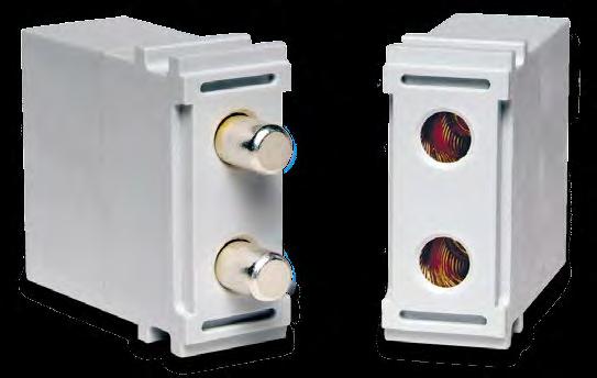
9 The Contact Principle Product Description Product Description ODU contacts fulfil the highest quality standards and ensure reliable connections. ODU uses different proven contact technologies. Turned contacts are fundamentally classified as either: Lamella contacts or Springwire contacts. These contacts differ only in the socket piece; the pins are the same and are always solid. ODU SPRINGTAC (contacts with springwire technology) The springwire contact is the inspired invention of Otto Dunkel. It offers the highest number of contact surfaces. The spring wires are mounted individually and joined optimally to a turned carrier. The individual springwires contact and cushion independently of one another. Unmated Socket Pin Advantages More than 100,000 mating cycles High current carrying capacity (up to 2,000 A) Carrier Expansion ring Springwire Spark protection Low contact resistances Large number of independently cushioning contact springs Mated Socket Pin Low insertion forces Extremely secure contacting High resistance to vibrations and impacts Long life span due to premium materials and surfaces Many styles and termination types are on hand or feasible. Page 9


10 Product Description ODU-MAC Product Description ODU LAMTAC (contacts with lamella technology) Unmated Socket Pin The lamella contact offers fewer contact surfaces than the ODU SPRINGTAC contact. One or more stamped lamellas are mounted in a turned carrier. Usually 10,000 mating cycles are possible. Advantages More than 10,000 mating cycles High current carrying capacity Low contact resistances Low insertion forces Carrier Lamella Secure contacting High resistance to vibrations and impacts Mated Socket Pin Long life due to premium materials and surfaces Many styles and termination types are on hand or feasible Economical alternative to springwire contacts. Page 10
.")

 This figure shows the attachment of a contact in the insulator.")
11 Insulators Product Description Product Description ODU currently manufactures 30 different versions of insulators. The figure here shows a few examples. The insulators are made of glass-filled thermoplastic materials (listed in accordance with UL-94). Special versions made of liquid crystal polymer (LCP) are available in several module types for special requirements (high temperature, radioactivity). The insulator width is 2.54 mm or a multiple of this. The contacts are snapped into place in the insulator. In most cases, they can be removed again in a few seconds with a tool. The insulators are held in the aluminium rails or DIN frame with powerful guide profiles. Contact Attachment with Clip Principle (Standard) This figure shows the attachment of a contact in the insulator. The contact is slid into the insulator from the termination side (from the back) and is latched when the metal clip (barbed hook) snaps behind a collar. The contacts can be removed again easily with a removal tool. This mounting method has the advantage of crimp termination technology, which permanently mounted, pressed contacts do not offer. This type of mounting allows the voltage levels to be raised reliably when contact positions are left free. Contact assembly is possible independently of the insulator. Further mounts are likewise available for different contact types, such as media feed-throughs. Contacts can be attached to the modules in different ways (here: attachment with clip). Clip Page 11
12 Product Description ODU-MAC For Your Notes Page 12
13 Page 13
 Operating voltage: 1) 250 V Rated impulse voltage: 1) 1,500 V Rated current: 2) 7.5 A at 0.38 mm² Pollution degree: 1) 2 Mating cycles: min.")
14 Overview of All for ODU-MAC Description Units/width Electrical properties Page 10 positions for turned contacts contact : 0.76 mm 1 unit (2.54 mm) Operating voltage: 1) 250 V Rated impulse voltage: 1) 1,500 V Rated current: 2) 7.5 A at 0.38 mm² Pollution degree: 1) 2 Mating cycles: min. 100, positions for stamped contacts 1 unit (2.54 mm) Operating voltage: 1) 32 V Rated impulse voltage: 1) 1,500 V Rated current: 2) 4.5 A at 0.38 mm² Pollution degree: 1) 2 Mating cycles: min. 5, positions for turned contacts contact : 1.02 mm 2 units (5.08 mm) Operating voltage: 1) 400 V Rated impulse voltage: 1) 3,000 V Rated current: 2) 9 A at 0.5 mm² Pollution degree: 1) 2 Mating cycles: min. 100, positions for turned contacts contact : 1.02 mm 3 units (7.62 mm) Operating voltage: 1) 320 V Rated impulse voltage: 1) 2,500 V Rated current: 2) 9 A at 0.5 mm² Pollution degree: 1) 2 Mating cycles: min. 100, positions for turned contacts contact : 1.5 mm 2 units (5.08 mm) Operating voltage: 1) 500 V Rated impulse voltage: 1) 2,500 V Rated current: 2) 18 A at 1.5 mm² Pollution degree: 1) 2 Mating cycles: min. 100, positions for turned contacts contact : 2.41 mm 3 units (7.62 mm) Operating voltage: 1) 500 V Rated impulse voltage: 1) 3,000 V Rated current: 2) 28 A at AWG 12 Pollution degree: 1) 2 Mating cycles: min. 100, According to DIN EN : 2007 (VDE 0110 part 1). 2 Determined to DIN : 2002 with 45 K increase of temperature. Page 14
 Operating voltage: 1) 500 V Rated impulse voltage: 1) 3,000 V Rated current: 2) 39 A at 6 mm² Pollution degree: 1) 2 Mating cycles: min. 100,000 32 2 positions for turned contacts contact : 5.")
 Operating voltage: 1) 2,500 V Rated impulse voltage: 1) 10,000 V Rated current: 2) 18 A at 1.")
 Operating voltage: 1) 2,500 V Rated impulse voltage: 1) 10,000 V Rated current: 2) 39 A at 6 mm² Pollution degree: 1) 2 Mating cycles: min.")
15 Description Units/width Electrical properties Page 3 positions for turned contacts contact : 3.0 mm 3 units (7.62 mm) Operating voltage: 1) 500 V Rated impulse voltage: 1) 3,000 V Rated current: 2) 39 A at 6 mm² Pollution degree: 1) 2 Mating cycles: min. 100, positions for turned contacts contact : 5.0 mm 5 units (12.7 mm) Operating voltage: 1) 1,000 V Rated impulse voltage: 1) 4,000 V Rated current: 2) 80 A at 16 mm² Pollution degree: 1) 2 Mating cycles: min. 100, positions high voltage module with turned contacts contact : 1.5 mm 3 units (7.62 mm) Operating voltage: 1) 2,500 V Rated impulse voltage: 1) 10,000 V Rated current: 2) 18 A at 1.5 mm² Pollution degree: 1) 2 Mating cycles: min. 100, positions power module with turned contacts contact : 3.0 mm 4 units (10.16 mm) Operating voltage: 1) 2,500 V Rated impulse voltage: 1) 10,000 V Rated current: 2) 39 A at 6 mm² Pollution degree: 1) 2 Mating cycles: min. 100, positions for power contacts ODU LAMTAC (contacts with lamella technology) with turned contacts contact : 8.0 mm 6 units (15.24 mm) Operating voltage: 1) 500 V Rated impulse voltage: 1) 3,000 V Rated current: 2) 105 A at 25 mm² Pollution degree: 1) 2 Mating cycles: min. 10, positions for power contacts ODU SPRINGTAC (contacts with springwire technology) with turned contacts contact : 8.0 mm 6 units (15.24 mm) Operating voltage: 1) 500 V Rated impulse voltage: 1) 3,000 V Rated current: 2) 100 A at 25 mm² Pollution degree: 1) 2 Mating cycles: min. 100, According to DIN EN : 2007 (VDE 0110 part 1). 2 Determined to DIN : 2002 with 45 K increase of temperature. Page 15
 at both versions Version: 10 mm 12 mm Operating voltage: 1) 250 V 200 V Rated impulse voltage: 1) 4,000 V 3,000 V Rated current: 2) 120 A 145 A at 35 mm² at 50 mm² Pollution degree: 1) 2 2")
16 Description Units/width Electrical properties Page 1 position for power contacts ODU LAMTAC (contacts with lamella technology) lamella 10 mm or lamella 12 mm 7 units (17.78 mm) at both versions Version: 10 mm 12 mm Operating voltage: 1) 250 V 200 V Rated impulse voltage: 1) 4,000 V 3,000 V Rated current: 2) 120 A 145 A at 35 mm² at 50 mm² Pollution degree: 1) 2 2 Mating cycles: min. 10,000 min. 10, position for high voltage contacts 8 units (20.32 mm) Operating voltage: 1) 6,300 V Rated impulse voltage: 1) 20,000 V Pollution degree: 1) 2 Mating cycles: min. 10, positions for 50 Ω coaxial contacts non-magnetic 3 units (7.62 mm) Frequency range: GHz Mating cycles: min. 60, positions for 50 Ω coaxial contacts 5 units (12.7 mm) Frequency range: GHz Mating cycles: min. 100, positions for 50 Ω coaxial contacts SMA termination 5 units (12.7 mm) Frequency range: GHz Mating cycles: min. 100, positions for 50 Ω coaxial contacts high voltage non-magnetic 5 units (12.7 mm) Frequency range: GHz Mating cycles: min. 100, According to DIN EN : 2007 (VDE 0110 part 1). 2 Determined to DIN : 2002 with 45 K increase of temperature. Page 16
 Frequency range: 0 2 GHz Mating cycles: min.")

 Tube diameter: max.")
 Insertion loss typical: 1.")
17 Description Units/width Electrical properties Page 2 positions for 75 Ω coaxial contacts 5 units (12.7 mm) Frequency range: 0 2 GHz Mating cycles: min. 100, Module 2 positions for compressed air valves 5 units (12.7 mm) Tube diameter: max. 4 mm Mating cycles: min. 5, Module 1 position for compressed air valve 8 units (20.32 mm) Tube diameter: max. 6 mm Mating cycles: min. 5, Module 2 positions for compressed air valves 16 units (40.64 mm) Tube diameter: max. 6 mm Mating cycles: min. 5, Module for fluid coupling plug 5 units (12.7 mm) Mating cycles: min. 15, positions for fibre-optic contacts for plastic fibre 5 units (12.7 mm) Insertion loss typical: 1.5 db at 670 nm Mating cycles: min. 100, According to DIN EN : 2007 (VDE 0110 part 1). 2 Determined to DIN : 2002 with 45 K increase of temperature. Page 17
 Insertion loss typical: 1.")
 Mating cycles: min. 5,000 With springwire: min.")
 Mating cycles: min. 5,000 78 1 According to DIN EN 60664.")
18 Description Units/width Electrical properties Page 5 positions for fibre-optic contacts for plastic fibre 2 units (5.08 mm) Insertion loss typical: 1.5 db at 670 nm Mating cycles: min. 40, positions for fibre-optic contacts for fibre-glass 4 units (10.16 mm) Insertion loss typical: 1.0 db at 670 nm Mating cycles: min. 100, to 10 positions, shielded implementation insert size 0 5 units (12.7 mm) Mating cycles: min. 5, to 14 positions, shielded implementation insert size 1 6 units (15.24 mm) Mating cycles: min. 5,000 With springwire: min. 60, to 8 positions, shielded implementation insert size 2 7 units (17.78 mm) Mating cycles: min. 5,000 With springwire: min. 60, to 30 positions, shielded implementation insert size 3 8 units (20.32 mm) Mating cycles: min. 5, According to DIN EN : 2007 (VDE 0110 part 1). 2 Determined to DIN : 2002 with 45 K increase of temperature. Page 18
 3 units (7.")
 Coding modules 1 unit (2.")
 82 1 According to DIN EN 60664.")

19 Description Units/width Electrical properties Page Empty modules 1 unit (2.54 mm) 3 units (7.62 mm) 80 5 units (12.7 mm) Coding modules 1 unit (2.54 mm) 81 Pin protection modules 1 unit (2.54 mm) 82 1 According to DIN EN : 2007 (VDE 0110 part 1). 2 Determined to DIN : 2002 with 45 K increase of temperature. You can find further information on the modules on the following pages. Page 19
20 Module 10 Positions for turned contacts Technical data Voltage information 1) Operating voltage 250 V 32 V Rated impulse voltage 1,500 V 1,500 V Pollution degree 2 3 Voltage information acc. to MIL 2) Operating voltage 500 V Test voltage 1,500 V Mechanical data Total mating force (average) 13.5 N/module Total demating force (average) 9.8 N/module Contact diameter 0.76 mm Operating temperature 40 C to +125 C acc. UL 1977, second edition, max. 75 C Mating cycles min. 100,000 Materials Insulator Contact body Contact spring Contact finish Thermoplast, polyester fibre-glass reinforced acc. UL-94 Cu alloy Cu Be 0.75 µm Au over 1.25 µm Ni Technical details The current load information is valid for single contacts or fully equipped modules, accordingly. For use in connector systems, the load should be reduced according to VDE Contacts and insulators up to 250 C upon request. Crimp information: see page Acc. DIN EN : 2007 (VDE 0110 Teil 1). See page See from page 121 Removal tool I (angled) Removal of already assembled contacts (including cable). Part number Removal tool II Removal of contacts that have not been assembled yet (without cable may have to be cut off). Part number Page 20
21 Module 10 positions for turned contacts Insulator pin and socket Spacer Mating side Soldered connection unit Sealing plug Part number Insulator Spacer Pin contact short 1) Pin contact long 1) Socket contact 1) Pin contact short 1) Pin contact long 1) Socket contact 1) Pin contact short 1) Pin contact long 1) Socket contact 1) Sealing plug Non-magnetic version on request. 2 Determined to DIN :2002 with 45 K increase of temperature. Conductor Termination Nominal current 2) Contact resistance average cross-section Single contact Fully equipped module mm² AWG / mm A A (mω) / / Print termination 0.76 mm Page 21
22 Module 10 Positions for stamped contacts Technical data Voltage information 1) Operating voltage 32 V 10 V Rated impulse voltage 1,500 V 1,500 V Pollution degree 2 3 Voltage information acc. to MIL 2) Operating voltage 450 V Test voltage 1,350 V Mechanical data Total mating force (average) 5.0 N/module Total demating force (average) 4.8 N/module Contact diameter 0.7 mm Operating temperature 40 C to +125 C Mating cycles min. 5,000 Materials Insulator Thermoplast, polyester fibre-glass reinforced acc. UL-94 Contact Cu Sn 6 Contact finish at termination area 3 µm Sn at contact area 0.75µm Au Technical details The current load information is valid for single contacts or fully equipped modules, accordingly. For use in connector systems, the load should be reduced according to VDE The 10 position modules with turned contacts are not compatible with those are stamped. Crimp information: see page 108 Contacts cannot be removed. 1 Acc. DIN EN : 2007 (VDE 0110 part 1). See page See from page 121 Page 22
23 Module 10 positions for stamped contacts Insulator pin and socket Spacer Sealing plug Mating side unit Print version Pin Socket Part number Insulator socket (crimp) Insulator pin (crimp) Insulator socket (with print) Spacer Pin contact *) Socket contact *) Pin contact *) Socket contact *) 1 Determined to DIN :2002 with 45 K increase of temperature. Conductor Termination Nominal current 1) Contact resistance cross-section Single contact Fully equipped module average mm² AWG A A (mω) 0.15 / / / / * Packaging for crimp version (per reel) Piece number ,000 10,000 20,000 Code number Page 23
 Operating voltage 850 V Test voltage 2,550 V Mechanical data Total mating force (average) 8.1 N/module Total demating force (average) 5.9 N/module Contact diameter 1.")
24 Module 6 Positions Technical data Voltage information 1) Operating voltage 400 V 160 V Rated impulse voltage 3,000 V 3,000 V Pollution degree 2 3 Voltage information acc. to MIL 2) Operating voltage 850 V Test voltage 2,550 V Mechanical data Total mating force (average) 8.1 N/module Total demating force (average) 5.9 N/module Contact diameter 1.02 mm Operating temperature 40 C to +125 C Mating cycles min. 100,000 Materials Insulator Contact body Contact spring Contact finish Thermoplast, polyester fibre-glass reinforced acc. UL-94 Cu alloy Cu Be 0.75 µm Au over 1.25 µm Ni Technical details The current load information is valid for single contacts or fully equipped modules, accordingly. For use in connector systems, the load should be reduced according to VDE Contacts and insulators up to 250 C on request. Crimp information: see page Acc. DIN EN : 2007 (VDE 0110 part 1). See page See from page 121 Removal tool I (angled) Removal of already assembled contacts (including cable). Part number Removal tool II Removal of contacts that have not been assembled yet (without cable may have to be cut off). Part number Page 24
25 Module 6 positions Insulator pin and socket Spacer Sealing plug Mating side units Print version Part number Insulator Spacer Pin contact short 1) Pin contact long 1) Socket contact 1) Pin contact short 1) Pin contact long 1) Socket contact 1) Pin contact short 1) Pin contact long 1) Socket contact 1) Sealing plug Non-magnetic version on request. 2 Determined to DIN :2002 with 45 K increase of temperature. Conductor Termination Nominal current 2) Contact resistance cross-section Single contact Fully equipped module average mm² AWG / mm A A mω 0.50 / / / / Print termination 0.76 mm Page 25
 Operating voltage 950 V Test voltage 2,850 V Mechanical data Total mating force (average) 18.9 N/module Total demating force (average) 13.7 N/module Contact diameter 1.")
26 Module 14 Positions Technical data Voltage information 1) Operating voltage 320 V 100 V Rated impulse voltage 2,500 V 2,500 V Pollution degree 2 3 Voltage information acc. to MIL 2) Operating voltage 950 V Test voltage 2,850 V Mechanical data Total mating force (average) 18.9 N/module Total demating force (average) 13.7 N/module Contact diameter 1.02 mm Operating temperature 40 C to +125 C Mating cycles min. 100,000 Materials Insulator Contact body Contact spring Contact finish Thermoplast, polyester fibre-glass reinforced acc. UL-94 Cu alloy Cu Be 0.75 µm Au over 1.25 µm Ni Technical details The current load information is valid for single contacts or fully equipped modules, accordingly. For use in connector systems, the load should be reduced according to VDE Contacts and insulators up to 250 C on request. Crimp information: see page Acc. DIN EN : 2007 (VDE 0110 part 1). See page See from page 121 Removal tool I (angled) Removal of already assembled contacts (including cable). Part number Removal tool II Removal of contacts that have not been assembled yet (without cable may have to be cut off). Part number Page 26
27 Module 14 positions Insulator pin and socket Spacer Sealing plug Mating side Print version units Part number Insulator Spacer Pin contact short 1) Pin contact long 1) Socket contact 1) Pin contact short 1) Pin contact long 1) Socket contact 1) Pin contact short 1) Pin contact long 1) Socket contact 1) Sealing plug Non-magnetic version on request. 2 Determined to DIN :2002 with 45 K increase of temperature. Conductor Termination Nominal current 2) Contact resistance cross-section Single contact Fully equipped module average mm² AWG / mm A A mω 0.50 / / / / Print termination 1.02 mm Page 27
28 Module 5 Positions Technical data Voltage information 1) Operating voltage 500 V 200 V Rated impulse voltage 2,500 V 2,500 V Pollution degree 2 3 Voltage information acc. to MIL 2) Operating voltage 750 V Test voltage 2,250 V Mechanical data Total mating force (average) 22.5 N/module Total demating force (average) 15.0 N/module Contact diameter 1.5 mm Operating temperature 40 C to +125 C Mating cycles min. 100,000 Materials Insulator Thermoplast, polyester fibre-glass reinforced acc. UL-94 Cu alloy Cu Sn Contact body Contact spring Contact finish Contact body 0.75 µm Au over 1.25 µm Ni Contact spring 3 µm Ag Technical details The current load information is valid for single contacts or fully equipped modules, accordingly. For use in connector systems, the load should be reduced according to VDE Contacts and insulators up to 250 C on request. Crimp information: see page Acc. DIN EN : 2007 (VDE 0110 part 1). See page See from page 121 Removal tool I (straight) Removal of already assembled contacts (including cable). Part number Removal tool I (angled) Removal of already assembled contacts (including cable). Part number Removal tool II Removal of contacts that have not been assembled yet (without cable may have to be cut off). Part number Page 28
29 Module 5 positions Insulator pin and socket Spacer Sealing plug Mating side 8 19 Print version units Part number Insulator Spacer Pin contact short 1) Pin contact long 1) Socket contact 1) Pin contact short Pin contact long Socket contact Pin contact short 1) Pin contact long 1) Socket contact 1) Pin contact short 1) Pin contact long 1) Socket contact 1) Pin contact short Pin contact long Socket contact Pin contact short Pin contact long Socket contact Sealing plug Non-magnetic version on request. 2 Determined to DIN :2002 with 45 K increase of temperature. Conductor Termination Nominal current 2) Contact resistance cross-section Single contact Fully equipped module average mm² AWG / mm A A mω / / / / Print termination 1.5 mm Page 29
 Operating voltage 1,100 V Test voltage 3,300 V Mechanical data Total mating force (average) 27.0 N/module Total demating force (average) 21.0 N/module Contact diameter 2.")
30 Module 4 Positions Technical data Voltage information 1) Operating voltage 500 V 200 V Rated impulse voltage 3,000 V 3,000 V Pollution degree 2 3 Voltage information acc. to MIL 2) Operating voltage 1,100 V Test voltage 3,300 V Mechanical data Total mating force (average) 27.0 N/module Total demating force (average) 21.0 N/module Contact diameter 2.41 mm Operating temperature 40 C to +125 C Mating cycles min. 100,000 Materials Insulator Contact body Contact spring Contact finish Thermoplast, polyester fibre-glass reinforced acc. UL-94 Cu alloy Cu Sn 3 µm Ag Technical details The current load information is valid for single contacts or fully equipped modules, accordingly. For use in connector systems, the load should be reduced according to VDE Crimp information: see page Acc. DIN EN : 2007 (VDE 0110 part 1). See page See from page 121 Removal tool I (straight) Removal of already assembled contacts (including cable). Part number Removal tool II Removal of contacts that have not been assembled yet (without cable may have to be cut off). Part number Page 30
31 Module 4 positions Insulator pin and socket Spacer Sealing plug Mating side units Print version Part number Insulator Spacer Pin contact short Pin contact long Socket contact Pin contact short 1) Pin contact long 1) Socket contact 1) Pin contact short Pin contact long Socket contact Pin contact short Pin contact long Socket contact Pin contact short Pin contact long Socket contact Pin contact short Pin contact long Socket contact Sealing plug Non-magnetic version on request. 2 Determined to DIN :2002 with 45 K increase of temperature. Conductor Termination Nominal current 2) Contact resistance cross-section Single contact Fully equipped module average mm² AWG / mm A A mω / / Print termination 2.4 mm Page 31
 Operating voltage 1,200 V Test voltage 3,600 V Mechanical data Total mating force (average) 36.0 N/module Total demating force (average) 24.75 N/module Contact diameter 3.")
32 Module 3 Positions Technical data Voltage information 1) Operating voltage 500 V 200 V Rated impulse voltage 3,000 V 3,000 V Pollution degree 2 3 Voltage information acc. to MIL 2) Operating voltage 1,200 V Test voltage 3,600 V Mechanical data Total mating force (average) 36.0 N/module Total demating force (average) N/module Contact diameter 3.0 mm Operating temperature 40 C to +125 C Mating cycles min. 100,000 Materials Insulator Contact body Contact spring Contact finish Thermoplast, polyester fibre-glass reinforced acc. UL-94 Cu alloy Cu Sn 3 µm Ag Technical details The current load information is valid for single contacts or fully equipped modules, accordingly. For use in connector systems, the load should be reduced according to VDE Crimp information: see page Acc. DIN EN : 2007 (VDE 0110 part 1). See page See from page 121 Removal tool I (straight) Removal of already assembled contacts (including cable). Part number Removal tool I (angled) Removal of already assembled contacts (including cable). Part number Removal tool II Removal of contacts that have not been assembled yet (without cable may have to be cut off). Part number Page 32
33 Module 3 positions Insulator pin and socket Mating side Spacer 12.1 Sealing plug units Part number Insulator Spacer Pin contact short Pin contact long Socket contact Pin contact short 1) Pin contact long 1) Socket contact 1) Pin contact short Pin contact long Socket contact Pin contact short 1) Pin contact long Socket contact 1) Pin contact short Pin contact long 1) Socket contact 1) Pin contact short Pin contact long Socket contact Sealing plug Non-magnetic version on request. 2 Determined to DIN :2002 with 45 K increase of temperature. Conductor Termination Nominal current 2) Contact resistance cross-section Single contact Fully equipped module average mm² AWG A A mω / / Page 33
34 Module 2 Positions Technical data Voltage information 1) Operating voltage 1,000 V 250 V Rated impulse voltage 4,000 V 4,000 V Pollution degree 2 3 Voltage information acc. to MIL 2) Operating voltage 1,250 V Test voltage 3,750 V Mechanical data Total mating force (average) 51.0 N/module Total demating force (average) 36.0 N/module Contact diameter 5.0 mm Operating temperature 40 C to +125 C Mating cycles min. 100,000 Materials Insulator Contact body Contact spring Contact finish Thermoplast, polyester fibre-glass reinforced acc. UL-94 Cu alloy Cu Sn 3 µm Ag Technical details The current load information is valid for single contacts or fully equipped modules, accordingly. For use in connector systems, the load should be reduced according to VDE Crimp information: see page 108. Removal tool Removal of already assembled contacts (including cable). Part number Acc. DIN EN : 2007 (VDE 0110 part 1). See page See from page 121 Page 34
35 Module 2 positions Insulator pin and socket Mating side Spacer Sealing plug units Part number Insulator Spacer Pin contact short Pin contact long Socket contact Pin contact short Pin contact long Socket contact Pin contact short Pin contact long Socket contact Sealing plug Determined to DIN :2002 with 45 K increase of temperature. Conductor cross-section Nominal current 1) Single contact Fully equipped module Contact resistance average mm² A A mω Page 35
 Operating voltage 2,500 V Test voltage 7,500 V Mechanical data Total mating force (average) 18.0 N/module Total demating force (average) 12.0 N/module Contact diameter 1.")
36 Module 4 Positions, High Voltage Module Technical data Voltage information 1) Operating voltage 2,500 V 1,000 V Rated impulse voltage 10,000 V 8,000 V Pollution degree 2 3 Voltage information acc. to MIL 2) Operating voltage 2,500 V Test voltage 7,500 V Mechanical data Total mating force (average) 18.0 N/module Total demating force (average) 12.0 N/module Contact diameter 1.5 mm Operating temperature 40 C to +125 C Mating cycles min. 100,000 Materials Insulator Thermoplast, polyester fibre-glass reinforced acc. UL-94 Cu alloy Cu Sn Contact body Contact spring Contact finish Contact body 0.75 µm Au over 1.25 µm Ni Contact spring 3 µm Ag Technical details The current load information is valid for single contacts or fully equipped modules, accordingly. For use in connector systems, the load should be reduced according to VDE Crimp information: see page Acc. DIN EN : 2007 (VDE 0110 part 1). See page See from page 121 Removal tool I (straight) Removal of already assembled contacts (including cable). Part number Removal tool II Removal of contacts that have not been assembled yet (without cable may have to be cut off). Part number Page 36
37 Module 4 Positions, High Voltage Module Insulator socket Insulator pin Sealing plug Mating side 30.2 Mating side units Insulator socket Insulator pin Spacer Pin contact short 1) Pin contact long 1) Socket contact 1) Pin contact short Pin contact long Socket contact Pin contact short 1) Pin contact long 1) Socket contact 1) Pin contact short 1) Pin contact long 1) Socket contact 1) Pin contact short Pin contact long Socket contact Pin contact short Pin contact long Socket contact Sealing plug Part number Conductor cross-section Nominal current 2) Contact resistance Single contact Fully equipped module average mm² AWG / mm A A mω 1 Non-magnetic version on request. 2 Determined to DIN :2002 with 45 K increase of temperature / / / / Print termination 1.5 mm Page 37
 Operating voltage 2,500 V Test voltage 7,500 V Mechanical data Total mating force (average) 23.1 N/module Total demating force (average) 19.6 N/module Contact diameter 3.")
38 Module 3 Positions, Power Module Technical data Voltage information 1) Operating voltage 2,500 V 1,000 V Rated impulse voltage 10,000 V 8,000 V Pollution degree 2 3 Voltage information acc. to MIL 2) Operating voltage 2,500 V Test voltage 7,500 V Mechanical data Total mating force (average) 23.1 N/module Total demating force (average) 19.6 N/module Contact diameter 3.0 mm Operating temperature 40 C to +125 C acc. UL 1977, second edition, max. 75 C Mating cycles min. 100,000 Materials Insulator Contact body Contact spring Contact finish Thermoplast, Polyester fibre-glass reinforced acc. UL-94 Cu alloy Cu Sn 3 µm Ag Technical details The current load information is valid for single contacts or fully equipped modules, accordingly. For use in connector systems, the load should be reduced according to VDE Crimp information: see page Acc. DIN EN : 2007 (VDE 0110 part 1). See page See from page 121 Removal tool I (straight) Removal of already assembled contacts (including cable). Part number Removal tool II Removal of contacts that have not been assembled yet (without cable may have to be cut off). Part number Page 38
39 Module 3 positions, power module Insulator socket Insulator pin Sealing plug Mating side 28.1 Mating side units Insulator socket Insulator pin Pin contact Pin contact long Socket contact Pin contact 1) Pin contact long 1) Socket contact 1) Pin contact Pin contact long Socket contact Pin contact 1) Pin contact long Socket contact 1) Pin contact Pin contact long 1) Socket contact 1) Pin contact Pin contact long Socket contact Sealing plug Part number Conductor cross-section Nominal current 2) Contact resistance Single contact Fully equipped module average mm² AWG A A mω 1 Non-magnetic version on request. 2 Determined to DIN :2002 with 45 K increase of temperature / / Page 39
 Operating voltage 900 V Test voltage 2,700 V Mechanical data Total mating force (average) 60.0N/module Total demating force (average) 45.")
40 Module 2 Positions for Power Contacts ODU LAMTAC (Contacts with Lamella Technology) Technical data Voltage information 1) Operating voltage 500 V 200 V Rated impulse voltage 3,000 V 3,000 V Pollution degree 2 3 Voltage information acc. to MIL 2) Operating voltage 900 V Test voltage 2,700 V Mechanical data Total mating force (average) 60.0N/module Total demating force (average) 45.0 N/module Contact diameter 8.0 mm Operating temperature 40 C to +125 C Mating cycles min. 10,000 Materials Insulator Contact body Contact lamella Contact finish Thermoplast, polyester fibre-glass reinforced acc. UL-94 Cu alloy Cu Be 3 µm Ag Technical details The current load information is valid for single contacts or fully equipped modules, accordingly. For use in connector systems, the load should be reduced according to VDE Crimp information: see page 108. Assembly tool To screw down the contacts. Part number Tightening torque: 3.5 Nm ± 0.5 Nm 1 Acc. DIN EN : 2007 (VDE 0110 part 1). See page See from page 121 Page 40
41 Module 2 positions for power contacts ODU LAMTAC (contacts with lamella technology) Insulator pin and socket Mating side ODU LAMTAC (contacts with lamella technology) The ODU LAMTAC contact offers fewer contact surfaces than does the ODU SPRINGTAC contact. One or more stamped lamellas are mounted into a turned carrier. At least 10,000 mating cycles are possible. 45 Unmated Socket Pin Carrier Lamella units Mated Socket Pin Insulator Pin contact Socket contact Pin contact Socket contact Part number Conductor cross-section 2) Nominal current 1) Contact resistance Single contact Fully equipped module average mm² A A mω 1 Determined to DIN :2002 with 45 K increase of temperature. 2 Extra fine wires according to VDE 0295, class Page 41
42 Module 2 Positions for Power Contacts ODU SPRINGTAC (Contacts with Springwire Technology) Technical data Voltage information 1) Operating voltage 500 V 200 V Rated impulse voltage 3,000 V 3,000 V Pollution degree 2 3 Voltage information acc. to MIL 2) Operating voltage 700 V Test voltage 2,100 V Mechanical data Total mating force (average) approx. 60 N/module Total demating force (average) approx N/module Contact diameter 8.0 mm Operating temperature 40 C to +125 C Mating cycles min. 100,000 Materials Insulator Contact Contact spring Contact finish Thermoplast, polyester fibre-glass reinforced acc. UL-94 Cu alloy Cu Sn 3 µm Ag Technical details The current load information is valid for single contacts or fully equipped modules, accordingly. For use in connector systems, the load should be reduced according to VDE Acc. DIN EN : 2007 (VDE 0110 part 1). See page See from page 121 Assembly tool To screw down the contacts. Part number Tightening torque: 3.5 Nm ± 0.5 Nm Page 42
43 Module 2 positions for power contacts ODU SPRINGTAC (contacts with springwire technology) Insulator socket and pin Mating side units Part number Conductor 2) Nominal current 1) Contact resistance cross-section Single contact Fully equipped module average mm² A A mω Insulator Pin contact Socket contact Pin contact Socket contact Determined to DIN :2002 with 45 K increase of temperature. 2 Extra fine wires according to VDE 0295, class Page 43

44 Module 1 Position for Power Contacts ODU LAMTAC (Contacts with Lamella Technology) Technical data Voltage information 1) Contact diameter 10 mm or 12 mm Operating voltage 10 mm 250 V 160 V 12 mm 200 V 63 V Rated impulse voltage 10 mm 4,000 V 4,000 V 12 mm 3,000 V 3,000 V Pollution degree 10 mm mm 2 3 Voltage information acc. to MIL 2) Operating voltage 10 mm 2,000 V 12 mm 1,500 V Test voltage 10 mm 6,000 V 12 mm 4,500 V Mechanical data Total mating force (average) 10 mm 33.0 N/module 12 mm 45.0 N/module Total demating force (average) 10 mm 24.0 N/module 12 mm 30.0 N/module Operating temperature 40 C to +125 C Mating cycles min. 10,000 Materials Insulator Contact body Contact lamella Contact finish Thermoplast, polyester fibre-glass reinforced acc. UL-94 Cu alloy Cu Be 3 µm gal. Ag Assembly tool To screw down the contacts. Part number 10 mm: Part number 12 mm: Tightening torque: 3.5 Nm ± 0.5 Nm Technical details The current load information is valid for single contacts or fully equipped modules, accordingly. For use in connector systems, the load should be reduced according to VDE Crimp information: see page Acc. DIN EN : 2007 (VDE 0110 part 1). See page See from page 121 Page 44


 Nominal current 1) Contact resistance average mm² A mω 35.00 120 0.15 25.00 110 0.15 50.00 145 0.10 35.")
45 Module 1 position for power contacts ODU LAMTAC (contacts with lamella technology) Insulator pin and socket ODU LAMTAC (contacts with lamella technology) Mating side The ODU LAMTAC contact offers fewer contact surfaces than does the ODU SPRINGTAC contact. One or more stamped lamellas are mounted into a turned carrier. Usually 10,000 mating cycles are possible. 50 Unmated Socket Pin Carrier Lamella Mated Socket Pin units 30 Insulator for contact 10 mm Insulator for contact 12 mm Pin contact 10 mm Socket contact 10 mm Pin contact 10 mm Socket contact 10 mm Pin contact 12 mm Socket contact 12 mm Pin contact 12 mm Socket contact 12 mm Pin contact 12 mm Socket contact 12 mm Determined to DIN :2002 with 45 K increase of temperature. 2 Extra fine wires according to VDE 0295, class 5 Part number Conductor cross-section 2) Nominal current 1) Contact resistance average mm² A mω Page 45
 according to VDE PDV inception voltage 6,000 V PDV extinction voltage 5,700 V Mechanical data Total mating force (average) 17.")

46 Module 1 Position for High Voltage Contacts Technical data Voltage information 1) Operating voltage 6,300 V 2,500 V Rated impulse voltage 20,000 V 20,000 V Pollution degree 2 3 Clearance distance >32 mm Creepage distance >32 mm Test of the partial discharge voltage (PDV) according to VDE PDV inception voltage 6,000 V PDV extinction voltage 5,700 V Mechanical data Total mating force (average) 17.0 N/module Total demating force (average) 15.0 N/module Contact diameter 2.0 mm Operating temperature 40 C to +125 C Mating cycles min. 10,000 Materials Insulator Thermoplast, polyester fibre-glass reinforced acc. UL-94 Cu alloy/ptfe Cu Be Contact Contact spring Contact finish Outer contact 1.25 µm gal. Ni Center contact 3.00 µm gal. Ag Technical details The current load information is valid for single contacts or fully equipped modules, accordingly. For use in connector systems, the load should be reduced according to VDE Acc. DIN EN : 2007 (VDE 0110 part 1). See page 118 Page 46
47 Module 1 position for high voltage contacts Insulator pin and socket Socket contact Mating side Pin contact units Cable termination Stripping length Insulation Cable Single conductor Shielding Part number Part number crimp die Conductor cross-section Maximum nominal current Contact resistance average AWG / mm² A mω Insulator Pin contact Socket contact / Crimping tool for shielding High voltage cable mm² Page 47
48 Module 4 Positions for 50 Ω Coaxial Contacts Non-Magnetic Technical data Voltage information Frequency range 2) GHz Insulation resistance > 100 GΩ Voltage information acc. to MIL 1) Operating voltage 350 V Test voltage 1,050 V Mechanical data Total mating force (average) 17.8 N/module Total demating force (average) 15.3 N/module Operating temperature 40 C to +125 C Mating cycles min. 60,000 Materials Insulator Contacts Thermoplast, polyester fibre-glass reinforced acc. UL-94 Cu alloy /PTFE 0.8 µm Au over 2.0 µm CuSnZn Technical details Crimp information see page See from page Loss levels depend on the conductor cross-section. These are available on request. High frequency characteristics for 50 Ω coaxial contacts 2) Insertion loss Loss in db Frequency in GHz Removal tool I (angled) Removal of already assembled contacts (including cable). Part number VSWR (voltage standing wave ratio) Removal tool II Removal of contacts that have not been assembled yet (without cable may have to be cut off). Part number Loss in db Frequency in GHz Page 48
49 Module 4 positions for 50 Ω coaxial contacts, non-magnetic Insulator pin and socket Spacer Stripping length Mating side Pin Socket units Part number Characteristic impedance Ω Cable 1) Part number crimp dies Insulator Spacer Pin contact straight RG 178 / RG Pin contact straight RG 174 / RG 188 / RG 316 (75 Ω: RG 179, RG 187) Pin contact straight G02232 (H+S) Socket contact straight RG 178, RG Socket contact straight RG 174 / RG 188 / RG 316 (75 Ω: RG 179, RG 187) Socket contact straight G (H+S) Crimping tool for shielding sleeve Special lines on request Page 49
 Operating voltage 400 V Test voltage 1,200 V Mechanical data Total mating force (average) 12.0 N/module Total demating force (average) 10.")
50 Module 2 Positions for 50 Ω Coaxial Contacts Technical data Voltage information Frequency range 2) 0 to 2.5 GHz Insulation resistance > 100 GΩ Voltage information acc. to MIL 1) Operating voltage 400 V Test voltage 1,200 V Mechanical data Total mating force (average) 12.0 N/module Total demating force (average) 10.8 N/module Operating temperature 40 C to +125 C Mating cycles min. 100,000 Materials Insulator Thermoplast, polyester fibre-glass reinforced acc. UL-94 Cu alloy Cu Sn Contact body Contact spring Contact finish Pin center contact 0.75 µm Au over 1.25 µm Ni Pin outer contact 6 µm Ni Socket center contact Springs 0.75 µm Au over 1.25 µm Ni Socket outer contact Springs 0.75 µm Au over 1.25 µm Ni High frequency characteristics for 50 Ω coaxial contacts 2) Insertion loss Technical details Crimp information see page See from page Loss levels depend on conductor cross-section. These are available on request. Loss in db Frequency in GHz VSWR (voltage standing wave ratio) Removal tool I Part number Loss in db Frequency in GHz Page 50
51 Module 2 positions for 50 Ω coaxial contacts Insulator pin and socket Cable termination Stripping length Mating side units Pin Socket Part number Characteristic impedance Ω Cable 1) Part number crimp dies Insulator Spacer Sealing plug Pin contact straight RG 178 / RG Pin contact straight RG 174 / RG 188 / RG Pin contact straight RG 122 (2YCY 0.4/ Ω) Pin contact straight RG Pin contact straight RG Pin contact straight G D (H+S) Socket contact straight RG 178 / RG Socket contact straight RG 174 / RG188 / RG Socket contact straight RG122 (2YCY 0.4/ Ω) Socket contact straight RG Socket contact straight RG Socket contact straight G D (H+S) Crimping tool for shielding sleeve Special lines on request Page 51
 Operating voltage 350 V Test voltage 1,050 V Mechanical data Total mating force (average) 9.0 N/module Total demating force (average) 7.")
52 Module 2 Positions for 50 Ω Coaxial Contacts SMA Termination Technical data Voltage information Frequency range 2) GHz Insulation resistance > 100 GΩ Voltage information acc. to MIL 1) Operating voltage 350 V Test voltage 1,050 V Mechanical data Total mating force (average) 9.0 N/module Total demating force (average) 7.5 N/module Operating temperature 40 C to +125 C Mating cycles min. 100,000 Materials Insulator Thermoplast, polyester fibre-glass reinforced acc. UL-94 Cu alloy Cu Sn Contact body Contact spring Contact finish Pin center contact 0.75 µm Au over 1.25 µm Ni Pin outer contact 6 µm Ni Socket center contact Springs 0.75 µm Au over 1.25 µm Ni Socket outer contact Springs 0.75 µm Au over 1.25 µm Ni High frequency characteristics for 50 Ω coaxial contacts, SMA termination 2) Insertion loss Technical details Crimp information see page See from page Loss levels depend on conductor cross-section. These are available on request. Loss in db Frequency in GHz VSWR (voltage standing wave ratio) Removal tool Part number Loss in db Frequency in GHz Page 52
53 Module 2 positions for 50 Ω coaxial contacts, SMA Termination Mating side 9.5 1/4-36 UNS-2A SW 7 SW 7 1/4-36 UNS-2A units Pin Socket Part number Characteristic impedance Ω Termination Insulator Spacer Sealing plug Pin contact straight SMA Socket contact straight SMA Page 53
 Operating voltage 850 V Test voltage 2,600 V Mechanical data Total mating force (average) 12.0 N/module Total demating force (average) 10.")
54 Module 2 Positions for 50 Ω Coaxial Contacts High Voltage, Non-Magnetic Technical data Voltage information Frequency range 2) 0 to 0.25 GHz Insulation resistance > 100 GΩ Voltage information acc. to MIL 1) Operating voltage 850 V Test voltage 2,600 V Mechanical data Total mating force (average) 12.0 N/module Total demating force (average) 10.8 N/module Operating temperature 40 C to +125 C Mating cycles min. 100,000 Materials Insulator Contact Surface Thermoplast, polyester fibre-glass reinforced acc. UL-94 Cu alloy 2 µm white bronze and 0.8 µm Au Technical details Crimp information see page See from page Loss levels depend on conductor cross-section. These are available on request. High frequency characteristics for 50 Ω coaxial contacts, high voltage, non-magnetic 2) Insertion loss Loss in db Frequency in GHz VSWR (voltage standing wave ratio) Removal tool Part number Loss in db Frequency in GHz Page 54
55 Module 2 positions for 50 Ω coaxial contacts, high voltage, non-magnetic Insulator pin and socket Cable termination Stripping length Mating side units Pin Socket Part number Characteristic impedance Ω Cable 1) Part number crimp dies Insulator Spacer Sealing plug Pin contact straight RG 178 / RG Pin contact straight RG 174 / RG 188 / RG Pin contact straight RG Pin contact straight RG Socket contact straight RG 178 / RG Socket contact straight RG 174 / RG 188 / RG Socket contact straight RG Socket contact straight RG Crimping tool for shielding sleeve Special lines on request Page 55
 Operating voltage 475 V Test voltage 1,425 V Mechanical data Total mating force (average) 9.0 N/module Total demating force (average) 7.")
56 Module 2 Positions for 75 Ω Coaxial Contacts Technical data Voltage information Frequency range 2) 0 to 2.0 GHz Insulation resistance > 100 GΩ Voltage information acc. to MIL 1) Operating voltage 475 V Test voltage 1,425 V Mechanical data Total mating force (average) 9.0 N/module Total demating force (average) 7.5 N/module Operating temperature 40 C to +125 C Mating cycles min. 100,000 Materials: Insulator Thermoplast, polyester fibre-glass reinforced acc. UL-94 Cu alloy Cu Sn Contact body Contact spring Contact finish Pin center contact 0.75 µm Au over 1.25 µm Ni Pin outer contact 4 µm Ni Socket center contact Springs 0.75 µm Au over 1.25 µm Ni Socket outer contact Springs 0.75 µm Au over 1.25 µm Ni High frequency characteristics for 75 Ω coaxial contacts 2) Insertion loss See from page Loss levels depend on conductor cross-section. These are available on request. Loss in db Frequency in GHz VSWR (voltage standing wave ratio) Removal tool Part number Loss in db Frequency in GHz Page 56
57 Module 2 positions for 75 Ω coaxial contacts Insulator pin and socket Cable termination Stripping length Mating side , units Pin 6.35 Socket Part number Characteristic impedance Ω Cable 1) Part number crimp dies Insulator Spacer Sealing plug Pin contact straight RG 179 / RG Pin contact straight G (H+S) Pin contact straight RG Socket contact straight RG 179 / RG Socket contact straight G (H+S) Socket contact straight RG Crimping tool for shielding sleeve Special lines on request Page 57
 not shut off 27 N/module one side shut off 28 N/module both side shut off 29 N/module Total demating force (average) not shut off 12.")
58 Module 2 Positions for Compressed Air Valves, Tube Diameter: max. 4 mm Technical data Mechanical data Valid operating pressure max. 20 bar Total mating force (average) not shut off 27 N/module one side shut off 28 N/module both side shut off 29 N/module Total demating force (average) not shut off 12.6 N/module one side shut off 12.6 N/module both side shut off 9.2 N/module Operating temperature 40 C to +125 C Mating cycles min. 5,000 (with regular maintenance intervals higher mating cycles are possible) Materials Insulator Valve body Composition Thermoplast, polyester fibre-glass reinforced acc. UL-94 Cu alloy, blank NBR Technical details Due to the function, the contacts are pre-stressed in the mated state. The frame must maintain this pre-stress with a holding device. Flow rate diagram Drop of pressure in bar Flow rate in l/min Page 58
59 Module 2 positions for compressed air valves, tube diameter: max. 4 mm Insulator pin and socket Mating side 13 Plug sleeve (pin) Coupling plug (socket) Termination Termination I Termination II A A units X Part number Dimension A Dimension X Termination I II mm mm Insulator Plug sleeve (not shut off) x Plug sleeve (not shut off) x Plug sleeve (not shut off) M5 x Coupling (not shut off) x Coupling (not shut off) x Coupling (not shut off) M5 x Plug sleeve (shut off) 1) 2) M5 x Coupling (shut off) x Coupling (shut off) x Coupling (shut off) 2) M5 x 1 Can only be plugged into coupling plug Sealing material: FKM Page 59
 1) not shut off 3.4 N/valve not shut off 3.4 N/valve Operating temperature 40 C to +125 C Mating cycles min.")

60 Module 1/2 Positions for Compressed Air Valves Tube Diameter: max. 6 mm Technical data Mechanical data Valid operating pressure max. 1/2 positions 12 bar Total mating force (average) not shut off 5.4 N/valve not shut off 6.4 N/valve Total demating force (average) 1) not shut off 3.4 N/valve not shut off 3.4 N/valve Operating temperature 40 C to +125 C Mating cycles min. 5,000 Materials Insulator Compressed air valves Sealing Thermoplast, polyester fibre-glass reinforced acc. UL-94 Cu alloy, blank NBR Technical details Two-sided shut-off version on request. Due to the function, the contacts are pre-stressed in the mated state. The frame must maintain this pre-stress with a holding device. Flow rate diagram Flow rate in l/min Drop of pressure in bar Page 60
61 Module 1/2 positions for compressed air valves, tube diameter: max. 6 mm Insulator socket (2 positions) Insulator pin Insulator pin and socket (1 position) Mating side 13 Mating side A units units Coupling plug socket Plug sleeve pin X X Part number Dimension A Dimension X mm mm Insulator socket 2 positions Insulator pin 2 positions Insulator Plug sleeve (not shut off) Plug sleeve (not shut off) Coupling plug (not shut off) Coupling plug (not shut off) Coupling plug (shut off) Coupling plug (shut off) Page 61
62 Module for Fluid Coupling Plug, Both Sides Shut Off, Low-Leakage Design Suitable for conducting air, water and other fluids Technical data Mechanical data Valid operating pressure max. 6 bar Tube termination Tube termination M5 internal screw thread, commercially available threaded joints Total mating force (average) 48 N/module Total demating force (average) 4.6 N/module Operating temperature 40 C to +125 C Mating cycles min. 15,000 Materials Insulator Compressed air valves Sealing Thermoplast, Polyester fibre-glass reinforced acc. UL-94 Brass, nickel-plated or stainless steel, FKM FKM Technical details Due to the function, the contacts are pre-stressed in the mated state. The frame must maintain this pre-stress with a holding device. The use of combustible or explosive liquids or gases is not permitted. Flow rate diagram air Flow rate Q in m³/h Drop of pressure P in bar Flow rate Q in l/min Flow rate diagram water Flow rate Q in m³/h Drop of pressure P in bar Flow rate Q in l/min Page 62
63 Module for fluid coupling plug, both sides shut off, low-leakage design Suitable for conducting air, water and other fluids Insulator pin and socket Mating side Pin Socket SW 6.5 Retaining ring SW 6.5 Retaining ring units M5 5,3 8, M Part number Version Insulator Sealing nipple (pin piece) stainless steel (standard) Sealing coupling plug (socket piece) stainless steel (standard) Sealing nipple (pin piece) nickel-plated brass Sealing coupling plug (socket piece) nickel-plated brass Page 63
64 Accessories for fluid coupling plug module Technical data Mechanical data Valid operating pressure (static) 0.95 to 14 bar Operating temperature 10 C to +80 C Threaded connection M 5 Plug-in nipple Threaded union Technical details Tightening torque: 1.5 Nm L-connector Dimension A Dimension B Part number mm mm Plug-in nipple Threaded union L-connector Page 64
65 Accessories for fluid coupling plug module Termination dimensions for fluid coupling plug accessory M 5 A A M 5 M 5 B B Assembly of the air coupling plug 1. Insert air coupling plug into the insulator. 2. Screw threaded joint into the air coupling plug. Tightening torque: 1.5 Nm. Page 65
 16.0 N Operating temperature Standard fibre 40 C to +85 C High temperature fibre 40 C to +115 C Mating cycles min.")
66 Module 2 Positions for Fibre-Optic Contacts for Plastic Fibre Technical data Mechanical data POF (Polymer Optical Fibre) 1 mm Outer diameter 2.2 mm resp. 2.3 mm Fibre fastening Clamping Insertion loss Typical 1.5 db at 670 nm During life-time < 2.0 db at 670 nm Total mating force (average) 16.0 N Operating temperature Standard fibre 40 C to +85 C High temperature fibre 40 C to +115 C Mating cycles min. 100,000 Materials Insulator Fibre-optic contact Type of fibre Thermoplast, polyester fibre-glass reinforced acc. UL-94 Cu alloy Plastic fibre 980/1000 (POF) or 980/1550 Technical details Due to the function, the contacts are pre-stressed in the mated state. The frame must maintain this pre-stress with a holding device. Please request the assembly instructions. Page 66
67 Module 2 positions for fibre-optic contacts for plastic fibre Insulator pin and socket Mating side 13 Pin Socket units A A (26.2) (28.9) Part number Dim. A mm Insulator Socket contact 980/1000 µm Pin contact 980/1000 µm Socket contact 980/1550 µm (MOST standard) Pin contact 980/1550 µm (MOST standard) Tool for cable-stripping Wrench/spanner 4.5 mm Wrench/box spanner 8 mm Polish-device for socket Spare blades Polish-device for pin Lapp foils, 12 µm, 5 µm Page 67
68 Module 5 Positions for Fibre-Optic Contacts for Plastic Fibre 1) Technical data Mechanical data POF (Polymer Optical Fibre) 1 mm Outer diameter 2.2 mm resp. 2.3 mm Fibre fastening Crimp Insertion loss Typical 1.5 db at 670 nm During life-time < 2.0 db at 670 nm Total mating force (average) < 17.5 N Operating temperature Standard fibre 40 C to +85 C High temperature fibre 40 C to +115 C Mating cycles min. 40,000 Materials Insulator Fibre-optic contact Type of fibre Thermoplast, polyester fibre-glass reinforced acc. UL-94 Cu alloy Plastic fibre 980/1000 (POF) Technical details Due to the function, the contacts are pre-stressed in the mated state. The frame must maintain this pre-stress with a holding device. Please request the assembly instructions. 1 Fibre-optic contacts for fibre-glass on request! Removal tool Removal from the front is possible, no cutting off required. Part number Page 68
69 Module 5 positions for fibre-optic contacts for plastic fibre Insulator pin and socket Pin units Socket 29.8 Part number Insulator Socket contact 980/ 1000 µm Pin contact 980/1,000 µm Set (strip- and crimpwrench) Tool for cable stripping Crimp tool Page 69
70 Module 3 Positions for Fibre-Optic Contacts for Fibre-Glass Technical data Mechanical data Fibre-glass Single mode 9/125 µm Multi mode 50/125 µm Multi mode 62.5/125 µm Fibre fastening Optical fibre glued 1) Surface polished 1) Sheath crimped Insertion loss typical <1.0 db Total mating force (average) 36.0 N Assembly holding force 10.0 to 12.0 N/contact Operating temperature 40 C to +85 C Mating cycles min. 100,000 Materials Insulator Ferrule holder Ferrule Spring Thermoplast, polyester fibre-glass reinforced acc. UL-94 Nickel silver Ceramic Cr Ni steel Technical details Due to the function, the contacts are pre-stressed in the mated state. The frame must maintain this pre-stress with a holding device. Please request the assembly instructions. 1 Fibre assembly (gluing and polishing) on request! Removal tool I (straight) Removal of the already assembled contact (including cable). Part number Removal tool II Removal of contact that has not been assembled yet (without cable may have to be cut off). Part number Page 70
71 Module 3 positions for fibre-optic contacts for fibre-glass Insulator socket Insulator pin Mating side Mating side units Socket 13 Pin units Part number Part number LWL fibre crimp die Insulator pin piece Insulator socket piece Pin contact / 125 µm; 62.5 / 125 µm Pin contact / 125 µm Socket contact / 125 µm, 62.5 / 125 µm Socket contact / 125 µm Crimping tool for shielding Page 71
72 Multi-Position Module (2 to 10 Positions), Shielded Implementation, Size 0 (e.g., for Use in Bus Systems) Technical data The inserts listed here for shielded implementations are optimally suitable for all common bus systems with transfer rates up to 10 MHz. For example, Profibus, USB1.1, RS485, Flexray, CAN-Bus and RS233. Selected inserts are suitable and qualified for data rates up to 480 MBit/s. For example, Fast-Ethernet, USB2.0, IEEE Mating cycles: min. 5,000. Assembly instruction (pin piece) Picture number Basis parts Part 1 number 2 1 Insulator Socket housing cpl Pin housing cpl Sealing plug Insert cpl. see next page 4 Assembly set see table Assembly set 3 Cable Part number 4 mm Page 72
73 Multi-position module (2 to 10 positions), shielded implementation, size 0 (e.g., for use in bus systems) Insulator pin and socket Pin Stripping length Mating side approx Single wire Cable 11.8 Socket approx Insulation 7 Shielding units 30 9 Contact arrangements Pin 2 positions 3 positions 4 positions 5 positions 6 positions 7 positions 9 positions 10 positions Socket Number of pos. Contact diameter Termination cross-section Rated voltage 1) Rated impulse voltage 1) Pollution degree 1) acc. VDE 110 mm AWG V kv V AC N N Pin Socket Pin Socket Pin CAT Socket CAT Pin USB Socket USB Pin Socket Pin Socket Pin Socket Pin Socket Pin Socket Acc. to DIN EN : 2007 (VDE 0110 Teil 1), see page Acc. to MIL SAE AS13441/IEC Nominal voltage 2) Version 3 Classification to IEC : Insert in crimp model on request. Category 3) Insert cpl. 4) part number Mating force Demating force Page 73
 Technical data The inserts listed here for shielded implementations are 2 1 4 optimally suitable for all common bus systems with transfer rates up to 10 MHz.")
74 Multi-Position Module (2 to 14 Positions), Shielded Implementation Size 1 (e.g., for Use in Bus Systems) Technical data The inserts listed here for shielded implementations are optimally suitable for all common bus systems with transfer rates up to 10 MHz. For example, Profibus, RS485, Flexray, CAN-Bus and RS Selected inserts are suitable and qualified for data rates up to 1 GBit/s. For example, Gigabit-Ethernet, Fast- Ethernet, IEEE 1394, Firewire S400, Firewire S800. Mating cycles: min. 5, Assembly instruction (pin piece) Picture number Basis parts Part number 1 Insulator Socket housing cpl Pin housing cpl Sealing plug Insert cpl. see next page 4 Cable collets see table 2 Cable collets Cable Part number mm Page 74
75 Multi-position module (2 to 14 positions), shielded implementation, size 1 (e.g., for use in bus systems) Insulator pin and socket Mating side 13 Pin 13 approx. 19 Stripping length Single wire Cable Insulation 9 Shielding 12.8 Socket approx units Contact arrangements Pin 2 positions 3 positions 4 positions 5 positions 6 positions 7 positions 8 positions 10 positions 14 positions Socket Number of pos. Contact diameter Termination cross-section Rated voltage 1) Rated impulse voltage 1) Pollution degree 1) acc. VDE 110 mm AWG V kv V AC N N Pin Socket Pin Socket Pin CAT Socket CAT Pin Socket Pin Socket Pin Socket Pin Socket Pin CAT D00 Socket CAT D Pin Socket Pin Socket Insert with ODU SPRINGTAC (mating cycles: 60,000): Pin CAT Socket CAT Pin Socket Acc. to DIN EN : 2007 (VDE 0110 Teil 1), see page Acc. to MIL SAE AS13441/IEC Nominal voltage 2) Version 3 Classification to IEC : Insert in crimp model on request. Category 3) Insert cpl. 4) part number Mating force Demating force Page 75
 2 4 10 Gb/s Technical data The inserts listed here for shielded implementations are CAT6 A optimally suitable for all common bus 1 systems 2 with transfer rates up to 10 MHz.")
76 Multi-Position Module (4 and 8 Positions), Shielded Implementation Size 2 (e.g., for Use in Bus Systems) Gb/s Technical data The inserts listed here for shielded implementations are CAT6 A optimally suitable for all common bus 1 systems 2 with transfer rates up to 10 MHz. For example, Profibus, RS485, 3 10 Gb/s 4 Flexray, CAN-Bus and RS233. Selected inserts are suitable and qualified for data rates up to 10 GBit/s. For example, 10 Gigabit-Ethernet, Gigabit- Ethernet, Fast-Ethernet, IEEE 1394, Firewire S400, Firewire S800. Mating cycles: min. 5, Assembly instruction (pin piece) Cable collets Picture number Basis parts Part number 1 2 Insulator Socket housing cpl Pin housing cpl Insert cpl. see next page 4 Cable collets see table 3 Cable Part number mm Page 76
77 Multi-position module (4 and 8 positions), shielded implementation, size 2 (e.g., for use in bus systems) Insulator pin and socket Pin Socket Mating side 13 approx. 36 approx units SW Contact arrangements Stripping length Pin positions 8 positions Single wire Cable Socket Insulation 9 Shielding Number of pos. Contact diameter Termination cross-section Rated voltage 1) Rated impulse voltage 1) Pollution degree 1) acc. VDE 110 mm AWG V kv V AC N N 20 3 Stift D Buchse D00 CAT Stift A Buchse Insert with ODU SPRINGTAC (mating cycles: 60,000) 16 3 Stift D CAT Buchse D00 1 Acc. to DIN EN : 2007 (VDE 0110 Teil 1), see page Classification to IEC : Acc. to MIL SAE AS13441/IEC Nominal voltage 2) Version Category 3) Insert cpl. part number Mating force Demating force Page 77
 2 Technical data The inserts listed here for shielded implementations are optimally suitable for all common bus systems with transfer rates up to 10 MHz.")
78 Multi-Position Module (10 to 30 Positions), Shielded Implementation Size 3 (e.g., for 2 Use in Bus Systems) 2 Technical data The inserts listed here for shielded implementations are optimally suitable for all common bus systems with transfer rates up to 10 MHz. For example, Profibus, RS485, Flexray, CAN-Bus and RS Selected inserts are suitable and qualified for data rates up to 10 GBit/s. For example, 10 Gigabit-Ethernet, Gigabit- Ethernet, Fast-Ethernet, IEEE 1394, Firewire S400, Firewire S800. Mating cycles: min. 5, Assembly instruction (pin piece) Cable collets Picture number Basis parts Part number 1 Insulator Socket housing cpl Pin housing cpl Insert cpl. see next page 4 Cable collets see table Cable Part number mm Page 78
79 Multi-position module, shielded implementation, size 3 (e.g., for use in bus systems) Insulator pin and socket Mating side Pin Socket approx. 59 approx units SW In-line receptacle Plug 30 Contact arrangements Stripping length Pin 10 positions 18 positions 22 positions 30 positions Single wire Cable Socket Insulation 9 Shielding Number of pos. Contact diameter Termination cross-section Rated voltage 1) Rated impulse voltage 1) Pollution degree 1) acc. VDE 110 mm AWG V kv V AC N N Pin Socket Pin Socket Pin Socket Pin Socket Acc. to DIN EN : 2007 (VDE 0110 Teil 1), see page Classification to IEC : Acc. to MIL SAE AS13441/IEC Nominal voltage 2) Version Category 3) Insert cpl. part number Mating force Demating force Page 79

80 Empty Technical data Insulator Thermoplast, polyester fibre-glass reinforced acc. UL-94 Units Part number Mating side unit 3 units 5 units Page 80
81 Coding Technical data Insulator Coding modules are arranged between the insulators in order to create a coded connector. Thermoplast, polyester fibre-glass reinforced acc. UL-94 Coding module pin 1 unit (2.54 mm) part number Pin Mating side 2 Coding module socket 1 unit (2.54 mm) part number Socket Mating side unit unit 2.54 Page 81
82 Pin Protection Technical data Insulator These modules are used to protect the pins in connections with small pin diameters. Thermoplast, polyester fibre-glass reinforced acc. UL-94 Pin protection module pin 1 unit (2.54 mm) Part number Pin 20 Mating side unit Pin protection module socket 1 unit (2.54 mm) Part number Socket Mating side unit 2.54 Page 82
83 ODU-MAC in the Aluminium Frame Aluminium Frame The ODU-MAC in the aluminium frame is used exclusively for automatic docking. For manual mating, see ODU-MAC in the DIN housing, starting on page 91. Page 83
84 Aluminium Frame Part Number System for All Aluminium Frame Sizes Aluminium Frame The part number for all frames is composed of the following information: The first three digits indicate if the item is a pin frame or a socket frame. Digits 4 to 6 indicate the frame model (type S, M, P, etc.). Digits 7 to 9 indicate the number of units and consequently the frame length (total length of the modules). The example shows a pin frame (611) in the standard model (020) with a length of 14 units (014). No. Frame 611 Pin frame 610 Socket frame No. Model 020 S (standard) 009 L (longer version) 017 M (reduced constructed space) 030 P (power contacts) No. Units Height of the Pins for All Frame Sizes (Aluminium Frame and Solid Frame) Pin diameter Socket diameter 21 max L 1 / L All pins project 6 mm (L 1 ). Protruding earth pins have a projecting length of 8 mm (L 2 ). The diameters of the pins or sockets are as follows: 0.76 mm 1.02 mm 1.50 mm 2.41 mm 3.00 mm 4.00 mm 5.00 mm Other lengths and diameters are available in special modules (coaxial, power, etc.)! Page 84
85 Aluminium Frame Requirements for the Guidance and Tolerances Between Wall B and Wall S for ODU-MAC S (Standard Model) The values apply to the mated state (pin S in B) and result from the axial play of the centring sockets. The customer is responsible for the strain relief! ODU-MAC socket piece (fixed) (screwed tightly to wall B without floating situation) Pin for guidance of wall B and S Aluminium Frame Cyl. screw Centring socket Axial floating: 0.2 mm Radial floating: ± 0.6 mm Pins only for the ODU-MAC s own centring ODU-MAC pin piece, floating (screwed tightly to wall S with play via the centring socket) Note: Automatic docking processes The pin piece of the ODU-MAC S is to be fastened to the accompanying centring sockets and consequently has a floating mounting. The guide system of the ODU-MAC does not provide any guidance for the overall slide-in module. There must be a certain advance guidance by means of the slide-in unit (e.g., by means of guidance rails, etc.). The max. permitted misalignment is, e.g., for the ODU- MAC S frame, less than ± 0.6 mm radial. A tilting of max. 4 in the connector s longitudinal direction and 2 in the connector s transverse direction is permissible. The max. permissible gap between the socket piece and the pin piece is 0.5 mm. Page 85
86 L +30 L+17 L+17 L ODU-MAC Aluminium Frame ODU-MAC S Aluminium Frame, Standard Version Socket frame without guiding pin Pin frame with guiding pin Panel cut-out Aluminium Frame A max. R4 L+ 10,5 +0,2 Axial floating: 0.2 Radial floating: ±0.6 for M4 Part number Pin frame XX Socket frame XX Dimension A mm 10 Notice Order information Pin frame XX Socket frame XX L = Number of units 2.54 Pin frame XX Socket frame XX Pin frame XX Socket frame XX For spindle locking 10 With labelling XX = for entering the number of required units (03 60) Page 86
87 Aluminium Frame ODU-MAC L Aluminium Frame Special Model with Elongated Guiding Pins and Guiding Sockets for Greater Radial Floating Panel cut-out (Number of units ) max. max. R3 R Panel cut-out M 4 Aluminium Frame Unmated Mated Axial floating 0.2 mm, radial floating ±1.2 mm Equipping example L L Part number Order information Pin frame XX L = number of units 2.54 Socket frame XX XX = for entering the number of required units 32 coding positions are possible on request. Page 87
88 Aluminium Frame ODU-MAC M Pin Frame and Socket Frame for More Compact Spaces Pin frame Panel cut-out 3, , ,1 max. R2 L + 6 L L + 6 3,2 10 L L +13 L +13 L+1 for M3 Part number Order information Pin frame XX L = number of units 2.54 XX = for entering the number of required units ,1 max. R2 L + 6 L+1 Aluminium Frame Socket frame Panel cut-out for M3 Part number Order information Socket frame XX L = number of units 2.54 XX = for entering the number of required units Page 88
89 9 8 Aluminium Frame 15 ODU-MAC P Pin Frame and Socket Frame for Power Contacts and More Stringent Mechanical Requirements Pin frame ,3 Socket frame 42 6,3 8 L+68 L+48,6 L 7, max. R5 L+30 L+48,6 L L+48,6 L+68 Aluminium Frame Axial floating 0.5 mm Radial floating +/ 1.25 mm Floating mounting reliable offset of pin piece and socket piece 2.5 mm Part number Pin frame XX Socket frame XX Order information L = Number of units 2.54 XX = for entering the number of required units (05 60) Special use, if a number of power contacts are installed within an ODU-MAC connector. This frame is recommended for a contact diameter of 5 mm or more. This frame must be used for a contact diameter of 8 mm or more. Units: from 5 to 60 Longer and thicker guiding pins: 7.8 mm / 25 mm long Attachment with M6 screws With labelling Panel cut-out for M Page 89

90 Aluminium Frame ODU-MAC Transverse Frame Part number Part number Dimension L Units pin frame socket frame mm M4 L + 9 L ± 0,2 69 Aluminium Frame Pin and socket frame L + 5,5 L + 16 Page 90

91 ODU-MAC in the DIN Housing DIN Housing The ODU-MAC in the DIN housing is used exclusively for the manual mating procedure. For automatic docking, see ODU-MAC in the aluminium frame starting on page 83. Page 91
92 DIN Housing ODU-MAC Frame for Housing in Accordance with DIN with Housing Earthing System Pin frame Socket frame 34, ,5 27 DIN Housing C B A M 3 Sockets in bulkhead mounted housing or surface mounted housing. Pins in cable hood. See next page for coding possibilities. Delivery without modules. The same dimensions for the height of the pins apply as for those of the aluminium frame (see page 84). Size Part number Part number Max. units Dimension A Dimension B Dimension C socket frame pin frame à 2.54 mm mm mm mm Page 92
93 DIN Housing Coding Possibilities for Solid Frame in DIN Housing Code 1 Code 2 Code 3 Code 4 Pin frame Socket frame Pin frame Socket frame Pin frame Socket frame Pin frame Socket frame Code 5 Code 6 Code 7 Code 8 Pin frame Socket frame Pin frame Socket frame Pin frame Socket frame Pin frame Socket frame Code 9 Code 10 Code 11 Code 12 Pin frame Socket frame Pin frame Socket frame Code 13 Code 14 Code 15 Code 16 Pin frame Socket frame Pin frame Socket frame DIN Housing Pin frame Socket frame Pin frame Socket frame Pin frame Socket frame Pin frame Socket frame Frame Part number Coding Pin Socket Pin X Socket X Coding upon special order. Replace cylinder screws with coding sockets or coding pins. Part number for assembly tool: Page 93
 Protection class: IP 65 in mated condition Material: Aluminium pressure die")


94 ODU-MAC DIN Housing Bulkhead Mounted Housing with Lever Locking Colour of housing: grey (standard) Protection class: IP 65 in mated condition Material: Aluminium pressure die casting Sealing: NBR 47 (32) (B) E 4.5 C B A +1 D 0 M3 R DIN Housing DIN Housing Panel cut-out M 4 Size Part number bulkhead mounted housing Part number bulkhead mounted housing with protective cover Dim. A Dim. B Dim. C Dim. D Panel cut-out mm mm mm mm mm ~ ~ ~ ~28 Dim. E Page 94

95 DIN Housing Cable Hood with Top and Side Entry for Lever Locking Colour of housing: grey (standard) Protection class: IP 65 in mated condition (depends on cable clamp used) Material: Aluminium pressure die casting Sealing: NBR Cable clamp: see page 101 Adapter for PG gland: see page 102 M C B M A D 27 C DIN Housing M3 Size Part number right angled exit Part number straight exit Dim. A mm Dim. B mm Dim. C mm Dim. D mm Dim. M Exit Part number Protective cover M M M M M M Page 95
 Protection class: IP 65 in mated condition (depends")


96 DIN Housing Surface Mounted Housing with Two Side Cable Entries for Lever Locking with or without Protective Cover Colour of housing: grey (standard) Protection class: IP 65 in mated condition (depends on cable clamp used) Material: Aluminium pressure die casting Sealing: NBR Sealing plug, cable clamp and adapter for PG: see page 102 DIN Housing Lever shown only as an example M M D 5.5 C B A 5 F E M Size Part number without protective cover Part number with protective cover Dim. A mm mm mm mm mm mm ~ ~ ~ ~ Dim. B Dim. C Dim. D Dim. E Dim. F Dim. M Exit Page 96
 47 32 C D C M 4 R4 32 35 +1 DIN Housing Panel cut-out +1 D Size Part number cable hood Part number bulkhead mounted housing Dim. A Dim. B Dim. C Dim.")

97 DIN Housing ODU-MAC DIN Housing with Spindle Locking Colour of housing grey (standard) or white Material Aluminium pressure die casting Sealing NBR Cable clamp see page 101 Surface mounted housing on request X1 X2 M (M25) C D C M 4 R DIN Housing Panel cut-out +1 D Size Part number cable hood Part number bulkhead mounted housing Dim. A Dim. B Dim. C Dim. D Panel cut-out mm mm mm mm mm mm Colour of housing white: M M M M Colour of housing grey: M M M M X1 X2 M Exit Spindle head white black Page 97
.")


98 DIN Housing Cable to Cable Hood with Top Cable Entry For setting up a cable to cable connection. Suitable for the cable hood (page 95). Protection class Material Sealing IP 65 in mated condition Aluminium pressure die casting NBR C M B A D 27 DIN Housing Protective cover M3 Size Part number cable to cable hood Dim. A Dim. B Dim. C Dim. D Part number Protective cover Page 98
 Space requirement 5 units (5 2.54 mm) Special version on request 1 Up to 30,000 cycles, depending on the mating force of the modules used.")
 614.090.001.304.000 615.091.001.200.000 180 12.0 3/4 614.090.001.304.000 615.092.021.200.003 360 21.5 Dim.")
 Space requirement 5 units (5 2.54 mm) Special version on request 1 Up to 30,000 cycles, depending on the insertion force of the modules used. 090.002.304.000 615.091.")
99 DIN Housing Spindle Locking Version 1 for socket in bulkhead mounted or surface mounted housing and pin in cable hood Center module Spindle locking A Max. number of mating cycles 30,000 1) Space requirement 5 units ( mm) Special version on request 1 Up to 30,000 cycles, depending on the mating force of the modules used. Replacement set available on request. Size Part number center module for bulkhead mounted and surface mounted housing Part number spindle locking for cable hood Rotational angle 2 (52 mm height) (72 mm height) / Dim. A mm DIN Housing Version 2 for pins in bulkhead mounted or surface mounted housing and socket in cable hood Center module Spindle locking A Max. number of mating cycles 30,000 1) Space requirement 5 units ( mm) Special version on request 1 Up to 30,000 cycles, depending on the insertion force of the modules used. Replacement set available on request. Size Part number center module for bulkhead mounted and surface mounted housing Part number spindle locking for cable hood Rotational angle 2 (52 mm height) (72 mm height) / Dim. A mm Page 99
 EMC model Electrically conductive surface Internal sealing Housing of die-cast aluminium alloy Temperature range: 50 C to +120 C")


100 DIN Housing EMC Housing / Corrosion Protection Housing (available on request!) EMC model Electrically conductive surface Internal sealing Housing of die-cast aluminium alloy Temperature range: 50 C to +120 C Shielding attenuation approx. 65 db Corrotion protection model Screw and lever locking Pressure-sealed > 5 bar Corrosion protection colour: black IP 68, DIN EN IP 69 K, DIN Part 9 Sealing: silicone DIN Housing Application areas Used for sensitive interfaces that have to be shielded from electromagnetic fields. New: IP 68 housing with enhanced corrosion protection and outstanding EMC properties Insertion loss 20,000 30,000 40,000 Loss in Db 50,000 60,000 Limit value 70,000 80,000 90,000 Actual value 100, Frequency in MHz Page 100


101 DIN Housing Cable Clamp for DIN Housing in Accordance with EN Temperature range 40 C to +100 C Protection class IP 68 up to 5 bar Material Body PA Sealing NBR Part number Thread Colour Width across flats Tightening torque Cable diameter mm Nm min. max M grey M M white M DIN Housing Protective Cover (Transport Cover) Material Plastic Size Part number with holding roupe Part number without holding roupe Page 101

102 DIN Housing Blind Grommet for Surface Mounted Housing Material Colour PA, fibre-glass reinforced grey Part number Protection class Thread IP 54 M IP 54 M DIN Housing Adapter Ring For cable clamps with PG thread Material Sealing nickel-plated brass NBR Part number External thread Internal thread M PG M PG 29 Page 102


103 Application Specific Solutions Application Specific Solutions Page 103


104 Application Specific Solutions Application Specific Solutions Based on the ODU-MAC Application Specific Solutions One-piece insulators equipped with standard ODU-MAC contacts. Customers install this insulator block into their own housing. Complete docking unit. Three ODU-MAC series units, including special spindle locking, are assembled into a special frame made of stainless steel. Page 104


105 Application Specific Solutions Application Specific Developments The MRI device features an ergonomic design and gentle diagnostic procedures without side-effects. The interface between the MRI device and the individual body coils is formed by an application specific connector based on the ODU-MAC. Advantages At least 50,000 mating cycles 64 coding possibilities Non-magnetic 1 GHz High packing density Application Specific Solutions The interface between the MRI device and the individual body coils is formed by an insulator developed for this specific application and equipped with coaxial and signal contacts. The customer integrates the insulator into a special housing. Advantages At least 50,000 mating cycles Non-magnetic 1 GHz High packing density Page 105


106 Application Specific Solutions ODU-MAC Quick-Change Head (Aluminium Frame) With mixed inserts, in quick-change head version for extremely high number of mating cycles, exchangeable connector piece The quick-change head consists of 4 frames. Plug-in frames and socket frames are separated or connected by dismantling or connecting at the interface between the second and third frame. Parts 1 and 2 always remain together, as do parts 3 and In the event of wear on the contacts, the two interchangeable parts 2 and 3 are pulled off of part 1 and 4. They can then be replaced with the new interchangeable parts quickly and easily without any assembly effort. Application Specific Solutions The connection is ready for use again within seconds Page 106
107 Tools, Crimp Information, Processing Instructions Tools Page 107
108 Tools Crimp Information Contact diameter Termination cross section Stripping length 8 pt. crimp tool Without positioner Positioner pt. crimp tool 6 pt. crimp tool mm AWG mm² mm Position Crimping jaws Hand crimp tool stamped contacts Hand crimp tool for spool stamped contacts / / / / / / Tools Page 108


109 Tools Crimping Tools and Contact Processing Contact processing for the production of connection lines by means of crimping creates a permanent, corrosion-free connection with stable contact. This time-saving termination can also be carried out by non-experts. The cold pressing (crimping) compresses the conductor and contact material at the compression points so much that a gas-tight connection results that corresponds to the conductor material and that cannot be pulled apart. There is no need to reinforce the conductor material at the joint, such as occurs during soldering. Crimping is suitable for the smallest and largest crosssections. Side-view 8-point crimping Cross-section 8-point crimping For small cross-sections ( mm²), the 8-point crimping tools are chosen, and the hexagonal tools are used for the larger cross-sections. When pressing larger cross-sections, gradual deformation with flowability that corresponds to the material is required; this avoids brittle tearing. The assembly instructions can be downloaded from our website: /downloadcenter.html Adjusting the crimping tool depending on the cable cross-section 1. Before using the hand press, you must insert the appropriate crimping jaws. Open the crimping jaw holder by pressing. 2. Then lay the halves of the insert into the crimping jaw holder and press them into the attachment bolt. Then close the holder. 3. Pump to build up the hydraulic pressure. 4. An audible click signals that the final pressure has been reached. The pressing procedure has been completed, and the tool can be returned to its starting position with the reset lever. The crimp termination is released. Tools Page 109


110 Tools Crimping Tool for Turned Contacts 8-point crimping tool for conductor connections from mm², with user-friendly digital display. Part number: Positioner for contact diameters from mm has to be ordered separately Part number: Hexagonal crimping tool for cross-sections (AWG12), mm² with blocking system. Part number for cross-section: AWG12: mm²: Cross-section Hexagonal crimping Hydraulic crimping tool For 10 mm² cross-section with safety valve, which opens automatically once the pressure needed for perfect compacting has been reached. Part number: Tools Part number for crimp die: 10 mm²: mm² : mm²: mm²: mm²: Page 110


111 Tools Crimping Tool for Turned Contacts Hexagonal crimping tool for coaxial contacts with blocking system Part number: Coaxial cable Crimp dies RG 178; RG 196; RG 174; RG 188; RG 316; RG 179; RG 187 G D RG 122; 2YCY 0.4 / RG 58; G03233 (H&S) RG RG Hand crimping tool for single crimp contacts Here single contacts are positioned in the tool manually and crimped. Part number: Hand-held crimping tool with roll fur spool goods The contact is fed on a spool for the hand-held crimping tool and separated automatically during crimping. Manual activation produces the feeding. Part number: Tools Page 111
112 Tools Crimp Termination According to DIN IEC 352 Pull-out force diagram for a crimp termination depending on the conductor cross-section (extract from DIN IEC 352 Part 2). Example: A 2.5 mm² conductor must have a minimum pull-out force of at least 320 N. Pull-out force in N Conductor cross-section in mm² Tools Page 112
113 For Your Notes Tools Page 113


114 Tools Contact Removal Removal tool I Removal of the already-assembled contact (including cable): Press the removal tool into the insulator from the back until you hear a soft click. You can remove the contact from the insulator by pulling on the cable. Removal tool II Removal of contacts that have not been assembled yet (without cable it may be necessary to cut off the cable): Press the removal tool into the insulator from the back until you hear a soft click. Press lightly on the contact to remove it from the insulator. Tools Page 114
115 Tools Coaxial Contact Assembly For coaxial contacts Enclosed 1. Slide cover over the cable Strip off 2. Slide shield over damping section 3. Center contact soldered Mounting of the coaxial contact in the insulator Slide cover and crimping For coaxial contacts Enclosed Unscrew coaxial contact Strip off 1. Crimp shielding 2. Soldered on. Cable must be visual in the inspection window Tools Rebuild the contact Mounting of the coaxial contact in the insulator Detailed assembly instructions for all special contacts (coaxial, fibre optic, etc.) are available on request. Page 115

116 Tools Maintenance Kit for Springwire and Lamella Contacts Contact lubrication improves the mechanical characteristics of contact systems. We recommend that the contact surfaces also be cleaned before being lubricated in order to remove impurities. With proper care, it is possible to minimize significantly the wear caused by frequent matings and reduce the insertion forces. The cleaning and lubrication interval must be adapted individually to the conditions, and these steps should be carried out only with products recommended by the contact manufacturer. ODU has put together a maintenance kit for this step so that lubrication can be carried out directly at your site. A cleaning brush and a special cleaning towel, together with precise instructions, allow optimal care of the contacts. The maintenance kit can be used for all ODU contacts and connectors as long as no other specifications apply. Part number: The technical characteristics of the maintenance kit are given on our website: Wartungspaket_Englisch.pdf Cleaning information Part number for maintenance instructions Part number for maintenance kit Tools Further information Never immerse the connector in a fluid. Do not use the connector again until you have ensured that it has dried completely. Make sure that contact pins have not been bent or otherwise damaged. The connector is not permitted to be used if damage or other signs of wear are visible. To avoid damage to the contacts, do not clean with compressed air above 2.5 bar. Recommended cleaning agents Soaps: watery soap based on bicarbonate of soda or potassium. Alcohols: Ethanol 70 %, isopropyl 70 %. Page 116
117 Technical Information Technical Information Page 117
118 Technical Information Explanations and Information in Compliance with VDE Standards applied DIN EN (VDE 0110 part 1) and DIN EN (VDE 0627) (Original DIN EN :2007 and DIN EN 61984:2009 remain authoritative for all technical information given). General information A connector cannot be chosen by taking into consideration only functionality, number of contacts and current or voltage characteristics. The consideration of the place where it will be used and the installation conditions that prevail there are essential. Depending on the installation conditions and local conditions, the connector can be used in different voltage and current ranges, according to the standardization. All voltage information listed in this catalog refers to use of insulators in ODU MAC massive frame for DIN housings or ODU MAC aluminium frames. The most important influencing quantities and the electrical characteristics tuned to them are explained in more detail in the following. If you have further questions, we would be happy to provide support. The following texts and tables are excerpts from the specified standards. The originals, DIN EN from Nov and DIN EN from Sep. 2002, remain authoritative for all technical information given. Overvoltage category Using the overvoltage category, the necessary rated impulse voltage is defined according to table F.1 and the nominal voltage used. The particular overvoltage category for the device, depending on the installation location, is selected according to the criteria listed below. Overvoltage category I Devices for connection to electric circuits in which measures have been taken to limit transient overvoltages to a suitable low level. For example: Connectors for the power supply of computer hardware that is permanently connected to a power pack with electronic overvoltage limiting. Overvoltage category II Devices that consume energy and that are supplied from the fixed wiring system. For example: Household appliances, portable tools and similar devices. Overvoltage category III (= standard, if no special overvoltage category is given). Devices in fixed wiring systems and for those cases in which particular demands are placed on the reliability and availability of the devices. For example: Switches in fixed wiring systems and devices for industrial use with permanent connection to the fixed wiring system. Overvoltage category IV Devices for use at the wiring system connecting point. For example: Electric meters and primary overvoltage protective devices DIN EN : Table F.1 Rated impulse voltage for devices that are fed directly from the low-voltage system. Technical Information Nominal voltage of the electric power supply system Voltage line to neutral, Rated impulse voltage according to IEC derived from nominal voltages a.c. or d.c. up to and including Overvoltage category Three-phase-system Single-phase-system I II III IV V V V V V V V ,500 2, ,500 4, / / ,500 2,500 4,000 5, / ,500 4,000 6,000 8,000 1,000 1,000 4,000 6,000 8,000 12,000 Page 118
119 Technical Information Pollution degree Combined with moisture, any pollution that may arise can influence the insulating property on the surface of the connector. For defining the different rated values, a pollution degree must be selected for the device, according to the criteria listed below. For a connector with a degree of protection of at least IP 54 (to IEC 60529), the insulating parts inside the encapsulation may be measured for a lower pollution degree according to the standard. This also applies to inserted connectors where the encapsulation is ensured by the connector housing and that are detached only for testing and maintenance purposes. Pollution degree 1 There is either no pollution or only dry, non-conductive pollution; the pollution has no influence. For example: Measuring instruments and hardware in computer systems. Pollution degree 2 Only non-conductive pollution occurs. Transient conductivity caused by dewfall must be expected occasionally, however. For example: Devices in laboratories and in living areas and sales and other commercial areas. Pollution degree 3 (= standard, if no special pollution degree is given). Conductive pollution occurs or dry, non-conductive pollution that becomes conductive because of dewfall must be expected. For example: Devices in industrial, commercial and agricultural operations, unheated storage areas and workshops. Pollution degree 4 Continuous conductivity occurs, caused by conductive dust, rain or wetness. For example: Devices in open-air plants and on construction machines. Operating voltage (VDE: Rated voltage) The level of a voltage that is specified by the manufacturer for a component, device or piece of equipment and to which the operating and performance parameters apply. The rated voltage depends on the connector s insulating material group and the respective creepage distances between the separate contacts, according to the specified pollution degree. By using empty modules and by differing the positioning of the contacts in the insulators, it is possible to influence the rated voltage considerably. Devices are permitted to have more than one value for the rated voltage or to have a range of rated voltages) (see table F.4 in DIN EN :2007). Nominal voltage A suitable rounded voltage level, which is specified for a device by the manufacturer for labeling or identification. In these explanations, the term nominal voltage is used for the value of the output voltage specified by the power company or the manufacturer of the voltage source for classification of the overvoltage category. Rated impulse voltage Value of the impulse test voltage that is specified by the manufacturer for a device or a part thereof and that indicates the defined staying power of its accompanying insulation against transient (short-term, lasting a few milliseconds) overvoltages. The impulse test voltage here is the highest level of the impulse voltage of a defined shape and polarity that is not permitted to lead to any insulation disruptive discharge under defined conditions. The rated impulse voltage depends on the clearance distance between the separate contacts, according to the specified pollution degree. By using empty modules and by differing the positioning of the contacts in the insulators, it is possible to influence the rated impulse voltage considerably (see table F.2 in DIN EN :2007). In the most recent version of DIN EN :2009, resources that are not connected directly to the low voltage supply should be designed for the minimum clearance distance according to the possible continuous voltage, the temporary overvoltages or the periodic peak voltage (see table F.7 in DIN EN :2007). Impulse test voltage / power-frequency test voltage Highest value of the impulse voltage of a defined shape and polarity that is not permitted to lead to any insulation disruptive discharge or sparkover under defined conditions. Technical Information Page 119
120 Technical Information Clearance distance Shortest distance between two conductive parts, through the air. Creepage distance Shortest distance between two conductive parts, along the surface of an insulating material. The creepage distance is influenced by the pollution degree used. Test voltage The connector s electric strength is tested to the standard according to the specified rated impulse voltage by applying the test voltage (impulse test voltage or powerfrequency test voltage according to table F.5) over a defined time period. DIN EN : Table F.5 Test voltages for testing clearance distances at different altitudes (The voltage levels are valid only to verify the clearance distances) Rated impulse voltage Test impulse voltage At sea level (NN) at 200 m elevation at 500 m elevation û û û û kv kv kv kv Technical Information Page 120
121 Technical Information Explanations of Voltage Information According to MIL General information The values according to SAE AS method correspond to those of MIL-Std 1344 method The specified values were determined in accordance with IEC , Test 4a. The inserts were each tested when inserted, whereby the test voltage was applied to the male insert. All tests were conducted at normal room climate and are valid to an altitude of 2000 meters. If there are deviations, the reduction factors according to the relevant standards should be taken into consideration. Test voltage The test voltage is defined as 75 % of the disruptive discharge voltage established according to the standard. Test voltage = Disruptive discharge voltage (breakdown voltage) 0.75 Please note For some applications, the safety requirements for electric devices are very strict with regard to the operating voltage. In these cases, the operating voltage is defined according to the clearance and creepage distances between parts that are exposed. When making selections for these connectors, please contact us and inform us of the safety standard with which the product must comply. Standards applied SAE AS method MIL-Std 1344-method 3001 IEC , Test 4a Operating voltage According to the standard, 1/3 of the established test voltage is defined as the operating voltage. Operating voltage = Disruptive discharge voltage (breakdown voltage) Technical Information Page 121
122 Technical Information Principles of Current Carrying Capacity Derating measurement procedure (DIN EN : 2002) Structure of the basis current carrying capacity curve Upper limit temperature given by the materials t3 l3 t2 l2 t1 l1 Current I Ambient temperature t t3 t2 t1 Technical Information A connector s current carrying capacity is determined by measurement. It is determined by taking into account the self-heating due to Joule heat and the ambient temperature, and is limited by the thermal properties of the contact materials used; the upper limit temperatures of these materials should not be exceeded. The relationship between current, the temperature increase caused as a result of the power dissipation at the contact resistor and the ambient temperature is depicted in a curve. The curve is drawn in a linear coordinate system with the current I as the ordinate and the temperature t as the abscissa. The upper limit temperature is used as a limit for the diagram. In three measurements, the temperature rise due to Joule heat (Δt) is determined at different currents in at least three connectors and the points determined in this process are connected into a parabolic basis curve. The corrected current carrying capacity curve (derating curve) can be derived from the basis curve. The safety factor (0.8 I n ) can be used to give consideration to such values as manufacturing tolerances as well as uncertainties in the temperature measurement and in the measurement setup. Page 122
123 Technical Information Current Load The heating in multi-position connectors and cables is greater than the heating in single contacts. A reduction factor is therefore used in the calculation. There is no direct regulation for connectors in this regard. For this reason, the reduction factors for multi-wire cables as given in DIN Part 2 / VDE 0298 Part 2 are used. The reduction factor applies for 5 or more loaded wires (cf. also DIN , Part 3). The nominal current is the current intensity that leads to a contact temperature increase of 45 K in a contact. Nominal current refers to individually loaded contacts. Example A cable with 24 wires (24 positions) is used. The nominal cross-section of a wire is 6 mm². A reduction factor (e.g. cable laid in air) of 0.4 is to be applied for the load reduction depending on the number of loaded cable wires. According to the current carrying capacity, a 6 mm² Cu line can be used for 44 amperes. The 24 positions cable can accordingly be loaded with a max A/wire ( A). Technical information / application examples Example: Termination cross-sections The current load curve for the contact diameter 3 mm refers to a termination cross-section of 6 mm². If the contact ( 3 mm) is connected to a cable with a crosssection of 2.5 mm², the max. permissible current intensity is limited by the conductor. To determine the max. permissible current intensity, a smaller contact with corresponding cross-section is then selected. Reduction factors Multi-wire cable with the conductor cross-sections from 1.5 to 10 mm² when laid in air. Cable in air Reduction factors Number of loaded wires Load reduction factors For plastic cable from mm² when laid in air. Number of loaded wires Reduction factors Contact 3 mm with 6 mm² = max. nominal single contact current load 50 A Contact 3 mm with 2.5 mm² (with 2 mm) = max. nominal single contact current load 40 A Technical Information Page 123
124 Technical Information Current Carrying Capacity Diagram for Single Contact Current carrying capacity in ampere Measurement made in accordance with DIN EN (derived basis curve shown = 0.8 basis curve). Upper limit temperature +120 C. Termination with nominal cross-section. Ambient temperature in C Temperature rise due to Joule heat in K Technical Information Contact Ø mm Termination cross section Contact type I I I I I I I I I I I I I I I I I I I I 0.25 mm² mm² 0 I 1.5 I 2.5 I 3.5 I 5 I 6 I 7.5 I 8.5 I 9.5 I 11 I mm² mm² 0 I 1.5 I 3 I 4.5 I 6 I 7.5 I 9 I 10.5 I 12 I 13.5 I mm² mm² 0 I 1.5 I 3.5 I 5 I 6.5 I 8 I 10 I 11.5 I 13 I 15 I mm² AWG16 0 I 3 I 6 I 9 I 12 I 15 I 18 I 21 I 24 I 27 I mm² mm² 0 I 1.5 I 3.5 I 5 I 7 I 8.5 I 10.5 I 12 I 13.5 I 15.5 I 17 1 mm² mm² 0 I 3 I 6 I 9 I 12 I 15 I 18 I 21 I 24 I 27 I 30 ODU 2.5 mm² SPRINGTAC AWG12 0 I 4.5 I 9 I 13.5 I 18.5 I 23 I 28 I 32 I 36.5 I 41 I mm² mm² 0 I 2.5 I 5.5 I 8 I 11 I 13.5 I 16.5 I 19 I 21.5 I 24.5 I mm² mm² 0 I 4 I 8 I 12 I 16 I 20 I 25 I 29 I 33 I 37 I 41 4 mm² mm² 0 I 6 I 13 I 19 I 25 I 32 I 39 I 45 I 51 I 58 I 64 4 mm² mm² 0 I 11 I 21 I 32 I 42 I 53 I 65 I 75 I 85 I 97 I mm² mm² 0 I 12.5 I 25 I 37 I 49 I 62 I 75 I 87 I 99 I 111 I mm² mm² 0 I 15 I 29 I 44 I 59 I 74 I 90 I 104 I 118 I 133 I mm² mm² 0 I 18 I 36 I 54 I 72 I 90 I 110 I 127 I 144 I 163 I mm² ODU LAMTAC 25 mm² 0 I 19 I 38 I 57 I 75 I 95 I 115 I 133 I 152 I 172 I mm² mm² 0 I 24 I 48 I 72 I 96 I 120 I 145 I 170 I 195 I 220 I 240 I I Nominal current Maximum continuous current Measurement made in acc. with DIN EN (derived basis curve shown = 0.8 basis curve). Upper limit temperature +120 C. Termination with nominal cross-section. Page 124
125 Technical Information Current Carrying Capacity Diagram for Fully Equipped Module Current carrying capacity in ampere Measurement made in acc. with DIN EN (derived basis curve shown = 0.8 basis curve). Upper limit temperature +120 C. Termination with nominal cross-section. Ambient temperature in C Values for 4 positions HV module correspond to values for 5 positions module Values for 3 positions HV modulecorrespond to values for 3 positions module Temperature rise due to Joule heat in K Module Contact Ø mm 10 pos pos pos pos pos pos. 3 2 pos. 5 2 pos. 8 2 pos. 8 Termination cross section Contact type I I I I I I I I I I I I I I I I I I I I I 0.25 mm² mm² 0 I 1 I 2 I 3 I 4 I 5 I 6 I 7 I 8 I 9 I mm² mm² 0 I 1.5 I 3 I 4.5 I 6 I 7 I 8 I 9.5 I 11 I 12.5 I mm² mm² 0 I 1.5 I 2.5 I 4 I 5 I 6 I 7 I 8.5 I 9.5 I 11 I mm² mm² 0 I 1.5 I 2.5 I 4 I 5 I 6.5 I 8 I 9 I 10.5 I 11.5 I 13 1 mm² AWG 16 0 I 2.5 I 5 I 7.5 I 10 I 12.5 I 14.5 I 17.5 I 20 I 22.5 I mm² mm² 0 I 1.5 I 3 I 4 I 5.5 I 7 I 8 I 9.5 I 11 I 12.5 I 14 1 mm² ODU 1.5 mm² SPRINGTAC 0 I 2.5 I 5 I 7.5 I 10 I 12.5 I 15 I 18 I 21 I 24 I mm² AWG 12 0 I 4 I 8 I 12.5 I 16.5 I 20.5 I 25 I 29 I 33 I 37 I mm² mm² 0 I 2.5 I 5 I 7 I 9.5 I 12 I 14 I 16.5 I 19 I 21.5 I mm² mm² 0 I 3.5 I 7 I 10.5 I 14 I 17.5 I 21 I 25 I 29 I 33 I 37 4 mm² mm² 0 I 5 I 10 I 15 I 20 I 25 I 30 I 35.5 I 41 I 46.5 I 52 4 mm² mm² 0 I 9.5 I 19 I 28 I 37.5 I 47 I 56.5 I 66 I 75 I 84.5 I mm² mm² 0 I 11.5 I 23 I 34 I 46 I 58 I 70 I 81 I 92 I 103 I mm² mm² ODU 0 I 14 I 28 I 42 I 55.5 I 70 I 85 I 98 I 111 I 126 I mm² LAMTAC I I Nominal current Maximum continuous current Technical Information Measurement made in accordance with DIN EN (derived basis curve shown = 0.8 basis curve). Upper limit temperature +120 C. Termination with nominal cross-section. Page 125
126 Technical Information Line Current Load Laid Exposed in air Or on surfaces Single-wire lines Multi-wire highly flexible lines Multi-wire movable lines PVC, PE, PUR, TPE heat resistant for hand-held devices, wire/sheath cold-resistant, PVC insulated standard program harmonized series Number of loaded wires or 3 Nominal cross-section of copper Current load in A conductor in mm² Current load according to DIN VDE 0100 T group 3 following the principles of HD21S2T.1 based on H05VV-F VDE 0281 DIN VDE 0100T group 2 DIN VDE 0298 T4 table 9 Permissible loads on insulated lines up to 30 C Ambient temperature following the principles of VDE 0100 part 523, 0298 part 4 and 0891 part 1. Current load, flexible lines with nominal voltages up to 1,000 V at ambient temperature +30 C. Technical Information Page 126
127 Technical Information International Protection (IP) Classes DIN EN (Respectively IEC 529 / VDE 0470 T1) Code letters (International Protection) IP First code number (Protection against solid foreign bodies) 6 Second code number (Protection against water) 5 Code number Extent of protection Code number Extent of protection 0 No protection No protection against contact, no protection against solid foreign bodies 0 No protection against water No protection against water 1 Protection against large foreign bodies Protection against large-surface contact with the back of the hand, protection against foreign bodies 50 mm 1 Protection against dripping water Protection against vertically falling water drops 2 Protection against medium-sized foreign bodies Protection against contact with the fingers, protection against foreign bodies. 12 mm 2 Protection against dripping water when tilted Protection against falling water drops when tilted (any angle up to 15 from the vertical) 3 Protection against small foreign bodies Protection against contact with tools, wires, or the like with 2.5 mm, protection against foreign bodies 2.5 mm 3 Protected against spraying water Protection against water spraying at any angle up to 60 from the vertical 4 Protection against granular foreign bodies The same as 3, except 1 mm 4 Protection against splashing water Protection against splashing water from all directions 5 Protection against dust deposits Protection against contact, protection against harmful dust deposit in the interior 5 Protection against water jet Protection against water jet (nozzle) from any angle 6 Protection against dust ingress Protection against foreign bodies 1 mm, protection against dust ingress 6 Protection against powerful water jet Protection against powerful water jet from any angle 7 Protection against immersion Protection against water ingress during temporary immersion 8 9k 1 Protection against continuous immersion Protection against high pressure Protection against pressurized water during continuous immersion Protection against water from high-pressure/ steam jet cleaners. Technical Information 1 IP x9k is not included in EN or IEC 60529, but is included in DIN Page 127
128 Technical Information AWG Cross-Section Conversions (AWG = American Wire Gauge) Technical Information The AWG system describes the cross section of a wire using a gauge number for every 26 % increase in conductor cross section. As the wire diameter increases, the AWG gauge number decreases; as the wire size decreases, the AWG gauge number increases. This is only valid for solid conductors. Most wires are made with stranded conductors. Compared to solid conductors stranded wires offer higher durability, higher flexibility and better performance under bending and vibration. Stranded wires are made from wires with smaller gauge sizes (higher AWG gauge number). The AWG gauge number of the stranded wire is equal to that of a solid conductor of the same size wire. The cross section of the stranded conductor is the sum of cross sections of the single conductors. For example, a AWG-20 stranded wire of 7 AWG-28 conductors has a cross section of mm²; an AWG-20 stranded wire with 19 AWG-32 conductors has a cross section of mm². Source: Gore & Associates, Pleinfeld Conversion table AWG/mm² Circular wire AWG Diameter Cross section Weight Max. resistance Inch mm mm² kg/km Ω/km 10 (1) (37/26) (1) (19/25) (37/28) (1) (19/27) (37/30) (1) (19/29) (1) (19/30) (1) (7/28) (19/32) (1) (7/30) (19/34) (1) (7/32) (19/36) (1) (7/34) (19/38) (1) (7/36) (19/40) (1) (7/38) (19/42) (1) (7/40) (19/44) (1) (7/42) , (1) , (7/44) , (1) , (1) , (1) , (1) , Page 128
129 Technical Information Technical Terms / Definitions / Information AWG See page 128. Basis curve Metrologically determined current carrying capacity curve for connectors according to the measurement method described in DIN EN :2002, depending on the permissible limit temperature of the materials. Crimping Termination technology in which a non-detachable, solderless, electrical and mechanical connection is produced by means of compressive deformation or compressive forming of the termination sleeve around the conductor. Current carrying capacity (nominal current and maximum continuous current) The information refers to sufficiently dimensioned connection cable in accordance with DIN VDE 0295 (DIN EN 60228) in class 5, so that no stronger temperature increase is caused from this source. The specified temperature increase takes place through the contact. The information provided refers to average values. Derating curve The corrected current carrying capacity curve, derived from the determined basis curve (0.8 ln). It takes into account manufacturing tolerances as well as uncertainties in the temperature measurement and the measurement setup. Derating measurement procedure (DIN EN ) Measurement method for determining the current carrying capacity of connectors while taking into account the maximum permissible limit temperature. Mating or demating force For lamella contacts, the information refers to lubricated contacts (condition at delivery) and after approximately 30 mating cycles. The forces are higher for new contacts (lubricated). For springwire contacts, the information refers to unlubricated contacts (condition at delivery) and new contacts. The information refers to silver-plated surfaces. The provided values are averages with a possible deviation of ±50 %. Limit temperature The highest temperature at which a connector is permitted to be operated. It includes the contact heating due to the current carrying capacity. For contacts with standard springwires, it amounts to +120 C and for contacts with standard lamella it is +140 C. For high temperature applications up to 500 C and higher, please contact ODU. Lubrication All standard contacts are lubricated at the factory. For re-application of lubricant, we recommend the ODU maintenance kit (see page 116). Materials (standard model) Pins and carriers of the sockets are manufactured from CuZn alloy and are silver-plated. The lamellas are made of CuBe alloy and are likewise silver-plated. The wires of the springwire contacts are made of CuSn alloy and are also silver-plated. Mating cycles Mechanical activation of connectors and plugging devices by means of insertion and withdrawal (mating and demating). A mating cycle consists of one insertion and one withdrawal. The standard value for lamella contacts is 10,000 mating cycles, for ribbon cable connectors 50,000 mating cycles and for springwire contacts 100,000 mating cycles. These figures are valid only under the following conditions: Clean environment, Suitable radial guide, Flawless counterpins. Maximum continuous current The metrologically determined current intensity at room temperature (approx. 20 C) that leads to an increase in the contact temperature to the limit temperature. Nominal current The metrologically determined current intensity that leads to an increase of 45 Kelvin in the contact temperature. The nominal current is determined according to the derating measurement procedure (DIN EN :2002) and is derived from the basis curve. Technical Information Page 129
130 Technical Information Technical Terms / Definitions / Information Soldered connections Termination technology in which a melted added metal (solder), whose melting temperature is less than that of the base metals to be connected, is used to join two metallic materials. Impulse current One-time power pulse current with a load period of 10 ms. Termination cross-section The specified cross-sections correspond to DIN VDE 0295 (DIN EN 60228) Class 5. Suitable safety precautions must be taken in order to ensure that personnel do not come into contact with live conductors during installation and operation. All entries were reviewed with maximum care before this catalogue was printed. ODU reserves the right to make changes in accordance with the current state of the art without advance notice, and without being obligated to provide replacement deliveries or to continue production of older designs. Termination techniques Methods for the termination of lines at the electromechanical components, for example, solderless connections in accordance with DIN EN 60352: crimped, press-in connection etc. or soldered connection. Volume resistance Total resistance from termination to termination. The contact resistance here is considerably less than the volume resistance. The values given are average values. Technical Information Page 130
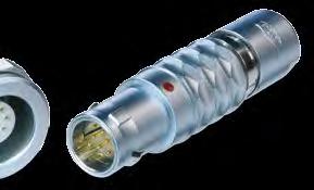


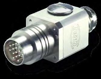


131 Company Information Page 131 Company Information


132 Quality Management ODU has had a powerful quality management system in place for years. ODU has been successfully certified to ISO 9001 since In addition, the automotive sector of the company group is certified to ISO TS The certification process was carried out by the internationally active BVQI (Bureau Veritas Quality International) company. ODU is also certified according to the medical standard ISO : AC : Additional to this ODU is certificated to DIN EN ISO : 2009 as well as to different certifications: VDE, UL, UL wiring harness, SCA, VG, MIL. Company Information Page 132


133 Your Partner in Many Application Areas ODU stands for quality, flexibility and reliability. This is why customers working in many application areas rely on ODU products in markets such as the following: Medical Industrial Measuring and testing Military and security Energy Automotive. Page 133 Company Information


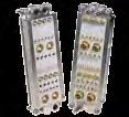
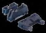

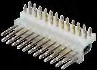
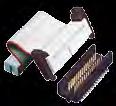

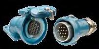


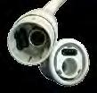

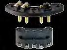
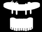
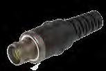
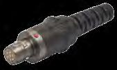

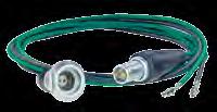

134 The Complete ODU Product Range Single contacts (round or flat) High current connectors Circular connectors with Push-Pull locking Modular rectangular connectors PCB connectors Robust connectors Disposable Systems Application specific solutions AMC Advanced Military Connector Cable assembly Company Information Page 134

135 Everything From One Source Each connection needs its individual cable. Make no compromises when it comes to the quality of the complete connection system. ODU gives you the complete system solution from one source, with no intermediary suppliers. Cable assembly is a very complex subject. It requires equal measures of expertise in the areas of connectors, cables and assembly. ODU meets all these requirements in full. Our competent assembly team tests the complete system according to your specifications. Our assembly service promises you the same quality found in our connectors without compromises. ODU offers you all from one source 100 % final inspections Production in clean room acc. to EN ISO possible Automatic processes (cutting, stripping, attaching) Extrusion possible with a hot-melt and high pressure/ temperature process Ultrasound welding EMC-compatible assembly Application specific labeling Widest range of potting possibilities for sealed systems Extruded cable crossovers. Advantages for the customer Modern manufacturing facilities in Mühldorf (Germany), Shanghai (China) and Sibiu (Romania) Reliability thanks to our company-wide quality strategy Products with durability and functional reliability Production according to UL (file: E333666) possible Inspections, such as crimp force monitoring, during production. Page 135 Company Information

136 Application Specific Connectors Innovative, dynamic markets call for innovative connectors. As an expert for special applications and requirements, we develop forward-looking, appropriate connectors attuned to your needs! In spite of the global trend toward standardized connectors, there are always applications that call for an application specifi c solution. We accept this challenge and develop innovative products for our customers based on our many years of extensive know-how, our creativity and, not least, our high level of vertical integration. Technology access and technology mastery, combined with intensive cooperation with the user, form the basis for achieving success together. Design-to-cost is joined by design-for-application for the customer s benefit. Company Information Page 136
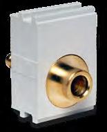
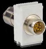
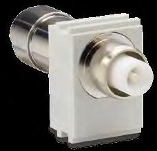

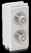
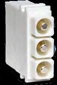

137 Order Information Page 137 Order Information
138 Order Information Module Overview for ODU-MAC in the DIN housing and ODU-MAC in the aluminium frame Description Units Page Module number 10 positions for turned contacts Description Units Page Module number 2 positions for 75 Ω coaxial contacts positions for stamped contacts Module for 2 compressed air valves positions for turned contacts Module for 1 compressed air valve positions for turned contacts Module for 2 compressed air valves positions for turned contacts Module for fluid coupling plug positions for turned contacts positions for turned contacts positions for turned contacts positions fibre-optic contacts for plastic fibre 5 positions fibre-optic contacts for plastic fibre 3 positions fibre-optic contacts for fibre-glass positions high voltage module with turned contacts Module for multi-position, shielded implementation, insert size positions power module with turned contacts Module for multi-position, shielded implementation, insert size positions power module ODU LAMTAC with turned contacts Module for multi-position, shielded implementation, insert size positions power contacts ODU SPRINGTAC with turned contacts Module for multi-position, shielded implementation, insert size position power contact ODU LAMTAC Empty modules 1, 3, position for high voltage contacts Coding modules positions for 50 Ω coaxial contacts non-magnetic Pin protection modules positions for 50 Ω coaxial contacts positions for 50 Ω coaxial contacts SMA termination Order Information 2 positions for 50 Ω coaxial contacts high voltage, non-magnetic Page
139 Order Information Frame sizes ODU-MAC in the DIN housing Frame sizes ODU-MAC in the aluminium frame Please set up an ODU-MAC in a DIN housing according to your specifications with the help of the module numbers and the depictions. Please set up an ODU-MAC in an aluminium frame according to your specifications with the help of the module numbers and the depictions. Size 1 10 units Size 2 16 units Max. 60 units Size 3 24 units Size 4 34 units Pitch: 2.54 mm = 1 unit Pitch: 2.54 mm = 1 unit Page 139 Order Information

140 2 rue René Laennec Taissy France Fax: , Tel : hvssystem@hvssystem.com Site web : Stand: 2013/ b-Katalog-MAC_e Produktion: KOMMA Werbeagentur GmbH
ODU DOCK and ODU ROB. Connectors for Docking and Robot Systems.
 and ODU ROB Connectors for Docking and Robot Systems Robust Circular Connectors and ROB Applications Industrial robots Tool change and depot systems Cable connections for robot systems Test equipment Features
ODU-MAC. Modular Connector System with High Power, Signal, Coaxial and fiber optic contacts, pneumatic modules
 Catalogue No. 100-c ODU-MAC Modular Connector System with High Power, Signal, Coaxial and fiber optic contacts, pneumatic modules ODU-Steckverbindungssysteme GmbH & Co. KG, Pregelstraße 11, D-85 Mühldorf/Inn
ODU MAC LC. Modular Attachable Connector System
 Catalogue No. 1004 LC-a ODU MAC LC Modular Attachable Connector System ODU Steckverbindungssysteme GmbH & Co. KG, Pregelstr. 11, 84453 Mühldorf a. Inn, Germany Phone: +49/ 86 31/61 56-0, Fax: +49/ 86 31/61
ODU MAC. Modular Connector System with High Power, Signal, Coaxial and fiber optic contacts, pneumatic modules
 Catalogue No. 1004-d ODU MAC Modular Connector System with High Power, Signal, Coaxial and fiber optic contacts, pneumatic modules ODU Steckverbindungssysteme GmbH & Co. KG, Pregelstraße 11, D-84453 Mühldorf/Inn
ODU MAC LC. Modular Attachable Connector System. 2 rue René Laennec Taissy France Fax: , Tel :
 Modular Attachable Connector System 2 rue René Laennec 51500 Taissy France Fax: 03 26 85 19 08, Tel : 03 26 82 49 29 E-mail:hvssystem@hvssystem.com Site web : www.hvssystem.com Modular Attachable Connector
D-Sub SEaled subminiature D connectors, 2.54 mm pitch
 SE D-Sub SEaled subminiature D connectors, 2.54 mm pitch Page Technical characteristics.......................................... 02 IP 67 versions with turned solder cups......... 04 IP 67 versions with
Han-Brid. Contents Han-Brid Features Han-Brid Data interfaces Han-Brid Overview Han-Brid Cu
 Contents Page Features... 19.02 Data interfaces... 19.03 Overview... 19.04 Cu... 19.06 F.O.... 19.08 Quintax 3 A... 19.10 RJ45 C... 19.12 USB / FireWire... 19.14 Han 4 A SC... 19.16 Hoods/Housings... 19.18
ODU MINI-SNAP PC Product Description. ODU MINI-SNAP PC: The Connector with Push-Pull-Locking in Plastic
 ODU MINI-SNAP PC Product Description ODU MINI-SNAP PC: The Connector with Push-Pull-Locking in Plastic Cylindrical Connectors are generally available with several locking mechanisms: The most frequently
Applications
 Han PCB adapter Contents Page Technical characteristics PCB adapter for Han DD... 20.02 Han DD Inserts with PCB adapter... 20.03 Technical characteristics PCB adapter for Han E... 20.04 Han E Inserts with
ODU-MAC A PERFECT ALLIANCE. AUTOMATIC DOCKING MANUAL MATING SHORT OVERVIEW
 A PERFECT ALLIANCE. ODU-MAC Compact modular connector system. Up to,00 V, 0 bar, 0 Gbit/s, 00,000 mating cycles and 9.0 GHz. AUTOMATIC DOCKING MANUAL MATING SHORT OVERVIEW ODU-MAC SILVER-LINE ODU-MAC WHITE-LINE
ODU-MAC A PERFECT ALLIANCE. AUTOMATIC DOCKING MANUAL MATING SHORT OVERVIEW
 A PERFECT ALLIANCE. ODU-MAC Compact modular connector system. Up to 6,00 V, 0 bar, 0 Gbit/s, 00,000 mating cycles and 9.0 GHz. AUTOMATIC DOCKING MANUAL MATING SHORT OVERVIEW ODU-MAC SILVER-LINE ODU-MAC
Han PCB termination. Han-Fast Lock PCB adapter for Han DD PCB adapter for Han DDD module
 Han termination Contents Page Han-Fast Lock... 20.11 adapter for Han DD... 20.13 adapter for Han DDD module... 20.16 adapter for Han 40 A Axial module... 20.18 adapter for Han E... 20.20 adapter for Han
Clarke & Severn Electronics Ph
 Clarke & Severn Electronics Ph +612 9482 1944 Email: sales@clarke.com.au www.clarke.com.au www.cseonline.com.au A perfect alliance. ODU-Mac Compact modular connector system. Up to 6,300 V, 20 bar, 10 Gbit/s,
07. har-link Interface Connectors
 . Interface Connectors The highest data rates in combination with perfect shielding characterize the connector. This way data can be passed on optimally within the control cabinet. The locking mechanism
VMEbus systems System description Technical characteristics System description
 Directory chapter 06 / inverse Page VMEbus systems................................................ 06.02 System description.............................................. 06.03 Technical characteristics..........................................
SUNCLIX Connection technology for photovoltaics
 SUNCLIX Connection technology for photovoltaics Connection technology for photovoltaics Are you looking for innovative and reliable connection technology for your PV modules, inverters or the complete
Mating Interfaces 1,63 (.064) 3,45 (.135) Ø3,71 (.146) MAX Ø6,61 (.260) MAX Ø3,71 (.146) MAX
 3,45 (.135) Ø3,71 (.146) MAX Ø6,61 (.260) MAX Ø3,71 (.146) MAX") SMB / SMC Cannon's SMB Snap-on and SMC Screw-on subminiature coaxial connectors have been specifically engineered for high performance and high reliability applications in both military and commercial
SMB / SMC Cannon's SMB Snap-on and SMC Screw-on subminiature coaxial connectors have been specifically engineered for high performance and high reliability applications in both military and commercial
Cannon 50 Ohm Connectors
 SMB / SMC Cannon's SMB Snap-on and SMC Screw-on subminiature coaxial connectors have been specifically engineered for high performance and high reliability applications in both military and commercial
Han R 23. Circular Connector. Certified acc. to DIN EN ISO 9001 in design/ development, production, installation and servicing.
 Circular Connector Certified acc to DIN EN ISO 9001 in design/ development, production, installation and servicing Data Sheet 0039-4 Circular Connectors Features Size R 23 Outer diameter 26 mm High contact
Operating voltages up to 40 kvdc Operating current up to 30 Amps Advanced contact technology Silver plated and gold plated contacts available High
 Operating voltages up to 40 kvdc Operating current up to 30 Amps Advanced contact technology Silver plated and contacts available High performance insulation material General characteristics and technical
Details of the Han-Terminal block connector Han D AV Han D AV Distributor Han E AV Han ES AV
 Contents -Terminal Block Connectors Page Details of the -Terminal block connector........................ 08.02 D................................................... 08.10 D Distributor...........................................
07. har-link INTERFACE CONNECTORS
 . INTERFACE CONNECTORS The highest data rates in combination with perfect shielding characterize the connector. This way data can be passed on optimally within the control cabinet. The locking mechanism
Description of parts Panel mounting Insert mounting without/with Carrier element Plastic housings
 - Contents Page Features -... 11.02 Component range -... 11.03 Description of parts... 11.04 Latching parts without/with Strain relief and Panel mounting parts... 11.06 Panel mounting... 11.08 Insert mounting
Extract from new. Device Connectivity catalogue. HARTING har-flex. People Power Partnership
 Extract from new Device Connectivity catalogue HARTING har-flex People Power Partnership . har-flex CONNECTORS The continuous scalability by an even number of contacts, i.e. from 6 to 100, of the HARTING
07. har-link Interface Connectors
 . Interface Connectors The highest data rates in combination with perfect shielding characterize the connector. This way data can be passed on optimally within the control cabinet. The locking mechanism
ODU-MAC A PERFECT ALLIANCE. MANUAL MATING AUTOMATIC DOCKING SHORT OVERVIEW
 A PERFECT ALLIANCE. ODU-MAC A new performance class. Up to 2,00 V, 2 bar, 0 Gbit/s, > 0,000 mating cycles and 4.0 GHz. MANUAL MATING AUTOMATIC DOCKING SHORT OVERVIEW ODU-MAC BLUE-LINE ODU-MAC SILVER-LINE
ODU-MAC A PERFECT ALLIANCE. MANUAL MATING AUTOMATIC DOCKING SHORT OVERVIEW
 A PERFECT ALLIANCE. ODU-MAC A new performance class. Up to 2,00 V, 2 bar, 0 Gbit/s, > 0,000 mating cycles and 4.0 GHz. MANUAL MATING AUTOMATIC DOCKING SHORT OVERVIEW ODU-MAC BLUE-LINE ODU-MAC SILVER-LINE
09. DIN Connectors
 . Connectors Connectors that comply with have been in use for years for both board-to-board applications and cable-to-board applications. Their robustness and universality are legendary. The classic signal
Hypermod Series. Heavy Duty Modular Connectors. Technical Characteristics
 Heavy Duty Modular Connectors Heavy duty modular rectangular connector for signal, power, fiber optics, databus and coaxial contacts. From 1 mm to 3.5 mm nominal pin DIA crimp contacts; 3, 5, 10 and 20
M12 Field Wireable Connectors. M12 CAT.6A Field Wireable Connectors. M12 Field Wireable Connectors for PROFINET
 M12 Connectors Application Advantage Shielded design ETHERLINE Ethernet Cable, Connectors & Tools M12 Field Wireable Connectors Male Female Temperature Range: Max. 85 C Nominal Voltage: Nominal Current:
CONTA-ELECTRONICS. Interface modules
 CONTA-ELECTRONICS allow for a passive mechanical-electrical implementation of standard connectors onto screw or tension-spring PCB terminals. The individual signals of the multi-pole or high-pole connectors
Right angle press-fit D-Sub connectors
 Right angle press-fit D-Sub connectors Version in Standard and in Eurostyle General The new generation of right angle D-Sub connectors with press-fit termination of the TMC series are according to DIN
M12 connector D-coding M12 connector X-coding RJ45 IP20 connector PushPull RJ45 IP65 / IP67 connector
 M12 connectors Directory Chapter Page General information....02 M12 connector D-coding....06 M12 connector X-coding....20 RJ45 IP20 connector....27 PushPull RJ45 IP65 / IP67 connector....46 Han 3 A RJ45
V.35 - Interface connectors
 V.35 DTE/DCE Interface connectors Description The Telecommunications Standardization Sector TSS V.35, formerly CCITT V.35 is the international standard termed Data Transmission at 48 Kbps using 60-108
Directory chapter 05. D-Sub Filter subminiature D connectors, 2.54 mm pitch
 F Directory chapter 05 D-Sub Filter subminiature D connectors, 2.54 mm pitch New Page General information.............................................. 05.02 Technical characteristics..........................................
ODU-MINI-SNAP. Series S - IP50 and IP68 FP-Locking Concept Keying with Insulation Body. Series S
 OU-MINI-SNAP Series S - IP and IP68 FP-Locking Concept Keying with Insulation Body Series S OU-MINI-SNAP Series S The Push-Pull Locking Principle: FP Locking roove Conical Sleeve Locking Fingers Outer
Summary of shell housings and accessories Shell housing A Shell housing D EMC housing
 Directory chapter 20 Page Summary of shell and accessories........................... 20.02 housing C.......................... 20.04 housing A................................................. 20.08 housing
Data sheet... OMNIMATE Power - series BL/SL 7.62HP BLZ 7.62HP/04/180LR SN BK BX
 Power on board #96 100% safety, 100% integration, 100% cost-effectiveness: The compact and efficient solution for UL-600V applications in the lower performance range (up to 12 kva). 29 A at 400V (IEC)
Electrical Components Catalog Universal MATE-N-LOK Connector System
 Introduction Product Facts Pins and sockets can be intermixed in the same housing Positive polarization Rear cavity identification Contacts completely enclosed in housings Positive locking housings Insulation
EN3 SERIES WEATHERTIGHT CONNECTORS NEW PRODUCT BULLETIN 602
 FEATURES & BENEFITS Sealed to IP68 NEMA 250 (6P) Patented grommet & o-ring free design Available in ribbed or winged coupling ring Cable, panel & cable to cable options Gold plated contacts standard Solder,
Data sheet. HDC insert HDC HQ 7 FC
 The HQ series - big features in a compact design The electrical values speak for themselves. The standard HE crimp contacts can also be used here. The wire connection level is designed as a crimp contact
SEPTEMBER C.CS.1000 / GB
 SEPTEMBER 2005 - C.CS.1000 / GB C R I M P F L E X C O N N E C T O R S CRIMPFLEX connectors TECHNICAL DATA MATERIAL Phosphor bronze MALE SOLDER TAB PLATING The standard connector is tin plated (thickness
SMA Series. Specification. Description. Applications Civil & Military Telecommunication Instrumentation SMA SMA. Interface Mating Dimensions
 Series Specification 50 ohm 0-18 GHZ connectors are adaptable to interconnection requirements of both systems and components. S-Conn offers a wide variety of cable connectors, receptacles, feed thrus,
M23 Connectors and cables
 Contents Product Description: SAI M23 Connectors.2 Contact assignment.7 Technical data.8 Overview.10 M23 connector for signal transmission.12 M23 connector for power transmission.18 Moulded M23 cables.22
Our Most Important Connection is with You. SECTION 3. Board-to-Board: MMBX / SMP-MAX R223 / R222M
 SECTION 3 Board-to-Board: MMBX / R223 / R222M Contents MMBX Introduction... 3-4 Interface... 3-5 Characteristics... 3-6 Plugs... 3-7 PCB receptacles... 3-7 to 3-8 Adapters... 3-9 Demo board... 3-10 Panel
Dura-ConTM Hermetic Connectors
 Dura-ConTM Hermetic Connectors Standard Connectors With High Performance Hermetic Seals Catalog cinch.com Cinch Dura-Con Hermetic Connectors offers a high performance hermetic seal designed into our standard
2.54 mm Single Row Connector (SRC) MaxiBridge.
 MaxiBridge.") 2.54 mm Single Row Connector (SRC) www.erni.com Katalog Catalog D E 074591 074518 02/10 Ausgabe 3, 03/05 Edition www.erni.com 7 1 www.erni.com Catalog E 074591 02/10 Edition 7 Table of Contents General..............................................................................................2
2.54 mm Single Row Connector (SRC) www.erni.com Katalog Catalog D E 074591 074518 02/10 Ausgabe 3, 03/05 Edition www.erni.com 7 1 www.erni.com Catalog E 074591 02/10 Edition 7 Table of Contents General..............................................................................................2
Connectors. product catalog no. 26
 Connectors product catalog no. 26 ept GmbH I Tel. +49 (0) 88 61 / 25 01 0 I Fax +49 (0) 88 61 / 55 07 I E-Mail sales@ept.de I www.ept.de Product Groups Overview Explanation of Symbols Termination Application
D-SUBMINIATURE (D-SUB) ECONOMY RANGE CONNECTORS
 ECONOMY RANGE CONNECTORS") INPUT/OUTPUT CONNECTORS D-SUBMINIATURE (D-SUB) OVERVIEW FCI s D-Subminiature (D-Sub) connectors are part of an industry standard for applications requiring robust and reliable connectors. These proven
INPUT/OUTPUT CONNECTORS D-SUBMINIATURE (D-SUB) OVERVIEW FCI s D-Subminiature (D-Sub) connectors are part of an industry standard for applications requiring robust and reliable connectors. These proven
CIRCULAR CONNECTORS A PERFECT ALLIANCE. HIGH-QUALITY SOLUTIONS MADE OF METAL & PLASTIC SHORT OVERVIEW
 A PERFECT ALLIANCE. CIRCULAR CONNECTORS Maximum performance and reliability to fit the smallest available space a solution made to measure! HIGH-QUALITY SOLUTIONS MADE OF METAL & PLASTIC SHORT OVERVIEW
ME PLC Multifunctional housing for complex electronics. Data sheet _en_01. 1 Description
 Multifunctional housing for complex electronics Data sheet 105504_en_01 PHOENIX CONTACT 2013-04-08 1 Description The housings of the ME PLC 40... product group consist of a 40-mm wide housing base with
Technical Data, 4-way High Voltage. Cannon APD / ISO Connectors. Electrical Data. Mechanical Data. Materials List
 Technical Data, 4-way High Voltage APD 4-way connectors are the original DIN72585 (now ISO 15170) versions using a 2,5 mm contact system. Designed for automotive applications they also meet the requirements
Panel-to-Wire / Board-to-Wire, Crimp and Solder Connection Lever Mating Type Rectangular Connector with EMI Countermeasure QE6 Series
 COMPONENTS PRODUCT INFORMATION RoHS Compliant NEW Panel-to-Wire / Board-to-Wire, Crimp and Solder Connection Lever Mating Type Rectangular Connector with EMI Countermeasure QE6 Series CONNECTOR MB-0281-3
HARTING News 2007
 98 42 914 0201 HARTING News 2007 People Power Partnership Quality Connections Worldwide HARTING was founded in 1945 by the family that still owns the company. Its headquarters are situated in Espelkamp,
Automotive Camera Module RF Connector POK15 Series
 Features 1. Superior locking mechanism Our exclusive locking method keeps the mating part in constant contact with the electric reference plane(top Touch), ensuring high contact stability and reliability.
Series PC 3.5 precision subminiature connectors
 Series PC 3.5 precision subminiature connectors Description Content HUBER+SUHNER PC 3.5 connectors are precision connectors for use in microwave applications up to 26.5 GHz. They are especially suitable
Technical data: Pin Spacing
 282 Female Connectors, Double-Row Pin Spacing: 3.5 mm Universal connection for all conductor types Unique, compact, double-row connector system for conductor cross sections up to 1.5 mm 2 High-density,
Connect - Contact - Control. Connectors according to UIC VE EP Series. F 121.en
 Connect - Contact - Control Connectors according to UIC 541-5 VE 123 F 121.en 2 Connector to UIC standard 541-5 VE, The connector is designed in accordance with the specifications of the international
 N Series Connectors Medium sized connector for high-voltage applications Suited for critical applications and environments Performance to 11 GHz (commercial) and 18 GHz (hi frequency) Intermateable with
Data sheet. HDC insert HDC HQ 5 FC
 A small unit that packs a big punch. The electrical values speak for themselves. Proven HE crimp contacts can also be used here. Number of poles: 5 (+PE) Rated current: 16 A Rated voltage: 250 V Rated
Transforming customer wishes into concrete solutions
 HARTING News 2013 HARTING worldwide Introduction Transforming customer wishes into concrete solutions The HARTING Technology Group is skilled in the fields of electrical, electronic and optical connection,
Series 801 Mighty Mouse Double-Start ACME Thread Plug
 Series 0 Mighty Mouse ouble-start ACME Thread Plug 0-00 and 0-00 Ordering Information Series 0 Series 0 Mighty Mouse Connector features a double-start modified stub ACME mating thread for improved protection
IDC Assembly (depends on cable) -55/125 C. IDC Assembly (depends on cable) By ambient temperature: 20 C 1,2 A 70 C 0,9 A 100 C 0,6 A
 -55/125 C. IDC Assembly (depends on cable) By ambient temperature: 20 C 1,2 A 70 C 0,9 A 100 C 0,6 A") mm Connectors Surface Mount Technology, Solderless Pressfit, IDC Electrical And Mechanical Characteristics Number of Pins Technical data Climate Category Bearing and operating temperature area Current
mm Connectors Surface Mount Technology, Solderless Pressfit, IDC Electrical And Mechanical Characteristics Number of Pins Technical data Climate Category Bearing and operating temperature area Current
UTS UTS. UTS provides a connection that performs faster, easier, safer and more reliable, it makes :
 Company Profile UTS Contents Company profile... 2 Contents... 3 Description... 3 Overview TRIM TRIO... 4 Major features & benefits 5-9 Contact styles... 5 Rapid and secure locking system... 6 Rapid and
Prices, specifications, statement of warranty, and other terms and conditions are subject to change without notice by Lighthorse Technologies, Inc.
 Section Index Connectors Specifications... 93 Flexible Cable... 95 Panel Mount... 99 Bulkhead... 100 PCB Mount... 101 In Series Adaptors... 103 Other Information Assembly Instructions... 176 Cable Assembly...
ODU-MAC in the Aluminium Frame
 ODU-MAC ODU-MAC in the The ODU-MAC in the aluminium frame is used exclusively for automatic docking. For manual mating, see ODU-MAC in the DIN housing, starting on page 91. Page 83 Part Number System for
SYSTEM CONNECTORS FOR W-CDMA
 SYSTEM CONNECTORS COMPLINT WITH EIJ RC-5238 (CONNECTOR FOR IMT-2000 MOBILE PHONES) SYSTEM CONNECTORS FOR W-CDM Receptacle Signal 10 contacts with coaxial, with charging terminals ( type) Plug Signal 10
02. PushPull CONNECTORS
 . CONNECTORS A distributed automation system does not contain any central automated control cabinets. Controls, sensors and actuators are designed for a high degree of protection (IP 65 / IP 67) and are
High Reliability Rectangular Plastic Connector
 High Reliability Rectangular Plastic Connector The REP connector is a multi pole IP66 sealed rectangular plastic connector which provides a quick, reliable and easy connection in all electronic applications.
Ethernet cabling. B Ethernet cabling. Ethernet cabling overview B 2. Cabling 4-poles IP 20 B.1 8 IP 65 / IP 67 B Cables B Tools B.
 Ethernet cabling Contents Page B Ethernet cabling Ethernet cabling overview B 2 Cabling 4-poles B.1 8 B.1 22 Cables B.1 96 Tools B.1 104 Cabling 8-poles B.2 8 B.2 20 Cables B.2 90 Tools B.2 98 B 1 Profile
Better all-round. DataVoice Circular connectors STX M12x1 IP67 Connector series for industrial applications. PoE+ 10 GBE. coded.
 Better all-round. X coded D coded 10 GBE PoE+ DataVoice Circular connectors STX M12x1 IP67 Connector series for industrial applications STX M12x1 IP67 connector series With the STX M12x1 IP67 connector
SERIES MCX 50 MICRO MINIATURE CONNECTORS
 SERIES MCX 50 MICRO MINIATURE CONNECTORS DESCRIPTION CONTENT PAGE HUBER+SUHNER MCX micro miniature snap-on connectors offer you an excellent blend of size, weight, durability and performance for applications
revos revos Industrial Multipole Connectors
 revos revos Industrial Multipole Connectors Catalog 2018 revos MINI Plant II, Rodezstraße in Bamberg Company headquarters in Bamberg STOCKO main plant in Wuppertal Solutions for Building technology AT
TNC SERIES Miniature Coaxial Connectors
 SERIES Miniature Coaxial Connectors FEATURES connectors, medium sized coaxial connectors with thread coupling, are designed for applications where extreme vibration is encountered.the increased rigidity
CRIMPFLEX connectors for flexible circuits
 CRIMPFLEX connectors for flexible circuits CRIMPFLEX CONNECTORS Technical data...3 CRIMPFLEX CRIMPING Description...4 MALE SOLDER TABS Solder tabs environment...5 Standard short male solder tab...6 Standard
CMC Hybrid Connectors Standard and Power Versions
 The Molex family of provides a sealed, high-density, modular and cost-effective connection system for heavy-duty, powertrain and body-electronics applications in the transportation industry The CMC connector
SMA Connectors. RF Coax Connectors. Product Facts
 SMA Connectors Product Facts Performance to 12.4 GHz and beyond Available in various base metal options, including stainless steel, brass and zinc diecast Uses industry standard crimp tools and processes
ODU High-Speed-Connections
 ODU High-Speed-Connections Satisfy All Standards and Set New Benchmarks www.odu.de Features That Have What it Takes: ODU develops functionally reliable connection solutions for well-known companies. The
ERNIPRESS Trapezoidal-Connectors Series TMC
 ERNIPRESS Trapezoidal-Connectors Series TMC Subminiatur-D Connectors to DIN 41 652/IEC 807-3 with Press-fit zone General Solderless press-in technology for connectors in bus systems permits rationalized
Introduction. The information pages provide standard data common to all D-subminiature connectors. These include:
 Connectors Information Introduction The D-subminiature is one of the most popular styles of connectors in the I/O category. It is used in computer, telecom, datacom, medical, and test instrumentation applications
02. PushPull CONNECTORS
 . CONNECTORS A distributed automation system does not contain any central automated control cabinets. Controls, sensors and actuators are designed for a high degree of protection (IP 65 / IP 67) and are
FISCHER MINIMAX TM SERIES
 TECHNICAL SPECIFICATIONS FISCHER TM SERIES Fischer Connectors SA All rights reserved Web version 1.0-03.2016 Changes without prior notice FISCHER TM SERIES KEY FEATURES The Fischer MiniMax Series increases
HARTING Connectors for High Mating Cycles
 HARTING Connectors for High Mating Cycles HARTING worldwide Transforming customer wishes into concrete solutions The HARTING Technology Group is skilled in the fields of electrical, electronic and optical
Small Circular Connector. JN1/JN2 Series. Cap
 COMPONENTS PRODUCT INFORMATION RoHS Compliant NEW Small Circular Connector JN1/JN2 Series CONNECTOR MB-0054-10 June 2012 Angle Plug [JN1] [JN2] [JN1] [JN2] Straight Plug Cable Connecting Individual Plug
Universal MATE-N-LOK Connectors
 Product Facts Pins and sockets can be intermixed in the same housing Positive polarisation Rear cavity identification Contacts completely enclosed in housings Positive locking housings Insulation capability
Accessories Cassette Style Mating Connectors
 Description All 19" cassette style converters are equipped with either H11, H15, H15S4, or H15S2 male connectors. Mating female connectors are available as accessories. The four H- type connector versions
Ringlock is a range of robust circular
 Connectors is a range of robust circular connectors for industrial applications. It uses a metal bayonet coupling system for quick and reliable connections and thermoplastic bodies for low installed cost.
SMA - 50 Ohm Connectors
 Alphabetical Index 142-0701-201 4 142-0701-206 4 142-0701-231 4 142-0701-235* 4 142-0701-236 4 142-0701-301 5 142-0701-306 5 142-0701-335* 6 142-0701-421 5 142-0701-426 5 142-0701-491 5 142-0701-496 5
INCHES (MILLIMETERS) CUSTOMER DRAWINGS AVAILABLE ON REQUEST
 CUSTOMER DRAWINGS AVAILABLE ON REQUEST") TNC Connectors Flexible Cable... 3 In-Series Adapters... 4 Specifications... 2 RF Adapter Kit Adapters... 6 N Connectors Panel Mount and In-Series Adapters... 10 Flexible Cable... 8 Specifications... 7
TNC Connectors Flexible Cable... 3 In-Series Adapters... 4 Specifications... 2 RF Adapter Kit Adapters... 6 N Connectors Panel Mount and In-Series Adapters... 10 Flexible Cable... 8 Specifications... 7
D-Series High Reliability Circular Connectors
 D-Series High Reliability Circular Connectors Technology Company, Inc. integramate D-Series Circular Connectors QA Technology integramate D-Series Connectors are high quality, plastic circular connectors
ADVANCED CONNECTOR SOLUTIONS
 A PERFECT ALLIANCE. ADVANCED CONNECTOR SOLUTIONS CIRCULAR CONNECTORS ELECTRICAL CONTACTS MODULAR / RECTANGULAR CABLE ASSEMBLY ODU CONNECTIVITY SOLUTIONS AND CAPABILITIES A PERFECT ALLIANCE. ODU MINI-SNAP
IP68 Sealed - Mini USB Buccaneer
 IP68 Sealed - IP68 Over moulded assembly provides IP68 cable seal Coupling ring, screw thread provides secure cable coupling Mini USB connector O ring maintains IP68 seal at connector interface Mini USB
Data sheet. OMNIMATE Signal - series B2L/S2L row S2L-SMT 3.50/08/180G 3.5SN BK BX
 OMNIMATE Signal - series /S2L 3.50-2-row High-temperature-resistant, straight, 2-tier male connector for all common soldering methods. Optimised for automatic assembly. Packed in box or tape. 3.2 mm solder
SMP / SMP-COM / SMP-MAX series R222
 3 SMP / SMP-COM / SMP-MAX series R222 SMP-MAX INTRODUCTION BOARD TO BOARD SOLUTIONS The Best Systems Radiall s engineers work with your engineers allowing us to develop the best competitively priced misalignment
Standard Buccaneer BUCCANEER FOR POWER
 IP8 rating tested at 1.05kg/sq cm (15lb/sq in) 10m depth for weeks and.8kg/sq cm (10lb/sq in) 100m depth for hours IPK, Tested in accordance with DIN 0050/Part IPkk Water and dustproof to IP8 when mated,,,,,,
HARTING. News People Power Partnership
 98 42 914 0201 HARTING News 2011 People Power Partnership H A R T I N G w o r l d w i d e Transforming customer wishes into concrete solutions 2 The HARTING Technology Group is skilled in the fields of
Through-Board SMD PCB Terminal Block; 0.75 mm² Pin Spacing: 6.5 mm 2070 Series
 Volume, Section SMD PCB Terminal Blocks Through-Board SMD PCB Terminal Block; 0.75 mm² 070 Series SMD PCB terminal blocks with Push-in CAGE CLAMP connection for back-side wiring of LED modules Low profile
EPIC Circular Connectors CIRCON M23 Series
 The M3 connectors have many inherent features which offer application advantages and provide significant benefits for the customer. These features make it one of the most application friendly connectors
Powermate Range pitch 10.16
 Contents owermate Range pitch.16 owermate Range pitch.16 owermate Range pitch.16 Male connectors with solder connection.2 Socket connectors with clamping yoke connection.8.1 owermate Range pitch.16 SU.16/9
REP SERIES High Reliability Rectangular Plastic Connectors
 REP SERIES High Reliability Rectangular Plastic Connectors Fire & Smoke standards compliance High Performance and safe connector Cost saving solution IP66 & IP67 sealing HIGH RELIABILITY The REP connector