spds-480ca Power / data supply for large-scale Ethernet installations
|
|
|
- Baldric Hardy
- 5 years ago
- Views:
Transcription


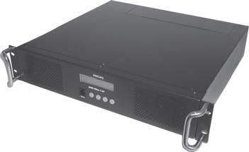
1 spds-480ca Power / data supply for large-scale installations
2 spds-480ca Power / data supply for large-scale installations spds-480ca is a power / data supply designed for large-scale LED lighting installations using low-voltage fixtures from Philips Color Kinetics. spds-480ca includes 7.5 V and 24 V versions to meet the power requirements of different fixtures. spds-480ca 24 V delivers 480 watts of output via eight 60-watt ports. The 7.5 V version delivers 480 watts of output via watt ports. Both automatically accommodate input voltages ranging from 100 VAC to 240 VAC. Short-circuit protection prevents device failure due to incorrectly wired fixtures. The standard IEC power inlet accepts both North American and international power cables. With onboard controls, spds-480ca incorporates automatic fixture discovery and testing, eliminating the need for additional addressing tools or software. spds-480ca features a backlit LCD for easy menu viewing. Compatible Fixtures Device spds-480ca 7.5 V spds-480ca 24 V Fixture Max. Quantity Per spds-480ca Max. Quantity Per Output Port icolor Flex MX 960 nodes 60 nodes icolor Tile MX 6 tiles 1/2 tile ew Flex SLX 480 nodes 60 nodes icolor Flex LMX 480 nodes 60 nodes icolor Cove EC 7 in 240 fi xtures 30 fi xtures icolor Cove EC 12 in 240 fi xtures 30 fi xtures icolor Cove QLX 6 in 240 fi xtures 30 fi xtures icolor Cove QLX 12 in 160 fi xtures 20 fi xtures Housed in a 2U rack-mountable enclosure, spds-480ca includes rack handles and surfacemount brackets, for versatile mounting options. Over-temperature detection and selectable shutdown options protect spds-480ca against operation beyond its rated temperature specification. Variable-speed fans keep noise levels low and include user serviceable air filters. Versatile Power and Data for Large-Scale Installations Provides power to up to 240 lowvoltage fixtures. Features include short-circuit protection, on-board controls, and diagnostic functions to assist with the proper operation of Philips Color Kinetics lighting systems. 2 spds-480ca Product Guide
3 spds-480ca 24V spds-480ca 24V LISTED 78GF Specifi cations Due to continuous improvements and innovations, specifications may change without notice. Item Specifi cation Details Electrical Physical Certifi cation and Safety Input Voltage Maximum Input Current Power Output Fuse Rating spds-480ca 7.5 V spds-480ca 24 V spds-480ca 7.5 spds-480ca 24 V Dimensions (Height x Width x Depth) Weight Construction Finish Connectors Data Temperature Ranges Humidity Cooling Airfl ow Heat Dissipation Data Input Source Certifi cation Classifi cation Environment Power Output Power Input VAC, auto-switching, 50 / 60 Hz 6 A at 100 VAC, 5 A at 120 VAC, 2.5 A at 240 VAC 7.5 VDC, 480 W (30 W per power port) 24 VDC, 480 W (60 W per power port) (16) 5 A, 125 V, 5 x 20 fast blow fuses (8) 4 A, 125 V, 5 x 20 fast blow fuses 3.5 x 19 x 18 in (89 x 483 x 457 mm) 26.5 lb (12 kg) 2U rack and surface-mountable chassis Black matte RJ45 input connector spds-480ca 7.5 V (8) 4-pin output receptacles spds-480ca 24 V (16) 4-pin output receptacles IEC 320 receptacle type C13, locking clamp F ( C) Operating F ( C) Startup F ( C) Storage 0 95%, non-condensing Air cooled. (2) speed-confi gurable fans, with serviceable air fi lters Front panel input, back panel output 25% of total power input Philips full range of controllers, or thirdparty KiNET-compatible* controllers UL / cul, CE, PSE UL Class 2 power supply Dry Location, IP20 * KiNET is the lighting protocol from Philips Color Kinetics in (312 mm) 10.6 in (269 mm) 1.8 in (46 mm) 2.9 in (74 mm) 17.0 in (432 mm) 19.0 in (483 mm) Dimensions: Rack Mount Configuration 16.4 in (417 mm) 1.8 in (46 mm) 3.0 in (76 mm) 2.3 in (58mm) 18.0 in (457 mm) 10.6 in (269 mm) 3.5 in (89 mm) 13.5 in (343 mm) Ordering Information Item Item Number Philips 12NC spds-480ca 7.5 V spds-480ca 24 V Use Item Number when ordering in North America in (467 mm) 19.0 in (483 mm) Dimensions: Surface Mount Configuration spds-480ca 24 V spds-480ca 7.5 V POWER/DATA 24VDC Power Switch POWER/D ATA 7.5VDC VAC, 6A - 2.5A, Hz 100 VAC T VAC 50Hz-60Hz, 8A Max. spds-480ca 24V ITEM# spds-480ca 7.5V ITEM# Fixture Leader Cables Menu LCD IEC Power Inlet and US Cable set Included in the box spds-480ca power / data supply (2) Rack mount bracket and handles spds-480ca 24V (2) Surface mount brackets (8) Screws, 0.7 X 10 mm to Switch Onboard Push-button Controls (8) Lock washers spds-480ca Product Guide 3
4 Installation spds-480ca is a power / data supply designed for large-scale LED lighting installations using low-voltage fixtures from Philips Color Kinetics. spds-480ca delivers 480 watts of output and automatically accommodates input voltages ranging from 100 VAC to 240 VAC. Onboard controls incorporate automatic fixture discovery, addressing, and testing. spds-480ca is available in 7.5 V and 24 V versions to meet the power requirements of different fixtures. Owner / User Responsibilities It is the responsibility of the contractor, installer, purchaser, owner, and user to install, maintain, and operate spds-480ca in such a manner as to comply with all applicable codes, state and local laws, ordinances, and regulations. Consult with the appropriate electrical inspector to ensure compliance. E Refer to the spds-480ca Installation Instructions for specifi c warning and caution statements. Plan the Installation To streamline installation and ensure accurate confi guration, start with a layout or a lighting design plan that shows the physical layout of the installation and identifi es the locations of all lighting fi xtures, power / data supplies, controllers, switches, and cables. Configuration spds-480ca is designed for use in networks. Typical installations with Philips Color Kinetics LED fixtures include an switch, an controller such as Light System Manager or Video System Manager Pro, Controller Keypads for light show triggering, and one or more spds-480ca devices. In an environment, each Philips Color Kinetics power / data supply has a unique IP address. Each fixture connected to the device is automatically assigned unique identifiers that controllers use to identify and manage the fixture. E To connect spds-480ca to a DMX Controller such as iplayer 3 or a third-party controller, use the Multi-Protocol Converter with a Power-over- (PoE) injector or PoE switch. icolor Flex MX Light System Manager Switch spds-480ca 7.5 V PC Typical Installation Maximum data cable lengths are 328 ft (100 m) between devices without a repeater. The number of fixtures that each spds-480ca unit can support depends on the power requirements of the specifi c fi xtures that you are using. See the table on the following page for the maximum quantities of each fi xture that you can connect per device. Switch 328 ft (100 m) Max PDS-480 ca 4 spds-480ca Product Guide
5 Compatible Fixtures Device spds-480ca 7.5 V Fixture Max. Quantity Per spds-480ca Max. Quantity Per Output Port icolor Flex MX 960 nodes 60 nodes icolor Tile MX 6 tiles 1/2 tile ew Flex SLX 480 nodes 60 nodes icolor Flex LMX 480 nodes 60 nodes spds-480ca 24 V icolor Cove EC 7 in 240 fi xtures 30 fi xtures icolor Cove EC 12 in 240 fi xtures 30 fi xtures icolor Cove QLX 6 in 240 fi xtures 30 fi xtures icolor Cove QLX 12 in 160 fi xtures 20 fi xtures Light System Manager Switch icolor Cove QLX Electrical Configuration Guidelines Linear fi xtures such as icolor Cove EC and icolor Cove QLX can be installed in series using the fi xtures end-to-end connectors. You can install one string of Flex fi xtures per port. icolor Tile MX requires two ports per fi xture for a total of eight tiles on a 7.5 V spds-480ca. Each spds-480ca connects to line power with a standard IEC inlet and power cable, which can be secured using a locking clamp located on the back of the device s housing. The spds-480ca should be installed in a dry location. PC spds-480ca 24V Typical icolor Cove QLX Installation E KiNET is the high performance network protocol engineered by Philips Color Kinetics for LED lighting control. Included in the box spds-480ca power / data supply IEC power cable (8) Lock washers (2) Rack mount brackets with handles (8) Screws, 0.7 X 10 mm (2) Surface mount brackets Assemble Additional Items The following items are required to mount and connect the spds-480ca: The 2 included rack mount brackets with handles (if rack mounting) 4 screws (typically 10-32) and lock washers suitable for mounting the device to a rack (if rack mounting) The 4 included surface mount brackets (if surface mounting) 16 screws suitable for the surface (if surface mounting) A power screwdriver (if surface mounting) A Phillips screwdriver (if surface mounting) The 8 included screws, 0.7 x 10 mm The 8 included lock washers The included IEC power cable CAT 5e or better data cable, as required You must also have access to a dedicated network, an switch, and a controller that is compatible with a KiNET-based lighting system, such as Philips Color Kinetics Light System Manager, Video System Manager Pro, or ColorDial Pro. Inspect spds-480ca and Accessories Carefully inspect the box containing the spds-480ca and the contents for any damage that may have occurred in transit. spds-480ca Product Guide 5
6 spds-480ca 24V spds-480ca 24V Mount the spds-480ca Make sure the device is powered OFF before mounting and connecting. You can rack mount the PDS-480ca or mount it to a vertical or horizontal surface. In either case, spds-480 must be installed in a location that allows air to move freely around the front and rear of the housing. Rack Mount You can mount the spds-480ca on a standard EIA-310-compliant rack. 1. Using the included mounting screws, attach one stainless steel handle to each pair of threaded holes located on either side of the device, just behind the faceplate. (Use two screws for each bracket.) 2. Each handle has two holes for rack mounting. Mount the device to a rack using four #10 or #12 machine screws and lock washers. E Make sure that there is adequate space to make all connections to the front and rear of the device. No vents should be facing down. E Make sure that the device is securely attached and free of excessive vibration. E If multiple devices are mounted on a single rack, leave at least 1 RU, or 1.75 in (44 mm), between each spds-480ca. Also, the rack should be located in an environment with a controlled climate in (432 mm) Surface Mount A power screwdriver is recommended for surface mounting. 1. Remove the included rack mount handles from their two attached brackets using a Philips screwdriver. Together with the other two included brackets, you will now have four brackets for surface mounting in (417 mm) 18.0 in (457 mm) 2. Using two included screws and lock washers for each bracket, attach two mounting brackets to each side of the device. The portion of each bracket with four holes should be fl ush with the bottom of the device. 2. Each of the included mounting brackets mount to the surface using 4 screws each. Mount the device to the surface using 16 screws that are suitable for the mounting surface in (483 mm) 1.8 in (46 mm) 3.5 in (89 mm) Dimensions: Rack Mount Configuration 12.3 in (312 mm) 10.6 in (269 mm) 13.5 in (343 mm) 10.6 in (269 mm) 1.8 in (46 mm) 3.0 in (76 mm) 2.9 in (74 mm) 2.3 in (58mm) 18.4 in (467 mm) 19.0 in (483 mm) Dimensions: Surface Mount Configuration 6 spds-480ca Product Guide
7 Connect the spds-480ca to Line Power 1. Connect the IEC power cable to the inlet in the back of the spds-480ca. 2. To secure the cord, tighten the locking clamp around the inlet with a Phillips screwdriver. 3. Connect the power cable to line power. Connect the spds-480ca to Fixtures Make sure the device is powered OFF before connecting to fixtures. 1. Connect the leader cables or Flex strands to an available port on the back of the device. Ports are labeled 1 through Power the device ON. E You can download QuickPlay Pro from addressing/ Note that before you can control the connected fixtures, you must discover fixtures using either the spds-480ca device s on-board menu (described in the next section), QuickPlay Pro software, or the discover functionality in the software for Light System Manager or Video System Manager. Discovering fi xtures fi nds the quantity of connected fi xtures and registers them on your power / data supply. spds-480ca Product Guide 7
8 Using the spds-480ca On-Board Menu spds-480ca has a navigable LCD screen with three menu levels. Menu Level View Status Configure NET: IP Address... MAC Address Description Displays device s current IP address Displays device s MAC address Network Displays an estimate of network bandwidth currently Data Rate used by the device Serial Number Displays the device s serial number Lights Lights Per Port Displays the nodes scanned for each port Temperature Internal Temp Min / Max Temp Fan Status Displays an estimate of the device s internal temperature Displays minimum and maximum temperature since device was last turned on Displays whether fan is on or off, and speed of fan as percentage of maximum Set IP Address 10.X.X.X Modifies the device s IP address Scan Lights Press Select Discovers and counts the nodes connected to each port Fan Settings Thermal Settings LCD Backlight Restore Defaults Low Medium High Auto* Turn Lights Off* Ramp Down Lights Stay On Bright Medium* Dim Auto-Dim Press Select Sets fans to run continuously at the selected speed. If temperature rise is detected, fan speed automatically switches to High until the temperature reaches a safe level. Fan speed automatically adjusts based on the detected temperature If device overheats, lights turn off If device overheats, lights smoothly fade out If device overheats, lights remain on Sets the brightness of the device s LCD backlight Dims the LCD backlight when no buttons have been pressed for 15 seconds Restores factory default settings for LCD Backlight, Fan Settings, and Thermal Settings. Network configuration is unaffected. spds-480ca 7.5 V To navigate the on-board menu: Press the Up and Down buttons ( ) to move up and down in the current menu s set of options. Press the Select button ( ) to select a menu item or display its submenu. Press the Cancel button ( ) to return to the previous menu level. Test Test Lights All Off All Red All Green All Blue All White Rainbow Single Port Turns off all nodes Turns on all channels of a particular color Cycles through red, green, and blue, showing waves of different colors across all nodes Turns on nodes connected to one port. Press Select to begin test. Press the Down button to begin automatically cycling through the device s ports. Press the Down button again to manually cycle through the device s ports. Turns on a single node. Press Select to begin test. Press Single Light the Down button to begin automatically cycling through the connected nodes. Press the Down button again to manually cycle through the connected nodes. Test Fans on Full Turns on the device s two fans at full speed Reset System About * Default settings. Press Select Press Select Resets the device. This has the same effect as powering it down and turning it back on. Your configured settings are unaffected. Displays system information, including unit model, serial number, and firmware revision number 8 spds-480ca Product Guide
9 E A node is an individually controllable fixture, or fixture segment, on your lighting network. Fixtures have one or more controllable nodes, depending on the fixture type. E For more on fi xture discovery and addressing, refer to the Addressing and Confi guration Guide available online at www. colorkinetics.com/support/ addressing/ Scanning Lights You can scan the nodes attached to the device s ports to discover fi xtures and confi rm that they are connected and receiving data. The discovery determines the quantity of connected nodes and registers them on your power / data supply. The power / data supply then assigns DMX addresses to uniquely identify each node, which controllers can use to perform video and light shows. To scan lights: 1. Press Select to activate the spds-480ca menu. 2. Select Confi gure. 3. Select Scan Lights. The LCD menu displays scanning When scanning fi nishes, you can confi rm that your light fi xtures are successfully connected by using the Up and Down buttons to scroll through the number of nodes for each port. Changing an IP Address Each spds-480ca comes factory-set with a unique IP address. If necessary, you can change a fi xture s IP address. To ensure that fi xtures function properly, make sure that the IP addresses of all spds-480ca devices within a single installation are unique. E The IP addresses and are reserved and are not available as addresses. E Make sure you confi rm the address changes. If you leave the menu option without confi rming your change, it does not go into effect. To change an IP address on an spds-480ca: 1. Press Select to activate the spds-480ca menu. 2. Select Confi gure. 3. Select Set IP Address. 4. Use the Up and Down buttons to change the second IP byte fi eld. (The fi rst IP byte fi eld is not editable.) 5. Press Select. The cursor moves to the next byte fi eld. 6. Repeat steps 4 and 5 for each of the next two fi elds, as necessary. 7. Press Select. Press Select again to confi rm changes. Testing The test commands verify that the device, its connected fi xtures, and cooling fans are operating properly. To test lights and fans: 1. Press Select to activate the spds-480ca menu. 2. Select Test. The fi rst test command turns all lights off. 3. Press the Down button. If you have RGB fi xtures, the All Red test command turns on the red LED channel of all connected fi xtures. 4. Continue to cycle through the Green, Blue, White, and Rainbow test commands. 5. At the Single Port option, press the Down button once to begin automatically cycling through the device s ports and nodes. Press the Down button a second time to cycle through the ports and nodes manually. 6. At the Single Light option, press the Down button to begin automatically cycling through the device s nodes. Press the Down button a second time to cycle through the nodes manually. 7. The Fans on Full option tests both fans at full speed. spds-480ca Product Guide 9
10 Adjusting Thermal Settings Thermal settings determine how the device behaves if overheating occurs. The device s LCD screen fl ashes in case of overheating. Turn Lights Off sets lights to black when overheating occurs. Ramp Down Lights smoothly reduces brightness in case of overheating. With either of these settings, lights return to normal operation when the device s temperature returns to safe levels. Stay On continues running lights even if overheating occurs. To adjust thermal settings: 1. Press Select to activate the spds-480ca menu. 2. Select Confi gure. 3. Select Thermal Settings. 4. Use the Up and Down buttons to fi nd the desired thermal setting, then press Select. Cleaning the spds-480ca Air Intake Filter To prevent overheating, inspect the air intake fi lter regularly and clean as needed. The air intake fi lters are located behind the device s front faceplate. 1. Disconnect line power from the device. 2. Using a Phillips screwdriver, loosen the four captive screws on the front of the device. Pull the faceplate out from the front of the device. 3. Remove the fi lters by sliding them up, then pulling them out. 4. Remove the fi lters from the fi lter covers, clean them with a vacuum or with water (then air dry them completely). 5. Place each fi lter in its cover, then replace the two fi lters on the front of the device. E Never operate the spds-480ca with the faceplate off. 6. Replace the faceplate on the device. 10 spds-480ca Product Guide
11 Replacing Fuses spds-480ca has a fuse for each of its ports, protecting each port from excessive current. Always replace blown fuses with the same rated fuse: Device Number of Fuses Replacement Fuse spds-480ca 7.5 V 16 5 A, 125 V, 5 x 20 fast blow fuse spds-480ca 24 V 8 4 A, 125 V, 5 x 20 fast blow fuse 1. Make sure that the device s power is OFF. 2. Using a Phillips screwdriver, unscrew the two screws holding the cover in place. Lift the back side of the cover first, then remove it. 3. Remove the blown fuse from its metal clips. (The blown fuse is adjacent to the port of the fixtures that failed.) 4. Replace the fuse with a new, identically-rated fuse. 5. Replace the cover and screws to close the fuse box. spds-480ca Product Guide 11
12 Philips Color Kinetics Copyright 2011 Philips Solid-State Lighting Solutions, Inc. All rights reserved. 3 Burlington Woods Drive Chromacore, Chromasic, CK, the CK logo, Color Kinetics, the Color Kinetics logo, ColorBlast, Burlington, Massachusetts USA ColorBlaze, ColorBurst, ew Fuse, ColorGraze, ColorPlay, ColorReach, iw Reach, ew Reach, Tel DIMand, EssentialWhite, ew, icolor, icolor Cove, IntelliWhite, iw, iplayer, Optibin, and Powercore are either registered trademarks or trademarks of Philips Solid-State Lighting Solutions, Inc. in Tel the United States and / or other countries. All other brand or product names are trademarks Fax or registered trademarks of their respective owners. Due to continuous improvements and innovations, specifications may change without notice. DAS R
ColorDial Pro Enhanced wall-mounted lighting controller
 Enhanced wall-mounted lighting controller Enhanced wall-mounted lighting controller ColorDial Pro is an Ethernet-based, stand-alone lighting controller and interface for intelligent RGB and intelligent
Ethernet Controller Keypad Wall-mounted keypad for triggering LED light shows on Ethernet networks
 Wall-mounted keypad for triggering LED light shows on Ethernet networks Wall-mounted keypad for triggering LED light shows on Ethernet networks Designed for use with the Philips Light System Manager and
12VDC, 62W. 25 percent of total power input
 PDS-60c a V Color Kinetics PDS-60ca V intelligent, indoor/outdoor power/data supply is specifically designed for Color Kinetics -volt Chromasic fixtures. PDS-60ca V provides a robust 6W power source with
PDS V EO High-wattage and outdoor rated power and data supply for large scale architectural and media applications
 High-wattage and outdoor rated power and data supply for large scale architectural and media applications High-wattage and outdoor rated power and data supply for large scale architectural and media applications
ActiveSite. Color Dial Pro. Product Guide
 ActiveSite Color Dial Pro Product Guide Easily configure and control LED light shows is an Ethernet-based, stand-alone lighting controller and interface for intelligent RGB and intelligent white (iw) LED
Antumbra Ethernet Keypad Wall-mounted keypad that triggers up to six shows on Ethernet networks
 Antumbra Ethernet Keypad Wall-mounted keypad that triggers up to six shows on Ethernet networks Antumbra Ethernet Keypad Wall-mounted keypad that triggers up to six shows on Ethernet networks Antumbra
AuxBox Activation hub for integrating remote dry-contact closure triggering devices
 Activation hub for integrating remote dry-contact closure triggering devices Activation hub for integrating remote dry-contact closure triggering devices instantly activates up to eight iplayer 3 or Light
ew Downlight SM Installation Guide An EssentialWhite Product
 Installation Guide ew Downlight SM An EssentialWhite Product ew Downlight SM Powercore is a low-profile, surface-mounted downlight for basic white illumination. The ew Downlight SM Powercore fixture is
ActiveSite. icolor Player. Product Guide
 ActiveSite Product Guide Compact, affordable, set-and-forget DMX Controller is a simple, highly compact, and affordable DMX control solution. can control a full DMX universe, and can play one of six configurable
ew Cove QLX Powercore 4000 K, Wide Beam Angle
 Date: Type: Firm Name: Project:. mm (. in) 000 K, Wide Beam Angle Cost-effective interior linear LED cove and accent. mm fixture (. in) with solid white light. mm (. in). mm (. in). mm (.. in) mm (. in).
ew Cove QLX Powercore 3000 K, Wide Beam Angle
 Date: Type: Firm Name: Project: 000 K, Wide Beam Angle Cost-effective interior linear LED cove and accent fixture with solid white light. mm (. in) is a dimmable, linear LED fixture that provides an affordable,
ew Cove QLX Powercore 2700 K, Wide Beam Angle
 Date: Type: Firm Name: Project:. mm (. in) 00 K, Wide Beam Angle Cost-effective interior linear LED cove and accent. mm fixture (. in) with solid white light. mm (. in). mm (. in). mm (.. in) mm (. in).
UL/cUL, CE certified. Ethernet or DMX512
 icolor module fx DRY i Module FX ITEM# 0-000060-00 (6:9) item# 0-000060-0 (6:36) This product is protected by one or more of the following U.S. Patents and their foreign counterparts: 6,340,868, 6,608,453,
64 billion (36 bit) additive RGB color, continuously variable intensity. High brightness LEDs
 additive RGB color, continuously variable intensity. High brightness LEDs") icolor Cove QL The icolor Cove QL fixture is a low-profile LED cove light featuring Chromasic technology. From large-scale commercial installations to simpler residential applications, icolor Cove QL delivers
icolor Cove QL The icolor Cove QL fixture is a low-profile LED cove light featuring Chromasic technology. From large-scale commercial installations to simpler residential applications, icolor Cove QL delivers
ActiveSite. Color Dial Pro. User Guide
 ActiveSite Color Dial Pro User Guide Getting Started with ColorDial Pro ColorDial Pro is a simple-to-operate lighting controller designed for use with intelligent RGB and intelligent white (iw) LED lighting
Antumbra icolor Keypad Effect Manager
 Antumbra icolor Keypad Effect Manager User Guide Contents 1 Installing Antumbra icolor Keypad Effect Manager 1 Introduction 1 Software Installation 1 2 Using Antumbra icolor Keypad Effect Manager 3 Starting
Data Enabler Pro Integrated data and power for intelligent LED luminaires employing Powercore technology
 Integrated data and power for intelligent ED luminaires employing Powercore technology Integrated data and power for intelligent ED luminaires employing Powercore technology delivers integrated data and
ecolor Reach Powercore gen2 Premium long-throw exterior LED floodlight with solid color light
 Premium long-throw exterior ED floodlight with solid color light Premium long-throw exterior ED floodlight with solid color light high-performance ED fixtures are premium exterior long-throw dynamic high-quality
ew Reach Compact Powercore Premium long-throw exterior LED floodlight with solid white light
 Premium long-throw exterior LED floodlight with solid white light Premium long-throw exterior LED floodlight with solid white light high-performance LED fixtures are premium exterior long-throw dynamic
ew Flex Micro Flexible strands of high-intensity LED nodes with solid white light
 ew Flex Micro Flexible strands of high-intensity LED nodes with solid white light ew Flex Micro Flexible strands of small, high-intensity LED nodes with solid white light ew Flex Micro is a versatile strand
PureStyle IntelliHue Powercore Premium concealed interior linear LED luminaire with intelligent white and color light
 Premium concealed interior linear LED luminaire with intelligent white and color light Premium concealed interior linear LED luminaire with intelligent white and color light Innovative PureStyle Powercore
ColorReach TR Powercore Next-generation LED floodlight for entertainment environments
 Next-generation LED floodlight for entertainment environments Next-generation LED floodlight for entertainment environments ColorReach TR Powercore is the road-ready version of our flagship, high-performance
iw Reach Compact Powercore Premium long-throw exterior floodlight with intelligent white light
 Premium long-throw exterior floodlight with intelligent white light Premium long-throw exterior floodlight with intelligent white light high-performance LED fixtures are premium exterior long-throw dynamic
ew Flex Compact Flexible strands of high-intensity LED nodes with solid white light
 ew Flex Compact Flexible strands of high-intensity LED nodes with solid white light ew Flex Compact Flexible strands of high-intensity LED nodes with solid white light ew Flex Compact is a versatile strand
ShowMaster INSTRUCTION GUIDE
 ShowMaster INSTRUCTION GUIDE VIRTUAL KEYPAD FOR THE IPLAYER 2 2003 Color Kinetics Incorporated All rights reserved. Chromacore, Color Kinetics, the Color Kinetics logo, ColorBlast, ColorPlay, ColorScape,
Junos WebApp Secure 5.0 Hardware Guide
 Junos WebApp Secure 5.0 Hardware Guide Junos WebApp Secure 5.0 Hardware Guide This document contains a specification for the MWS1000 hardware appliance, as well as instructions for installation into a
Light System Manager. User Guide
 Light System Manager User Guide Light System Manager version 1.8.6 Copyright 2009 Philips Solid-State Lighting Solutions, Inc. All rights reserved. Chromacore, Chromasic, CK, the CK logo, Color Kinetics,
60W Power over Ethernet Waterproof Adapter PoE IEEE BT Single Port Injector for Outdoor Application
 WWW.PHIHONG.COM 60W Power over Ethernet Waterproof Adapter PoE IEEE BT Single Port Injector for Outdoor Application Features Compliant with the IEEE802.3bt Standard Non-Vented Case with Mounting Bracket
REDUNDANCY MODULE TSP-REM360 AND TSP-REM600
 REDUNDANCY MODULE TSP-REM360 AND TSP-REM600 Operating Instructions Seite 1 Dimensions drawings: TSP-REM360 Weight: 0.882lb Gewicht: 0.40kg Seite 2 Dimensions drawings: TSP-REM600 Bottom view Top view Side
ew Flex Compact Flexible strands of high-intensity LED nodes with solid white light
 ew Flex Compact Flexible strands of high-intensity LED nodes with solid white light ew Flex Compact Flexible strands of high-intensity LED nodes with solid white light ew Flex Compact is a versatile strand
VBAR 270. User Manual. Version 1.2
 VBAR 270 User Manual Version 1.2 VBAR 270 User Manual Page 1of 19 Introduction Thank you for purchasing VBAR 270. VBAR 270 is a LED light fixture for professional use. Using the RGB color mixing technology
Safety. Features 1 ID: Make all the connections before you plug in the main power. DMX512 Controllable and RDM Configurable
 Features DMX512 Controllable and RDM Configurable Designed for driving LED strips through 6 high power 12 and 24 Volts output units available Easy addressing interface (physical switches and RDM) Isolated
icolor Flex MX gen2 Flexible strands of high-intensity LED nodes with intelligent color light
 Flexible strands of high-intensity LED nodes with intelligent color light Flexible strands of high-intensity LED nodes with intelligent color light is a multi-purpose, high-intensity strand of 50 full-color
Installation Note for the Cisco ME 3800X and ME 3600X Switch Power Supply and Fan Modules
 Installation Note for the Cisco ME 3800X and ME 3600X Switch Power Supply and Fan Modules This document provides the installation and removal instructions for the AC and DC input power supply and fan modules
Mid-span 802.3af PoE Injector. Installation Guide KPOE-100
 Mid-span 802.3af PoE Injector Installation Guide KPOE-100 Doc. 070521 1 (C) 2005 KTI Networks Inc. All rights reserved. No part of this documentation may be reproduced in any form or by any means or used
SAS INSTRUCTION GUIDE SERIAL ADDRESSING SOFTWARE FOR FULL SPECTRUM DIGITAL LIGHTS
 SAS INSTRUCTION GUIDE SERIAL ADDRESSING SOFTWARE FOR FULL SPECTRUM DIGITAL S 2002 Color Kinetics Incorporated All rights reserved. Chromacore, Color Kinetics, the Color Kinetics logo, ColorBlast, ColorPlay,
INJ-24A Series Quick Installation Guide
 INJ-24A Series Quick Installation Guide Moxa High-Power PoE+ Injector Edition 4.1, August 2017 Technical Support Contact Information www.moxa.com/support Moxa Americas: Toll-free: 1-888-669-2872 Tel: 1-714-528-6777
Cisco Prisma II Platform
 Cisco Prisma II Platform In optical transmission systems, the network platform forms the foundation of the product family. The Cisco Prisma II platform provides network operators with the unique features
OPTICAL HEADEND PLATFORM OTOHP-CH 3RU CHASSIS OTOHP-PS POWER SUPPLY MODULE OTOHP-BP BLANK PANEL INSTRUCTION MANUAL
 OPTICAL HEADEND PLATFORM OTOHP-CH 3RU CHASSIS OTOHP-PS POWER SUPPLY MODULE OTOHP-BP BLANK PANEL INSTRUCTION MANUAL Phone: (209) 586-1022 (800) 545-1022 Fax: (209) 586-1026 OTOHP-CH Rev. X1 E-Mail: salessupport@olsontech.com
dedicated KVM switch and rackmount screen technology User Manual CV-1201D DVI-D KVM Designed and manufactured by Austin Hughes
 dedicated KVM switch and rackmount screen technology User Manual CV-1201D DVI-D KVM Designed and manufactured by Austin Hughes 751 Legal Information First English printing, October 2002 Information in
User s Guide. Mobile Rack Device Mounting Kit for Echo Express III-R and xmac Pro Server. Quick Start Guide Video Available Online!
 User s Guide Mobile Rack Device Mounting Kit for Echo Express III-R and xmac Pro Server Quick Start Guide Video Available Online! Visit http://www.sonnettech.com/product/ mobilerackkit.html Click the Video
Dell MD1280 Storage Enclosure Getting Started Guide
 Dell MD1280 Storage Enclosure Getting Started Guide Regulatory Model: SP-2584, E11J Notes, Cautions, and Warnings NOTE: A NOTE indicates important information that helps you make better use of your computer.
Installation and Maintenance
 CHAPTER 4 Installation and Maintenance Revised: April 19, 2010, Introduction This chapter explains how to install a SCE 1000 platform in a rack or in a general tabletop or workbench installation. Additionally,
Rhino Redundancy Module PSM24-REM360S. Operating Instructions
 Rhino Redundancy Module PSM4-REM360S Operating Instructions RHINO REDUNDANCY MODULE PSM4-REM360S Description With this module and two power supplies of the PSM series (78, 90, 56, 80 and 360 watt models),
User Operation Manual: Motorized Valve Controller for Valved Sources
 User Operation Manual: Motorized Valve Controller for Valved Sources Table of Contents BEFORE YOU BEGIN...2 Safety Precautions...2 Product Concerns...2 Specifications...3 Support...3 INTRODUCTION...4 Product
TRC-190 User s Manual
 User s Manual Edition 3.2, May 2017 www.moxa.com/product 2017 Moxa Inc. All rights reserved. User s Manual The software described in this manual is furnished under a license agreement and may be used only
Octostrip ORDERCODE 42220
 Octostrip ORDERCODE 42220 Congratulations! You have bought a great, innovative product from Showtec. The Showtec LED Octostrip brings excitement to any venue. Whether you want simple plug-&-play action
IFS MCR-R15 Media Converter Rack User Manual
 IFS MCR-R15 Media Converter Rack User Manual P/N 1076518 REV A ISS 08FEB12 Copyright Trademarks and patents Manufacturer Version Certification FCC compliance ACMA compliance European Union directives 2012
USER MANUAL. RC-76R/RC-78R Room Controllers MODEL: P/N: Rev 2
 KRAMER ELECTRONICS LTD. USER MANUAL MODEL: RC-76R/RC-78R Room Controllers P/N: 2900-300253 Rev 2 Contents 1 Introduction 1 2 Getting Started 2 2.1 Achieving the Best Performance 2 2.2 Safety Instructions
Installation RA5112-C-16A-C20. Basic Rack Power Distribution Unit
 Installation RA5112-C-16A-C20 Basic Rack Power Distribution Unit Contents Before You Begin........................1 Safety and grounding information..........1 How to Install the Rack PDU...............2
E-Tool Mobile Manager 6 Drawer Rugged Managed (Rev. 0)
") E-Tool Mobile Manager 6 Drawer Rugged Managed (Rev. 0) Part # 563-0113-F04-00 Part # 563-0113-F31-00 Publication # 095-2021-000-00 Rev. B www.tracewell.com/platforms/ietm/ietmlanding.php 1 614-846-6175-800-848-4525
E-Tool Mobile Manager 6 Drawer Rugged Managed (Rev. 0) Part # 563-0113-F04-00 Part # 563-0113-F31-00 Publication # 095-2021-000-00 Rev. B www.tracewell.com/platforms/ietm/ietmlanding.php 1 614-846-6175-800-848-4525
EMC1600 Series Media Converter and Ethernet Extender Chassis
 EMC1600 Series Media Converter and Ethernet Extender Chassis User s Manual Preface This manual describes how to install and use the 16-Bay Media Converter and Ethernet Extender Chassis. This chassis is
Cisco CRS 3-Phase AC Power Distribution Unit Installation Guide 2. Cisco CRS 3-Phase AC Power Distribution Unit 2
 Cisco CRS 3-Phase AC Power Distribution Unit Installation Guide Cisco CRS 3-Phase AC Power Distribution Unit Installation Guide 2 Cisco CRS 3-Phase AC Power Distribution Unit 2 Revised: November 18, 2016,
ICS Regent. Relay Output Modules. Low Power and High Power (T3446L and T3446H) PD-6017
 PD-6017") ICS Regent PD-6017 Relay Output Modules Low Power and High Power (T3446L and T3446H) Issue 1, March, 06 Relay output modules provide control of eight user output loads. Two types of relay output modules
ICS Regent PD-6017 Relay Output Modules Low Power and High Power (T3446L and T3446H) Issue 1, March, 06 Relay output modules provide control of eight user output loads. Two types of relay output modules
Installation and User Guide
 Installation and User Guide 458UNI8 8Channel Universal Dimmer Module Introduction The 458/UNI8 is an 8channel universal, digital transistor, dimmer module. Each channel s mode can be selected for either
Modular 8-Port Mid-span Power over Ethernet Injector
 Modular 8-Port Mid-span Power over Ethernet Injector KPOE-800-1P KPOE-800-2P Installation Guide DOC.090201 1 (C) 2008 KTI Networks Inc. All rights reserved. No part of this documentation may be reproduced
3U RACK SHELF 19 INCH 3U GEAR RACK SHELF FOR CV AND PIXIE DRIVERS
 ! DO NOT ATTEMPT TO INSTALL OR USE A PRODUCT UNTIL YOU HAVE READ AND UNDERSTAND THE USER MANUAL AND SAFETY LABELS.! 3U RACK SHELF 19 INCH 3U GEAR RACK SHELF FOR CV AND PIXIE DRIVERS P 1/7 ! DO NOT ATTEMPT
M5 and M10 Routers Power Supply and Power Cord Component Replacement Instructions
 M5 and M10 Routers Power Supply and Power Cord Component Replacement Instructions Part No. 530-003244-01 Revision 1 27 July 2000 This document describes how to remove and replace the AC and DC power supplies,
User s Guide. for xmac mini Server 2H Thunderbolt -to-pcie Expansion System and 1U Rack Enclosure for Mac mini With Thunderbolt Port
 User s Guide for xmac mini Server 2H Thunderbolt -to-pcie Expansion System and 1U Rack Enclosure for Mac mini With Thunderbolt Port Contents 1 Introduction and Package Contents... 1 Introduction Package
Toll Free: Tel: Fax:
 Toll Free: 1-888-865-6888 Tel: 510-226-8368 Fax: 510-226-8968 Email: sales@rackmountmart.com User Manual LCDK 1070 DVI-D KVM Legal Information First English printing, October 2002 Information in this document
Description. SmartControl with PoE: SSC-P008. Feature Summary. Rear View of SSC-P008
 The SmartControl 8 with Power over Ethernet (SSC-P008) is part of the Savant SmartControl family designed to provide infrared (IR) and serial control of third party devices. The SSC-P008 supports Power
Replacing the Power Supply
 APPENDIX B This appendix includes information on how to replace the power supply for the Cisco AS550XM universal gateway and contains the following sections: Safety Recommendations, page B-1 Required Tools
Description Front View of SSC-0025 Rear View of SSC-0025
 The Savant SmartControl 5 provides control, automation and expansion in a U-rack style enclosure. The SmartControl 5 includes a blend of the most popular and common control formats serial, infrared (IR),
SmartAudio: SSA Feature Summary
 As part of the line of Savant SmartSystems control solutions, the SmartAudio (SSA-3000) delivers 6 x 8 audio distribution and integrated control in a U fanless enclosure. SmartAudio delivers stereo preamp
Installing the Cisco MDS 9020 Fabric Switch
 CHAPTER 2 This chapter describes how to install the Cisco MDS 9020 Fabric Switch and its components, and it includes the following information: Pre-Installation, page 2-2 Installing the Switch in a Cabinet
Savant Host: HST-4501
 Savant Host: HST-50 The Savant Host (HST-50) within a Savant System provides numerous functions including high-level automation and control functions, user interface interpretations, system administration,
EP/2 Installation Instructions
 1 2 3 4 7 ENTER 0 5 6 8 9 CLEAR + - LOGIC ONE EP/2 EP/2 Installation Instructions DOC. #569011000 A 7/30/04 PRINTED IN U.S.A. Regulatory Compliance Safety This device has been tested and found to be in
Haze 800 DMX. User Guide. English
 Haze 800 DMX User Guide English Introduction Box Contents Haze 800 DMX Remote Control (wired) User Guide Safety & Warranty Manual Support For the latest information about this product (documentation, technical
NI PXI-1042 POWER SUPPLY SHUTTLE USER GUIDE
 NI PXI-1042 POWER SUPPLY SHUTTLE USER GUIDE Introduction Unpacking The NI PXI-1042 power supply shuttle is a replacement part for the PXI-1042 chassis. To minimize downtime caused by a power-supply failure,
Installation Job Aid for Avaya Virtual Services Platform 8400
 Installation Job Aid for Avaya Virtual Services Platform 8400 Support Release 4.2 NN47227-305 Issue 01.06 June 2015 Go to the Avaya Support website at http://support.avaya.com for the most up-to-date documentation,
* * Agilent Power Distribution Unit (PDU) Installation Guide
 Installation Guide") Agilent Power Distribution Unit (PDU) Installation Guide For use with Agilent PDU kits and PDU installation kits for Agilent instrument racks June 2008 Edition 7 E0608 *5000-0039* 5000-0039 Notice The
Agilent Power Distribution Unit (PDU) Installation Guide For use with Agilent PDU kits and PDU installation kits for Agilent instrument racks June 2008 Edition 7 E0608 *5000-0039* 5000-0039 Notice The
Savant Call Server: SCS-3000
 The Savant Call Server (SCS-3000) is a key communications building block in a Savant system. The Savant Call Server allows you to make panel-topanel calls from any intercom-ready ios devices (iphone, ipod
NI PXIe-1062Q Power Supply Shuttle
 USER GUIDE NI PXIe-1062Q Power Supply Shuttle The NI PXIe-1062Q power supply shuttle is a replacement part for the NI PXIe-1062Q chassis. Caution This power supply is not compatible with any other National
Prisma II Platform. Optoelectronics
 Optoelectronics Prisma II Platform Description In optical transmission systems, the network platform forms the foundation of the product family. The Prisma II platform provides network operators with the
Owner s Manual. Isolate. Restore. Inspire! Power Conditioners Audio / Video Power Isolation Units Rack Mount / Consumer Series
 Owner s Manual 19 Pro Series Rack Mount (RK) Faceplate Isolate. 17 Consumer Series (C) Faceplate Available in Black (B) and Silver (S) Colours Restore. Power Conditioners Audio / Video Power Isolation
33.6W Power over Ethernet Waterproof Adapter PoE Plus Single Port Injector for Outdoor Application
 33.6W Power over Ethernet Waterproof Adapter PoE Plus Single Port Injector for Outdoor Application Features Compliant with the IEEE802.3at Standard -40 to +60 C Temperature Range Diagnostic LEDs Full Protection
114FX6. Phone: Fax: Web: -
 THE INDUSTRIAL NETWORK COMPANY 114FX6 PRODUCT FEATURES Compact, Space Saving Package Full IEEE 802.3 Compliance Eight 10/100BaseTX RJ-45 Ports Six 100BaseFX Ports, ST or SC Style Unmanaged Operation Extended
Quick Start. This document describes how to install the Juniper Networks PTX5000 Packet Transport
 PTX5000 Packet Transport Router Quick Start September 2017 Part Number: 530-066788 Revision 01 This document describes how to install the Juniper Networks PTX5000 Packet Transport Router. Contents Quick
PM Series Power Meter
 PM Series Power Meter Quick Setup Guide - PMC-1000, PMC- 1001, PMM-1000, PMB-1960 Safety Information DANGER! HAZARD OF ELECTRIC SHOCK, EXPLOSION, OR ARC FLASH Follow safe electrical work practices. See
USER MANUAL. RC-74DL Master Room Controller MODEL: P/N: Rev 4
 KRAMER ELECTRONICS LTD. USER MANUAL MODEL: RC-74DL Master Room Controller P/N: 2900-000691 Rev 4 Contents 1 Introduction 1 2 Getting Started 2 2.1 Achieving the Best Performance 2 2.2 Safety Instructions
ColorBlast IntelliHue Powercore gen4 Customizable exterior LED fl ood luminaire with intelligent color light
 Customizable exterior LED fl ood luminaire with intelligent color light Customizable exterior LED fl ood luminaire with intelligent color light high-performance LED luminaires combine white and rich, saturated,
SlimLine. Compliant to DO-160D. Document # Rev G. www. rosenaviation.com. www. rosenaviation.com
 6.5 Model DISPLAY SlimLine Number 6500 www. rosenaviation.com CORPORATE OFFICE 1020 Owen Loop South Eugene, OR 97402 1-888-668-4955 Fax (541) 342-4912 6500 www. rosenaviation.com Document # 9002751 Rev
NI PXI-1042 Series Power Supply Shuttle
 USER GUIDE NI PXI-1042 Series Power Supply Shuttle Introduction Unpacking The NI PXI-1042 Series power supply shuttle is a replacement part for the NI PXI-1042 Series chassis. To minimize downtime caused
OS-TSC13 TSC Commercial Basic Panel User Manual OPERATOR S MANUAL. Marine Generators Marine Diesel Engines Land-Based Generators
 OS-TSC13 TSC Commercial Basic Panel User Manual OPERATOR S MANUAL Marine Generators Marine Diesel Engines Land-Based Generators CALIFORNIA Proposition 65 Warning: Diesel engine exhaust and some of its
Dell SC460 Expansion Enclosure Getting Started Guide
 Dell SC460 Expansion Enclosure Getting Started Guide Regulatory Model: CYAE Notes, Cautions, and Warnings NOTE: A NOTE indicates important information that helps you make better use of your product. CAUTION:
This Datasheet for the IC697CHS790. Rack, 9 Slots, Rear Mount.
 This Datasheet for the IC697CHS790 Rack, 9 Slots, Rear Mount. http://www.cimtecautomation.com/parts/p-14771-ic697chs790.aspx Provides the wiring diagrams and installation guidelines for this GE Series
TABLE OF CONTENTS 1. OVERVIEW... 1
 TABLE OF CONTENTS 1. OVERVIEW... 1 1.1. SPECIFICATIONS... 1 1.1.1. Electrical... 1 1.1.2. Compliance... 2 1.1.3. Physical... 2 1.2. COOLING... 2 1.2.1. Fan Exhaust... 2 1.3. MOUNTING... 3 1.4. POWER...
Beam Stage Light (RGBW)
") 40-Watt MOVING LED Beam Stage Light (RGBW) USER S MANUAL www.monoprice.com TABLE OF CONTENTS SAFETY WARNINGS AND GUIDELINES... 3 INTRODUCTION... 4 PACKAGE CONTENTS... 4 FEATURES... 4 PRODUCT OVERVIEW...
40-Watt MOVING LED Beam Stage Light (RGBW) USER S MANUAL www.monoprice.com TABLE OF CONTENTS SAFETY WARNINGS AND GUIDELINES... 3 INTRODUCTION... 4 PACKAGE CONTENTS... 4 FEATURES... 4 PRODUCT OVERVIEW...
KRAMER ELECTRONICS LTD. USER MANUAL MODEL: RC-76R/RC-78R Room Controllers. P/N: Rev 5
 KRAMER ELECTRONICS LTD. USER MANUAL MODEL: RC-76R/RC-78R Room Controllers P/N: 2900-300253 Rev 5 Contents 1 Introduction 1 2 Getting Started 2 2.1 Achieving the Best Performance 2 2.2 Safety Instructions
Installation Job Aid for VSP 4850GTS
 Installation Job Aid for VSP 4850GTS Notices Release 6.1.0.0 NN46251-308 Issue 02.01 November 2017 Notice paragraphs alert you about issues that require your attention. The following paragraphs describe
BCM2 Series Branch Circuit Monitors Quick Setup Guide
 BCM2 Series Branch Circuit Monitors Quick Setup Guide Safety Information DANGER! HAZARD OF ELECTRIC SHOCK, EXPLOSION, OR ARC FLASH Follow safe electrical work practices. See NFPA 70E in the USA, or applicable
DarkFX Spot 670 User Manual English
 DarkFX Spot 670 User Manual English 2016 Antari Lighting and Effects Ltd. 2 User Manual English Safety Information Please read the following safety information carefully before operating the fixture. Information
2.) Cabinet setup and preset data shall, as standard, be fully user programmable on a per cabinet or system wide basis.
 Cabinet setup and preset data shall, as standard, be fully user programmable on a per cabinet or system wide basis.") A21 DIMMER CABINET SPECIFICATION. GENERAL. A.) Overview. 1.) The dimmer cabinets shall be fully digital, designed specifically for architectural and entertainment lighting applications, and shall consist
A21 DIMMER CABINET SPECIFICATION. GENERAL. A.) Overview. 1.) The dimmer cabinets shall be fully digital, designed specifically for architectural and entertainment lighting applications, and shall consist
Quick Start Installation Guide
 apc/l Quick Start Installation Guide Version A2 Document Part Number UM-201 May 2010 OVERVIEW The apc/l is an intelligent access control and alarm monitoring control panel which serves as a basic building
Savant Host: SVR-4500S
 The Savant Host and User Interface Server- Solid State Drive (SVR-4500S) within a Savant System provides numerous functions including automation and control functions, user interface (UI) interpretations,
Installation Job Aid for Ethernet Routing Switch 3600 Series
 Installation Job Aid for Ethernet Routing Switch 3600 Series Notices NN47213-303 Issue 03.01 November 2017 Notice paragraphs alert you about issues that require your attention. Following are descriptions
Alternative B Type Mid-Span Power Sourcing Equipment. User s Guide
 Alternative B Type Mid-Span Power Sourcing Equipment User s Guide REGULATORY STATEMENTS FCC Certifications This equipment has been tested and found to comply with the limits for a Class B digital device,
Installing the IPS 4345 and IPS 4360
 CHAPTER 4 Installing the IPS 4345 and IPS 4360 Contents This chapter describes the Cisco IPS 4345 and the IPS 4360, and includes the following sections: Installation Notes and Caveats, page 4-1 Product
POWER AVAILABILITY 2U POD USER MANUAL. Power Output Distribution 120 Volt
 POWER AVAILABILITY 2U POD USER MANUAL Power Output Distribution 120 Volt TABLE OF CONTENTS IMPORTANT SAFETY INSTRUCTIONS.......................................... 1 GLOSSARY OF SYMBOLS..................................................
HDMI Upgrade for the Showcase DVD
 THE LEADER IN AUDIO ENGINEERING for the Showcase DVD INSTALLATION AND SETUP GUIDE Getting Started THERE ARE NO USER- SERVICEABLE PARTS INSIDE ANY KRELL PRODUCT. Krell authorizes this HDMI upgrade to the