Electronics Workshop. Jessie Liu
|
|
|
- Richard Merritt
- 5 years ago
- Views:
Transcription
1 Electronics Workshop Jessie Liu 1


")

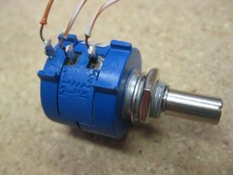
2 Return Kit Servos Servo Extensions Controller Analog USB/Tether Serial WiFi key (2) (2) Digital i/o Servo Power Adaptor AAA Battery Charger motors/ servos (4) Servo Mounting H/W (optional) Potentiometer battery Joystick Servo Horns USB A-A Cable (2) 2 (16) (2)
 Motors (2)")


")

3 Return Kit (cont.) Motors (2) Drive components 7.2V Battery charger (2) Motor Controller (4) Battery adapter Screw terminal sensor i/f cable (8) (2) 7.2V Battery Screw terminal motor i/f cable (4) (2) 3
4 Example Hookup 4

5 VEXnet Control System VEX Cortex microcontroller Dual ARM Cortex CPUs Programmable WiFi communications Gaming style controller Joysticks, buttons and accelerometers 5
6 VEXnet Cortex M3 Controller 8 Analog inputs 12 Digital inputs or outputs Speaker Output WiFi Proprietary Comm. Standard Serial Interfaces (UART, I2C) 10 Motor/Servo Ports System Status Indicators 6
 + Battery Power (for control")
7 VEX Cortex Pinouts Ground + 5V Signal/Control + Battery Power + Battery Power (for + control input) + Battery Power (for control input) 7

8 VEXnet Joystick 8 buttons on top 2 XY analog joysticks Power switch 6 AAA rechargeable batteries Plug-in USB/ WiFi Key 4 Button on front-side Programming Interface 2 Axis Accelerometer (X Tilt and Y Tilt) 8
9 System Features Wireless communication using g 2 2-wire proportional motor control outputs (not used by BEST) 8 3-wire PWM servo/motor outputs 12 discrete digital inputs/outputs + 1 speaker Wireless or direct USB port for program download Onboard power switch Built-in resettable fuse for overcurrent situations Powered by a single 7.2 volt RC hobby battery 9-volt backup battery for WiFi 9
10 DC Motors Use of internal motor controllers is not allowed (motor ports 1 and 10) External motor controller(s) connect via 3-wire external motor controller + 2-wire screw terminal cable use motor ports 2 thru 9 only 10
11 DC Motors (cont.) For power reasons, spread your motors so that you have no more than 2 motors plugged into ports 2-5 and no more than 2 motors plugged into ports 6-9. You risk over current and shutdown of the processor. Servo/motor ports are divided into 2 banks Bank1 = Ports 1-5 Bank2 = Ports 6-10 Each bank can support a maximum of 4 Amps of current BEST large motor stall current can reach 3.5 Amps. Sheet metal shield around the large motors IS needed and should not be removed. 11
 terminals Polarity is NOT marked on")

12 DC Motors (3) Solder wires to motor terminals or with the optional quick-disconnect (spade) terminals Polarity is NOT marked on motors: positive(+), negative(-) Wiring (and programming) will determine clockwise or counterclockwise rotation for positive stick movement 12
 3/32 hex wrench for mounting screws Small motor plate Large motor plate (cut down)")
13 DC Motors (4) Motors can be mounted with VEX Motor Mounting Kit provided in the consumables kit Large motor plate (bent up) 3/32 hex wrench for mounting screws Small motor plate Large motor plate (cut down) 13


14 3-Wire Motor Connection (1) Use a 4 wire tie here to secure the connection External Motor Controller Standard 2-wire motor cable Standard 3-wire PWM connector Screw terminals for attaching motor leads 14


15 3-Wire Motor Connection (2) Connectors are not keyed Connect red to red, black to black or reverse to change the motor response 15
 Connection to Cortex controller via 3-wire PWM +")
 Servo Servo Power Adaptors (2)")
16 Servos Futaba S3003 or S3004 series Maximum 120 degree rotation (+60, -60) Connection to Cortex controller via 3-wire PWM + Servo Power Adaptor use motor ports 2 thru 9 only Servo horns may be modified Servo Horns (2) Servo Servo Power Adaptors (2) (1) 16
17 Connecting a Servo Insert a Servo Power Adaptor cable into a motor port (2 through 9) Connect a servo (or servo extension cable) to the Servo Power Adaptor cable 17
 sensor screw terminal cable Connect to switch Connect to Cortex digital input")
18 Digital Input Connections Use for limit switches, microswitches Connect to Cortex digital inputs using 2-wire sensor screw terminal cables (white/black wires) sensor screw terminal cable Connect to switch Connect to Cortex digital input port 18
 Must program digital port for proper direction (input) Open = reads as 1 ; closed = reads as")
19 Digital Input Connections (cont.) Must program digital port for proper direction (input) Open = reads as 1 ; closed = reads as 0 sensor cable connector is keyed use digital ports 1 thru 12 19

20 Re-Syncing (Pairing) VEXnet If VEXnet does not connect, you may need to re-sync the joystick/controller pair by simply connecting a USB cable and powering on both units. 20
21 BEST Default Program Motor Limits Motor/Servo Port Joystick Channel Positive Direction Negative Direction Motor 2 (pair opposite of Motor 9) Stick 3 None None Motor 3 Stick 4 None None Motor 4 (pair opposite of Motor 7) Button 7 and 8 Up/Down/Left/Right None None Motor 5 Stick 1 Digital Input 1 Digital Input 2 Motor 6 Stick 2 Analog Input 1 Analog Input 1 Motor 7 (pair opposite of Motor 4) Button 7 and 8 Up/Down/Left/Right None None Motor 8 Button 6 Up None None Motor 9 (pair opposite of Motor 2) Stick 3 None None 21
22 BEST Programming Options Three different programming environments available MathWorks Simulink easycv4 RobotC Simulink is graphical programming/modeling environment with simulation capability (see what your program will do before you download it to the Cortex) easyc is a block programming environment (drag and drop programming elements) RobotC programs in C with a text editor, but it has runtime debugging (can step through program line by line and see what the results are) 22

23 Downloading a Program Direct USB Download Battery is not needed 23
24 Testing Tips Ensure your robot is safe to operate: Can t move or fall off table (use a jack-stand) All team members clear of moving parts Connect either WiFi keys or tether cable between the joystick and the Cortex controller. Make sure Cortex switch is in OFF position. Attach a charged battery. Turn on joystick (if not using tether). Turn Cortex switch to on position. For WiFi comm, link should establish in ~10 sec Test robot operations with transmitter. 24
25 LED Status Lights Joystick battery status Robot battery status Comm. link status Game status (not used by BEST) Green battery good charge Yellow battery - dying Red battery dead Green VEXnet comm. established Yellow VEXnet searching Lights on the controller and the joystick are the same 25
26 Questions 26
27 Team Tips Tin motor wires with solder before attaching to screw terminals since frayed stranded wires can cause a short or use the optional quick-disconnect (spade) terminals. Do NOT solder wires to Cortex connectors! Sensor cables, servo power adapter cables and external motor controllers are all keyed in correct orientation; insert and remove carefully to avoid destroying connectors. Tighten screws on motor and sensor connector cables so that wires are not loose and do not pull out. Mount Cortex to robot using #8 screws through holes provided; be careful not to over tighten. Avoid hot insertion of USB Keys. You may operate tethered by removing the USB WiFi key and connecting a USB A-A cable between joystick and Cortex. 27
28 Joystick Calibration If the motors hum or creep (sticks not returning to zero), the joystick may need to be recalibrated Calibration procedure (as extracted from the easyc help file) 1) The Joystick must be "Linked" to the Cortex Microcontroller using the VEXnet Keys. 2) Hold the "6U" Back Switch depressed. 3) While the "6U" Back Switch is depressed, use a small Allen Wrench (1/16" or smaller) or similar small straight tool to depress and hold the CONFIG Switch. 4) Hold both Switches depressed until you see the Joystick LED Flash RED and GREEN - you can now release both Switches. a. There is a 10 second time limit to complete the following steps 5 and 6. 5) Now move both Joystick Pots to the maximum position desired in all 4 directions - Up, Back, Left, and Right. a. If a movement is not detected in all 4 directions, a timeout will occur after about 10 seconds and the Cal Mode will be discontinued and the VEXnet LED will briefly Flash Red. b. The Joystick LED will continue to Flash RED and GREEN during the calibration process. 6) After movement is detected in all 4 directions, the Joystick LED will be ON and Solid GREEN. a. To "Save" the Calibration, depress and release the "8U" Top Switch Button. b. If the calibration is accepted and Saved, the Joystick LED will start Flashing Fast GREEN for a few seconds. c. If the Calibration is not Saved, a timeout will occur after about 10 seconds and the Cal Mode will be discontinued and the VEXnet LED will briefly Flash Red. d. To cancel a calibration, depress and release the "7U" Top Switch Button. The Cal Mode will be discontinued and the VEXnet LED will briefly Flash Red. e. If the Cal Mode is discontinued or saved, the Joystick LEDs will resume their normal function after the VEXnet LED briefly 28 Flashes.
29 Where to find help? Online resources/documentation (BRI Site) BEST Public Message Board (for anyone) Must register for login account Share ideas, resolve issues, Official Q&A Control System Category Use Official Q&A page during contest for rules specific questions Is this legal? 29
30 Where to find help? (cont.) VEX Forum Technical questions about VEX equipment easyc and RobotC dedicated forums included here Robotevents BEST Forum Dedicated user forum for BEST Robotics Must register for a login account 30
BEST Control System. Dave Wilkerson. September 12, 2015
 BEST Control System BEST Robotics, Inc. Dave Wilkerson September 12, 2015 Copyright 2012 BEST Robotics, Inc. All rights reserved. 1 Servos Joystick Return Kit AAA Battery Charger Analog WiFi key USB/Tether
Robot Design Workshop: VEX Hardware & Robot Building Basics
 Robot Design Workshop: VEX Hardware & Robot Building Basics Nik Kukert Bison BEST Robotics 1 Basics Only use parts supplied in the consumable and returnable kits (or approved optional items) Robots containing
BEST Generic Kit Notes GMKR00002 Revision 7; August 2011
 GMKR00002 Revision 7; August 2011 1.0 Introduction This document is for information only. Although it is consistent with the rules, please see the Generic Game Rules document for the official rules. All
BEST Generic Kit Usage Guide GMKR00002 Revision 9; August 2013
 GMKR00002 Revision 9; August 2013 1.0 Introduction This document is for information only. Although it is consistent with the rules, please see the Generic Game Rules document for the official rules. All
BEST Generic Kit Usage Guide GMKR00002 Revision 13; August 2017
 GMKR00002 Revision 13; 1.0 Introduction This document is for information only. Although it is consistent with the rules, please see the Generic Game Rules document for the official rules. All Returnable
VEX ARM Cortex -based Microcontroller and VEXnet Joystick User Guide
 1. VEX ARM Cortex -based Microcontroller and VEXnet Joystick Pairing Procedure: a. The Joystick must first be paired to the VEX ARM Cortex -based Microcontroller before they will work using VEXnet Keys.
BEST Generic Kit Notes GMKR00002 Revision 5; August 2010
 GMKR00002 Revision 5; 1.0 Introduction All Returnable Kit items, including boxes and packing, must be returned at the conclusion of the contest. This equipment will be used again next year; so do not modify
VEX Robot Remote Control Set-Up
 VEX Robot Remote Control Set-Up Note: Before proceeding with the VEXnet joystick setup on the following pages, complete these steps: 1) Open the RobotC program 2) Select File > Open Sample Program 3) Select
CORTEX Microcontroller and Joystick User Guide
 This is a User Guide for using the VEX CORTEX Microcontroller and VEX Joystick. Refer to the VEX Wiki (http://www.vexforum.com/wiki/index.php/vex_cortex_microcontroller) for updates to this document. 1.
Robotics Jumpstart Training II. EasyC: Software & Firmware Updates
 Robotics Jumpstart Training II EasyC: Software & Firmware Updates Objectives: Learn how to update EasyC Current Version: 4.2.1.9 Learn how to update Firmware VEX Joystick (Controller) VEX Microcontroller
CORTEX Microcontroller and Joystick Quick Start Guide
 This is a Quick Start Guide for using the VEX CORTEX and VEX Joystick. Refer to the VEX Wiki for updates to this document. 1. Basic connections; batteries, microcontroller, joysticks and VEXnet keys. a.
Brought to you by WIRED Les Quiocho September 30, 2017
 Brought to you by WIRED Les Quiocho September 30, 2017 Objectives To learn where to find necessary resources To recognize the basic electronic components of the BEST returnables kit To understand the software
Competitive VEX Robot Designer. Terminal Objective 1.3: operate the Tumbler using a jumper pin
 Skill Set 1: Driver/Operator Competitive VEX Robot Designer Terminal Objective 1.3: operate the Tumbler using a jumper pin Performance Objective: Using a Cortex microcontroller and EasyC V4, operate the
VEX Startup and Configuration Procedures
 VEX Startup and Configuration Procedures Power Up Open RobotC Step 2 Plug battery into the Cortex power port. The plug is keyed to only install one way. Black wire will face to the outside of the Cortex.
Cheap Control Systems. Cheap Twelve Channel (C12C) Servo Controller Version 1.0 OVERVIEW
 Servo Controller Version 1.0 OVERVIEW") Cheap Control Systems Cheap Twelve Channel (C12C) Servo Controller Version 1.0 The Cheap Twelve Channel (C12C) Servo Controller is a low cost embedded controller that allows a Sony Playstation 2 (PS2)
Cheap Control Systems Cheap Twelve Channel (C12C) Servo Controller Version 1.0 The Cheap Twelve Channel (C12C) Servo Controller is a low cost embedded controller that allows a Sony Playstation 2 (PS2)
Programming With easyc Kevin Barrett September 12, 2015
 BEST Robotic, Inc. easyc Team Training Programming With easyc Kevin Barrett September 12, 2015 1 What You ll Need Minimum System Requirements Windows XP/Vista/Win7, Mac not supported PIII-450MHz+, 256MB+
VEX Robotics - VEXnet Firmware Upgrade Utility Operating Instructions and Installation
 This document will guide you through the VEXnet Firmware Upgrade Utility Operating Instructions and Installation. The Tool is for updating firmware (Master Code) in the VEXnet 1.5 TX and RX Units and the
Step 1: Connect the Cortex to your PC
 This is a guide for configuring the VEX Cortex system to be programmed wirelessly using a VEXNet connection. These steps are required the first time you use your computer to program a specific VEX Cortex,
Innovation First, Inc Full-Size Robot Controller Reference Guide
 2004 Full-Size Robot Controller Reference Guide 2.19.2004 www.innovationfirst.com Page 2 Table of Contents 1. Robot Controller Overview... 3 2. Main Power Input... 4 3. Battery Backup Power... 4 4. PROGRAM...
Design Modular Planning
 Phys253 - Lecture 7, Part II Circuit Components & Layout Design Modular Planning Design by assembling simple circuit modules, such as filters or amplifiers Modules may be separated by buffers, where required
Cheap Control Systems. Cheap Six Channel (C6C) Servo Controller Version 2.3 OVERVIEW
 Servo Controller Version 2.3 OVERVIEW") Cheap Control Systems Cheap Six Channel (C6C) Servo Controller Version 2.3 The Cheap Six Channel (C6C) Servo Controller is a low cost embedded controller that allows the Sony Playstation 2 (PS2) game pad
Cheap Control Systems Cheap Six Channel (C6C) Servo Controller Version 2.3 The Cheap Six Channel (C6C) Servo Controller is a low cost embedded controller that allows the Sony Playstation 2 (PS2) game pad
Testing VEX Cortex Robots using VEXnet
 Testing VEX Cortex Robots using VEXnet This document is an inspection guide for VEX Cortex based robots. Use this document to test if a robot is competition ready. Method I. Using the ROBOTC Competition
This is an inspection failure, not meeting the requirement of >10k Ohm between either PD battery post and chassis.
 Troubleshooting This is a document put together by CSA Laura Rhodes that contains a lot of information about troubleshooting steps for a lot of common control system problems encountered at events. No
PS2 Wireless Owners Manual. By Robosoft Systems
 PS2 Wireless Owners Manual By Robosoft Systems Know your Board Symbol Device U1 P89V51RD2 Microcontroller U2 L298 Motor Driver 1 U3 L298 Motor Driver 2 U4 74HCT2400 Inverting buffer PS2 PS2 connector BATTRY
RobotC for VEX. By Willem Scholten Learning Access Institute
 RobotC for VEX By Willem Scholten Learning Access Institute 1 RobotCgetStarted.key - February 5, 2016 RobotC for VEX Section 1 - RobotC How to switch between VEX 2.0 Cortex and VEX IQ Section 2 - RobotC
2009 FRC Control System. Published by Team 103
 2009 FRC Control System Published by Team 103 Section 1 Overview of Components crio DSC (Digital Side Car) Power Distribution Board Wireless Gaming Adapter Wireless Router Driver Station Speed Controllers
GUIDE TO SP STARTER SHIELD (V3.0)
") OVERVIEW: The SP Starter shield provides a complete learning platform for beginners and newbies. The board is equipped with loads of sensors and components like relays, user button, LED, IR Remote and
OVERVIEW: The SP Starter shield provides a complete learning platform for beginners and newbies. The board is equipped with loads of sensors and components like relays, user button, LED, IR Remote and
FSXThrottle All Quadrants (all models) Notes*
 Notes*") FSXThrottle All Quadrants (all models) Notes* * Please note that not all features and options described or listed in these notes may apply to your model. Table of Contents Introduction:...3 Our Commitment:...3
FSXThrottle All Quadrants (all models) Notes* * Please note that not all features and options described or listed in these notes may apply to your model. Table of Contents Introduction:...3 Our Commitment:...3
527F CNC. Retrofit controller for machines made by Fadal Machining Centers. Installation and set-up manual Calmotion LLC
 527F CNC Retrofit controller for machines made by Fadal Machining Centers Installation and set-up manual 2008-2018 Calmotion LLC Calmotion LLC 7536 San Fernando Road Sun Valley, CA 91352 www.calmotion.com
Modern Robotics Inc. Sensor Documentation
 Sensor Documentation Version 1.0.1 September 9, 2016 Contents 1. Document Control... 3 2. Introduction... 4 3. Three-Wire Analog & Digital Sensors... 5 3.1. Program Control Button (45-2002)... 6 3.2. Optical
Number Name Description Notes Image 0101 Resistor, 100 ohm. brown-black-browngold. ¼ watt, 5% tolerance, red-red-brown-gold. brown-black-red-gold.
 Passive Components 0101 Resistor, 100 brown-black-browngold. 690620 0102 Resistor, 220 red-red-brown-gold. 690700 0103 Resistor, 1000 brown-black-red-gold. 690865 0104 Resistor, 10k 0201 Capacitor, 1 µf,
Plasma Retrofit Guide Upgrade Kit Installation Instructions
 Upgrade Kit Installation Instructions 1. TMC 3-in-1 Installation 1.1 Unplug the power cable from your CPR800 Control Unit and open the lid. Note The pictures show a NEMA 23 CRP800 Control Unit but the
Diagnostics of Genie / Sauer Danfoss Joystick Controllers Deutsch type connection
 Diagnostics of Genie / Sauer Danfoss Joystick Controllers Deutsch type connection Tools needed: Multi-meter Small Screwdriver Harness Adaptor 119613 Jumper Wires w/clips Three 1.5 volt AA or AAA Batteries
Troubleshooting ROBOTC with Cortex
 This guide is to designed to be used by a student or teacher as a reference for help troubleshooting ROBOTC software issues. Troubleshooting Topics Computer will not Recognize the VEX Cortex Not able to
Part 2: Building the Controller Board
 v3.01, June 2018 1 Part 2: Building the Controller Board Congratulations for making it this far! The controller board uses smaller components than the wing boards, which believe it or not, means that everything
HUB-ee BMD-S Arduino Proto Shield V1.0
 HUB-ee BMD-S Arduino Proto Shield V1.0 User guide and assembly instructions Document Version 1.0 Introduction 2 Schematic 3 Quick user guide 4 Assembly 5 1) DIP Switches 5 2) Micro-MaTch Connector Headers
logic table of contents: squarebot logic subsystem 7.1 parts & assembly concepts to understand 7 subsystems interfaces 7 logic subsystem inventory 7
 logic table of contents: squarebot logic subsystem 7.1 parts & assembly concepts to understand 7 subsystems interfaces 7 logic subsystem inventory 7 7 1 The Vex Micro Controller coordinates the flow of
Studuino Block Programming Environment Guide
 Studuino Block Programming Environment Guide [DC Motors and Servomotors] This is a tutorial for the Studuino Block programming environment. As the Studuino programming environment develops, these instructions
EZ-Bv4 Datasheet v0.7
 EZ-Bv4 Datasheet v0.7 Table of Contents Introduction... 2 Electrical Characteristics... 3 Regulated and Unregulated Power Pins... 4 Low Battery Warning... 4 Hardware Features Main CPU... 5 Fuse Protection...
Microsystems. SCI-6 Sound Card Interface Kit Version 1.09 January 2015
 UM Unified Microsystems SCI-6 Sound Card Interface Kit Version 1.09 January 2015 The SCI-6 interface was designed to be a low cost, high quality interface between your PC s sound card and radio transceiver.
TrimLine Vehicle Dock For: Dell Latitude 12 Rugged Tablet. User Guide
 TrimLine Vehicle Dock For: Dell Latitude 12 Rugged Tablet User Guide Description LATITUDE RUGGED 12 TABLET NPT DOCK LATITUDE RUGGED 12 TABLET DPT (dual RF pass thru) DOCK Part Number AS7.D920.100 AS7.D920.102
Parts List: Assembly Instructions:
 My Ride SERVICE MANUAl MyRide ASSEMBLY GUIDE 1.1 ASSEMBLY INSTRUCTIONS ASSEMBLING THE MYRIDE Parts List: Heavy Plate Stabilizer Fin - Right Stabilizer Fin - Left Stabilizer Fin - Large Middle Power Cord
Next Gen Platform: Team & Mentor Guide
 Next Gen Platform: Team & Mentor Guide 1 Introduction For the 2015-2016 season, the FIRST Tech Challenge (FTC) will be adopting a new controller for its robot competitions. The new platform, which will
Applications: Industrial Automation, Cranes, Hoists, Utility Vehicles, Off-highway, Ag, and Forestry Equipment
 TECHNICAL DATASHEET #TDA06020 CAN (SAE J1939) or (CANopen ) with Electronic Assistant P/N: A06020 Features: 1 or 2 axis inclination or slope sensors 2 axis (-80º 80º), functional up to +90 º 1 axis, vertically
Micro:bit - an Educational & Creative Tool for Kids
 Micro:bit - an Educational & Creative Tool for Kids SKU:DFR0497 INTRODUCTION micro:bit is a pocket-sized microcontroller designed for kids and beginners learning how to program, letting them easily bring
Dual 10A RC Relay MK2
 Dual 10A RC Relay MK2 Stockist:- Scale Warship 5 Beechwood Avenue New Milton Hants BH25 5NB 07855 941117 john@scalewarship.com 1 INTRODUCTION This unit allows the signal from a standard radio control receiver
AX1500. Dual Channel Digital Motor Controller. Quick Start Manual. v1.9b, June 1, 2007
 AX1500 Dual Channel Digital Motor Controller Quick Start Manual v1.9b, June 1, 2007 visit www.roboteq.com to download the latest revision of this manual Copyright 2003-2007 Roboteq, Inc. SECTION 1 Important
HP UPS R/T3000 G2. Overview. Precautions. Kit contents. Installation Instructions
 HP UPS R/T3000 G2 Installation Instructions Overview The HP UPS R/T3000 G2 features a 2U rack-mount with convertible tower design and offers power protection for loads up to a maximum of 3300 VA/3000 W
Variable Power Supply Digital Control Circuit Diagram Using Lm317
 Variable Power Supply Digital Control Circuit Diagram Using Lm317 DIGITAL POWER SUPPLY USING LM317 A Major Project Report Submitted partial fulfillment of the requirement for the award of the Degree of
Zero2Go. User Manual (revision 1.03) Wide Input Range Power Supply for Your Raspberry Pi. Copyright 2017 UUGear s.r.o. All rights reserved.
 Wide Input Range Power Supply for Your Raspberry Pi. Copyright 2017 UUGear s.r.o. All rights reserved.") Zero2Go Wide Input Range Power Supply for Your Raspberry Pi User Manual (revision 1.03) Copyright 2017 UUGear s.r.o. All rights reserved. Table of Content Product Overview... 1 Product Details... 3 Package
Zero2Go Wide Input Range Power Supply for Your Raspberry Pi User Manual (revision 1.03) Copyright 2017 UUGear s.r.o. All rights reserved. Table of Content Product Overview... 1 Product Details... 3 Package
* IMPORTANT * REGISTERING YOUR MACHINE
 * IMPORTANT * REGISTERING YOUR MACHINE Thank you for your purchase of the Keyline 994 Laser. Before continuing with machine setup and use, please complete the following; COMPLETE PRODUCT REGISTRATION FORM
Copyright White Box Robotics Inc. and Frontline Robotics Inc
 Disclaimer Working with electronics and installing the plastics will require care and patience. PROPER GROUNDING PROCEDURES before handling the electronics. Touching the robot chassis (which is common
Integrated Battery Control System LBCS Step-by-Step Setup Guide
 Integrated Battery Control System LBCS Step-by-Step Setup Guide 1. Components of the System 2. Components of the System 3. LBCS Overview 4. Battery Connections 5. Sense Board Installation 6. Sense Board
Abstract. GLV User Manual 1
 GLV User Manual 1 Abstract This user manual is a high level document that explains all operational procedures and techniques needed to operate the GLV system in a safe and effective manner. Anyone operating
Digital Camera Controller
 SHUTTERBUG PRO Digital Camera Controller ShutterBug Pro is a tiny accessory that helps take digital or film camera snapshots. It is ideal for photographers that need to remotely snap photos or to time
Installing 6 Indexer: PRS Standard Tools
 888-680-4466 ShopBotTools.com Installing 6 Indexer: PRS Standard Tools Copyright 2016 ShopBot Tools, Inc. page 1 Copyright 2016 ShopBot Tools, Inc. page 2 Table of Contents Overview...5 Installing the
PoE/FPR Kit for Auto-Sync Time Clock. The Auto-Sync Time Clock is a validated time system with a Web interface and auto discovery.
 ASTCPOEK PoE/FPR Kit for Auto-Sync Time Clock The Auto-Sync Time Clock is a validated time system with a Web interface and auto discovery. The ASTCPOEK Kit provides Power over Ethernet with Full Power
Blue Point Engineering
 DMX 8-Channel Driver Overview he DMX 8- Channel Driver board is designed to provide 8- consecutive channels of standard or extended range movements for analog type R/C s with output control pulses from
D115 The Fast Optimal Servo Amplifier For Brush, Brushless, Voice Coil Servo Motors
 D115 The Fast Optimal Servo Amplifier For Brush, Brushless, Voice Coil Servo Motors Ron Boe 5/15/2014 This user guide details the servo drives capabilities and physical interfaces. Users will be able to
Thursday, September 15, electronic components
 electronic components a desktop computer relatively complex inside: screen (CRT) disk drive backup battery power supply connectors for: keyboard printer n more! Thursday, September 15, 2011 integrated
EXPANSION HUB GUIDE. Expansion Hub Guide Rev 4 REV Robotics, LLC 2017
 fg EXPANSION HUB GUIDE Expansion Hub Guide Rev 4 REV Robotics, LLC 2017 TABLE OF CONTENTS 1 OVERVIEW... 1 1.1 Expansion Hub Basics... 1 1.2 Port Pin Outs... 2 1.3 Protection Features... 3 1.4 Cables and
Sten-SLATE ESP. Introduction and Assembly
 Sten-SLATE ESP Introduction and Assembly Stensat Group LLC, Copyright 2016 Legal Stuff Stensat Group LLC assumes no responsibility and/or liability for the use of the kit and documentation. There is a
THIS IS THE CURRENT FF USER GUIDE AS OF PLEASE DO NOT USE ANY PREVIOUSLY DATED VERSIONS
 THIS IS THE CURRENT FF USER GUIDE AS OF 02-26-2012 PLEASE DO NOT USE ANY PREVIOUSLY DATED VERSIONS INTRODUCTION: I compiled this guide from information posted on RCGroups.COM and from GoodLuckBuy.COM where
THIS IS THE CURRENT FF USER GUIDE AS OF PLEASE DO NOT USE ANY PREVIOUSLY DATED VERSIONS
 THIS IS THE CURRENT FF USER GUIDE AS OF 05-04-2012 PLEASE DO NOT USE ANY PREVIOUSLY DATED VERSIONS INTRODUCTION: I compiled this guide from information posted on RCGroups.COM and from GoodLuckBuy.COM where
ARDUINO MEGA ADK REV3 Code: A000069
 ARDUINO MEGA ADK REV3 Code: A000069 OVERVIEW The Arduino MEGA ADK is a microcontroller board based on the ATmega2560. It has a USB host interface to connect with Android based phones, based on the MAX3421e
Q2 XBee Handheld Controller Assembly Guide
 Q2 XBee Handheld Controller Assembly Guide Copyright Quantum Robotics Inc. Q2 Controller V1.0 1 Parts List: The kit comes with 14 individual bags. 1. Case Top and Bottom 2. Case Screw Package containing:
Victor BB Comprehensive Guide Preliminary. Revision 1.3
 Preliminary Revision 1.3 Table of Contents 1. Purpose of this Guide... 3 2. Installing the Victor Dashboard... 5 2.1. Installing Serial Drivers... 7 2.1.1. Installing Serial Drivers Prolific PL2303...
Applications: Industrial Automation, Cranes, Hoists, Utility Vehicles, Off-highway, Ag, and Forestry Equipment
 Features: 1 or 2 axis inclination or slope sensors 2 axis (-80º 80º), functional up to +90 º 1 axis, vertically positioned (-180º 180º or 0 360º) High resolution and accuracy SAE J1939 (CANopen models
Web Site: Forums: forums.parallax.com Sales: Technical:
 Web Site: www.parallax.com Forums: forums.parallax.com Sales: sales@parallax.com Technical: support@parallax.com Office: (916) 624-8333 Fax: (916) 624-8003 Sales: (888) 512-1024 Tech Support: (888) 997-8267
Nov. 07, 2013 p. 5 - changed the B axis unit value to from Changed by Randy per Frank s request.
 Correction notes Nov. 07, 2013 p. 5 - changed the B axis unit value to 45.1389 from 40.0000. Changed by Randy per Frank s request. Jan. 22, 2018 p. 5 - changed the B axis unit value and corresponding picture
Activity Inputs and Outputs VEX
 Activity 3.1.1 Inputs and Outputs VEX Introduction Robots are similar to humans if you consider that both use inputs and outputs to sense and react to the world. Most humans use five senses to perceive
The Control System. Student Interface Batteries Contest Plan Calibration Presentation. The Control Box
 Wiring Your Machine The Control System The Control Box Student Interface Batteries Contest Plan Calibration Presentation System Overview The picture below is a schematic overview of the whole system. Two
INTRODUCTION TABLE OF CONTENTS 1 INTRODUCTION WELCOME TO THE 2009 FRC CONTROL SYSTEM Suggestions for Getting Started 2
 Section 1 INTRODUCTION TABLE OF CONTENTS 1 INTRODUCTION 2 1.1 WELCOME TO THE 2009 FRC CONTROL SYSTEM 2 1.1.1 Suggestions for Getting Started 2 1.2 TECHNICAL SUPPORT FOR THE 2009 FRC CONTROL SYSTEM 2 1.3
E102 - Advanced Strain Gauge Transducer Display Interface. Contents
 E102 - Advanced Strain Gauge Transducer Display Interface Contents Torque Transducer Display Interface: TSE3249R Strain Gauge Transducer Display Interface [E102] Operating Guide: TSE2098V (Includes Introduction,
SPIRIT. Phase 5 Analog Board Computer and Electronics Engineering
 SPIRIT Phase 5 Analog Board Computer and Electronics Engineering In this exercise you will assemble the analog controller board and interface it to your TekBot. Print out the schematic, silkscreen and
21 TRACK MAINTENANCE GUIDE
 Mountain Engineering II, Inc. 21 TRACK MAINTENANCE GUIDE 1233 Sherman Drive, Longmont, CO 80501-6133 303-651-0277 303-651-6371 (fax) www.mountainengineering.com Table of contents Table of contents...2
E3 CNC Router Troubleshooting Guide
 Simple Cost Effective Designs. E3 CNC Router Troubleshooting Guide The purpose of this document is to give those new to CNC routing is a quick reference for the common issues of getting the E3 CNC router
Blue Point Engineering
 DMX Controllers Controllers C DMX - 8Ch Relay Modules ( BPE # DMX-3001 )- Mechanical ( BPE # DMX-3003) - SS Relay 8 Solid State relay outputs Solid State Relays AC/DC DMX - 8Ch SS Relay Modules ( BPE #
E3 CNC Router Troubleshooting Guide
 Simple Cost Effective Designs. E3 CNC Router Troubleshooting Guide The purpose of this document is to give those new to CNC routing is a quick reference for the common issues of getting the E3 CNC router
LED Maintenance Instructions
 Chapter 5 LED Maintenance Instructions This guide describes the maintenance procedures for the LED portion of your DayStar or TekStar sign. 1.800.237.3928 stewartsigns.com Rev1802 Intentionally Left Blank
DOWNLOADING THE APP FOR APPLE PHONES: DOWNLOADING THE APP FOR ANDROID PHONES: For Android Phones go to Google Play or the Android Store.
 DOWNLOADING THE APP FOR APPLE PHONES: DOWNLOADING THE APP FOR ANDROID PHONES: For Android Phones go to Google Play or the Android Store. For Apple Phones go to the app store and click GET. Make sure your
Lightning Stitch Assembly
 ABM International, Inc. 1 1.0: Parts List Lightning stitch motor and drive assembly (Qty. 1) Lightning stitch piggy backed controller board assembly (Qty. 1) Touchscreen (Qty. 1) 2 9-pin Serial cable (Qty.
Cannes Edition Product List
 Cannes Edition Product List Congratulations on your purchase of a DSLRProsCannes Edition Aerial Kit. Inside your Special Edition tough case you will find the following items with numbers that correspond
MAGIXBOX TM. Quick Start Guide
 TM TM by TouchMagix MAGIXBOX TM Quick Start Guide What s in the box: Ankle Ceiling Plate Extendable Rod Connector Piece Middle Piece Universal Spider Super clamp with ball socket Safety Cable Projector
ZYX User Manual V Revision
 ZYX User Manual V.00 206.07.26 Revision Contents Warning and Disclaimer... 3 I. Product Introduction... 4 II. Product List... 5. Package Contents... 5 III. Mounting & Configuration... 6. Gimbal Controller
Standard Options. Model 4100 Position Indicating Meter. Three Phase Motor Control. Positran Transmitter
 Standard Options Model 4100 Position Indicating Meter A percent-of-full-travel meter is supplied with a trim potentiometer resistor, terminal block and connectors. A potentiometer is required in the actuator
Chapter 2: Introducing the mbed tw rev
 Chapter 2: Introducing the mbed tw rev. 26.8.16 If you use or reference these slides or the associated textbook, please cite the original authors work as follows: Toulson, R. & Wilmshurst, T. (2016). Fast
Homework 13: User Manual
 Homework 13: User Manual Team Code Name: Infrarat Group No. 14 User Manual Outline: Brief (marketing-style) product description Product illustration annotated with callouts for each control/display Product
Power Supply, Arduino MEGA 2560, and Stepper Motors Connections
 Power Supply, Arduino MEGA 2560, and Stepper Motors Connections By: Maram Sulimani Abstract: Arduino MEGA 2560 is required for this project to control the movement of the 3D printer axis and its extruder.
STEP 1: MODULE MOUNTING / WIRING:
 VER1.0 PINOUT DIAGRAM: PORT 1 - INPUT 1 (S.BUS, PWM, PPM INPUT) PORT 2 - INPUT 2 (PWM MODE INPUT OR AUX OUTPUT DEFINED IN SOFTWARE) PORT 3 - OUTPUT 1 (S.BUS OUTPUT) PORT 4 - OUTPUT 2 (SERVO OUTPUT) PORT
HUB-ee BMD-S Arduino Proto Shield V1.1
 HUB-ee BMD-S Arduino Proto Shield V1.1 User guide and assembly instructions Document Version 0.5 Introduction & Board Guide 2 Schematic 3 Quick User Guide 4 Assembly Guide 6 Kit Contents 7 1) Diodes and
KTX PC User Manual. KumoTeck 06/25/2010. Tech Support. Masahiro Ishida
 KTX PC User Manual KumoTeck 06/25/2010 Tech Support Masahiro Ishida 1 Introduction Thank you for purchasing KTX-PC from us. This Manual explains how we treat this robot and its accessories. Please read
MegaPi Born to Motion Control
 MegaPi Born to Motion Control SKU: 10050 Weight: 130.00 Gram 1. Overview MegaPi is a main control board specially designed for makers and also an ideal option for being applied to education field and all
Arduino Uno. Arduino Uno R3 Front. Arduino Uno R2 Front
 Arduino Uno Arduino Uno R3 Front Arduino Uno R2 Front Arduino Uno SMD Arduino Uno R3 Back Arduino Uno Front Arduino Uno Back Overview The Arduino Uno is a microcontroller board based on the ATmega328 (datasheet).
ARDUINO M0 PRO Code: A000111
 ARDUINO M0 PRO Code: A000111 The Arduino M0 Pro is an Arduino M0 with a step by step debugger With the new Arduino M0 Pro board, the more creative individual will have the potential to create one s most
How-To #3: Make and Use a Motor Controller Shield
 How-To #3: Make and Use a Motor Controller Shield The Arduino single-board computer can be used to control servos and motors. But sometimes more current is required than the Arduino can provide, either
ABM International, Inc. Lightning Stitch Checklist 9/13/2013
 ABM International, Inc. Lightning Stitch Checklist 9/13/2013 1) Piggy backed board assembly (1) Piggy back board assembly tested? Yes No 24v passed XB passed XA passed YB passed YA passed SAFE passed S/S
VEX/RobotC Video Trainer Assignments
 VEX/RobotC Video Trainer Assignments Mr. Holmes Mechatronics I To view the VEX videos assigned for homework, click on the following link to access the Vex Video Trainer: http://www.education.rec.ri.cmu.edu/products/teaching_robotc_cortex/
Connecting Your Rudder Potentiometers to The BU0836 Controller Card.
 Connecting Your Rudder Potentiometers to The BU0836 Controller Card. There are 3 Potentiometers fitted to the rudder pedals. Left Brake, Right Brake and the Rudder itself. This is how to connect them to