For normal duty, design the VFD voltage level at 480 Volt, 3 Phase, 60 Hertz. (In Canada, 600 Volt, 3 Phase, 60 Hertz.)
|
|
|
- Allison Palmer
- 6 years ago
- Views:
Transcription
1 Introduction The Variable Frequency Drive Design Guidelines provides design criteria and specifications used in the procurement and application of variable frequency drives (VFDs). Table of Contents 1. Introduction 2. Design 3. Installation 4. Documentation and Deliverables 5. Products or Material 6. Safety 7. Calibrations and Testing 8. Identification 9. Summaries 1. Introduction Consider all standards described in this document mandatory unless otherwise identified as optional or preferred. Any variance from GMI requirements or preferences requires prior GMI Engineering approval. Obtain approval from the engineer that issued this document or has been designated as responsible for project deliverables. GMI will provide and document specific project requirements and approvals. 2. Design Use the following general design guidelines. For normal duty, design for operating frequencies between 30Hz and 90Hz. Verify and validate that the reducer/reduction gear sizes complies with the designed operating frequencies. For normal duty, design the VFD voltage level at 480 Volt, 3 Phase, 60 Hertz. (In Canada, 600 Volt, 3 Phase, 60 Hertz.) Use only UL listed VFDs (CSA in Canada). Install VFDs inside a control cabinet, and rate them for IP20, NEMA Type 1 panel mounting. CIS_302_Variable_Frequency_Design_Guidelines_WHQ.doc, 0, October
2 Design Match the drive size to the motor size for normal duty, with the minimum VFD sized for a 1 HP motor. For heavy or severe duty, size the drive to one size larger than the motor to allow for constant torque and higher overload protection. If possible, use similar sized drives throughout a system. GMI discourages the use of DC motors. GMI discourages the uses of mechanical variable speed drives. Refer to 301_Electric_Motor_Design_Guidelines. 2.1 Communications and Controls Make sure the VFD is capable of the following communication protocols. The controls engineer determines the protocol choice based on the infrastructure at the VFD s location. Make sure that communications to and from the drive include all start and stop commands, speed control and setpoints, and diagnostics. ControlNet Limit the number of nodes to 20 for each segment. Use Quad Shield coax (Belden 3092A) cable for ControlNet applications. DeviceNet Limit the number of nodes to 35. Refer to the manufacturer s recommendations to determine the proper configuration. EtherNet IP Limit the number of nodes to 20 for each segment. Use the manufacturer s EtherNet/IP Performance and Application Guidelines. AB-RIO use for legacy systems only Plan for integration of VFD controls with the human machine interface (HMI) including operations status displays on the HMI, fault handling routines, and trouble shooting features. GMI will provide HMI templates with diagnostics, alarms, and status indications during process design. Fit each VFD with a full-featured keypad if one is offered as an option. CIS_302_Variable_Frequency_Design_Guidelines_WHQ.doc, 0, October
3 Installation 3. Installation Follow all manufacturer recommendations and requirements for mounting and installing VFDs. Additional requirements include: Always mount the VFD in an enclosure. Do not install more than three motor power feeds sharing the same conduit. Ground the VFDs according to manufacturer recommendations. Use shielded cable (Belden 295XX where XX is related to wire gauge) from the VFD to the load. Keep cable lengths shorter than 100-feet. If the application includes a distance greater than 100-feet, follow the manufacturer s recommendations. GMI does not require RFI Filters. Supply VFDs with an Allen-Bradley 140M Self-Protecting Motor Starter (per manufacturer s recommendations and sizing tables) or Bussmann Optima (OPM- 1038RSWC) fused primary protection (short circuit protection). GMI prefers the Allen-Bradley 140M Self-Protecting Motor Starters. (See drawings in Safety on page 6 for typical installation.) Do NOT use a contactor on the line side of the VFD. Use load-side contactors for safety (if the A-B safe-off option is not available). Refer to the VFD manufacturer s documentation for additional safety recommendations. (See drawings in Safety on page 6 for typical installation.) Install a local motor disconnect switch on all motors. Make each local motor disconnect switch lockable and suitable as a safety device in compliance with GMI s lockout tagout (LOTO) program. Furnish the local disconnect with an auxiliary contact wired to a PLC input. The preferred disconnect switch is either a Hubbell HBLDS#AC (where # is 3 [30A], 6 [60A], or 10 [100A]) or an Allen- Bradley 194E-CAxxE-P11 (where xx is related to the load size). CIS_302_Variable_Frequency_Design_Guidelines_WHQ.doc, 0, October
4 Documentation and Deliverables 4. Documentation and Deliverables Refer to GMI s drawing templates for preferred documentation format and expected content. GMI will provide HMI templates with diagnostics, alarms, and status indications during process design. For each VFD furnished with a system, include the final configured parameters, as changed from the default, within the installation wiring drawings. These parameters will be used to re-configure a VFD when required. The following table is an example of parameter table with changes from default (not all inclusive). Parameter # Name Value Default Units 41 MOTOR NP VOLTS VAC 42 MOTOR NP FLA 8 8 AMPS 44 MOTOR NP RPM RPM 45 MOTOR NP POWER MOTOR OL HERTZ 0 0 HZ 54 MAXIMUM VOLTAGE VAC 140 ACCEL TIME SEC 142 DECEL TIME SEC 148 CURRENT LMT VAL AMPS 158 DC BRAKE LEVEL 0 0 AMPS 201 LANGUAGE ENGLISH NOT SELECTED 276 LOGIC MASK DIGITAL IN1 SEL NOT USED STOP-CF 362 DIGITAL IN2 SEL NOT USED START 363 DIGITAL IN3 SEL ENABLE AUTO/MAN 364 DIGITAL IN4 SEL NOT USED SPEED SEL DIGITAL IN5 SEL NOT USED SPEED SEL DIGITAL IN6 SEL NOT USED SPEED SEL 3 CIS_302_Variable_Frequency_Design_Guidelines_WHQ.doc, 0, October
5 Products or Material 5. Products or Material Use the following Allen-Bradley PowerFlex Drives. Drive Control Configuration Horsepower Range Notes PowerFlex 4 PowerFlex 40 PowerFlex 70 PowerFlex 700 Non-network solutions only EtherNet/IP DeviceNet ControlNet EtherNet/IP DeviceNet ControlNet EtherNet/IP DeviceNet ControlNet 1 5 Hp 1 15 Hp An additional load side contactor is required for safety 1 50 Hp GMI preferred (safe-off option) Hp Typical on Mixer applications (I/O vector options C or D) CIS_302_Variable_Frequency_Design_Guidelines_WHQ.doc, 0, October
6 Safety 6. Safety Refer to GMI templates and typical examples of the safety circuits to meet the requirements of a NFPA Category 0 Stop (immediate removal of power to the motor) or Category 1 stop (controlled stop, then removal of power to the motor). In addition, design E-stops to meet the requirements of EN 954-1:1997; Risk Category 3. Remove power by electromechanical components (NFPA-79). The PowerFlex Safe-Off board, when used with suitable safety components, provides protection according to EN 954-1:1997; Risk Category 3 for safe off and protection against restart. The PowerFlex safe off option is just one safety control system. All components in the system must be chosen and applied correctly, to achieve the desired level of operator safeguarding. Make sure that resetting of any safety circuit device does not initiate any hazardous conditions. Avoid automatic equipment restart when an e-stop button is pulled out or a safety gate is closed. Refer to the VFD manufacturer s documentation for additional safety considerations. The drawings on the following pages provide an example of a typical safety circuit installation. CIS_302_Variable_Frequency_Design_Guidelines_WHQ.doc, 0, October
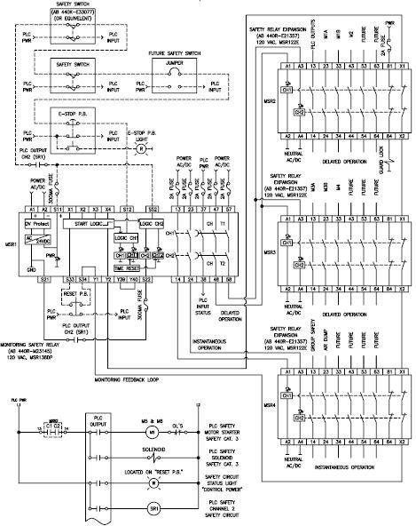
7 Safety CIS_302_Variable_Frequency_Design_Guidelines_WHQ.doc, 0, October
8 Calibrations and Testing 7. Calibrations and Testing Demonstrate full range of speed (such as 30 90Hz) to validate proper reducer sizing. 8. Identification Label all motors at a permanent location near, but not on, the motor or gear reducer. Make sure the label contains motor tag number (refer to the equipment tagging guidelines), the common name (such as PRODUCT PUMP 3), and starter location. Label cabinets or enclosures that house contactors, starters, or other control devices on the outside with the source of the electrical power used. This might be the number of a specific MCC or a breaker number from a lighting distribution panel or general utility power panel. Label all major components (such as VFD, motor starters or local disconnects) as identified on the schematic diagrams. Identify all wires at each termination. Use wire markers to identify a unique number that corresponds to the schematic diagram. When the wires are part of a PLC system, label them with the same number as the input or output points of the PLC. CIS_302_Variable_Frequency_Design_Guidelines_WHQ.doc, 0, October
9 Summaries 9. Summaries Enter information in these tables to track revisions to the master document. NOTE: In the Entry column, enter your information between the dashes. The entries automatically update matching document properties. Document Property Entry Master Owner Master Number -0- -Daniel Migliori- Increment revision numbers by one. Master Date -5/11/05- Number Date Owner Summary (Brief description of major changes) 0 5/11/2005 Daniel Migliori Original development CIS_302_Variable_Frequency_Design_Guidelines_WHQ.doc, 0, October
10 Summaries 9.1 Plant Customization Tracking Enter information in these tables to track revisions to plant customized documents. NOTE: In the Entry column, enter your information between the dashes. The entries automatically update document properties. Document Property Entry Plant Code -XXX- Plant Owner -Enter Name- Plant Number Plant Date -3/29/05- Use the following format for the Plant Number: <Master Number>.<Plant Number> Number Date Owner Summary (Brief description of major changes) 0 CIS_302_Variable_Frequency_Design_Guidelines_WHQ.doc, 0, October
Variable Frequency Drive Design Guidelines
 Variable Frequency Drive Design Guidelines The Variable Frequency Drive Design Standard provides design criteria and specifications used in the procurement and application of variable frequency drives
1. Introduction. 2. Design. Safety and Emergency Stop Circuit Design Standard. Safety and Emergency Stop Circuit Design Standard.
 Safety and Emergency Stop Circuit Design Standard The Safety and Emergency Stop Circuit Design Standard provide design criteria and specifications for safety and emergency stop circuits used in General
1. Summary. 2. Contacts. Safety Controls Guidelines. Table of Contents
 The provide design criteria and specifications for safety circuit in compliance with ISO 13849-1 PL d Safety of machinery, used in General Mills manufacturing facilities. Table of Contents 1. Summary 2.
PowerFlex 400 AC Drive Guide Specification
 PowerFlex 400 AC Drive Guide Specification Adjustable Frequency Drives with Bypass 3.0 50HP @ 208V AC 3.0 350HP @ 480V AC PART 1 GENERAL 1.01 Quality Assurance A. The manufacturer shall have minimum 5
BuildingName The Description of the Project P DOCUMENTS
 ARCHITECTURE, ENGINEERING AND CONSTRUCTION P00000000 0000 DOCUMENTS ARCHITECTURE & ENGINEERING 326 East Hoover, Mail Stop B Ann Arbor, MI 48109-1002 Phone: 734-764-3414 Fax: 734-936-3334 SPECIFICATION
SECTION VARIABLE FREQUENCY MOTOR CONTROLLERS (VFD)
") SECTION 26 29 23 VARIABLE FREQUENCY MOTOR CONTROLLERS (VFD) PART 1 -GENERAL 1.1 SYSTEM DESCRIPTION A. Definitions: The Variable Speed AC Motor Drive (hereafter referred to as "VFD") shall be designed to
SECTION 26 29 23 VARIABLE FREQUENCY MOTOR CONTROLLERS (VFD) PART 1 -GENERAL 1.1 SYSTEM DESCRIPTION A. Definitions: The Variable Speed AC Motor Drive (hereafter referred to as "VFD") shall be designed to
SECTION SOLID-STATE REDUCED VOLTAGE STARTERS
 SECTION 26 29 13.16 PART 1 - GENERAL 1.1 THE REQUIREMENT A. General: The CONTRACTOR shall provide solid-state reduced voltage motor starters, complete and operable, in accordance with the Contract Documents.
SECTION VARIABLE FREQUENCY DRIVES
 PART 1 GENERAL 1.01 DESCRIPTION This specification section establishes the requirements for variable frequency motor drives. The associated motor(s) shall be specified separate from the drive and listed
Bulletin 290/291, 294 ArmorStart LT Distributed Motor Controllers Description/Features
 Bulletin 290/291, 294 /Features Product Line ArmorStart LT, Bulletin 290/291/294 is an integrated, pre-engineered distributed motor control solution. It provides excellent performance at a great value
ENGINEERED SOLUTIONS. Solutions for Any Application. us.mitsubishielectric.com/fa/en/
 ENGINEERED SOLUTIONS Solutions for Any Application us.mitsubishielectric.com/fa/en/ Engineered Solutions for Any Application Manufactured to the highest standards in UL approved facilities, the Engineered
SSW06. Soft Starters.
 The is WEG s third generation Soft Starter line. The keypad, with dual display, has red LED digits which provide visibility and make programming easier. Integral bypass contacts eliminate heat dissipation
 90F Guy L Warden & Sons Thrush Model 720 4 X 2.5 Flow Guide 90F Guy L Warden & Sons 90F PART 1 GENERAL OVERVIEW Product Scope: SECTION 15 iqpump ENGINEERING SPECIFICATIONS VARIABLE FREQUENCY DRIVES The
ABB Industrial Systems Inc. Standard Drives. ACH500-06E Effective 6/1/95
 Part 1 - GENERAL ASEA BROWN BOVERI ABB Industrial Systems Inc. Standard Drives ACH500-06E Effective 6/1/95 Sample Specification for Adjustable Frequency Drives (2 to 400 HP) for Variable Torque Applications
IPS INTELLIGENT PUMP STARTER
 IPS INTELLIGENT PUMP STARTER The IPS Intelligent Pump Starter features SMARTSTART motor protection, integrated electronic pump protection overload, and power metering and data logging options. Ø & Ø, 0/60
1510 MOTOR CONTROLLERS
 SECTION 262913- MOTOR CONTROLLERS PART 1 - GENERAL 1.1 RELATED DOCUMENTS A. Drawings and general provisions of contract, including general and supplementary conditions and Division 1 specification section,
4/8/ nd Annual OTCO WW Workshop W/WW Product Overview ACQ550. ABB Slide 1
 4/8/2015 52 nd Annual OTCO WW Workshop W/WW Product Overview ACQ550 Slide 1 Drive Basics Why Use Adjustable Speed Drives? Reduced Energy Consumption Improved Process Control / Efficiency Increased Product
JK Series POWER DISTRIBUTION. Solid State Starters Medium Voltage A
 POWER DISTRIBUTION JK Series Solid State Starters Medium Voltage 200-400-600-720A SOLID STATE STARTER JKSSS4+ Series The JKSSS Series of motor starter is the result of extensive research and development.
GV3000/SE 230 VAC 1-20 HP General Purpose (Volts/Hertz) and Vector Duty Drive Software Start-Up and Reference Manual Version 6.04
 and Vector Duty Drive Software Start-Up and Reference Manual Version 6.04") GV3000/SE 230 VAC 1-20 HP General Purpose (Volts/Hertz) and Vector Duty Drive Software Start-Up and Reference Manual Version 6.04 Instruction Manual D2-3387-4 The information in this manual is subject
GV3000/SE 230 VAC 1-20 HP General Purpose (Volts/Hertz) and Vector Duty Drive Software Start-Up and Reference Manual Version 6.04 Instruction Manual D2-3387-4 The information in this manual is subject
Pump Data Sheet - Patterson HVAC Pumps Company: Intermountain Hydron Name: Cache County Mountain Crest Date: 09/24/2018
 Pump Data Sheet - Patterson HVAC Pumps Company: Intermountain Hydron Name: Cache County Mountain Crest Date: 09/24/2018 Tags: P-8 1800RPM Premium Efficient Motor 460/3/60 Pump and Motor Weight: 183lbs
SMARTSTART MOTOR STARTERS
 SMARTSTART MOTOR STARTERS MCG WWW.MCG-USA.COM 1 AT A GLANCE Covers all line voltages from 200-600V AC, single or three phase Transformer supplies a 24V AC coil voltage, no matter the line voltage 12V AC/DC
PowerFlex 750-Series AC Drives
 PowerFlex -Series AC Drives Cost-effective Solution Designed for Ease of Use, Integration & Application Flexibility. The Allen-Bradley PowerFlex -Series of AC Drives is aimed at maximizing your investment
Intelligent Motor Control Solutions Process Solutions Summit
 Intelligent Motor Control Solutions Process Solutions Summit Roger Dorsel Power Control Area Manager 5058-CO900F 2 3 Motor Control Technologies Scalable Low Voltage & Medium Voltage Solutions Across-the-Line
Smartstart Control Module
 Smartstart TECHNOLOGY What is Smartstart? The patented Smartstart control module is an integrated, seamless solution that incorporates operator control, superior motor protection, and automation system
SmartWire-DT In panel and on machine wiring solutions. Revolutionizing in-panel control wiring and on-machine connection of sensors and actuators
 SmartWire-DT In panel and on machine wiring solutions Revolutionizing in-panel control wiring and on-machine connection of sensors and actuators SmartWire-DT Changing the way panels... Reduce cost throughout
GV3000/SE Operator Interface Module (OIM) User Guide Version 2.0 M/N 2RK3000
 User Guide Version 2.0 M/N 2RK3000") GV3000/SE Operator Interface Module (OIM) User Guide Version 2.0 M/N 2RK3000 Instruction Manual D2-3342-2 The information in this manual is subject to change without notice. Throughout this manual, the
GV3000/SE Operator Interface Module (OIM) User Guide Version 2.0 M/N 2RK3000 Instruction Manual D2-3342-2 The information in this manual is subject to change without notice. Throughout this manual, the
PowerFlex 40 Sample Specification
 PowerFlex 40 Sample Specification GENERAL REFERENCES REGULATORY REQUIREMENTS Designed to meet the following specifications: NFPA 70 - US National Electrical Code NEMA ICS 3.1 - Safety standards for Construction
DriveGuard. Safe-Off Option for PowerFlex 70 AC Drives. User Manual.
 DriveGuard Safe-Off Option for PowerFlex 70 AC Drives User Manual www.abpowerflex.com Important User Information Solid state equipment has operational characteristics differing from those of electromechanical
Product Overview. PowerFlex 520-Series AC Drives Feature. Modular Design. Packaging and Mounting. Optimized Performance
 Product Overview The PowerFlex 520-Series AC drive delivers an innovative design that is remarkably versatile and can accommodate systems ranging from standalone machines to simple system integration.
PanelView Plus/VersaView CE Terminals and Display Modules
 Installation Instructions PanelView Plus/VersaView CE Terminals and Display Modules (Catalog Numbers 2711P-xxxxxx, 6182H-xxxxxx) English Inside: Overview...2 For More Information...2 Modular Components...3
SED2 VFD NEMA Type 3R Bypass/Air Conditioner
 SED2 VFD NEMA Type 3R Bypass/Air Conditioner Description The NEMA Type 3R Bypass with Air Conditioner allows SED2 to be employed in a harsh environment. The SED2 is designed specifically for HVAC applications
PRODUCT PROFILE. PowerFlex 700 AC Drive. Powerful Performance. Flexible Control. Excellent Performance
 PRODUCT PROFILE PowerFlex 700 AC Drive Powerful Performance. Flexible Control. Whether your application requires simple speed control, demanding torque control, or a variety of horse power ratings, the
SSW06. Soft Starters. Applications. Standard Features. Pumps Fans Blowers Compressors Crushers Saws Grinders Mixers.
 General Information CFW10 CFW100 CFW08 CFW500 CFW700 CFW701 CFW11 EDP11 CFW11M SSW05 SSW07 GPH2 TPH2 The is WEG s third generation Soft Starter line. The keypad, with dual display, has red LED digits which
Helm-Pak Survey. SPM: Tonnage: English Metric Type: OBI/Gap Straight Side Single Action Double Action
 Company Phone: Address: Fax: City: Contact: State: Zip: Email: Rep.: Company: Press Data: Manufacturer: Model: Serial Number: Year of Manufacture: SPM: Tonnage: English Metric Type: OBI/Gap Straight Side
1336 PLUS II Quick Start Guide
 1336 PLUS II Quick Start Guide This Quick Start Guide summarizes the basic steps needed to install, start-up and program the 1336 PLUS II Adjustable Frequency AC Drive. The information provided Does Not
Lowering Lifecycle Costs
 Lowering Lifecycle Costs with Intelligent Motor Control Centers Standards Certification Education & Training Publishing Conferences & Exhibits Speakers: Presented and Authored by Jeff M. Miller, PE, ENV
OVERLOAD RELAYS POWER & ACTUATION PROVEN. series
 POWER & ACTUATION OVERLOAD RELAYS series Need reliable, accurate overload and phase-loss protection for your motors? c3controls Series Bimetallic Overload Relays provide unmatched protection and can be
E1 Plus Electronic Overload Relay
 ROCKWELL AUTOMATION PROCUREMENT SPECIFICATION PROCUREMENT SPECIFICATION E1 Plus NOTICE: The specification guidelines in this document are intended to aid in the specification of products. Specific installations
WELKER VFD PANEL BOXES
 ISO 9001 REGISTERED WELKER VFD PANEL BOXES NOTE: CUSTOMER SUPPLIED VFD MUST HAVE A MINIMUM OF FOUR (4) INPUTS. FOR PROPER FUNCTION, BOTH DECELERATION SWITCHES AND BOTH IN-POSITION SWITCHES MUST BE WIRED
GV3000/SE General Purpose (Volts/Hertz) and Vector Duty AC Drive, HP, 230V AC
 and Vector Duty AC Drive, HP, 230V AC") Software Start-Up and Reference Manual D2-3416-2 GV3000/SE General Purpose (Volts/Hertz) and Vector Duty AC Drive, 30-100 HP, 230V AC Version 6.04 Important User Information Solid-state equipment has operational
Software Start-Up and Reference Manual D2-3416-2 GV3000/SE General Purpose (Volts/Hertz) and Vector Duty AC Drive, 30-100 HP, 230V AC Version 6.04 Important User Information Solid-state equipment has operational
Product Description. Table of Contents
 Product Providing users with easy installation in mechanical fan and pump systems, the Allen-Bradley PowerFlex 400 AC drive offers a wide range of built-in features allowing for seamless building system
Selection Guide. PowerFlex Digital DC Drive
 Selection Guide PowerFlex Digital DC Drive The PowerFlex DC drive combines powerful performance with flexible control to produce a highly functional, costeffective drive and control solution. This drive
Jockey Pump Controllers
 BR081001EN Microprocessor Based with Color Touchscreen Product Description ACROSS THE LINE Controllers operate across-the-line. Full voltage is applied to the motor for starting by the use of a single
PowerFlex 700H Sample Specification
 PowerFlex 700H Sample Specification GENERAL REFERENCES REGULATORY REQUIREMENTS The drive is designed to meet the following specifications: NFPA 70 - US National Electrical Code NEMA ICS 3.1 - Safety standards
For additional PowerFlex 4M data and general drive information, refer to the following publications:
 Product Overview Providing users with powerful motor speed control in a compact, space saving design, the Allen-Bradley PowerFlex 4M AC drive is the smallest and most cost effective member of the PowerFlex
Standard Options. Model 4100 Position Indicating Meter. Three Phase Motor Control. Positran Transmitter
 Standard Options Model 4100 Position Indicating Meter A percent-of-full-travel meter is supplied with a trim potentiometer resistor, terminal block and connectors. A potentiometer is required in the actuator
PanelView 600 Terminals
 Installation Instructions PanelView 600 Terminals Catalog Numbers 2711-K6Cxx, 2711-B6Cxx Topic Page Hazardous Location Considerations 3 European Union Directive Compliance 4 Wiring and Safety Guidelines
User s Manual. ACS550-PD Stock 3R Irrigation Packaged Drive Supplement to ACS550-U1 User s Manual
 User s Manual ACS550-PD Stock 3R Irrigation Packaged Drive Supplement to ACS550-U1 User s Manual 2 ACS550-PD 3R Irrigation Packaged Drive ACS550 Drive Manuals GENERAL MANUALS ACS550-U1 User s Manual (1
C. New or replacement products installed in existing facilities shall be consistent with existing equipment.
 September 2012, rev 00 26 2923 Variable Frequency Controllers PART 1. GENERAL 1.01 Description A. This specification is to cover a complete Variable Frequency motor Drive (VFD) consisting of a pulse width
Revolutionizing control wiring
 SmartWire-DT Panel Wiring Solutions Revolutionizing control wiring 797-6925 Fax: (215) 221-1201 www.royalelectric.com SmartWire-DT Changing the way panels are wired. Reduce cost throughout the value chain.
LiquiFlo AC General Purpose (Volts/Hertz) and Vector Duty Drive Software Start-Up and Reference Manual Version 6.4
 and Vector Duty Drive Software Start-Up and Reference Manual Version 6.4") LiquiFlo AC General Purpose (Volts/Hertz) and Vector Duty Drive Software Start-Up and Reference Manual Version 6.4 Instruction Manual D2-3410-7 The information in this manual is subject to change without
LiquiFlo AC General Purpose (Volts/Hertz) and Vector Duty Drive Software Start-Up and Reference Manual Version 6.4 Instruction Manual D2-3410-7 The information in this manual is subject to change without
PART 1: GENERAL PART 2: PRODUCT. Effective: 12/29/10 Page 1 of 6 FECA-TE-104D
 Specification Number: 23 09 33 Product Name: FRENIC-Eco AC Drives for Variable Torque Fan & Pump Applications (1-125Hp at 208/230V and 1-900Hp at 460V) PART 1: GENERAL 1.01 SUMMARY A. This specification
SmartWire-DT In-panel and on-machine wiring solutions. Revolutionizing in-panel control wiring and on-machine connection of sensors and actuators
 In-panel and on-machine wiring solutions Revolutionizing in-panel control wiring and on-machine connection of sensors and actuators Changing the way panels... Reduce cost throughout the value chain. T
[PROJECT LOCATION] SECTION VARIABLE-FREQUENCY MOTOR CONTROLLER
![[PROJECT LOCATION] SECTION VARIABLE-FREQUENCY MOTOR CONTROLLER](/thumbs/79/79445777.jpg "[PROJECT LOCATION] SECTION VARIABLE-FREQUENCY MOTOR CONTROLLER") SECTION 26 29 23 VARIABLE-FREQUENCY MOTOR CONTROLLER PART 1 GENERAL 1.01 SUMMARY A. The Variable Frequency Drive (VFD) system shall contain all components required to meet the performance, protection,
SECTION 26 29 23 VARIABLE-FREQUENCY MOTOR CONTROLLER PART 1 GENERAL 1.01 SUMMARY A. The Variable Frequency Drive (VFD) system shall contain all components required to meet the performance, protection,
Migration Guide. Bulletin 160 SSC Variable Speed Drives to PowerFlex 525 AC Drives
 Migration Guide Bulletin 160 SSC Variable Speed Drives to PowerFlex 525 AC Drives Important User Information Read this document and the documents listed in the additional resources section about installation,
VLT 2800 DRIVE SPECIFICATIONS
 VLT 2800 DRIVE SPECIFICATIONS Drive Input Power Input voltage 3 phase... 200 through 240, or 380 through 460; 3-phase all ratings 200 through 240, 1-phase through 2 HP Input voltage range for full output...
PowerFlex 750-Series AC Drives
 PowerFlex 750-Series AC Drives Cost-effective Solution Designed for Ease of Use, Integration & Application Flexibility The Allen-Bradley PowerFlex 750-Series of AC Drives is aimed at maximizing your investment
MODELS DPDT DPDT DPDT-60MS DPDT-60MS
 INSTALLATION INSTRUCTIONS Revision B1 Rapid City, SD, USA, 03/2010 MODELS 201-100-DPDT 201-200-DPDT 201-100-DPDT-60MS 201-200-DPDT-60MS II_201-XXX-DPDT_B1 II-201-DPDT-B BE SURE POWER IS DISCONNECTED PRIOR
Jockey Pump Controllers
 BR081001EN Microprocessor Based with Color Touchscreen Product Description ACROSS THE LINE Controllers operate across-the-line. Full voltage is applied to the motor for starting by the use of a single
UL 508 A standard-compliant design of industrial control panel
 UL 508 A standard-compliant design of industrial control panel Axel Jöhnke System Architecture Expert 14-15 SEPTEMBER 2011, MUNICH Agenda www.infoplc.net Origin and Comprehension Organizations Certificates
Installation, Operation, and Service Manual SIEMENS HEALTHCARE INTEGRATED ELECTRICAL CABINET
 Technical Publications SIEMENS HEALTHCARE INTEGRATED ELECTRICAL CABINET for ARTIS Q / Q.ZEN / ONE ARTIS ZEEGO / ZEEGO.ZEN ARTIS ZEE MULTIPURPOSE SINGLE PLANE IECAX480V125A Main Disconnect Panel Bevco Engineering
PowerFlex 70 Safe-Off Control EtherNet/IP Guard I/O Safety Module and GuardLogix Integrated Safety Controller
 Safety Application Example PowerFlex 70 Safe-Off Control EtherNet/IP Guard I/O Safety Module and GuardLogix Integrated Safety Controller Safety Rating: Category 3 (also see Achieving a Cat. 4 Safety Rating)
The easy to use three-phase digital DC drive for regenerative and non-regenerative applications from HP
 Digital DC Drives The easy to use three-phase digital DC drive for regenerative and non-regenerative applications from 1.5-600 HP The FlexPak 3000 digital DC drive features a unique ergonomic user interface
Power Meter PowerMonitor 500
 ROCKWELL AUTOMATION PROCUREMENT SPECIFICATION PROCUREMENT SPECIFICATION PowerMonitor 500 NOTICE: The specification guidelines in this document are intended to aid in the specification of products. Specific
9/7/2010. Chapter , The McGraw-Hill Companies, Inc. MOTOR SYMBOLS. 2010, The McGraw-Hill Companies, Inc.
 Chapter 2 MOTOR SYMBOLS 1 Symbols are used to represent the different components of a motor control system. Symbols sometimes look nothing like the real thing, so we have to learn what the symbols mean.
SECTION (16410) - ENCLOSED SWITCHES AND CIRCUIT BREAKERS
 - ENCLOSED SWITCHES AND CIRCUIT BREAKERS") SECTION 26 28 16 (16410) - ENCLOSED SWITCHES AND CIRCUIT BREAKERS PART 1 GENERAL 1.01 SUMMARY A. Section Includes: 1. Individually Mounted Switches and Circuit Breakers Used for the following: a. Service
SECTION 26 28 16 (16410) - ENCLOSED SWITCHES AND CIRCUIT BREAKERS PART 1 GENERAL 1.01 SUMMARY A. Section Includes: 1. Individually Mounted Switches and Circuit Breakers Used for the following: a. Service
SECTION LOW-VOLTAGE VARIABLE FREQUENCY DRIVES
 SECTION 26 29 23 LOW-VOLTAGE VARIABLE FREQUENCY DRIVES PART 1 GENERAL 1.1 DESCRIPTION A. Scope: 1. Contractor shall provide all labor, materials, equipment, services, and incidentals as shown, specified,
Level-Lance Model 5400A
 Sales Manual Section 100 PRODUCT SPECIFICATION 5400A GENERAL DESCRIPTION The ROBERTSHAW Level-Lance Model 5400A is a microprocessor based, multi-point On-Off capacitance type level detection system. Utilizing
FTA3100 Series Setup and Operating Instructions
 FTA3100 Series Setup and Operating Instructions FTA3100 Series VFD Controllers for Variable Speed Pressure Limiting Mark II Mark II XG Instruction Manual NS3100-50M Addendum to Mark II NS1000 Series Instruction
User Guide Regenerative & Non-Regenerative Digital DC Drives 5 to 1000 HP
 User Guide Regenerative & Non-Regenerative Digital DC Drives 5 to 1000 HP Quantum III The drive stop and start inputs should not be relied upon alone to ensure the safety of personnel. If a safety hazard
Drive inverter for asynchronous AC motors without encoder feedback. The units are not option capable.
 MDX61B System overview MOVIDRIVE MDX60B/61B is the new generation of drive inverters from SEW EURODRIVE. The new series B MOVIDRIVE drive inverters, which feature a modular design, provide enhanced functions
SED2 Variable Frequency Drives with Electronic (E) Bypass Options
 Bypass Options") SED2 Variable Frequency Drives with Electronic (E) Options Description The E- Options are companion packages for the family of SED2 Variable Frequency Drives (s). For information on the family of SED2
SED2 Variable Frequency Drives with Electronic (E) Options Description The E- Options are companion packages for the family of SED2 Variable Frequency Drives (s). For information on the family of SED2
TR200 DRIVE STANDARD FEATURES
 TR200 DRIVE STANDARD FEATURES The TR200 Trane Drive The TR200 Drive Series is a microprocessorbased, high frequency IGBT-based, PWM AC drive with control functions and software designed solely for the
.2 Section General Commissioning (Cx) Requirements. .3 Section Common Work Requirements - Electrical
 Requirements. .3 Section Common Work Requirements - Electrical") Issued for Review Section 26 28 16.01 Air Circuit Breakers Page 1 of 7 PART 1 GENERAL 1.1 GENERAL.1 This specification serves to define requirements for a replacement of low voltage circuit breaker of
Issued for Review Section 26 28 16.01 Air Circuit Breakers Page 1 of 7 PART 1 GENERAL 1.1 GENERAL.1 This specification serves to define requirements for a replacement of low voltage circuit breaker of
Adjustable Frequency AC Drive
 Adjustable Frequency AC Drive Important User Information Solid state equipment has operational characteristics differing from those of electromechanical equipment. Safety Guidelines for the Application,
MOTION MASTER SENSOCONTROLLER - PRODUCT SPECIFICATION S MMS WA-5, SU-5, EXP-5 WA-5 SU-5 EXP-5
 MOTION MASTER SENSOCONTROLLER - PRODUCT SPECIFICATION S MMS WA-5, SU-5, EXP-5 VER5.2 WA-5 SU-5 EXP-5 GENERAL DESCRIPTION Belcatec Design Inc. designs and manufactures Motion Master Sensocontroller safety
Introduction to Designing Machine Control Systems, Part 2
 Introduction to Designing Machine Control Systems, Part 2 by Ed Thompson Introduction: This course is the second part of a two part series, as an introduction for designing Machine Control Systems for
Adjustable Frequency AC Drive
 Adjustable Frequency AC Drive User Manual www.abpowerflex.com Important User Information Solid state equipment has operational characteristics differing from those of electromechanical equipment. Safety
Matched AC Drive and Severe Duty Motor Solutions ACCU-Torq Severe Duty Cast Iron Motors Unidrive M200 AC Drives Unidrive M700 AC Drives
 Matched AC Drive and Severe Duty Motor Solutions ACCU-Torq Severe Duty Cast Iron Motors Unidrive M200 AC Drives AC Drives 3-350 HP 230 V 460 V Nidec Motor Corporation Matched AC Drive and Motor Solutions
Drive Technology \ Drive Automation \ System Integration \ Services. Manual. Control Cabinet Inverter MOVITRAC B Functional Safety
 Drive Technology \ Drive Automation \ System Integration \ Services Manual Control Cabinet Inverter MOVITRAC B Functional Safety Edition 05/2009 16811216 / EN SEW-EURODRIVE Driving the world Content Content
Matched AC Drive and Vector Duty Motor Solutions ACCU-Torq Vector Duty AC Motors Unidrive M200 AC Drives Unidrive M700 AC Drives
 Matched AC Drive and Vector Duty Motor Solutions ACCU-Torq Vector Duty AC Motors Unidrive M200 AC Drives Unidrive M700 AC Drives 0.25-20 HP 230 V 460 V 575 V Nidec Motor Corporation Matched AC Drive and
SP SP-T-9
 INSTALLATION INSTRUCTIONS Revision B1 Rapid City, SD, USA, 04/2010 MODELS 201-100-SP 201-200-SP 201-200-SP-T-9 II_201-SP_B1 2880 North Plaza Drive, Rapid City, South Dakota 57702 (800) 843-8848 (605) 348-5580
MODELS: STEAM FIRED YPC-ST-14SC & YPC-ST-16SL Thru YPC-ST-19S
 Supersedes: 155.19-W1 (407) Form: 155.19-W1 (812) TWO-STAGE ABSORPTION CHILLERS WIRING DIAGRAMS CONTRACTOR ORDER NO. JCI CONTRACT NO. JCI ORDER NO. PURCHASER JOB NAME LOCATION ENGINEER REFERENCE DATE APPROVAL
SCS AUTOMATION & CONTROL
 - 1 - SCS AUTOMATION & CONTROL PROJECT XXXX Issue A Winder Customer: XXXXXXX Ltd.. Automation Center 156 Stanley Green Road Poole Dorset England BH15 3AH - 2 - Contents 1. Introduction 2. Safety 3. Specification
Complete UL/CSA Disconnect Switch Kits
 Product Selection Complete UL/CSA Disconnect Switch Kits Includes disconnect switch, operating handle with defeater mechanism and operating shaft, NFPA handle, auxiliary contacts, and padlock attachment.
Industrial Electric Actuators AC and DC Voltages Nm/ inch lbs
 Industrial Electric Actuators AC and DC Voltages 30-200Nm/265-1770 inch lbs Features Quarter turn (90 ) operation with mechanical travel stops Type 4X/IP67 weatherproof aluminum alloy enclosure Highly
Bulletin 290/291 ArmorStart LT Distributed Motor Controllers Specifications
 Power Circuit Control Circuit (External Source) Control Circuit (Internal Source) Short Circuit Current Rating (SCCR) Application Electrical Ratings Three-phase Number of Poles 3 Input Power Terminals
ArmorStart Distributed Motor Controller
 User Manual ArmorStart Distributed Motor Controller Catalog Numbers 280, 281, 284 Important User Information Read this document and the documents listed in the additional resources section about installation,
A drive dedicated to variable speed control for HVAC applications
 A drive dedicated to variable speed control for HVAC applications Designed for easy installation in mechanical fan and pump systems with reliable connectivity to building automation networks. VTAC 9 Drive
SED2 Variable Frequency Drives Conventional Bypass (C-Bypass) Options
 Options") Submittal Sheet SED2 Variable Frequency Drives Conventional Bypass (C-Bypass) Options Description The Bypass Options are companion packages for the family of SED2 Variable Frequency Drives. For information
Submittal Sheet SED2 Variable Frequency Drives Conventional Bypass (C-Bypass) Options Description The Bypass Options are companion packages for the family of SED2 Variable Frequency Drives. For information
INSTRUCTION MANUAL IM253 R0. AquaStart COMBINATION SOFT STARTERS START-UP MANUAL
 INSTRUCTION MANUAL IM253 R0 AquaStart COMBINATION SOFT STARTERS START-UP MANUAL INDEX Power Connections...3 Basic Wiring...4 Start-Up By Voltage Ramp...5 Local / Remote Modes...6 Control and Signal Connections...6
PowerFlex 700 Sample Specification Vector Control (Series B)
") PowerFlex 700 Sample Specification Vector Control (Series B) GENERAL REFERENCES REGULATORY REQUIREMENTS The drive is designed to meet the following specifications: NFPA 70 - US National Electrical Code
PowerFlex 700 Sample Specification Vector Control (Series B) GENERAL REFERENCES REGULATORY REQUIREMENTS The drive is designed to meet the following specifications: NFPA 70 - US National Electrical Code
CONTROL SYSTEMS SOLUTIONS FOR PRECISION MOTION TECHNOLOGY. Your First Choice. for Control Systems Solutions
 CONTROL SYSTEMS SOLUTIONS FOR PRECISION MOTION TECHNOLOGY Your First Choice for Control Systems Solutions DUFF-NORTON CONTROL SYSTEMS FOR PRECISION MOTION TECHNOLOGY Whether you need a custom turn-key
Adjustable Frequency AC Drive
 Adjustable Frequency AC Drive User Manual www.abpowerflex.com Important User Information Solid state equipment has operational characteristics differing from those of electromechanical equipment. Safety
SP500 AC Drive Installation and Operation Manual Version 3.1
 SP500 AC Drive Installation and Operation Manual Version 3. Instruction Manual D2-3356-5 The information in this manual is subject to change without notice. Throughout this manual, the following notes
EZ-ZONE. EZ-ZONE ST Integrated Control Loop Makes Solving the Thermal Requirements of Your System Easy
 EZ-ZONE ST EZ-ZONE ST Integrated Control Loop Makes Solving the Thermal Requirements of Your System Easy The new EZ-ZONE ST integrated control loop solid state controller from Watlow offers complete thermal
GS1 and GS2 Series AC Drives
 GS1 and GS2 Series AC Drives Single Phase In 3 Phase Out Simple communications Each drive has a built-in Modbus RTU RS-485 communications port (RS-232/485 configurable on the GS2 series). An optional Ethernet
Exercise 5-1. Electrical Circuit and Panel EXERCISE OBJECTIVE DISCUSSION OUTLINE DISCUSSION. Detailed electrical schematic
 Exercise 5-1 Electrical Circuit and Panel EXERCISE OBJECTIVE When you have completed this exercise, you will be familiar with the trainer electrical schematic and components. DISCUSSION OUTLINE The Discussion
Power Xpert C445 Competitive Comparison
 Power Xpert C445 Competitive Comparison CPCD Product Line April 2015 Benefit over all competitors Advanced monitoring / control algorithms Motor efficiency, peak demand alarming, motor torque Eaton C445
SECTION WIRING DEVICES PART 1 - GENERAL. A. Drawings and Division 1 Specification Sections, apply to this Section.
 SECTION 16140 WIRING DEVICES 1.01 RELATED DOCUMENTS PART 1 - GENERAL A. Drawings and Division 1 Specification Sections, apply to this Section. 1.02 SUMMARY A. This Section includes receptacles, connectors,
Artisan Technology Group is your source for quality new and certified-used/pre-owned equipment
 Artisan Technology Group is your source for quality new and certified-used/pre-owned equipment FAST SHIPPING AND DELIVERY TENS OF THOUSANDS OF IN-STOCK ITEMS EQUIPMENT DEMOS HUNDREDS OF MANUFACTURERS SUPPORTED