IAG/IUG/IEG/CEG/LEG Single Pole Circuit Protectors 91. IAG/IUG/IEG/CEG/LEG Multi-Pole Circuit Protectors 92
|
|
|
- Joel Wilkinson
- 6 years ago
- Views:
Transcription
1

2 Single Pole Circuit Protectors 9 Multi-Pole Circuit Protectors 92 IAGH/IUGH/IEGH/CEGH/LEGH Circuit Protectors 93 IAGX/IUGX/IEGX/CEGX/ IAGZX/IUGZX/IEGZX/ CEGZX/LEGZX Rocker Circuit Protectors 94 IAGBX/IUGBX/IEGBX/CEGBX/LEGBX Rocker Circuit Protectors 95 IAG Toggle Circuit Protectors 96 IEGS/IEGHS/CEGS/CEGHS/LEGS/LEGHS Snap-In Circuit Protectors 97 Configurations 99 perating Characteristics 0 Delay Curves 02 Specifications 06 IAG/IUG/IEG/CEG Decision Tables 08 LEG Decision Tables 0

, CCC Approved and CE Compliant.")
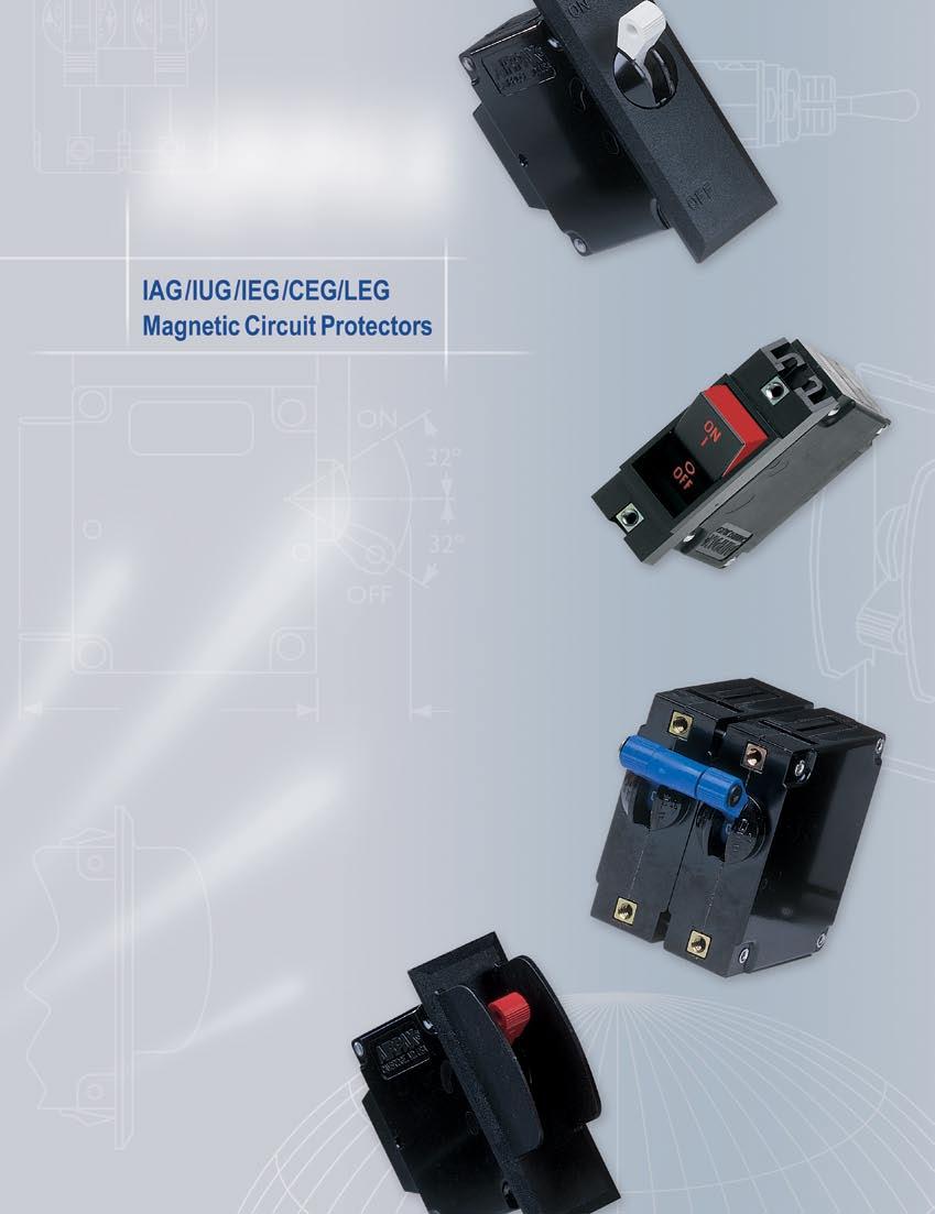
3 Single Pole Circuit PRTECTRS Magnetic Circuit Protectors provide low-cost power switching, reliable circuit protection and accurate circuit control for equipment in the international marketplace. IEG models meet IEC spacing requirements which is mandatory for equipment that must comply with IEC specifications 60 and 950 and VDE specifications 0804 and In addition, they are UL Recognized as supplementary protectors per UL STD. 077, CSA Certified as supplementary protectors per CSA C22.2 o. 235, VDE Approved to VDE 0642 (E60934), CCC Approved and CE Compliant. IAG models are for those applications where the unit s inherent attributes are desired, but compliance with the various standards is not required. Designed using the latest in sensitive hydraulic magnetic technology, the IAG/ IUG/IEG/CEG/LEG line adapts itself to many applications and environments. They re ideal for data processing and business machines, medical instrumentation, broadcast equipment, vending and amusement machines, military applications and wherever precision operation is required. Temperature differences which affect fuses and other thermal devices are not a concern. ne important feature of this protector line is a trip free action, which means the circuit will trip in the presence of an overload even though the handle is held in the position. The delay mechanism senses the fault and the contacts open. The is available in a wide variety of configurations including series, series with auxiliary switch, shunt and relay with a choice of delays and ratings in either DC, 50/60Hz or 400Hz versions. Handles come in seven different colors and international markings are standard. Single or multi-pole versions are available, with a variety of pole arrangements to meet your specifications. our pole models require a double toggle handle. Units with a handle per pole come in one through six pole assemblies. Single Pole Protector [50.80].590 [5.00].220 [3.00] [42.85] [52.7].660 [42.6].050 [26.67] 2X 0.56 [3.96].690 [7.53] 2X 6 32 THREAD.40 [3.56] DEEP M3 IS THD. PTIAL..660 [42.6] Single Pole Mounting Detail.240 [6.0] 32º 32º.68 [4.27] LEG Type Units Require Screw Terminals.530 [38.86].230 [5.84] ote: Tolerance ±.05 [.38] unless noted. Dimensions in brackets [ ] are millimeters. Single Pole Circuit Protectors 9
4 IAG / IUG / IEG / CEG / LEG Multi-Pole CIrcuit PRTECTRS Two Pole Protectors An assembly consisting of two single pole units, having their trip mechanisms internally coupled and with a single toggle handle, forms the IEG with quick-connect D.I..-style terminals. Individual poles may differ in ratings, delays and internal connections. An auxiliary switch may be included in either or both poles, allowing you to mix SELV and hazardous voltages. Rugged screw-type terminals can be provided, in which case the designation would be IEG66. The IEGH offers a toggle handle for each pole. LEG type units are avavailable only in one or two pole configurations. Three Pole and our Pole Protectors The three pole construction consists of three single pole units assembled with an internal mechanical interlock which actuates all units simultaneously. A single toggle handle operates all three poles for quick and convenient control, or if preferred, a handle per pole is available. The four pole construction consists of four single pole units assembled with an internal mechanical interlock which actuates all units simultaneously. A double toggle handle operates all four poles. The individual poles need not have identical characteristics and any series trip pole may have an auxiliary switch. If screw-type terminals are required, the breaker designation will be IEG666 for a three pole version and IEG6666 for a four pole version. Protectors poles are numbered consecutively when viewed from the terminal side, with the position up, starting with Pole # on the left side and proceeding to the right..687 [42.85].240 [6.0] Multi-Pole Circuit Breakers Two Pole* Three Pole* our Pole* [52.7].690 [7.53] LEG Type Units Require Screw Terminals 32º 32º.55 [38.48] (ptional: Handle may be located in Pole instead of Pole 2) [57.53] 3.05 [76.58].230 [5.84] X [ [ Two Pole* Three Pole* our Pole*.530 [38.86].660 [42.7].050 [26.68] 4X.56 [3.96] Panel Mounting Detail: Tolerance for Mtg. ±.005 [.3] unless noted. *See Single Pole Mounting Detail for hole sizes and locations. LEG type units are only available in one or two poles. ote: Tolerance ±.05 [.38] unless noted. Dimensions in brackets [ ] are millimeters. 92 Multi-Pole Circuit Protectors
5 IAGH / IUGH / IEGH / CEGH / LEGH Multi-Pole CIrcuit PRTECTRS IAGH/IUGH/IEGH/CEGH/LEGH Protectors The IAGH/IUGH/IEGH/CEGH/LEGH two, three and four pole models are available with a handle per pole. LEGH type units are available only in two pole models. IAGH/IUGH/IEGH/CEGH/LEGH Protectors.687 [42.85].240 [6.0] 2X.590 [5.00] 4X 6 32 THREAD.40 [3.56] DEEP M3 IS THD. PTIAL 32º 32º [50.80] [42.6].220 [3.00] [52.70].690 [7.53].68 [4.27].55 [38.48] [57.53] 3.05 [76.58] LEG Type Units Require Screw Terminals Panel Mounting Detail: Tolerance for Mtg. ±.005 [.3] unless noted. *See Two Pole Mounting Detail for hole sizes and locations. LEG type units are only available in one or two poles. Two Pole Three Pole* our Pole*.530 [38.86].230 [5.84] X [42.6].050 [26.67] 4X.56 [3.96] LEG/LEGH Barriers (required) In order to meet UL listing requirements, the LEG/LEGH two pole model requires barriers. Available with a standard straight barrier or an optional Z type barrier. Standard Barrier ptional Z Barrier ote: Tolerance ±.05 [.38] unless noted. Dimensions in brackets [ ] are millimeters. IAGH/IUGH/IEGH/CEGH/LEGH Multi-Pole Circuit Protectors 93
6 IAGX / IUGX / IEGX / CEGX / IAGZX / IUGZX / IEGZX / CEGZX / LEGZX RCKER CIrcuit PRTECTRS Rocker Protectors The IAGX/IUGX/IEGX/CEGX and IAGZX/IUGZX/IEGZX/CEGZX/ LEGZX styles offer two attractive rocker actuator versions of our popular family. Designed with the operator in mind, each features handles with a concave surface and aesthetic appearance for front panel applications. Both are available with rocker handle styles in a choice of five single colors: black, red, grey, orange or white. The IAGZX/IUGZX/IEGZX/CEGZX/LEGZX style adds our EZ options of contrasting dual color rocker actuators, affording a clear visual indication of the handle position and integrated handle guards, to help prevent accidental turn-on and turn-off of the unit. Available with a black rocker and white, red or green indicator color for either or indication. IAGX/IUGX/IEGX/CEGX Single Pole Two Pole Three Pole our Pole [50.80].687 [42.85].220 [30.99].972 [50.09] 6 32 THD. (TYP.) M3 IS THD. PTIAL.660 [42.6] [56.03].55 [38.48] [57.53] 3.05 [76.58] (ptional: Handle may be located in Pole 2 instead of Pole ) [62.74].490 [2.45] IAGZX/IUGZX/IEGZX/CEGZX/LEGZX ± [±.3] [8.67] (HADLE WIDTH) Mounting Detail Single, Two & Three Pole.200 [5.08] 2X.56 [3.96].660 [42.6].260 [32.00] our Pole*.50 [38.35] Panel Mounting Detail: Tolerance for Mtg. ±.005 [.3] unless noted. *See Single Pole Mounting Detail for hole sizes and locations. Single Pole* Two Pole* Three Pole Single, Two & Three Pole [50.80].530 [38.86] [62.74].687 [42.85].430 [0.92].420 RE. [0.67].25 [3.8].220 [30.99] 2.65 [54.98] PTIAL HADLE GUARDS (SEE DETAIL A ).239 [3.47] 6 32 THD. (TYP.) M3 IS THD. PTIAL.660 [42.6].55 [38.48] Max. [57.53].200 [5.08] 2X.56 [3.96].660 [42.6].260 [32.00] Panel Mounting Detail: Tolerance for Mtg. ±.005 [.3] unless noted. * LEG type units are only available in one or two poles. Detail A ote: Tolerance ±.05 [.38] unless noted. Dimensions in brackets [ ] are millimeters. 94 IAGX/IUGX/IEGX/CEGX/IAGZX/IUGZX/IEGZX/CEGZX/LEGZX Rocker Circuit Protectors
7 IAGBX / IUGBX / IEGBX / CEGBX / LEGBX RCKER CIrcuit PRTECTRS The innovative new design of our IEG BX style circuit breaker features a flat front rocker that not only satisfies your aesthetic needs, it guards against accidental actuation while providing the highest degree of circuit protection and quality. nly Airpax offers this new standard in user interface, providing additional peace of mind that guards alone can t supply. Available on a variety of versions with a full range of agency approvals, the new IEG BX style circuit breakers meet or exceed all current performance specifications, including interrupting capacities up to 50,000 amperes. Various guard options offer additional and increasing levels of actuation protection performance. The two shot mold on the flat rocker surface provides a clean, crisp legend that can withstand demanding use. IAGBX/IUGBX/IEGBX/CEGBX/LEGBX I I MAX [60.40].387 RE. [9.84] ACTUATI ACCESS HADLE (SEE TE) PSITI "" WITH GUARD (SIXTH DECISI, G) HADLE PSITI "" WITH GUARD (SIXTH DECISI, G) [50.80].530 [38.86].687 [42.85].34 [7.98].25 [3.8].220 [30.99].239 [3.47] I PUSH T RESET I PUSH T RESET HADLE HADLE PSITI "" PSITI "" GUARD WITH ACTUATE GUARD WITH ACTUATE EATURE EATURE (SIXTH DECISI, X) (SIXTH DECISI, X) 6-32 THD. MUTIG M3 IS THD. PTIAL 2X ÿ.56 [3.96] I I 2.27 [56.3] I.660 [42.6].660 [42.6].200 [5.08].260 [32.00] HADLE PSITI "" WITHUT GUARD DETAIL "A" TE: ACCESS IS LIMITED T A DEVICE SMALLER THA THE UDERWRITERS LABRATRY "ARTICULATED PRBE" DEIED I UL-489 IG HADLE PSITI "" WITHUT GUARD PTIAL GUARD (SEE DETAIL ìcî) SIGLE PLE Panel Mounting Detail MUTIG DETAIL TLERACE: ±.005 [.3] ULESS TED IAGBX/IUGBX/IEGBX/CEGBX/LEGBX Rocker Circuit Protectors 95
8 IAG SEALED TGGLE CIrcuit PRTECTRS The IAG/IUG family is a sealed toggle version of the IAG/ IUG family. The silicone rubber seal around the handle assures panel seal integrity and makes this style a natural for harsh environments. This sealed toggle family is available in one to three poles with ratings of.050 to 50 amperes. Single Pole Two Pole Three Pole.30 [3.30] 6 32 MTG. SCREW R HIGH SHCK MTG. KEYWAY.060 [.52].065 [.65] WIDE.030 [.76].035 [.89] DEEP.55 [38.48] [57.53] [57.30].625 [5.88] LCKWASHER ±3º 3º ±3º 3º /2 32 HEX UT RUBBER RIG [50.80].220 [30.99].656 [6.66] (ptional: Handle may be located in Pole 2 instead of Pole ) ptional Handle Mounting Detail Single Pole Two Pole* Three Pole*.56 [3.96].55 [3.08].656 [6.66] Panel Mounting Detail: Tolerance for Mtg. ±.005 [.3] unless noted. *See Single Pole Mounting Detail for hole sizes and locations. ote: Tolerance ±.05 [.38] unless noted. Dimensions in brackets [ ] are millimeters. 96 IAG Sealed Toggle Circuit Protectors
9 IEGS / IEGHS / CEGS / CEGHS / LEGS / LEGHS Snap-In Circuit PRTECTRS The Snap-In version of the IEG brings mounting simplification and international spacing together in a package that is aesthetically enhanced. The IEGS securely snaps into a rectangular cut-out, eliminating the need for panel mounting hardware and the associated costs. The face plate of the IEGS is a clean, black matte and it satisfies the increasing demand for front panel components that are designed with ergonomic considerations. The IEGS is offered in either flush or beveled versions, in, 2, 3 or 4 pole packages, and with a handle per pole or per unit. The IEGS is UL Recognized, CSA Certified and VDE approved. Please see pages 98 and 99 for complete specifications. IEGHS/CEGHS/LEGHS Circuit Protectors (ote B) (Multi-Pole-IEGH Handles Per Pole) (mit H for Single Pole).687 [42.85].240 [6.09].744 [8.90].488 [37.80] [56.69] [75.59] [50.80].220 [30.99] [52.70] 32º 32º.690 [7.53] Panel Cutout Detail Panel Thickness: (See Table) [65.99] umber of Poles pole Dimension A max. DIM. B (SEE TABLE) 2 pole 3 pole.55 max. [38.48] max. [57.53] DIM. C (SEE TABLE) 4 pole 3.05 max. [76.58] DIM. A (SEE TABLE).27 [3.23] umber of Poles Dimension B Dimension C pole 2 pole.755 min. [9.8].520 min. [38.6] 2.80 ±.005 [55.37 ±.3] 2.86 ±.0 [55.52 ±.28] 3 pole min. [57.66] ote: A: lush face plate is optional. See decision tables, sixth decision, page 0. B: Tolerance ±.03 [.79] Angles: ±5 unless noted. Dimensions in brackets [ ] are millimeters. 4 pole Panel Thickness min. [76.7] [ ] [.52 ± 2.54] IEGS/IEGHS/CEGS/CEGHS/LEGS/LEGHS Snap-In Circuit Protectors 97
![IEGS / IEGHS / CEGS / CEGHS / LEGS / LEGHS Snap-In Circuit PRTECTRS IEGS/CEGS/LEGS Circuit Protectors (ote B) (Add H for multiple handles per unit, IEGHS).687 [42.85].240 [6.09].960 [24.38].700 [43.](/docs-images/79/79714202/images/10-0.jpg "8] 2.450 [62.23] 3.90 [8.03] 2.000 [50.80].220 [30.99] 32º 32º 2.598 [65.99] 2.075 [52.70].690 [7.53] Panel Cutout Detail Panel Thickness: (See Table) umber of Poles pole Dimension A max. DIM.")
10 IEGS / IEGHS / CEGS / CEGHS / LEGS / LEGHS Snap-In Circuit PRTECTRS IEGS/CEGS/LEGS Circuit Protectors (ote B) (Add H for multiple handles per unit, IEGHS).687 [42.85].240 [6.09].960 [24.38].700 [43.8] [62.23] 3.90 [8.03] [50.80].220 [30.99] 32º 32º [65.99] [52.70].690 [7.53] Panel Cutout Detail Panel Thickness: (See Table) umber of Poles pole Dimension A max. DIM. B (SEE TABLE) DIM. A (SEE TABLE).30 [3.30] 2 pole 3 pole 4 pole.55 max. [38.48] max. [57.53] 3.05 max. [76.58] DIM. C (SEE TABLE) umber of Poles pole 2 pole 3 pole Dimension B.780 ±.05 [9.8 ±.38].540 ±.05 [39.2 ±.38] ±.05 [58.7 ±.38] Dimension C 2.80 ±.005 [55.37 ±.3] 2.86 ±.0 [55.52 ±.28] 4 pole ±.05 [77.22 ±.38] Panel Thickness [ ] [.52 ± 2.54] ptional Handle Guard.780 [9.82].560 [39.62].734 [8.64] ote: A: Tolerance ±.05 [.38] unless noted. Dimensions in brackets [ ] are millimeters. B: Bevelled face plate is standard. 98 IEGS/IEGHS/CEGS/CEGHS/LEGS/LEGHS Snap-In Circuit Protectors

11 IAG / IUG / IEG / CEG / LEG Configurations Series Trip The most popular configuration for magnetic protectors is the series trip where the sensing coil and contacts are in series with the load being protected. The handle position conveniently indicates circuit status. In addition to providing conventional overcurrent protection, it s simultaneously used as an on-off switch..530 [38.86].230 [5.84] Series.530 [38.86].230 [5.84] Switch nly Shunt Trip The shunt trip is designed for controlling two separate loads with one assembly. The control is established by providing overload protection for the critical load. When the current through this load becomes excessive and reaches the trip point, the protector will open and remove power from both loads simultaneously. The total current rating of both loads must not exceed the maximum contact rating. Auxiliary Switch (Applies to Series Trip nly) This is furnished as an integral part of a series pole in single or multi-pole assemblies. Isolated electrically from the protector s circuit, the switch works in unison with the power contacts and provides indication at a remote location of the protector s on-off status. Auxiliary switch contacts actuate simultaneously with the main protector contacts, and will open regardless of whether the protector contacts are opened manually or electrically. or auxiliary switch ratings below 6Vac or 5Vdc, an auxiliary switch with gold contacts designated as REG is available. Gold contacts are not recommended for load current above 00 milliamps. ptional flat screw terminal.230 [5.84].380 [35.05] Standard Auxiliary Switch.083 [27.5].848 [2.53].44 [.20].530 [38.86].059 [26.90].764 [9.04] 2.52 [64.00] (See ote A) VDE Auxiliary Switch.469 [.9] Shunt Main Terminal Types Amp Rating A A Push-on 8-32 Screw M4 Screw X X X 0-32 Screw X M5 Screw X.0 [2.79] [6.93] (See ote A).260 [6.60] IREC4 IREG4.87 [4.75] IREC [62.33] (See ote A).250 [6.35] Series with Auxiliary Switch C ote: A: Terminal protrusion dimensions are referenced from back mounting panel. B: Main terminals are male push-on type.250 [6.35] wide x 0.3 [.79] thick x.375 [9.53] long or 8-32 x.87 [4.75] screw type. Metric screw terminals are M4 x 5mm (<=30A): M5 x 5mm screw type (>30A). n VDE approved builds with screw terminals, external tooth lockwashers are supplied. n VDE approved builds with push-on terminals a soldered connection is required above 25 amperes. C BREAKER I PSITI Configurations 99
12 IAG / IUG / IEG / CEG / LEG Configurations Relay Trip This permits the overload sensing coil to be placed in a circuit which is electrically isolated from the trip contacts. The coil may be actuated by sensors monitoring pressure, flow, temperature, speed, etc. ther typical applications include crowbar, interlock and emergency /rapid shutdown circuitry. Trip may be accomplished by voltage or current, which must be removed after trip..380 [35.05].230 [5.84].620 [5.75].530 [38.86] 2.52 [64.00] (See ote A) Relay.230 [5.84] 2.52 [64.00] (See ote A).380 [35.05] Dual Coil.530 [38.86] Dual Coil By combining two electrically independent coils on a common magnetic circuit, it is possible to provide contact opening when either an over-current or trip voltage is applied to the respective coils. ne coil will be a current trip coil with standard specifications. The second, or dual coil, can be used to provide a control function permitting contact opening from a remote interlock or other transducer functions. Standard coils are 6, 2, 24, 48, 20 and 240 volts. Tripping is instantaneous and must be removed (usually self-interrupting) after trip..380 [35.05].230 [5.84].620 [5.75].530 [38.86] 2.52 [64.00] (See ote A) Dual Coil ptional Barriers (IEG nly) Voltage Trip Sometimes called dump circuits or panic trip circuits, these units make it possible to open main power contacts with lower power inputs from one or more sources. This configuration is becoming increasingly more important for sensitive circuitry and denser packaging in automation systems. Available in series, shunt or relay configurations..57 [4.50] [50.80] ote: Tolerance ±.05 [.38] unless noted. Dimensions in brackets [ ] are millimeters. 00 Configurations
13 IAG / IUG / IEG / CEG / LEG operating characteristics Delay Pulse Tolerance 6, 62, 63, 7, 72, 73 0 times (approx.) rated current 6, 62, 63, 7, 72, 73 2 times (approx.) rated current 64, 65, times (approx.) rated current Inrush Pulse Tolerance The following table provides a comparison of inrush pulse tolerance with and without the inertial delay feature for each of the 50/60Hz delays. Pulse tolerance is defined as a single pulse of half sine wave peak current amplitude of 8 milliseconds duration that will not trip the circuit breaker. The table at left provides a guide to determine if the inertia delay feature is required. Consult factory for further assistance. Typical Protector Resistance/Impedance Chart Current ratings in amperes DC Resisitance - hms 5, 52, 53, 59 50/60Hz Impedance - hms 400Hz* Impedance - hms 6, 62, 63, 69 4, 42, 43, otes: DCR and Impedance based on 00% rated current applied and stabalized for a minimum of one hour. Tolerance amperes ± 20%: amperes ± 25%, 2-50 amperes ± 50%. Consult factory for special values and for coil impedance of delays not shown. Percentage verload vs Trip Time in Seconds Delay % 25% May trip May trip 50% % % % % % May trip May trip.00 max..050 max..020 max..020 max..020 max..020 max. 5* * * *.20 max..00 max..050 max..022 max..07 max..07 max..07 max. 6* * * *.20 max..00 max..050 max..022 max..07 max..07 max..07 max. 7** ** ** **.20 max..00 max..050 max..023 max..06 max..05 max..05 max. *CEG type units are available only with 5, 52,,53 and 59 delays **35% minimum trip point for delays 7, 72, 73 and 79 LEG type units are available only with 6, 62, 63 and 69 delays perating Characteristics 0
14 IAG / IUG / IEG / CEG / LEG DELAY CURVES 400Hz, DC, 50/60Hz Delay Curves (typ) A choice of delays is offered for DC, 50/60Hz and 400Hz applications. Delays 49, 59 and 69 provide fast acting, instantaneous trip and are often used to protect sensitive electronic equipment (not recommended where known inrush exists). Delays 4, 5 and 6 have a short delay for general purpose applications. Delays 42, 52 and 62 are long enough to start certain types of motors and most transformer and capacitor loads. Delays 43, 53 and 63 are long delays for special motor applications at 400Hz, DC and 60Hz. CEG type units are only available in 5, 52, 53 and 59 delay curves. LEG type units are only available in 6, 62, 63 and 69 delay curves DELAY 6 00 DELAY 62 TIME I SECDS PERCET RATED CURRET TIME I SECDS PERCET RATED CURRET 0 DELAY 63 0 DELAY TIME I SECDS 0. TIME I SECDS PERCET RATED CURRET PERCET RATED CURRET 02 IAG/IUG/IEG/LEG Delay Curves
15 IAG / IUG / IEG / CEG DELAY CuRves DC Delay Curves (typ) 0 00 TIME I SECDS 0. DELAY PERCET RATED CURRET 0 00 DELAY TIME I SECDS MAY DELAY 53 PERCET RATED CURRET DELAY 59 TIME I SECDS 0. TIME I SECDS PERCET RATED CURRET PERCET RATED CURRET IAG/IUG/IEG/CEG Delay Curves 03

16 IAG / IUG / IEg DELAY CURVES DC/50/60Hz Delay Curves (typ) (Multi-frequency) 0 0 TIME I SECDS DELAY PERCET RATED CURRET 900 TIME I SECDS DELAY PERCET RATED CURRET DELAY 73 DELAY 79 TIME I SECDS 00 0 TIME I SECDS PERCET RATED CURRET IAG/IUG/IEG Delay Curves
17 IAG / IUG / IEG DELAY CURVES 400Hz Delay Curves (typ) 0 0 DELAY 4 DELAY 43 TIME I SECDS PERCET RATED CURRET TIME I SECDS PERCET RATED CURRET DELAY DELAY 49 TIME I SECDS 0. TIME I SECDS PERCET RATED CURRET PERCET RATED CURRET IAG/IUG/IEG Delay Curves 05

18 IAG / IUG / IEG / CEG / LEG SPECIICATIS Trip ree Will trip open on overload, even when forcibly held in the position. This prevents the operator from damaging the circuit by holding on the protector. Trip Indication The operating handle moves positively to the position on overload. Ambient peration protectors operate in temperatures between 40 C to +85 C. Insulation Resistance ot less than 00 megohms at 500 volts DC. Dielectric Strength protectors withstand 3750Vac, 60Hz for 60 seconds between all electrically isolated terminals, except auxiliary switch terminals shall withstand 600Vac, 60Hz for REG and REC types. our terminal dual coil and relay construction (not offered in the IEG) will withstand 500Vac. Endurance perating as a switch, the operating life exceeds 0,000 operations at a rate of 6 per minute when tested as follows: 6000 rated current plus 4000 at no load. Electrical Characteristics amperes; 80Vdc Max., 240Vac Max., 50/60Hz and amperes: 250Vac Max., 400Hz. Units above 30 amps are not suitable for across-the-line motor starting. Auxiliary Switch When supplied shall be SPDT configuration. on VDE approved switches have a maximum UL rating of 0.0 amperes, 250 volts, 60Hz; 3.0 amperes, 50 volts DC, amperes, 80 volts DC (REC) type or 0. amperes, 25 volts, 60Hz. (REG type). VDE approved switches have a maximum UL rating of 0.0 amperes, 250 volts, 60Hz, amperes, 80 volts DC (REG type); or 0. amperes, 25 volts, 60Hz (REG type); or 0. amperes, 25 volts, 60Hz (REG type). Moisture Resistance Meets all the requirements of MIL-PR when tested in accordance with Method 06 of MIL-STD-202. Salt Spray (Corrosion) Meets the requirements of MIL-PR when tested in accordance with Method 0 of MIL-STD-202. Shock Circuit protectors shall not trip when tested per MIL-STD-202, Method 23, Test Condition I with 00% rated current applied to delayed units, except 90% current in plane 4 (i.e., handle down). Instantaneous units shall have 80% rated current applied in all planes. Vibration Circuit protector shall not trip when vibrated per MIL-STD-202, Method 204, Test Condition A with 00% rated current applied to delayed units and 80% rated current to instantaneous units. Construction Series, shunt, relay and series with auxiliary switch available in various delays and combinations. VDE Approval IEG is VDE approved under VDE 0642 (E60934). The IEG has 8mm creepage and clearance between the main circuit and the following areas: A. perator accessible area around the handle. B. The mounting inserts or brackets. C. The auxiliary switch circuit. D. Between poles. Care must be taken to maintain spacings at the terminals when wired. The VDE approval for standard terminals is not for use with bare wire. A crimp type lug is required. In addition, all VDE approved units will be in compliance with specific CE Directives. These units will be marked as CE Compliant. UL500 (Marine Ignition Protected) IDG/IDGH is approved for Marine Ignition Protection rated at 65Vdc or 25/250Vac to 30 amperes with amperes maximum interrupt capacity or 32Vdc with 3000 amperes maximum interrupt capacity. UL489A Listed The CEG is dimensionally the same as the popular IEG, but provides UL listing to UL489A. Available in one to three poles, in series, series with auxiliary switch, shunt, dual coil and voltage trip configurations. As a circuit breaker, the CEG provides communication equipment manufacturers with a UL listed circuit breaker in a very compact package that meets the stringent environmental requirements of today s marketplace. This makes the CEG ideal for switching, transmission and wireless applications. UL489 Listed The LEG is dimensionally the same as the popular IEG, but provides UL listing to UL489. Available with one or two poles, in series, series with auxiliary switch, shunt and three-terminal dual coil configurations. As a circuit breaker, the LEG provides equipment manufacturers with a UL listed magnetic hydaulic circuit breaker in the most compact package available on the market. 06 Specifications
19 IAG / IUG / IEG / CEG / LEG SPECIICATIS Agency Approvals Current (A) Short Circuit Current Rating (SC) IAG/IUG/IEG Supplementary Protectors Voltage requency (Hz) Phase Min. Poles UL/CSA VDE UL077 & CSA VDE 80 DC U2, / U2, / C, 5000(3) / U3, - 25/250 50/ U, /250 50/60 2/-30/5 - C2, 5000() /60 & U, /60 & C2, 5000() / U2, /60 & U, /60 & C2, 3500(2) - 250(4) 50/60 & C, 3500(2) - 250(4) 50/60 & U, - 250(5) 50/ U3, - 250(5) 50/ U3, / U2, / C2, 5000(2) & U2, IDG Supplementary Protectors Voltage requency (Hz) Phase Min. Poles UL/CSA VDE UL077 & CSA VDE 48 DC U2, DC U2, / U2, /250 50/ U2, /60 & U, - CEG Communications Equipment Circuit Breakers Voltage requency (Hz) Phase Min. Poles UL/CSA VDE UL077 & CSA VDE 80 DC LEG Circuit Breakers Voltage requency (Hz) Phase Min. Poles UL/CSA VDE UL489A VDE 25 50/ /240 50/ () With 25 A max. series fuse; (2) With 80 A max. series fuse; (3) With 50 A max. circuit breaker; (4) With blocked vent construction; (5) on-standard construction. it for further use approval Recommended Torque Specifications General notes: Poles ne through six poles available. Approximate Weight Per Pole unces 2.2 Grams 62.4 All supplementary protectors are of the overcurrent (C) type The family of protectors has been evaluated for end use application for use groups (UG) A, B, C and D The terminals (W) are suitable for factory wiring only (0) The maximum voltage ratings for which the protectors have been tested are shown in the chart The current is the amperage range that the protectors have been tested The tripping current (TC) for all of the protectors is (in the range of 25% to 35% of ampere rating except for the 400Hz protectors which is 2 (more than 35% of ampere rating) The overload rating (L) - designates whether the protector has been tested for general use or motor starting applications mounting inserts M3 mounting inserts 8-32 screw terminals M4 screw terminals 0-32 screw terminals M5 screw terminals 6-8 inch pounds 4-5 inch pounds 0-2 inch pounds 0-2 inch pounds 4-5 inch pounds 4-5 inch pounds ote: Where applicable, mechanical support must be provided to terminals when applying torque. 0 tested at.5 times amp rating for general use tested at 6 times AC rating or 0 times DC rating for motor starting The short circuit current rating (SC) The short circuit rating in amperes following a letter and number designating the test conditions and any calibration following the short circuit test is defined below: C Indicates short circuit test was conducted with series overcurrent protection U Indicates short circuit test was conducted without series overcurrent protection Indicates a calibration was not conducted as part of the short circuit testing 2 Indicates a calibration was performed as part of the short circuit testing 3 Indicates recalibration was performed along with the dielectric and voltage withstand for Suitable for urther Use rating Specifications 07
20 IAG / IUG / IEG / CEG DECISI TABLES How to rder The ordering code for IAG/IUG/IEG/CEG/IDG circuit protectors may be determined by following the decision steps in the tables shown here. The coding given permits a self-assigning part number but with certain limitations. Special applications may require a factory-assigned part number. Typical examples are units with mixed ratings, combinations of styles, or constructions not listed in the third decision table. With these, it is suggested that order entry be by description and/or drawings and a part number will be established. Additionally, it is standard policy to establish a factoryassigned part number whenever a descriptive drawing exists to provide cross reference, traceability and manufacturing control. When specifying a circuit protector for AC motor start or high inrush applications, the peak amplitude and surge duration should be specified for factory assistance in rating selection. or example, the following is the code for a single pole, IEG quick-connect type terminal, series unit with auxiliary switch, designed for operation in a 50/60Hz circuit. It has a short time delay, a rating of 20 amperes, a black marked handle and is VDE approved. To determine the ordering number for your particular IAG/IUG/IEG/CEG unit, simply follow the steps shown. You may use this number to place an order or as a reference for further questions you may have. otes: A. It is recommended that power leads be soldered to circuit protectors having push-on type terminals for current trip ratings above 20 amperes. B. When A (metric thread mounting) is specified in the sixth decision in combination with screw terminal option in the second decision, metric screw terminals are supplied. C. IEG, IEGH, IEGS, IEGHS, IEGX and IEGZX circuit protectors are designed to meet 8mm creepage and clearance requirements for installation Category III, Pollution Degree 3, Case A as measured in IEC 664. Intended for use in equipment designed to comply with IEC 60 and 950 and VDE 0804 and Type Third Decision Internal Configuration -REC4 -REC5 -REG4 -RS4 -RLS irst Decision Select Type and Terminal IAG IUG* IEG** CUG+ CEG++ IAGH IUGH* IEGH** CUGH+ CEGH++ IDG*** IDGH*** IMG** CMG++ IMGH** CMGH++ Description ne toggle handle per unit ne toggle handle per pole ne toggle handle per unit, marine ignition protection ne toggle handle per pole marine ignition protection ne toggle handle per unit mid-trip indication ne toggle handle per pole mid-trip indication *UL Recognized, CSA Certified **UL Recognized, CSA Certified, VDE Approved *** UL Recognized UL500 + UL489A Listed CSA Certified ++ UL489AListed CSA Certified VDE Approved Switch only Series Series w/ auxiliary switch *.0 quick connect Series w/ auxiliary switch *.87 quick connect Series w/ auxiliary switch (gold contacts)*.0 quick connect Series w/ alarm switch, electrical trip,.0 Q.C. terminals Series w/ alarm switch, electrical trip,.0 Q.C. terminals (mid-trip only) Shunt Relay * nly one auxiliary switch is normally supplied on two or three pole units. Switch is located in the right-hand pole (viewed from terminal end) unless otherwise specified. S X Handle and Mounting ptions ZX BX Standard toggle/mounting, no designation required Toggle w/ snap-in mounting Rocker w/ standard mounting* ZX Rocker w/ integral mounting* BX Rocker w/ integral mounting Sealed toggle w/bushing mounting** ote: Add "" for flat screw terminals * ot available on mid-trip units ** Available only on IAG, IUG units 2 *ot available in toggle seal handle type. Example: IEG - REC V SW Second Decision Poles and Terminals Push-on Terminals ourth Decision requency and Delay Switch only Screw Terminals Hz short delay 400Hz long delay 400Hz motor start 400Hz 50% instant trip DC short delay* DC long delay* DC motor start* DC 25% instant trip* 50/60Hz short delay 50/60Hz long delay 50/60Hz motor start 50/60Hz 25% instant trip DC/60Hz short delay DC/60Hz long delay DC/60Hz motor start Single pole Two pole Three pole our pole DC/60 Hz 35% instant trip or addition of inertial delay, add an ìî to any delay numeral. * CEG types are only available with DC ratings 5 7 C = CCC Approved This approval requires the addition of a C at the end of the part number. The unit will not be VDE Approved. V = VDE and CCC Approved The shaded areas denote VDE and CCC (if applicable) Approval options. This approval requires the addition of a V at the end of the part number. The V will be added to any part number formed entirely from shaded decisions. If non-shaded areas are selected, the unit will not be VDE or CCC Approved, but other approvals still apply. 08 IAG/IUG/IEG/CEG Decision Tables
21 5 ifth Decision Rated Current Standard ratings listed. or other ratings, please contact the factory * 40.0* 6 -A -B -C -G -L Sixth Decision ptional Standard hardware. o designation required. Metric thread mounting inserts and terminals Barriers* 277V (50/60Hz only) (See note 3) Handle guard, (available in ZX, BX and snap-in versions only) Handle lock IDICATI MUTIG/IDICATR CDE: IDICATI A, B, C MUTIG/IDICATR CDE:, G, H LAD RCKER HADLE CLR IDICATIG CLR LAD LAD IG. 2 IG. 3 IG. 4 IG. 5 IG. IG. 6 LAD IDICATIG CLR RCKER HADLE CLR * -M Handle in opposite pole MARKIG DETAIL A (SEE TABLE) Q APG style AT handle * IDG/IDGH is rated for 30 amps max. 7 Seventh Decision Handle Color and Marking Selection Toggle Handle Color Unmarked Marked - I- -S -X ace plate sides flush with protector (see note 4) Handle guard with no actuation feature (BX rocker only) (ot available with mid-trip indication) otes:. ne or more descriptions may be used as required. 2. When this is not used, table one may be substituted and U.S. thread will be supplied. Unit will be rated at 250V (50/60Hz only.) 3. VDE approved at 250VAC 4. IEGS standard face plate has beveled sides(see pg.90) * ot available on snap-in units LAD IG. 2 IG. 3 IG. 4 IG. 5 IG. IG. 6 IDICATIG CLR RCKER HADLE CLR IDICATI MUTIG/IDICATR CDE: J, K, L LAD LAD LAD (STD) MARKIG DETAIL B (SEE TABLE) Yellow Blue I Green range IDICATI MUTIG/IDICATR CDE: M,, P, R Handle marking color is white on black, red, blue & green handles and black on white, yellow and orange handles. See alternate 7th decision below for X, ZX & BZ rocker handles. LAD IG. 2 IG. 3 IG. 6 LAD 7 Rocker Handle Color Seventh Decision Rocker Handle Color, Indicator Color and Marking Selection (See otes) IAGX, IUGX, IEGX, IAGZX, IUGZX, IEGZX, CUGZX, CEGZX Rocker Handle (Single Rocker Color) Indicating Color Marking Color Indicates: Unmarked Vertical Mounting n-ff ig. I- ig.2 n-ff I- ig.3 Horizontal Mounting n-ff ig.4 I- ig.5 n-ff I- ig.6 MARKIG DETAIL C (SEE TABLE) Marking Detail Grey range A IAGZX, IUGZX, IEGZX, CUGZX, CEGZX Rocker Handle (Dual Rocker Color) n -A0 -A -A2 -A3 -A4 -A5 -A6 Green n n ff -B0 -C0-0 -B -C - -B2 -C2-2 -B3 -C3-3 -B4 -C4-4 -B5 -C5-5 -B6 -C6-6 A ff -G0 -G -G2 -G3 -G4 -G5 -G6 Green ff -H0 -H -H2 -H3 -H4 -H5 -H6 Green n n n -J0 -K0 -L0 -J -K -L -J2 -K2 -L2 -J3 -K3 -L3 -J4 -K4 -L4 -J5 -K5 -L5 -J6 -K6 -L6 B IAGBX, IUGBX, IEGBX, CUGBX, CEGBX Rocker Handle (Dual Rocker Color) ff -M0 -M2 -M3 -M6 Green Green ff ff -0 -P0-2 -P2-3 -P3-6 -P6 C Yellow Yellow ff -R0 -R2 -R3 -R6 otes: A. Bezels of IAGBX, IUGBX, IEGBX, CUGBX, CEGBX are black. B. Consult factory for other marking options. IAG/IUG/IEG/CEG Decision Tables 09

22 LEG Decision Tables irst Decision How to rder Select Type and Terminal Type Description Handle and Mounting ptions The ordering code for LEG circuit breakers may be determined by following the decision steps in the tables shown here. The coding given permits a self-assigning part number but with certain limitations. Special applications may require a factory-assigned part number. Typical examples are units with mixed ratings, combinations of styles, or constructions not listed in the third decision table. With these, it is suggested that order entry be by description and/or drawings and a part number will be established. Additionally, it is standard policy to establish a factoryassigned part number whenever a descriptive drawing exists to provide cross reference, traceability and manufacturing control. When specifying a circuit breaker for AC motor start or high inrush applications, the peak amplitude and surge duration should be specified for factory assistance in rating selection. or example, the following is the code for a single pole, LEG screw type terminal, series unit with auxiliary switch, designed for operation in a 50/60Hz circuit. It has a short time delay, a rating of 20 amperes, a black marked handle and is VDE approved. To determine the ordering number for your particular LEG unit, simply follow the steps shown. You may use this number to place an order or as a reference for further questions you may have. LEG ne toggle handle per unit ne toggle handle per unit LMG mid-trip indication LEGH ne toggle handle per pole ne toggle handle per pole LMGH mid-trip indication ote: All types are UL489 listed, CUL certified 3 - Third Decision Internal Configuration -REC4 -REC5 -REG4 Series Series w/ auxiliary switch *.0 quick connect Series w/ auxiliary switch *.87 quick connect Series w/ auxiliary switch* (gold contacts).0 quick connect Standard toggle/mounting, no designation required S Toggle w/ snap-in mounting ZX ZX Rocker w/ integral mounting* BX BX Rocker w/ integral mounting ote: Add "" for flat screw terminals * ot available on mid-trip units 2 Second Decision Poles and Terminals Screw Terminals 6 Single pole 66 Two pole* *Supplied with standard barrier Example: LEG 6 - REC V ourth Decision requency and Delay 50/60Hz short delay 50/60Hz long delay 50/60Hz motor start 50/60Hz 25% instant trip or addition of inertial delay, add an to any delay numeral. * CEG types are only available with DC ratings 5 7 otes: A. When A (metric thread mounting) is specified in the sixth decision in combination with screw terminal option in the second decision, metric screw terminals are supplied. B. LEG, LEGH, LEGS, LEGHS, LEGZX and LEGBX circuit breakers are designed to meet 8mm creepage and clearance requirements for installation Category III, Pollution Degree 3, Case A as measured in IEC 664. Intended for use in equipment designed to comply with IEC 60 and 950 and VDE 0804 and RS4 -RLS4-3 Series w/ alarm switch*, electrical trip,.0 Q.C. terminals Series w/ alarm switch*, electrical trip, mid-trip only,.0 Q.C. terminals Shunt * nly one auxiliary switch is normally supplied on two pole units. Switch is located in the right-hand pole (viewed from terminal end) unless otherwise specified. V = VDE and CCC Approved The shaded areas denote VDE and CCC (if applicable) Approval options. This approval requires the addition of a V at the end of the part number. The V will be added to any part number formed entirely from shaded decisions. If non-shaded areas are selected, the unit will not be VDE or CCC Approved, but other approvals still apply. C = CCC Approved This approval requires the addition of a C at the end of the part number. The unit will not be VDE Approved. 0 LEG Decision Tables
23 5 ifth Decision Rated Current 6 Sixth Decision ptional RCKER HADLE CLR IDICATIG CLR Standard ratings listed. or other ratings, please contact the factory A -G -L -S -X* -Z Standard hardware. o designation required. Metric thread mounting inserts and terminals Handle guard, (available in ZX, BX and snap-in versions only) Handle lock ace plate sides flush with breaker Handle guard with no actuation feature (BX rocker only) "Z" Barriers IDICATI MUTIG/IDICATR CDE: IDICATI A, B, C MUTIG/IDICATR CDE:, G, H LAD IDICATIG CLR LAD LAD IG. 2 IG. 3 IG. 4 IG. 5 IG. IG. 6 MARKIG DETAIL A (SEE TABLE) LAD RCKER HADLE CLR otes:. ne or more descriptions may be used as required. 2. When this is not used, table one may be substituted and U.S. thread will be supplied. Unit will be rated at 250V (50/60Hz only.) 3. LEGS standard face plate has beveled sides(see pg. 90) * ot available on mid-trip units IDICATIG CLR RCKER HADLE CLR 7 Seventh Decision Handle Color and Marking Selection IDICATI MUTIG/IDICATR CDE: J, K, L Toggle Handle Color Unmarked Marked - I- LAD LAD LAD LAD IG. 2 IG. 3 IG. 4 IG. 5 IG. IG (STD) MARKIG DETAIL B (SEE TABLE) Yellow Blue Green I range IDICATI MUTIG/IDICATR CDE: M,, P, R Handle marking color is white on black, red, blue & green handles and black on white, yellow and orange handles. See alternate 7th decision below for ZX & BZ rocker handles. LAD LAD IG. 2 IG. 3 IG. 6 MARKIG DETAIL C (SEE TABLE) 7 Rocker Handle Color Seventh Decision Rocker Handle Color, Indicator Color and Marking Selection (See ote) LEGZX Rocker Handle (Single Rocker Color) Indicating Color Marking Color Indicates: Unmarked Vertical Mounting n-ff ig. I- ig.2 n-ff I- ig.3 Horizontal Mounting n-ff ig.4 I- ig.5 n-ff I- ig.6 Marking Detail Grey range A LEGZX Rocker Handle (DUal Rocker Color) n -A0 -A -A2 -A3 -A4 -A5 -A6 Green n n ff -B0 -C0-0 -B -C - -B2 -C2-2 -B3 -C3-3 -B4 -C4-4 -B5 -C5-5 -B6 -C6-6 A ff -G0 -G -G2 -G3 -G4 -G5 -G6 Green ff -H0 -H -H2 -H3 -H4 -H5 -H6 Green n n n -J0 -K0 -L0 -J -K -L -J2 -K2 -L2 -J3 -K3 -L3 -J4 -K4 -L4 -J5 -K5 -L5 -J6 -K6 -L6 B LEGBX Rocker Handle (Dual Rocker Color) ff -M0 -M2 -M3 -M6 Green Green ff ff -0 -P0-2 -P2-3 -P3-6 -P6 C Yellow Yellow ff -R0 -R2 -R3 -R6 otes: A. Bezels of LEGBX are black. B. Consult factory for other marking options. LEG Decision Tables
24
IAG/IUG/IEG/CEG/LEG Series
 IAG/IUG/IEG/CEG/LEG Series Magnetic Circuit Protectors Introduction Poles Handles Configurations perating Characteristics Delay Curves Specifications Decision Tables 99 00 03 08 0 5 7 IAG/IUG/IEG/CEG/LEG
IAG/IUG/IEG/CEG/LEG. Magnetic Circuit Protectors
 IAG/IUG/IEG/CEG/LEG IAG/IUG/IEG/CEG/LEG Magnetic Circuit Protectors Introduction 05 Single & Multi-Pole 06 Rocker, Sealed Toggle 09 Configurations 4 perating Characteristics 6 Delay Curves 7 Specifications
APG/UPG/IPG Series Existing Designs Only APG/UPG/IPG
 APG/UPG/IPG Series Existing Designs Only APG/UPG/IPG APG/UPG/IPG Series Hydraulic Magnetic Circuit Protectors INTRODUCTION IMPORTANT NOTICE: The APG/UPG is a legacy product and no new design-in orders
Single Pole Circuit Breakers 83 Multi-Pole Circuit Breakers 84 APGHX/UPGHX Breakers 86 APGX/UPGX Breakers 87 APGN/UPGN Breakers 88 APG/UPG Handles
 Single Pole Circuit Breakers 83 Multi-Pole Circuit Breakers 84 APGHX/UPGHX Breakers 86 APGX/UPGX Breakers 87 APGN/UPGN Breakers 88 APG/UPG Handles and Actuators 89 IPG Breakers 90 Configurations 9 Operating
Magnetic Circuit Protectors 153. Multi-Pole Circuit Protectors 154. APL/UPL, 205/295 Barriers 155. Configurations 156. Operating Characteristics 158
 Magnetic Circuit Protectors 53 Multi-Pole Circuit Protectors 54 APL/UPL, 205/295 Barriers 55 Configurations 56 Operating Characteristics 58 Delay Curves 59 Specifications 64 APL/UPL Decision Tables 70
APL/UPL, 205/295 Series Magnetic Circuit Protectors
 APL/UPL, 205/295 APL/UPL, 205/295 Series Magnetic Circuit Protectors Introduction 68 Single & Multi-Pole 69 Barriers 7 Configurations 72 Operating Characteristics 74 Delay Curves 75 Specifications 80 Decision
209/219/229 Multi-Pole Circuit Protectors 202 branch circuit applications such as EDP, air conditioners, panel boards
 The 29, E-Frame circuit breaker combines power switching with accurate, reliable circuit protection 29/29/229 Magnetic Circuit Protectors 99 in a compact single or multipole 249 Power Selector Breaker
IELR Rail-Mount Series Magnetic Circuit Protectors
 IELR Rail-Mount IELR Rail-Mount Series Magnetic Circuit Protectors Introduction 92 Single Pole 93 Specifications 94 Operating Characteristics 95 Delay Curves 96 Approvals & Decision Tables 200 IELR Series
IELR Series
 IELR Series Rail-Mount Magnetic Circuit Protectors Introduction Poles Specifications Operating Characteristics Delay Curves Approvals Decision Tables 6 62 63 64 65 69 70 IELR Series Rail-Mount Hydraulic
Ihr autorisierter Distributor: Neumüller Elektronik GmbH
 IELR Series Rail-Mount Magnetic Circuit Protectors Introduction Poles Specifications Operating Characteristics Delay Curves Approvals Decision Tables 6 62 63 64 65 69 70 Neumüller Elektronik GmbH Gewerbegebiet
PERCENT OF RATED CURRENT
 A-D Series Time Delay Values PERCENT OF RATED CURRENT NOTES: UL489 C-Series Breakers available with Delay Curves 11, 12, 14, 16, 21, 22, 24, 26, 42, 44, 46. Delay Curves 11,12,14,16,21,22,24,26,42,44,46,52,54,56:
IAG/IUG/IEG/CEG/LEG. Magnetic Circuit Protectors
 Magnetic Circuit Protectors ntroduction 05 Single & Multi-Pole 06 Rocker, Sealed Toggle 09 Configurations 4 perating Characteristics 6 Delay Curves 7 Specifications 2 Decision Tables 23 Series Hydraulic
Products :: Circuit Protection :: Hydraulic/Magnetic Circuit Breakers
 Products :: Circuit Protection :: Hydraulic/Magnetic Circuit Breakers Hydraulic/Magnetic Circuit Breaker B-Series B-Series PDF elibrary The B-Series hydraulic/magnetic circuit breakers are compact and
209/219/229/249/279 SERIES HYDRAULIC MAGNETIC CIRCUIT PROTECTORS
 209/219/229/249/279 SERIES HYDRAULIC MAGNETIC CIRCUIT PROTECTORS Introduction The 209, E-Frame circuit breaker combines power switching with accurate, reliable circuit protection in a compact single or
Time Delay Values (E-Series)
") Time Delay Values (ESeries) AC Instantaneous 00 0 INSTANTANEOUS CURVE NO. 20 00 0 DC D.C. INSTANTANEOUS CURVE NO. 0 0. 0..0.0.00 200 300 400 500 700 800 900 0 200.00 200 300 400 500 700 800 900 0 200 Short
Time Delay Values (ESeries) AC Instantaneous 00 0 INSTANTANEOUS CURVE NO. 20 00 0 DC D.C. INSTANTANEOUS CURVE NO. 0 0. 0..0.0.00 200 300 400 500 700 800 900 0 200.00 200 300 400 500 700 800 900 0 200 Short
C-Series. Circuit Breaker
 C-Series Circuit Breaker The C-Series hydraulic/magnetic circuit breakers are ideal for applications that require higher amperage and voltage handling capability in a smaller package. They are available
C-Series. Circuit Breaker
 C-Series Circuit Breaker The C-Series hydraulic/magnetic circuit breakers are ideal for applications that require higher amperage and voltage handling capability in a smaller package. They are available
E-Series General Specifications
 -Series General Specifications Ideally suited for higher amperage applications. Available with front and back mounting, screw terminals, stud terminals and heavy duty box wire connectors for solid wire
Products :: Circuit Protection :: Hydraulic/Magnetic Circuit Breakers
 Products :: Circuit Protection :: Hydraulic/Magnetic Circuit Breakers Miniature Hydraulic/Magnetic Circuit Breaker M-Series M-Series PDF elibrary The M-Series miniature hydraulic/magnetic circuit breakers
IELR Rail-Mount Series Magnetic Circuit Protectors
 Series Magnetic Circuit Protectors Introduction 53 Single Pole 54 Specifications 55 Operating Characteristics 56 Delay Curves 57 Approvals & Decision Tables 6 IELR Series Hydraulic Magnetic Circuit Protectors
IAR/IUR/IER/CUR/CER Series 1RU Magnetic Circuit Protectors
 IAR/IUR/IER/CUR/CER Series RU Magnetic Circuit Protectors IAR/IUR/IER/CUR/CER [RU] Introduction 49 Poles & Terminals 50 Configurations 53 Delay Curves & Specs 54 Operating Characteristics 55 Hardware 56
D-Series. Circuit Breaker
 D-Series Circuit Breaker Designed for snap-on-back panel rail mounting on either a 35mm x 7.5mm, or a 35mm x 15mm Symmetrical Din Rail, allowing rapid and simple mounting and removal of the breaker. It
E-Series General Specifications
 -Series General Specifications Ideally suited for higher amperage applications. Available with front and back mounting, screw terminals, stud terminals and heavy duty box wire connectors for solid wire
Magnetic and Hydraulic-Magnetic Circuit Breaker 8340-F...
 Magnetic and Hydraulic-Magnetic Circuit Breaker 830-F... Description Single and multipole magnetic circuit breakers with trip-free mechanism and toggle actuation. A choice of fast magnetic only or hydraulically
Magnetic and Hydraulic-Magnetic Circuit Breaker 8340-F...
 Description Single and multipole magnetic circuit breakers with trip-free mechanism and toggle actuation. A choice of fast magnetic only or hydraulically delayed switching characteristics (S-type MO or
D-Series CIRCUIT BREAKER
 D-Series CIRCUIT BREAKER Designed for snap-on-back panel rail mounting on either a 35mm x 7.5mm, or a 35mm x 15mm Symmetrical Din Rail, allowing rapid and simple mounting and removal of the breaker. It
Magnetic and Hydraulic-Magnetic Circuit Breaker
 Description Single or multipole hydraulic-magnetic circuit breakers with trip-free - mechanism and toggle actuation. A choice of switching characteristics ensures suitability for a wide range of applications.
W69-X2Q12-20 Product Details
 TE Connectivity My Cart My Part Lists Sign In/Register English (Change) Have a Question? Chat with a Product Information Specialist What can we help you find? Products Industries Resources bout TE My ccount
Introduction Circuit Protection
 Introduction Circuit Protection Weidmuller s DIN-rail mounted circuit breakers are available for use in applications where circuit protection must be able to distinguish between circuit overloads and short
MULTI 9 System Catalog UL Recognized C60N Supplementary Protectors
 UL Recognized C60N Supplementary Protectors B Curve C60N Supplementary Protectors 1 MG24110 MG24125 MG24140 MG24155 15 MG17406 MG17436 MG17461 1.2 MG17402 MG17432 16 MG24118 MG24133 MG24148 MG24163 1.5
MULTI 9 System Catalog UL Recognized NC100H Supplementary Protectors
 B Curve NC100H Supplementary Protectors Rating 1P 2P 3P 4P 80 MG27164 MG27175 MG27186 MG27197 MULTI 9 System Catalog UL Recognized NC100H Supplementary Protectors C Curve NC100H Supplementary Protectors
Model Number Structure
 Solid State Relays with Failure Detection Function G3PC CSM_G3PC_DS_E_1_1 Refer to Safety Precautions for All Solid State Relays. Detects failures in SSR used for heater temperature control and simultaneously
W91-X Product Details
 TE Connectivity My Cart My Part Lists Sign In/Register English (Change) Have a Question? Chat with a Product Information Specialist What can we help you find? Products Industries Resources bout TE My ccount
PERCENT OF RATED CURRENT
 A-D Series Time Delay Values PERENT OF RATED URRENT NOTES: UL489 -Series Breakers available with Delay urves 11, 12, 14, 16, 21, 22, 24, 26, 42, 44, 46. Delay urves 11,12,14,16,21,22,24,26,42,44,46,52,54,56:
Model 720 Electromechanical Hour Meter
 Model 720 Electromechanical Hour Meter A 5 figure (reset) or 6 figure (non-reset), AC hour meter encased in a rugged steel housing and designed to mil-spec environmental requirements. The non-reset models
1492-SP Supplementary Protectors
 Dual terminals provide wiring/bus bar flexibility and clamp from both sides to improve connection reliability Approval marks are easily visible on dome Terminal design helps prevent wiring misses Scratch-
UL 489 DIN rail branch circuit breakers
 UL 9 DI rail branch circuit breakers FAZ-A circuit breakers Product Overview UL 9 DI rail branch circuit breakers FAZ-A circuit breakers PRODUCT OVERVIEW Optimum and efficient protection Optimum product
Sensing and Control the Interactive Catalog.
 Interactive Catalog Supplements Catalog PDFs If you need detailed product information, or help choosing the right product for your application, see our Interactive Catalog Use the Interactive Catalog to
Applying branch circuit breakers and supplementary protectors in North America
 Supersedes June 2017 FAZ-NA-L FAZ-NA FAZ Applying branch circuit breakers and supplementary protectors in North America Introduction Eaton offers three types of miniature circuit breakers for use in North
Applying branch circuit breakers and supplementary protectors in North America
 Product Application AP01102005E WMZT WMZS Applying branch circuit breakers and supplementary protectors in North America Introduction Eaton offers two types of miniature circuit breakers for use in North
FAZ Supplementary Protectors, FAZ Miniature Circuit Breakers, P2 Disconnect Switches Overview
 FAZ Supplementary Protectors, FAZ Miniature Circuit Breakers, P2 Disconnect Switches Overview Supplementary Protectors / Miniature Circuit Breakers Page System overview 10/003 10/001 Supplementary protectors
PERFORMANCE SPECIFICATION
 INCH-POUND MIL-PRF-6106/13F 17 November 2011 SUPERSEDING MIL-PRF-6106/13E 10 November 2000 PERFORMANCE SPECIFICATION RELAY, ELECTROMAGNETIC, 25 AMPERE, 3PST, NO, WITH 2 AMPERE 1PDT AUXILIARY CONTACTS,
M-Series. Circuit Breaker
 M-Series Circuit Breaker The M-Series is a low cost, miniature hydraulic/magnetic circuit breakers ideally designed for demanding applications requiring space saving features, aesthetics and snap-in front
9926 Series Branch Rated Circuit Breakers AC Version
 Branch Rated AC Version Hydraulic Magnetic Single pole and double pole versions 20/240 VAC, 50/60 Hz Up to 25A Just 3 mm wide Mounts on 35mm DIN-rail UL 489 listed, CSA C22.2 No. 5-02, CE VDE Ordering
PC-Series Ground Fault Circuit Protection
 PC-Series Ground Fault Circuit Protection The PC-Series, AC Residual Current Circuit Breaker with Overcurrent Protection (RCBO), combines the ground fault protection of a GFCI with the familiar overcurrent
60103 Circuit Breaker
 6003 Circuit Breaker United States MINIATURE CIRCUIT BREAKER, 20/240VAC, 2A, CIRCUIT BREAKER TYPE: STANDARD Image not available Product Information Features and Specifications Circuit Breaker Type: Standard
Model Number Structure
 Solid State Relays with Failure Detection Function G3PC Detects failures in SSR used for heater temperature control and simultaneously outputs alarm signal. This SSR supports the safe design of heater
G3PC. Model Number Structure. Solid State Relays with Failure Detection Function. Model Number Legend
 Solid State Relays with Failure Detection Function G3PC Refer to Warranty and Application Considerations (page 1), Safety Precautions (page 4), and Technical and Safety Information (page 6). Detects failures
Contact form. Operating Force. SPDT 25g Unsealed Solder / 187 Quick Connect. SPDT 50g Unsealed Solder / 187 Quick Connect
 VX Miniature Snap Action Switch Compact snap action switch with low force operation Internal mechanism assures outstanding contact reliability Models available for micro load up through 5 Amps ROHS Compliant
Time Delay Values (A, B, C & D-Series) AC 10000
 AC 10000") Time Delay Values (A, B, & D-Series) A 0 Instantaneous INSTANTANEOUS URVE. 20 0 D D.. INSTANTANEOUS URVE. 0 TRIP TIME IN SEONDS 0. TRIP TIME IN SEONDS 0..0.0 Ultrashort.00 0 200 300 400 500 600 700 800
Time Delay Values (A, B, & D-Series) A 0 Instantaneous INSTANTANEOUS URVE. 20 0 D D.. INSTANTANEOUS URVE. 0 TRIP TIME IN SEONDS 0. TRIP TIME IN SEONDS 0..0.0 Ultrashort.00 0 200 300 400 500 600 700 800
24973 Circuit Breaker MINIATURE CIRCUIT BREAKER, 440VAC, 10A, CIRCUIT BREAKER TYPE: STANDARD
 United States 24973 Circuit Breaker MINIATURE CIRCUIT BREAKER, 440VAC, 10A, CIRCUIT BREAKER TYPE: STANDARD Image not available Product Information Features and Specifications Approvals: IEC 60947-2 Rated
V-Series. Contura Rotary Switch
 V-Series Contura Rotary Switch The V-Series Contura Rotary Switch was designed for maximum performance and reliability leveraging the features of the widely popular V-series Contura Rocker Switches. Available
Thermal-Magnetic Circuit Breaker 2216-S
 Thermal-Magnetic Circuit Breaker 226-S Description One and two pole thermal-magnetic circuit breaker in compact design with slide actuator, trip-free mechanism, various trip characteristics and optional
MG24434 Supplementary Protector SUPPLEMENTARY PROTECTOR, 240VAC, 16A, CIRCUIT BREAKER TYPE: STANDARD
 United States MG24434 Supplementary Protector SUPPLEMENTARY PROTECTOR, 240VAC, 16A, CIRCUIT BREAKER TYPE: STANDARD Product Information Features and Specifications For Use With: OEM Panels Approvals: UL
Miniature Circuit Breakers and Supplementary Protectors. Contents
 . Optimum and Efficient Protection for Every Application Product Overview Features Optimum product quality, tested reliability and safety stand for best protection of personnel, installations and plant.
Bulletin 1489 Circuit Breakers. Selection Guide
 Bulletin 1489 s Selection Guide Overview/Description Bulletin 1489-A s Energy-limiting design protects downstream components better than conventional breakers during short circuits Field-mountable options
TeSys IEC Contactors and Overload Relays
 TeSys IEC Contactors and Overload Relays Making High-Fault Short-Circuit Current Ratings Simple Schneider Electric is an industry leader in IEC contactors and overload relays, and is recognized as the
WMS SUPPLEMENTARY PROTECTORS
 WMS Supplementary Protectors Overview WMS SUPPLEMENTARY PROTECTORS Product Specification The WMS Supplementary Protector is a dual-rated product for both AC and DC supplies, in accordance with UL 1077
PERFORMANCE SPECIFICATION SHEET
 INCH-POUND MIL-PRF-39016/23F 15 June 2005 SUPERSEDING MIL-PRF-39016/23E 20 July 1988 PERFORMANCE SPECIFICATION SHEET RELAYS, ELECTROMAGNETIC, ESTABLISHED RELIABILITY, SPDT, LOW LEVEL TO 1.0 AMPERE WITH
PD-Series General Specifications
 PD-Series General Specifications SmartGuard is an equipment ground fault protection device that combines hydraulic/magnetic circuit breaker and overload and short circuit protection and ground fault protection.
Issued February DATA SHEET 5SX2 MCB. Based on Siemens Industrial Control Catalog
 Issued February 2011 DATA SHEET 5SX2 MCB Based on Siemens Industrial Control Catalog General Data Trip characteristics Tripping characteristics acc. to EN 60 898 Tripping characteristic A, -5 Type A characteristic
D2SW-3L1HS D2SW-01L1HS
 Sealed Snap Action Switch D2SW Watertight Miniature Snap Action Switch High-quality watertight miniature Snap Action switch. Switch Body meets IP67 (IEC 529) requirements Monoblock construction assures
UL 489 DIN Rail Miniature Circuit Breakers
 UL 489 DIN Rail Miniature Circuit Breakers Product Overview................................................ 2 Product Selection................................................ 4 Accessories.....................................................
UL 489 DIN Rail Miniature Circuit Breakers
 UL 9 DIN Rail Miniature Circuit Breakers Product Overview................................................ Product Selection................................................ Accessories.....................................................
Magnetic and Hydraulic-Magnetic Circuit Breaker 8340-T...
 Description ngle, two and three pole magnetic and hydraulic-magnetic circuit breakers with trip-free mechanism and toggle actuation. A choice of fast magnetic only hydraulically delayed switching characteristics
Close Protection from Moeller. miniature branch circuit breakers miniature supplementary protectors
 Close Protection from Moeller miniature branch circuit breakers miniature supplementary protectors FAZ branch circuit breakers General Information... Selection Tables Trip Characteristic C - Box terminals...
16 g SS-01GL-FD SS-01GL-F SS-01GL-FT 50 g SS-01GLD SS-01GLD1 SS-01GLD2 SS-01GL SS-01GLT Simulated roller lever
 Snap Action Switch SS Subminiature Snap Action Switch Economical, subminiature snap action switch offers long service life (30 million operations minimum) All models are free from overtravel restrictions,
Type CBW57 Thermal Circuit Breaker Push to Reset Low Profile
 Specifications: Push to Reset - Low Profile Amperage Range: 3A - 30A Voltage: 125 / 250 VAC, 32 VDC Frequency: 50-60 Hz Dielectric Strength: 1500 VAC / 1 Minute Interrupt Rating: 3-30A 1000A @ 125/250
SERIES FEATURE MAX RATING MECHANICAL LIFE APPROVALS CIRCUITRY. B1 Ultra Small 2A 100,000 N/A SPST, SPDT
 SWITCH SELECTION GUIDE Basic Switches SERIES FEATURE MAX RATING MECHANICAL LIFE APPROVALS CIRCUITRY (Resistive) B1 Ultra Small 2A 100,000 N/A SPST, SPDT B1-5 Levers 2A 1,000,000 N/A SPST, SPDT B2 Subminiature
(Applicable output load) to 264 (see note 2) (see note 1) (2Aat75to264VAC) G3R-202SLN-US PCB Yes 2 A at 100 to 120 VDC. (2 A at 75 to 132 VDC)
 to 264 (see note 2) (see note 1) (2Aat75to264VAC) G3R-202SLN-US PCB Yes 2 A at 100 to 120 VDC. (2 A at 75 to 132 VDC)") Solid-state Relay Compact SSRs Ideal for Built-in Applications Vertical, compact SSRs with an operation indicator offered in versatile variations. Can be mounted side by side with an electromagnetic relay
Solid-state Relay Compact SSRs Ideal for Built-in Applications Vertical, compact SSRs with an operation indicator offered in versatile variations. Can be mounted side by side with an electromagnetic relay
Distinctive Characteristics
 Distinctive Characteristics Industry s first molded rocker with TV rating. Designed to handle large inrush current. JWM models certified for TV-5 rating and JWL models for TV-8 rating. Special 5A @ 7V
PERFORMANCE SPECIFICATION SHEET
 INCH-POUND MIL-PRF-39016/41E 15 June 2005 SUPERSEDING MIL-PRF-39016/41D 20 July 1988 PERFORMANCE SPECIFICATION SHEET RELAYS, ELECTROMAGNETIC, ESTABLISHED RELIABILITY, DPDT, LOW LEVEL TO 1 AMPERE, TERMINALS
must Operate Voltage (V)
") force-guided relays g7sa G7SA compact, Slim relays conforming to en Standards Relays with forcibly guided contacts (EN50205 Class A, certifi ed by VDE) Supports the CE marking of machinery (Machinery Directive)
force-guided relays g7sa G7SA compact, Slim relays conforming to en Standards Relays with forcibly guided contacts (EN50205 Class A, certifi ed by VDE) Supports the CE marking of machinery (Machinery Directive)
D2D. Door Interlock Switch. Ordering Information. Power Switch with Minimum Contact Gap of 3 mm. Model Number Legend.
 Door Interlock Switch Power Switch with Minimum Contact Gap of 3 mm Offers the minimum contact gap of 3 mm required for power switches as standard equipment. Highly reliable design conforms to European
The PCI Series. Precise power control for complex SCR applications. Phase Angle Fired SCR Power Controls AMPS VAC
 The PCI Series Phase Angle Fired SCR Power Controls 25-1200 AMPS 120-600 VAC Precise power control for complex SCR applications. ROBICON 1996 Distributed Worldwide by www.mcgoff-bethune.com Applications
The Custom Interconnect Leader
 SC Series.337.307.040.003.085.194 MIN FLARE TO MEET GAGE TEST.276 MIN.549.781 ELECTRICAL Nominal Impedance: Frequency Range: Voltage Rating: Dielectric Withstanding Voltage: Insulation Resistance: VSWR:
MICRO SWITCH Military-Grade Toggle Switches. TL Series. Datasheet
 MICRO SWITCH -Grade Toggle Switches TL Series Datasheet MICRO SWITCH TL Series Toggle Switches Honeywell MICRO SWITCH TL Series toggle switches are military qualified to MIL-DTL-3950, specifications for
Solid-state Timer H3YN
 Solid-state Timer H3YN Miniature Timer with Multiple Time Ranges and Multiple Operating Modes Minimizes stock. Pin configuration compatible with MY Power Relay. Standard multiple operating modes and multiple
Miniature Circuit Breakers for Railway Applications
 Siemens AG 00 for Railway Applications BETA Low-Voltage Circuit Protection The miniature circuit breakers are used in fixed railway systems and rolling stock for protecting system components against overcurrent
SECTION ENCLOSED SWITCHES AND CIRCUIT BREAKERS
 SECTION 262816 - ENCLOSED SWITCHES AND CIRCUIT BREAKERS PART 1 - GENERAL 1.1 RELATED DOCUMENTS A. Drawings and general provisions of the Contract, including General and Supplementary Conditions and Division
Solid State Relays with Failure Detection Function
 Solid State Relays with Failure Detection Function CSM DS_E_2_1 Refer to Safety Precautions for All Solid State Relays. Detects failures in SSR used for heater temperature control and simultaneously outputs
1.3. Miniature Circuit Breakers and Supplementary Protectors. Contents. WMZS Circuit Breaker. UL 1077 DIN Rail Supplementary Protectors
 . Miniature Circuit Breakers and Supplementary Protectors UL 077 DIN Rail Supplementary Protectors WMZS Circuit Breakers Contents Description WMZS Circuit Breaker Standards and Certifications................
Contact form. Operating Force. SPDT 100g Unsealed Solder / 187 Quick Connect. SPDT 200g Unsealed Solder / 187 Quick Connect
 V Miniature Snap Action Switch Industry standard design with 10/15 Amp ratings Long mechanical life of 50,000,000 operations minimum Available in either thermoplastic or thermosetting resin Can be used
Model Number Structure
 Solid State Relays CSM DS_E_3_1 Compact, Low-cost, SSR Switching 5 to 20 A Wide load voltage range: 75 to 264 VAC. Both 100-V and 200-V loads can be handled with the same model. Dedicated, compact aluminum
PERFORMANCE SPECIFICATION SHEET SWITCH, ASSEMBLIES, SENSITIVE, INTERLOCK, UNSEALED
 INCH-POUND MIL-PRF-880/6G 20 June 2006 SUPERSEDING MIL-PRF-880/6F 31 October 2001 PERFORMANCE SPECIFICATION SHEET SWITCH, ASSEMBLIES, SENSITIVE, INTERLOCK, UNSEALED This specification is approved for use
PERFORMANCE SPECIFICATION SHEET
 PERFORMANCE SPECIFICATION SHEET INCH-POUND 1 April 2005 SUPERSEDING MIL-PRF-39016/18G 20 July 1988 RELAYS, ELECTROMAGNETIC, ESTABLISHED RELIABILITY, DPDT, LOW LEVEL TO 1.0 AMPERE WITH INTERNAL DIODE FOR
PERFORMANCE SPECIFICATION SHEET
 PERFORMANCE SPECIFICATION SHEET INCH-POUND w/amendment 1 22 September 2005 SUPERSEDING MIL-PRF-39016/19G 1 April 2005 RELAYS, ELECTROMAGNETIC, ESTABLISHED RELIABILITY, DPDT, LOW LEVEL TO 1 AMPERE WITH
Ice Cube Relays. R2/R4 Plug-in Power Relays... G58 Technical Information... G63. R15 Plug-in Power Relays... G68 Technical Information...
 Ice Cube Relays R2/R4 Plug-in Power Relays... 58 Technical Information... 63 R15 Plug-in Power Relays... 68 Technical Information... 72 RUC Plug-in Power Relays... 76 Technical Information... 79 RY2 Plug-in
Selection Guide. Control Circuit and Load Protection. Allen-Bradley 1489-M2C020
 Selection Guide Control Circuit and Load Protection Circuit Protection Portfolio 1489-M Circuit Breakers Approved for branch circuit protection in the United States and Canada, and certified as Miniature
7511 / / / 711 / / 731 / Preset 27
 22 Timers Timers Electronic 23 7511 / 3410 23 6320 / 720-6300 24 ElectRo-MeCH 25 710 / 711 / 720 25 722 / 731 / 732 26 Preset 27 7932 27 Electronic 23 7511 Series 8 digit self powered LCD electronic timer
Type CBW58 Thermal Circuit Breaker Push to Reset Standard Profile
 Specifications: Amperage Range: 3A - 50A Voltage: 125 / 250 VAC, 50 VDC Frequency: 50-60 Hz Dielectric Strength: 1,500 VAC / 1 Minute Interrupting Rating: 3-50A 1000A @ 125/250VAC 3-30A 400A @ 125/250
Section 4 Ground-Fault Protection Devices
 Multi 9 System Catalog Section 4Ground-Fault Protection Devices Section 4Ground-Fault Protection Devices Selection Table The Multi 9 System includes one UL Listed and three IEC rated product families that
Ordering Information. Door Interlock Switch D2D. Power Switch with Minimum Contact Gap up to 3 mm. D2D - 0. Model Number Legend
 Door Interlock Switch D2D Power Switch with Minimum Contact Gap up to 3 mm. Minimum contact gap of 3 mm (standard models), needed in general power switches, is provided. Mechanism with double return spring
1.2. Miniature Circuit Breakers and Supplementary Protectors. Contents. WMZ Circuit Breaker. UL 489 DIN Rail Miniature Circuit Breakers
 .2 WMZ Circuit Breakers Contents Description WMZ Circuit Breaker Standards and Certifications.............. Selection................ Product Selection....................... Accessories...........................
Sealed snap-action pushbutton switches bushing Ø 12 mm momentary
 SW-IM-709 DISTINCTIVE FEATURES Snap-action : tactile feedback with audible click High current/voltage rating Sealed to IP67 Flat round actuator for optional marking NO+NC ENVIRONMENTAL SPECIFICATIONS Front
ST 200 M data sheet System pro M compact miniature circuit breakers for supplementary protection acc. to UL 1077
 MINIATURE CIRCUIT BREAKERS ST 200 M data sheet System pro M compact miniature circuit breakers for supplementary protection acc. to UL 1077 The ST 200 M miniature circuit breaker provides supplementary
Transistor drive 2c/4c 5A slim power relays
 Transistor drive c/c 5A slim power relays NC RELAYS NC Flat type () NC (Plug-in type) RoHS compliant NC Flat type () NC () FEATURES 1. Compact, slim design Use of high-performance flat electromagnetic
Magnetically Actuated Safety Interlock Switches
 Conforms to EN10, EN292, EN020-1 CSA and BG approved Actual Size Magnetically Actuated Safety Interlock Switches Large selection choose from a large selection of contact configurations housed in plastic,
PS5R Series Switching Power Supplies. The PS5R offers a sleek, compact, ergonomic design, worldwide approvals, and broad range of output capacities.
 Switching Power Supplies The offers a sleek, compact, ergonomic design, worldwide approvals, and broad range of output capacities. With U 508 isting, additional savings in space and cost can be realized
Voltage Current Front-mounting bracket
 Switching Power Supply S8PS Compact DIN-Rail Mounting Industrial Power Supplies with Capacities Up to 600 W Models range from 0 W to 600 W. Universal input: voltage range 0 to 240 VAC. Power Factor Correction