DNB Power and Control System Information and Interim Safety Procedures. Version draft 5/06/08
|
|
|
- Marshall Harrington
- 5 years ago
- Views:
Transcription
1 DNB Power and Control System Information and Interim Safety Procedures Version draft 5/06/08
2 DNB Power and Control System Information There are four sources of power for the DNB in the power supply and control systems, 480V 3-phase for the DNB HVPS (50kV) Supply, 480V 3-phase for the DNB Arc Supply, 380V 3-phase for the DNB Controls and smaller supplies and 120V for the PLC, pump controls and gauge controllers). See Figure A for the one-line diagram with arc flash references, Figure B for Map of equipment and control points, Figure C for Arc Flash Calculations sheet and Figure D for an approximate cell equipment layout. The 480V 3-phase DNB HVPS (50kV) Supply and DNB Arc Supply service is experimental power from the 13,800V high yard supply breaker (CELCO 13.8kV 1000MVA S/C X/R=2.734). This breaker is controlled locally by manual control in the cubicle or remotely by NSTAR. See Figure 1. It feeds a 13.8kV to 4160V step-down transformer (12/16/20 MVA OA/FA/FA, located in the C-Mod High Yard) with secondaries protected by a 5kV, 600A breaker that is controlled by a bat-handle switch in the C-Mod control room mounted in the breaker control rack (top right hand position). See Figures 2, 3a and 3b. The 5 kv breaker can only be closed manually using the local or remote switch, but can be opened remotely by the switch or by the DNB operator interface Main Power screen. See Figure 4. The 4160V supply feeds a GE Limit Amp located in the NW C-Mod Power Room. The Limit Amp system includes contactors and 200 A fuses and feeds a 4160V to 480V stepdown transformer also located in the NW C-Mod Power Room. See Figure 5. The Limit Amp contactors can be opened or closely locally, remotely in the cell or remotely by the DNB operator interface Power screen. See Figures 4,5 and 6. This service feeds two separate 480V fused disconnects, a 100A service to the DNB Arc Supply rack #N5 and a 450A service to the DNB Equipment racks #N1-N3 See Figures 6 and 7. These disconnects can only be operated manually at the disconnect switch The 380V control and small power supply service is fed from the C-Mod setup lab DPH-1 Circuit 8 via the circuit breaker #C-Mod Cell Distribution Panel A Circuit 10 located on the North wall of the cell toward the west corner. See Figure 8. This breaker protects the line to the 480V to 380V step-down transformer located on the C-Mod Cell South wall, west side. See Figure 9. A 30A fused disconnect switch protects the control and small power supply service rack #5 See Figure 10. The input to rack #N5 also has an input circuit breakers for the controls and small power supply service. See Figure 11. From the input to rack #N5, the 380V service is routed to DNB racks #1-3 downstairs in the cell and to the DNB Control Rack N4 with CAMAC and controls located on the DNB level. Figure 12 shows the DNB Control Rack located adjacent to the DNB. This rack houses CAMAC Controls, Digitizers and Instrumentation circuitry. The rear door of this rack must remain locked at all times except for maintenance.
3 Figure 13 shows the power inductor used in the high voltage power supply system. It is located in a protective cover adjacent to Blue DNB control rack on the lower level of the C-Mod cell. The control rack houses the system PLC, gauges and gauge controllers as well as the turbo pump controller. The 120V power source is Panel F Circuit V is exposed at the PLC and elsewhere in the rack and doors must be kept closed and locked except during maintenance or troubleshooting. Figure 14 shows DNB Equipment racks #N6 and N7. These racks contain equipment and circuits referenced to the high voltage power supply. Doors are to remain closed and locked at all times except during maintenance or troubleshooting, when all safety procedures must be followed. Figure 15 shows the DNB HV Cable Snubber Tank and Arc Discharge Plasma Box. All covers are to be secured in place while the beam is operating. During maintenance or troubleshooting, all safety procedures must be followed. Figure 16 shows the high voltage power supply tank mounted above the DNB. The tank is filled with insulating gas (SF 6 ). Safety procedures must be followed when accessing this tank for maintenance or troubleshooting. Figure 17 shows the DNB PLC Rack and its 120V Service Panel.
4 Interim Safety Procedure Interim safety procedures are to be followed to provide personnel and equipment safety until the design and implementation of a mechanically and electrically interlocked system is completed. The interim safety procedures are based on the lockout/tagout procedures and minimum personnel and administrative requirements for work on electrical equipment guidelines to be found in the following links: All personnel to be working on the DNB systems must read, understand and follow the referenced procedures and guidelines and the following to be qualified to work on the DNB system. Normal Operation - For normal operation a qualified technician or engineer must be available on site at all times to respond to emergency situations requiring de-energizing of any DNB equipment. The qualified technician or engineer will know the power source for each piece of equipment in the DNB, know the location of all breakers and switches and be trained in turning them off and on safely. The qualified technician or engineer will be responsible for determining that all system equipment covers, equipment rack cabinet doors and high voltage supply rack doors are secure, closed and locked before closing the 5KV breaker, closing the Limit Amp or fused disconnect switches used to supply these racks. The normal DNB startup procedure must be followed and checked each time before the DNB is to be run The keys for the racks are to be kept in the key lockbox at the DNB operator workstation in the C-Mod control room at all times except during maintenance or troubleshooting and as required for normal operation turn-on and off. The keybox is to be kept locked at all times with the keys inside unless the equipment is being accessed following safety procedures. For normal operation, the qualified technician or engineer must open two racks, #N1 and #N5 to turn on the various power supplies and controls. Arc Flash Hazards for each situation must be understood and followed when working on and turning on or off any equipment. See the Arc Flash Hazard Calculations Sheet and one-line diagram with arc references in Figures A and C. Maintenance or Troubleshooting Operation For maintenance or troubleshooting operation at least one qualified technician or engineer (depending on the minimum personnel guidelines for working on electrical equipment) must be available on site at all times to respond to situations requiring energizing or de-energizing of any DNB equipment. See the lockout/tagout procedures for required number of breaks that need to be made in related source power before any rack is to be opened for maintenance or troubleshooting for personnel safety. The technician or engineer must understand the circuits in each cabinet to determine the source power for that cabinet.
5 Interim Safety Procedure, cont d Before equipment rack entry the circuits must be tested to insure that circuits are dead and grounded if required for safety. If cabinets need to be left open to allow troubleshooting, test equipment should be set up with circuits deenergized before turning on power. Appropriate warning tape or barricades should be set up to prevent others from entering the test area. Arc Flash Hazards must be determined and appropriate protective clothing and distances maintained when working on equipment. A qualified technician or engineer must be present at the location of any open cabinets during tests of equipment not requiring the experimental cell to be closed. During any tests requiring high voltage with open cabinets or exposed high voltage, the cell should be cleared and closed before high voltage tests are conducted. Work on live circuits is to be avoided where possible.
6 Figure A. DNB System One-Line Diagram
7 Figure B. DNB Power System Map

8 Figure C. DNB Power System Arc Flash Calculations
9 C-Mod Cell Power Panel A Ckt 10 feeds 480/380VAC Transformer Top View in Cell Upper Level DNB Level Lower Level 480/ 380VAC Transformer HV Racks HV Snubber Enclosure 380VAC Fused Disconnect Rack #N6 Rack #N7 Rack #N5 Rack #N1 DNB DNB HVPS Tank Tokamak HV Access Panel Rack #N2 DNB CAMAC Rack N4 Rack #N3 DNB PLC 480VAC HV Supply Fused Disconnect fed from 4160/480VAC Transformer in Power Room NW kV LimitAmp Controls. (LimitAmp in NW feeds 4160/480VAC Trans. DNB Arc Supply and HVPS) 480VAC Arc Supply Fused Disconnect (4160/480VAC Transformer in Power Room NW21-194) Ind. Figure D. DNB System Cell Equipment Layout (approximate)
10 Figure kV Breaker in C-Mod High Yard Cubicle Feeds 13.8kV/4160V Transformer Figure kV/4160V Transformer in C-Mod High Yard


11 5kV Breaker Control Switch Figure 3a. DNB 5kV 800A Breaker in C-Mod High Yard Cubicle. Figure 3b. DNB 5kV Breaker Control, C-Mod Control Room

12 5kV Breaker Open Only Control Limit Amp Control Figure 4. DNB Operator Interface Main Power Screen In C-Mod Control Room


13 Limit Amp Local Controls 4160/480V Transformer Figure 5. Limit Amp and 1000kVA 4160/480V Transformer on East Wall in NW C-Mod Power Room

14 Limit Amp Control Arc Supply Control Figure 6. Limit Amp Control and Arc Supply Fused Disconnect on Cell Bottom Level, South wall, East of DNB PLC Rack, and DNB Racks # N3-N1 and N5


15 Figure 7. DNB HVPS 480V 450A Fused Disconnect on Cell Bottom Level, South wall, East of DNB PLC Rack and DNB Racks #N3-N1, N5


16 Figure 8. DNB 480V/380V Service on Bottom Level, North Wall, West side. The Panel is fed from the C-Mod Setup Lab DPH-1 Circuit 8. Circuit 10 feeds the 480/380V Transformer


17 Figure 9. DNB 480V/380V Transformer for Control Power/ Aux Power Supplies. Located on Top Level, South wall, West side.


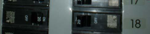
18 Figure 10. DNB 480V/380V Fused Disconnect for Control Power/ Aux Power Supplies. Located on Top Level, South wall, West side adjacent to DNB Rack #N5.

19 DNB Rack #N3 DNB Rack #N1 DNB Rack #5 DNB Rack #N2 contains power supply equipment for the HVPS and provide a pushbutton contactor control and Emergency Stop Button. Phase power on indicators are provided. DNB Rack #N5 houses the Arc Power Supply Breaker, Aux. Power Supply Breaker, 3 Grid Power Supply Breaker and BMPS breaker. All front and rear doors must be closed and locked for normal operation. Figure 11. DNB Racks # N3-N1 and N5 Located on Bottom Level, South wall

20 Input Service Caution - 380/220 VAC control power! Figure 12. DNB CAMAC Rack #N4. Rack houses CAMAC Controls, Digitizers and Instrumentation. 380VAC service is from 380/220VAC Fused Disconnect via Rack #N5 terminal blocks.


21 DNB PLC Rack with PLC, Gauges, gauge controllers and pump controllers. 120VAC Circuits inside. (See Fig. 17, also.) DNB Power Inductor. Covers must be in place for normal operation. Figure 13. DNB Power Inductor connects to circuits in Rack #N2 Located on Bottom Level, South wall of C-Mod Cell. Blue Rack adjacent to inductor houses DNB PLC and Controls


22 DNB Rack #N6 DNB Rack #N7 Doors are to remain closed and locked at all times except during maintenance or troubleshooting, when all safety procedures must be followed. Figure 14. DNB Racks #N6 and N7 located on Top Level, West of DNB in C-Mod Cell. These racks house power supply equipment referenced to the DNB 50kV Power Supply.
23 DNB High Voltage Cabling Referenced to High Voltage Power Supply DNB Arc-Discharge Plasma Box DNB High Voltage Cable From High Voltage Supply (Blue Tank above DNB) to Rack # N6 and N7. DNB HV Snubber Tank All Equipment covers must be in place for normal operation. During maintenance or troubleshooting all safety procedures must be followed. Figure 15. DNB HV Snubber Tank and Arc-Discharge Plasma Box house power supply equipment and cabling referenced to the DNB 50kV Power Supply.


24 Figure 16. DNB HV 50kV Power Supply (Blue Tank). Tank is filled with SF 6 Insulating Gas.


25 Input Service to DNB PLC Controls 120VAC, F Port Power Panel Ckt. 17. DNB PLC Controls Rack adjacent to DNB Rack #N3 on lower level South wall. Figure 17. DNB PLC Controls Rack (Blue) and its 120V Service Panel
Circuit Breakers,Reclosers, Switches, and Fuses
 Section 17 Circuit Breakers,Reclosers, Switches, and Fuses 170. ARRANGEMENT This rule requires circuit breakers, reclosers, switches, and fuses be accessible only to qualified persons. Section 17 is part
HydroGuard 4 to 20 ma Output Module. For use with HydroGuard Water Quality Monitor and Controller
 HydroGuard 4 to 20 ma Output Module For use with HydroGuard Water Quality Monitor and Controller Technician's Manual Installation, Operation, and Maintenance Guide Chapter 1: Preface... 3 1.1 Intended
SIEMENS HEALTHCARE INTEGRATED ELECTRICAL CABINET
 Product Data Sheet Technical Publications SIEMENS HEALTHCARE INTEGRATED ELECTRICAL CABINET for ARTIS Q / Q.ZEN / ZEE BIPLANE IECAX480V225A Main Disconnect Panel Bevco Engineering Company, Inc. CONFIDENTIAL
Installation, Operation, and Service Manual SIEMENS HEALTHCARE INTEGRATED ELECTRICAL CABINET
 Technical Publications SIEMENS HEALTHCARE INTEGRATED ELECTRICAL CABINET for ARTIS Q / Q.ZEN / ONE ARTIS ZEEGO / ZEEGO.ZEN ARTIS ZEE MULTIPURPOSE SINGLE PLANE IECAX480V125A Main Disconnect Panel Bevco Engineering
Quick Start Guide TS A
 Quick Start Guide TS 930 125-630A DANGER HAZARD OF ELECTRICAL SHOCK, EXPLOSION, OR ARC FLASH Read and understand this quick start guide before installing and operating the transfer switch The installer
Spending too much to maintain aging switchgear? Circuit breaker solutions from Square D Services.
 Spending too much to maintain aging switchgear? Circuit breaker solutions from Square D Services. Spending too much time and money on equipment maintenance? Square D Services: Your source for circuit breaker
SAVE THESE INSTRUCTIONS
 READ AND FOLLOW ALL SAFETY INSTRUCTIONS! SAVE THESE INSTRUCTIONS AND DELIVER TO OWNER AFTER INSTALLATION IMPORTANT SAFEGUARDS! When using electrical equipment, basic safety precautions should always be
INSTALLATION INSTRUCTIONS
 TM REPLACEMENT PARTS FOR USE WITH CX SERIES PANELS INSTALLATION INSTRUCTIONS Hubbell Control Solutions 9601 Dessau Road Building One Suite 100 Austin, TX 78754 Toll Free: 888-698-3242 Fax: 512-450-1215
When any of the following symbols appear, read the associated information carefully. Symbol Meaning Description
 Uni-I/O Modules Installation Guide UID-0808R, UID-0808T, UID-1600,UID-0016R, UID-0016T Uni-I/O is a family of Input/Output modules that are compatible with the UniStream control platform. This guide provides
LV MCC with Arc Flash Mitigation (AFM) Units
 Units") LV MCC with Arc Flash Mitigation (AFM) Units Technical Tuesday June 30, 2015 Imagination at work. Markets Oil and Gas Petro-Chemical Mining and metals Pulp and paper Mass-production manufacturing Water
LV MCC with Arc Flash Mitigation (AFM) Units Technical Tuesday June 30, 2015 Imagination at work. Markets Oil and Gas Petro-Chemical Mining and metals Pulp and paper Mass-production manufacturing Water
Test Asset Optimization Services Power Line Utilization Module (PLUM) DATA SHEET
 DATA SHEET") Test Asset Optimization Services Power Line Utilization Module (PLUM) DATA SHEET Description A Power Line Utilization Module (PLUM) is a device used to monitor the utilization and health parameters of
Test Asset Optimization Services Power Line Utilization Module (PLUM) DATA SHEET Description A Power Line Utilization Module (PLUM) is a device used to monitor the utilization and health parameters of
When any of the following symbols appear, read the associated information carefully. Symbol Meaning Description
 Uni-I/O Wide Modules Installation Guide UID-W1616R, UID-W1616T Uni-I/O Wide is a family of Input/Output modules that are compatible with the UniStream control platform. Wide Modules are 1.5 times as wide
When any of the following symbols appear, read the associated information carefully. Symbol Meaning Description
 Uni-I/O Modules Installation Guide UIA-0402N Uni-I/O is a family of Input/Output modules that are compatible with the UniStream control platform. This guide provides basic installation information for
SPECIAL INSTRUCTIONS FOR CAPACITORS COMPACT GENERATORS
 SPECIAL INSTRUCTIONS FOR CAPACITORS COMPACT GENERATORS (WITH CAPACITOR CHARGER BOARD A3517-02) The process depends on Generator and System configuration. This document applies to installation of Capacitors
This 4200-RM Rack Mount Kit is for installation in 4200-CAB series cabinets only.
 Keithley Instruments, Inc. 28775 Aurora Road Cleveland, Ohio 44139 (440) 248-0400 Fax: (440) 248-6168 www.keithley.com Model 4200-RM Rack Mount Kit Packing List Introduction NOTE This 4200-RM Rack Mount
ZC Series Zone Monitoring Controllers
 ZC Series Zone Monitoring Controllers Installation Instructions MANUAL Reset Controllers Model Description Part Number ZC-1 1 Zone Controller 0421 ZC-2 2 Zone Controller 0422 ZC-3 3 Zone Controller 0423
When any of the following symbols appear, read the associated information carefully. Symbol Meaning Description
 Uni-I/O Modules Installation Guide UID-0808THS Uni-I/O is a family of Input/Output modules that are compatible with the UniStream control platform. This guide provides basic installation information for
OPERATING MANUAL FOR THE 30KV A.C. TEST SET P123. Bicotest High Voltage Products Ltd
 OPERATING MANUAL FOR THE 30KV A.C. TEST SET P123 Product: High Voltage AC Test Set Type: P123 Bicotest High Voltage Products Ltd Hellesdon Park Road, Drayton High Road, Norwich NR6 5DR United Kingdom Phone
Replacing a Precision Controller Circuit Board
 Instruction heet Replacing a Precision Controller Circuit Board WARNING: Allow only qualified personnel to perform the following tasks. Observe and follow the safety instructions in this document and all
Technical Specifications. Multi Function Meter
 Technical Specifications of Multi Function Meter (SPM300) Class 0.5S Sai PowerrZerve 29/3B, Rajalakshmi Nagar, 1 st Main Road, Velachery Bye Pass, Chennai 600 042. Website :www.spowerz.com Email : info@spowerz.com
Rack Mount Power Supplies
 Rack Mount Power Supplies Installation Guide Models Include: VertiLine33D - 12VDC @ 8A - Sixteen (16) PTC protected outputs VertiLine33TD - 12VDC @ 16A - Sixteen (16) PTC protected outputs VertiLine63D
Model 8020-KHV. Kelvin Keithley Triaxial Connector Card. Description / October 2014 *P * 1
 Keithley Instruments 28775 Aurora Road Cleveland, Ohio 44139 1-800-935-5595 http://www.keithley.com Model 8020-KHV Kelvin Keithley Triaxial Connector Card Description The Model 8020-KHV Keithley HV Connector
Isolation of Electrical Energy Guidance
 Page 1 of 8 i ii Isolation of Electrical Energy Guidance 1. Scope 1.1. This document provides guidance on the various methods of isolation of electrical energy and highlights some (not all) of the limitations
HYPOT III. Quick Start Guide
 EN 61010-1 Quick Start Guide HYPOT III 3705, 3765, 3770, 3780 EN 61010-31 SAFETY CHECKLIST Survey the test station. Make sure it is safe & orderly. Always keep unqualified / unauthorized personnel away
Installation Instructions
 50ES, 50EZ, 50GL, 50GS, 50GX, 50JS, 50JX, 50JZ, 50SD, 50SZ, 50VL, 50VT, 50XP, 50XZ 601A, 602A, 602B, 604A, 604B, 604D, 607C, 701A, 702A, 702B, 704A, 704B, 704D, 707C PA1P, PA2P, PA3P, PH1P, PH2P, PH3P
2200 Series. Quick Start Guide SAFETY CHECKLIST. Safety Made Simple
 Safety Made Simple SAFETY CHECKLIST KEEP unqualified/unauthorized personnel away from the test area ARRANGE test stations in a safe and orderly manner NEVER touch products or connections during a test
USP-070-B08 USP-104-B10, USP-104-M10 USP-156-B10
 UniStream HMI Panel Installation Guide USP-070-B10, USP-070-B08 USP-104-B10, USP-104-M10 USP-156-B10 Unitronics UniStream platform comprises control devices that provide robust, flexible solutions for
Bulletin Installation of solar photovoltaic systems Rules , , , , and
 Bulletin 64-5-0 Installation of solar photovoltaic systems Rules 64-060, 64-200, 64-214, 84-020, 84-024 and 84-030 Scope (1) Introduction (2) Disconnecting means (a) Disconnecting means for solar photovoltaic
APPLICATION CONTROL GUIDELINES. IntelliROL Power Supply PN Revision Date: March 15, 2017
 APPLICATION CONTROL GUIDELINES IntelliROL Power Supply PN 1176718 Revision Date: March 15, 2017 Table of Contents List of Tables...3 TGW Safety Recommendation...4 Warnings and Safety Instructions...5 Introduction...6
Abstract. GLV User Manual 1
 GLV User Manual 1 Abstract This user manual is a high level document that explains all operational procedures and techniques needed to operate the GLV system in a safe and effective manner. Anyone operating
Model 2460-KIT. Screw Terminal Connector Kit. Description / September 2014 *P * 1
 Keithley Instruments 28775 Aurora Road Cleveland, Ohio 44139 1-800-935-5595 http://www.keithley.com Model 2460-KIT Screw Terminal Connector Kit Description The Model 2460-KIT Screw Terminal Connector Kit
Model 8020-STC. Kelvin Standard Triaxial Connector Card. Description / October 2014 *P * 1
 Keithley Instruments 28775 Aurora Road Cleveland, Ohio 44139 1-800-935-5595 http://www.keithley.com Model 8020-STC Kelvin Standard Triaxial Connector Card Description The Model 8020-STC Kelvin Standard
EMMS-T A00 SIERS. Siemens integrated electrical racking system instruction manual. usa.siemens.com/mvswitchgear
 EMMS-T40013-01-4A00 SIERS Siemens integrated electrical racking system instruction manual usa.siemens.com/mvswitchgear SIERS Siemens Integrated Electrical Racking System Instruction Manual Hazardous voltages
Power Control Systems
 Power Control Systems Power Control Systems for Virtually Any Control Strategy Power Control Systems for: Emergency generator control Emergency generator control with load demand sensing Emergency generator
SWITCHYARD SYSTEM BC1-SS-11-SD TRAINING SYSTEM DESCRIPTION NRG ENERGY, INC. BIG CAJUN 1
 SWITCHYARD SYSTEM TRAINING SYSTEM DESCRIPTION NRG ENERGY, INC. BIG CAJUN 1 November 2011 PREFACE This Training System Description has been designed to assist you in meeting the requirements of Module BC1-SS-11
Expandable Power Systems
 Expandable Power Systems Installation Guide Models Include: Maximal11EV 12VDC @ 4A or 24VDC @ 3A. 12VDC @ 4A or 24VDC @ 3A. Maximal33EV 12VDC or 24VDC @ 6A. 12VDC or 24VDC @ 6A. Maximal37EV 24VDC @ 10A.
HV-CS kv Edge Mount Triaxial Jack
 Keithley Instruments 28775 Aurora Road Cleveland, Ohio 44139 1-800-935-5595 http://www.tek.com/keithley HV-CS-1589 3 kv Edge Mount Triaxial Jack Installation Information Description The Keithley Instruments
Industries. Switchgear Interlock Applications. Process safety Control. Power Distribution Power Generation Power Transmission.
 Switchgear Interlock Applications Data Sheet Industries Power Distribution Power Generation Power Transmission Type DM Access Interlock with Spring Bolt Type PPS Interlock Quick-Trip ARC Flash Reduction
Installation Manual. APEX Series. Silicon and MOV Panel Protection. APEX Series
 Installation Manual APEX Series Silicon and MOV Panel Protection APEX Series APEX Series Installation Guide 2 Table of Contents Mechanical Installation 3 Table One - Application Rating 3 Figure 1 - Mounting
Power Supply Installation
 Power Supply Module Overview, on page Installation Guidelines, on page 4 Installing or Replacing an AC Power Supply, on page 6 Installing a DC Power Supply, on page 7 Finding the Power Supply Module Serial
UniStream HMI Panel. CPU-for-Panel
 UniStream HMI Panel Installation Guide USP-070-B10,USP-104-B10, USP-156-B10 Unitronics UniStream platform comprises control devices that provide robust, flexible solutions for industrial automation. This
EM-F-7G Safety Extension Module
 EM-F-7G Safety Extension Module One-channel control with four safety output channels Features Safety Extension Module provides additional safety outputs for a Primary Safety Device (for example, an E-stop
XBDM. 1015LV, 1020LV, 1030LV, 1020HV Models USER & INSTALLATION MANUAL BYPASS DISTRIBUTION MODULE
 XBDM 1015LV, 1020LV, 1030LV, 1020HV Models USER & INSTALLATION MANUAL www.xpcc.com 2013 Xtreme Power Conversion Corporation. All rights reserved. Table of Contents IMPORTANT SAFETY INSTRUCTIONS:... 4 INTRODUCTION...
Conext CL-60 Inverter Firmware Upgrade Process
 Conext CL-60 Inverter Firmware Upgrade Process http://solar.schneider-electric.com 976-0380-01-01/B August 2017 Application Note EXCLUSION FOR DOCUMENTATION UNLESS SPECIFICALLY AGREED TO IN WRITING, SELLER
ORB TM 4-20 ma Input Box Installation & Operation Manual
 IOM ORB TM 4-20 ma Input Box Installation & Operation Manual ORB TM 4-20 ma Input Box Installation & Operation Manual CONTENTS I. HANDLING & STORAGE... 1 Inspection and Handling Disposal and Recycling
QUICK SETUP GUIDE. BCM2 Series Branch Circuit Monitors. Safety Information. Equipment Maintenance and Service. Raritan DANGER!
 QUICK SETUP GUIDE BCM2 Series Branch Circuit Monitors Safety Information DANGER! HAZARD OF ELECTRIC SHOCK, EXPLOSION, OR ARC FLASH Follow safe electrical work practices. See NFPA 70E in the USA, or applicable
BCM2 Series Branch Circuit Monitors Quick Setup Guide
 BCM2 Series Branch Circuit Monitors Quick Setup Guide Safety Information DANGER! HAZARD OF ELECTRIC SHOCK, EXPLOSION, OR ARC FLASH Follow safe electrical work practices. See NFPA 70E in the USA, or applicable
Line reactors SINAMICS. SINAMICS G130 Line reactors. Safety information 1. General. Mechanical installation 3. Electrical installation
 Safety information 1 General 2 SINAMICS SINAMICS G130 Mechanical installation 3 Electrical installation 4 Technical specifications 5 Operating Instructions Control version V4.7 04/2014 A5E00331462A Legal
Starter and Circuit Breaker Application with PowerFlex 7000
 Application Technique Starter and Circuit Breaker Application with PowerFlex 7000 Bulletins 7000A, 7000, 7000L Topic Page General Precautions 2 Document Scope 2 Purpose 3 Drive Associated MV Starters and
Blue Box BLUE BOX TM LTD PARTS REPLACEMENT GUIDE
 Blue Box BLUE BOX TM LTD PARTS REPLACEMENT GUIDE WARNINGS 1. All servicing should be performed by qualified service personnel. 2. WARNING, Battery may explode if mistreated. Do not recharge, disassemble
Model 2657A-LIM-3 LO Interconnect Module
 Keithley Instruments, Inc. 28775 Aurora Road Cleveland, Ohio 44139 1-888-KEITHLEY http://www.keithley.com Model 2657A-LIM-3 LO Interconnect Module User's Guide Description The Model 2657A-LIM-3 LO Interconnect
Air-insulated medium-voltage secondary distribution switchgear
 DISTRIBUTION SOLUTIONS Air-insulated medium-voltage secondary distribution switchgear Compact size Complete solution Factory tested Air-insulated medium-voltage secondary distribution switchgear The ABB
120VAC Interface Option Cards for V7/ V74X / GPD315 Drives
 YASKAWA 120VAC Interface Option Cards for V7/ V74X / GPD315 Drives INSTRUCTIONS Upon receipt of the product and prior to initial operation, read these instructions thoroughly, and retain for future reference.
User and Installers Guide - Hardwired Maintenance Bypass Switches To Suit Eaton UPS
 Maintenance Bypass Switches 6M1004Rev 7 Issue Date: 20/04/2010. User and Installers Guide - Hardwired Maintenance Bypass Switches To Suit Eaton UPS www.eaton.com/powerquality 6M1004Rev7 Maintenance Bypass
LASERMET SLIMJIM LED SIGN INSTRUCTION MANUAL LEDS-SJ XXX
 LASERMET SLIMJIM LED SIGN INSTRUCTION MANUAL LEDS-SJ 00843-00-XXX 00843-53-000 Page 1 of 11 Issue 3 2 January 2013 Lasermet SlimJim Illuminated Sign Instruction Manual Contents Introduction... 4 Installation...
IEC H.P. Rated Pin and Sleeve Sequential contacts engagement during mating and un-mating IEC configurations specific to each voltage and
 IEC 60309 H.P. Rated Pin and Sleeve Sequential contacts engagement during mating and un-mating IEC configurations specific to each voltage and amperage to prevent interchangeability of voltages Watertight
When any of the following symbols appear, read the associated information carefully. Symbol Meaning Description
 Uni-I/O Modules Installation Guide UIS-04PTN Uni-I/O is a family of Input/Output modules that are compatible with the UniStream control platform. This guide provides basic installation information for
Active UTP Transceiver Hub with Integral Isolated Camera Power
 Active UTP Transceiver Hub with Integral Isolated Installation Guide HubWayEX16SP - UL Listed sixteen (16) Channel Active UTP Transceiver Hub with Integral Isolated Rev. 011810 More than just power. TM
User s Manual. ACS550-PD Stock 3R Irrigation Packaged Drive Supplement to ACS550-U1 User s Manual
 User s Manual ACS550-PD Stock 3R Irrigation Packaged Drive Supplement to ACS550-U1 User s Manual 2 ACS550-PD 3R Irrigation Packaged Drive ACS550 Drive Manuals GENERAL MANUALS ACS550-U1 User s Manual (1
OPERATIONS MANUAL. n.form I/O Expander (RACK MOUNT) Document Number: Rev B
 Document Number: Rev B") OPERATIONS MANUAL n.form I/O Expander (RACK MOUNT) Document Number: 200-0009 Rev B table of contents INTRODUCTION FEATURES & CAPABILITIES 1 WIRING General I/O Configuring The System Using The System 4
OPERATIONS MANUAL n.form I/O Expander (RACK MOUNT) Document Number: 200-0009 Rev B table of contents INTRODUCTION FEATURES & CAPABILITIES 1 WIRING General I/O Configuring The System Using The System 4
Small Power Station Surge Protection Analysis and Plan
 [Type the document title] Small Power Station Surge Protection Analysis and Plan By ArresterWorks Jonathan Woodworth ArresterWorks Page 1 Contents 1.0 Executive Summary... 3 1.1 Project Overview... 3 1.2
INSTRUCTION MANUAL. Universal AC Input Switching Power Supply 24 Vdc Output DIN-Rail Models PSD1000, PSD1000F PSD PSD1000F
 PSD1000 - PSD1000F INSTRUCTION MANUAL Universal AC Input Switching Power Supply 24 Vdc Output DIN-Rail Models PSD1000, PSD1000F PSD1000 - Universal AC Input Switching Power Supply 24 Vdc Output ISM0089-4
Source-Transfer Application Guide
 S&C Model 6802 Automatic Switch Control Source-Transfer Application Guide Table of Contents Section Page Section Page Introduction Qualified Persons.... 2 Read this Instruction Sheet.... 2 Retain this
CVU-3K-KIT. 3 kv Bias Tee Kit. Description. Parts list / October 2014 *P * 1
 Keithley Instruments 28775 Aurora Road Cleveland, Ohio 44139 1-800-935-5595 http://www.keithley.com CVU-3K-KIT 3 kv Bias Tee Kit Description The CVU-3K-KIT Bias Tee Kit consists of three bias tees for
Installation and Operations Manual INVOLAR MAC250 Microinverter
 Installation and Operations Manual INVOLAR MAC250 Microinverter Contact Information INVOLAR Corporation, Ltd. 887 Zuchongzhi Road, Build 84, Room 408, Shanghai, China 201203 Tel: 86-21-50272208 Fax: 86-21-50277705
SMART SHOT CONTROLLER FLUID USERS GUIDE
 SMART SHOT CONTROLLER FLUID USERS GUIDE Pg. 2 SMART SHOT CONTROLLER FEATURES 3 SMART SHOT CONTROLLER FEATURES 3 SMART SHOT CONTROLLER CONFIGURATIONS 4 FLOAT/SENSOR WIRING 5 TOP AND BOTTOM FLOAT/SENSOR
FC 1800 #1 Operation Manual University of Notre Dame
 \ FC 1800 #1 Operation Manual University of Notre Dame For Training Please contact: Dave Heemstra 8 June 2015 Page 1 of 12 General Precautions Contacts For problems, clarification of procedures, or general
External level devices for conductive point level switch
 SENSORS FOR FOOD AND BIOPHARMA. Product Information VNV-2, ZNV-2 CONTROLS External level devices for conductive point level switch Application/Specified usage Point level detection of aqueous, conductive
PV Rapid Shutdown device
 PV Rapid Shutdown device Installation and Operation Manual Solis-RSD-1G(1:1) Solis-RSD-1G(2:2) Manufacturer: Ginlong (Ningbo) Technologies Co.,Ltd., Ningbo, Zhejiang, P.R.China US Office: 565 Metro Pl.
Control. Part B, Section 2. This section covers the following unit configurations. 3400V 3500V Voltage 1, 2, 3 Pump Piston (D, E, F, G)
") Part B, Section 2 Model This section covers the following unit configurations. 3100V 3400V 3500V Voltage 1, 2, 3 Pump Piston (D, E, F, G) Manifold 4-Port (A) 6-Port (B or C) 2-Port (S or T) Vista Temperature
Part B, Section 2 Model This section covers the following unit configurations. 3100V 3400V 3500V Voltage 1, 2, 3 Pump Piston (D, E, F, G) Manifold 4-Port (A) 6-Port (B or C) 2-Port (S or T) Vista Temperature
ATS-16 HV USER MANUAL. Automatic Transfer Switch 16A / 230Vac V090318
 ATS-16 HV Automatic Transfer Switch 16A / 230Vac USER MANUAL V090318 SAFETY Intended use The ATS-16 HV device serves as a power source selector to provide improved power supply for connected loads. ATS-16
Revolutionizing control wiring
 SmartWire-DT Panel Wiring Solutions Revolutionizing control wiring 797-6925 Fax: (215) 221-1201 www.royalelectric.com SmartWire-DT Changing the way panels are wired. Reduce cost throughout the value chain.
Wiring Best Practices
 Form Number F-2825 Issue Date Jan 3, 2018 Revision Date Jun 5, 2018 Wiring Best Practices Selecting, planning, and routing wires. Waterous Company 125 Hardman Avenue South South Saint Paul, MN 55075 (651)
PRODUCT. Battery Charger
 PRODUCT Battery Charger Model : BC 9080 Battery Charger The ICD Battery Charger is designed to supply required DC Voltage and Current to the connected load and recharge the Battery on boost charging over
MC-3 Master Control Unit
 MC-3 Master Control Unit Customer Product Manual Issued 4/03 For parts and technical support, call the Industrial Coating Systems Customer Support Center at (800) 433-939 or contact your local Nordson
374 FC/375 FC/376 FC. Clamp Meter. Safety Information
 374 FC/375 FC/376 FC Clamp Meter Safety Information 3-Year Limited Warranty. Go to www.fluke.com to register your Product, read the Users Manual, and find more information. A Warning identifies conditions
Technical Specificaions. kwh Energy Meter
 Technical Specificaions of kwh Energy Meter (SPK301) Class 1.0S Sai PowerrZerve 29/3B, Rajalakshmi Nagar, 1 st Main Road, Velachery Bye Pass, Chennai 600 042. Website :www.spowerz.com Email : info@spowerz.com
SmartVFD Disconnect Panel Assemblies
 SmartVFD Panel Assemblies INSTALLATION INSTRUCTIONS APPLICATION Only The SmartVFD Panel Assemblies channel electrical power either through or around the variable frequency drive (VFD). INSTALLATION When
QUINT-BUFFER/24DC/24DC/40
 Buffer module Data sheet 105496_en_01 PHOENIX CONTACT 2013-11-01 1 Description The QUINT BUFFER buffer module combines the electronic switchover unit and power storage in the same housing. The buffer module
The power behind competitiveness. Delta Infrasuite Power Management. Power Distribution Unit. User Manual.
 The power behind competitiveness Delta Infrasuite Power Management Power Distribution Unit User Manual www.deltapowersolutions.com Save This Manual This manual contains important instructions and warnings
Installation Notes TII Model 341 Protector
 Installation Notes TII Model 341 Protector (ATT-IS PEC 32918) for MERLIN Communications System In Range Out of Building (IROB) Station Installation By Trained Technician Only WARNING: Failure to follow
ICTD-100CP / ICTD-101CP ICTD-102CP / ICTD-103CP
 PATENT PENDING ICTD-100CP / ICTD-101CP ICTD-102CP / ICTD-103CP Capacitor Trip Devices with Contact Protect Technology TM Operation Manual and Data sheet 2015 Intermountain Electronics, Inc. Important Notice
2260B-RMK-Series Rack Mount Kit
 Keithley Instruments, Inc. 28775 Aurora Road Cleveland, Ohio 44139 1-888-KEITHLEY http://www.keithley.com Assembly and Mounting Instructions Introduction The 2260B-RMK-Series Rack Mount Kit is suited for
Instruction Manual. M Pump Motor Controller. For file reference, please record the following data:
 Instruction Manual M Pump Motor Controller For file reference, please record the following data: Model No: Serial No: Installation Date: Installation Location: When ordering replacement parts for your
WBS HARDWIRED SERIES 4-60KVA MAINTENANCE BYPASS SWITCH
 WBS HARDWIRED SERIES 4-60KVA MAINTENANCE BYPASS SWITCH Man 440 Issue 7 1 1. INTRODUCTION... 3 2. INSTALLATION... 3 2.1 Connection of the Mains Supply... 3 2.2 Connection of the Input to the UPS... 4 2.3
SPECIFICATIONS NB SKILLS PROVINCIAL COMPETITION AUTOMATION AND CONTROL APRIL 20, 2018-NBCC MONCTON LE 20 AVRIL-NBCC MONCTON
 NB Provincial Skills Competition Industrial Control (formerly called Automation & Control) SPECIFICATIONS NB SKILLS PROVINCIAL COMPETITION AUTOMATION AND CONTROL APRIL 20, 2018-NBCC MONCTON LE 20 AVRIL-NBCC
White Paper. UL Standards for Power Control System Equipment
 White Paper UL Standards for Power Control System Equipment UL Standards for Power Control System Equipment An Introduction to UL 891 and UL 1558 Commercially available Power Controls Systems (PCS) can
Power Supply and Fan Module Installation
 3 CHAPTER This chapter describes how to remove and install a new or replacement power supply or fan module in a Catalyst 3750-E or Catalyst 3560-E switch. See these sections: Installation Overview, page
MEDIUM VOLTAGE PRODUCTS. UniSec Air-insulated medium voltage secondary distribution switchgear Informed choice for safety
 MEDIUM VOLTAGE PRODUCTS UniSec Air-insulated medium voltage secondary distribution switchgear Informed choice for safety 2 UNISEC AIR-INSULATED MEDIUM VOLTAGE SECONDARY DISTRIBUTION SWITCHGEAR Operator
Avanti HP Series Centrifuges Preinstallation
 J3HP-TB-001AC May 2009 Avanti HP Series Centrifuges Preinstallation INTRODUCTION Purchase of an Avanti HP series high performance centrifuge includes installation and Basic Instrument Training for two
L1.2 & L2.2. LED Studio Light OPERATING INSTRUCTIONS
 L1.2 & L2.2 LED Studio Light OPERATING INSTRUCTIONS 580 MAYER STREET, BUILDING #7, PA 15017 USA PHONE 1.412.206.0106 WWW.BRIGHTLINES.COM 2016 BRIGHTLINE, L.P. Safety WARNING: To avoid possible damage to
Solution Mining. tgood.com
 Solution Mining tgood.com TGOOD Introduction TGOOD is the global leader in prefabricated electric power distribution solutions. It is the company that first comes to mind when cost-effective electric power
Tunnelling SoluTionS
 Tunnelling Solutions Connecting YOU TO WORLD-CLASS electrical TUNNELLING SOLUTIONS Ampcontrol designs, manufactures and delivers cost effective and integrated electrical solutions for tunnelling and infrastructure
Installation Instructions
 Installation Instructions (Catalog Number 1771-OD) This document provides information on: Because of the variety of uses for the products described in this publication, those responsible for the application
DPM Active Harmonic Filter Quick Start Instructions
 DPM Active Harmonic Filter Quick Start Instructions These instructions will guide you through installing, testing your installation, and starting up your DPM. For additional information please refer to
VCM Systems Vehicle Control Module Systems
 VCM Systems Vehicle Control Module Systems Technical Manual VCMS-SC (Standard Configuration) Switch Panel System The Model VCMS-SC Switch Panel System is a standard configuration of the VCMS product family
PC-200-LLC-GM INSTALLATION INSTRUCTIONS. Revision A1 Rapid City, SD, USA, 10/2009 II_PC-XXX-LLC-GM_A1
 INSTALLATION INSTRUCTIONS Revision A1 Rapid City, SD, USA, 10/2009 MODELS PC-100-LLC-GM PC-200-LLC-GM II_PC-XXX-LLC-GM_A1 2880 North Plaza Drive, Rapid City, South Dakota 57702 (800) 843-8848 (605) 348-5580
Technical Specifications. Dual Source Energy Meter (EB / DG)
") Technical Specifications of Dual Source Energy Meter (EB / DG) (SPMG300) Class 0.5S Sai PowerrZerve 29/3B, Rajalakshmi Nagar, 1 st Main Road, Velachery Bye Pass, Chennai 600 042. Website :www.spowerz.com
Technical Specifications of Dual Source Energy Meter (EB / DG) (SPMG300) Class 0.5S Sai PowerrZerve 29/3B, Rajalakshmi Nagar, 1 st Main Road, Velachery Bye Pass, Chennai 600 042. Website :www.spowerz.com
Specifications, Installation, and Operating Instructions
 Specifications, Installation, and Operating Instructions Model: Power Vantage AC Panel Protector CAUTION: The installation of a surge protection device () must be done by qualified electrical personnel.
Hypot III. Graphic Liquid Crystal Display. 10 Memories with 3 Steps per Memory. Low Limit Detection System. SmartGFI Circuit (Patent Pending)
") Hypot III DIELECTRIC WITHSTAND TESTERS For Production Line Safety Agency Compliance Testing Graphic Liquid Crystal Display 10 Memories with 3 Steps per Memory Low Limit Detection System 3605 AC Hipot SmartGFI
Hypot III DIELECTRIC WITHSTAND TESTERS For Production Line Safety Agency Compliance Testing Graphic Liquid Crystal Display 10 Memories with 3 Steps per Memory Low Limit Detection System 3605 AC Hipot SmartGFI