Infrared Sensor with Laser Aiming. Operators manual thermometer CTL/CTLF/CTLG/CTLM-1/CTLM-2/CTLM-3
|
|
|
- Leon Riley
- 5 years ago
- Views:
Transcription

1 Infrared Sensor with Laser Aiming Operators manual thermometer CTL/CTLF/CTLG/CTLM-1/CTLM-2/CTLM-3
2 CE-Conformity The product complies with the following standards: EMC: EN Safety Regulations: EN :1993/ A2:1995 The product accomplishes the requirements of the EMC Directive 2004/108/EC Read the manual carefully before the initial start-up. The producer reserves the right to change the herein described specifications in case of technical advance of the product. Warranty All components of the device have been checked and tested for perfect function in the factory. In the unlikely event that errors should occur despite our thorough quality control, this should be reported immediately to MICRO-EPSILON. The warranty period lasts 12 months following the day of shipment. Defective parts, except wear parts, will be repaired or replaced free of charge within this period if you return the device free of cost to MICRO-EPSILON. This warranty does not apply to damage resulting from abuse of the equipment and devices, from forceful handling or installation of the devices or from repair or modifications performed by third parties. No other claims, except as warranted, are accepted. The terms of the purchasing contract apply in full. MICRO- EPSILON will specifically not be responsible for eventual consequential damages. MICRO-EPSILON always strives to supply the customers with the finest and most advanced equipment. Development and refinement is therefore performed continuously and the right to design changes without prior notice is accordingly reserved. For translations in other languages, the data and statements in the German language operation manual are to be taken as authoritative.
3 Content 1 Description Scope of Supply Maintenance Cautions Model Overview Factory Default Settings Technical Data General Specifications Electrical Specifications Measurement Specifications [CTL, CTL F] Measurement Specifications [M-1/ M-2 models] Measurement Specifications [M-3 models] Measurement Specifications [G models] Optical Charts Mechanical Installation Mounting Accessories Air Purge Collar Mounting Bracket Water Cooled Housing Electrical Installation Cable Connections Power Supply...39
4 10.3 Cable Assembling Ground Connection Exchange of the Sensor Entering of the Calibration Code Exchange of the Sensor Cable Outputs and Inputs Analog Outputs Output Channel Output Channel 2 [only for CTL, CTLF, G] Digital Interfaces USB Interface Kit Scope of Supply Installation RS232 Interface Kit Scope of Supply Installation RS485 Interface Kit Scope of Supply Installation CAN Bus Interface Profibus-Accessory-Kit Scope of Supply Installation... 55
5 Commissioning Profibus Ethernet-interface Scope of Supply Installation Installation of the CT Ethernet Adapter in a Network Uninstall the CT Ethernet Adapter in a Network Relay Outputs...62 Functional Inputs Alarms Output Channel 1 and Visual Alarms Operating Sensor Setup Set Factory Defaults Emissivity, Statistic, Prescriptive Limits Digital Command Set Laser Sighting Error Messages Software Installation System Requirements...73 Features Basics of Infrared Thermometry Emissivity... 76
6 15.1 Definition Determination of Unknown Emissivity Characteristic Emissivity...78 Appendix A Emissivity Table Metals Appendix B Emissivity Table Non Metals... 81
7 Description 1 Description The sensors of the CTL series are noncontact infrared temperature sensors. They calculate the surface temperature based on the emitted infrared energy of objects [ Basics of Infrared Thermometry]. An integrated double laser aiming marks the real measurement spot location and spot size at any distance on the object surface. The sensor housing of the CTL sensor is made of stainless steel (IP 65/ NEMA-4 rating) the sensor electronics is placed in a separate box made of die casting zinc. The CTL sensor is a sensitive optical system. Please use only the thread for mechanical installation. Avoid mechanical violence on the sensor this may destroy the system (expiry of warranty). 1.1 Scope of Supply CTL sensor with connection cable and controller Mounting nut and mounting bracket (fixed) Operators manual thermometer CTL/CTLF/CTLG/CTLM-1/CTLM-2/CTLM-3 7
8 Description 1.2 Maintenance Lens cleaning: Blow off loose particles using clean compressed air. The lens surface can be cleaned with a soft, humid tissue moistened with water or a water based glass cleaner. PLEASE NOTE: Never use cleaning compounds which contain solvents (neither for the lens nor for the housing). 1.3 Cautions Avoid static electricity, arc welders, and induction heaters. Keep away from very strong EMF (electromagnetic fields). Avoid abrupt changes of the ambient temperature. In case of problems or questions which may arise when you use the CTL, please contact our service department. thermometer CTL/CTLF/CTLG/CTLM-1/CTLM-2/CTLM-3 8
9 Description 1.4 Model Overview The sensors of the CTL series are available in the following basic versions: Model Measurement range Spectral response Typical applications CTL -50 to 975 C 8-14 μm non-metallic surfaces CTLF -50 to 975 C 8-14 μm fast processes CTLM to 1800 C 1 μm metals and ceramic surfaces CTLM to 1600 C 1.6 μm metals and ceramic surfaces CTLM-3 50 to 600 C 2.3 μm metals and composite materials CTLG 100 to 1650 C 5.2 μm measurement of glass On the CTLM-1, CTLM-2, CTLM-3 and CTLG models the whole measurement range is split into two sub ranges (L and H). thermometer CTL/CTLF/CTLG/CTLM-1/CTLM-2/CTLM-3 9
10 Description CTL/CTLF M-1L M-1H M-2L M-2H M-3L M-3H GL GH Lower limit temperature range [ C] Upper limit temperature range [ C] Lower alarm limit [ C] (normally closed) Upper alarm limit [ C] (normally open) Lower limit signal output 0 V Upper limit signal output 5 V Temperature unit C Ambient temperature compensation sensor temperature probe (output at OUT-AMB: 0-5 V C; not available on 1M and 2M models) Baud rate [kbaud] CTL: 9.6 / M-xL, M-xH: 115/ CTLG: 9.6 Laser inactive thermometer CTL/CTLF/CTLG/CTLM-1/CTLM-2/CTLM-3 10
11 Description 1.5 Factory Default Settings The unit has the following presetting at time of delivery: Signal output object temperature 0 5 V Emissivity (1.000 at CTLM) Transmissivity Average time (AVG) 0.2 s/ CTLF: 0.1 s/ M-1, M-2, M-3: inactive Smart Averaging inactive (CTLF: M1, M2, M3 active) Peak hold inactive Valley hold inactive Smart Averaging means a dynamic average adaptation at high signal edges. [Activation via software only]. thermometer CTL/CTLF/CTLG/CTLM-1/CTLM-2/CTLM-3 11
12 Technical Data 2 Technical Data 2.1 General Specifications Sensor Controller Environmental rating IP 65 (NEMA-4) IP 65 (NEMA-4 Ambient temperature 1) C C Storage temperature C C Relative humidity %, non condensing %, non condensing Material stainless steel die casting zinc Dimensions 100 mm x 50 mm, M48x1,5 89 mm x 70 mm x 30 mm Weight 600 g 420 g Cable length 3 m (Standard), 8 m, 15 m Cable diameter 5 mm Ambient temperature cable 105 C max. [High temperature cable (optional): 180 C] Vibration IEC : 3G, Hz, any axis Shock IEC : 50G, 11 ms, any axis EMC 2004/108/EC Tab. 2.1: General specifications 1) Laser will turn off automatically at ambient temperatures > 50 C. thermometer CTL/CTLF/CTLG/CTLM-1/CTLM-2/CTLM-3 12
13 Technical Data 2.2 Electrical Specifications Power Supply Current draw Aiming laser Outputs/ analog Channel 1 Channel 2 (L/ LF/ G5) Alarm output Output impedances ma mv Thermocouple Digital interfaces Relay outputs Functional inputs Tab. 2.2: Electrical specifications 8 36 VDC max. 160 ma 635 nm, 1 mw, On/ Off via programming keys or software selectable: 0/ 4 20 ma, 0 5/ 10 V, thermocouple (J or K) or alarm output (Signal source: object temperature) Sensor temperature [ C] as 0 5 V or 0 10 V output or alarm output (Signal source switchable to object temperature or controller temperature if used as alarm output) Open collector output at Pin AL2 [24 V/ 50 ma] max. loop resistance 500 Ω (at 8-36 VDC), min. 100 KΩ load impedance 20 Ω USB, RS232, RS485, CAN, Profibus DP, Ethernet (optional plug-in modules) 2 x 60 VDC/ 42 VAC RMS, 0.4 A; optically isolated (optional plug-in module) F1-F3; software programmable for the following functions: external emissivity adjustment, ambient temperature compensation, trigger (reset of hold functions) thermometer CTL/CTLF/CTLG/CTLM-1/CTLM-2/CTLM-3 13
14 Measurement Specifications [CTL, CTL F] 3 Measurement Specifications [CTL, CTL F] CTL CTLF Temperature range (scalable) C C Spectral range μm μm Optical resolution 75:1 50:1 System accuracy 1) 2) ±1 C or ±1 % 3) ±1.5 C or ±1.5 % 4) Repeatability 1) 2) ±0.5 C or ±0,5 % 3) ±1 C or ±1 % 4) Temperature resolution (NETD) 0.1 C 3) 0.5 C 4) Response time (90 % signal) 120 ms 9 ms Warm-up time 10 min 10 min Emissivity/ Gain (adjustable via programming keys or software) Transmissivity (adjustable via programming keys or software) Signal processing Average, peak hold, valley hold (adjustable via programming keys or software) Software optional Tab. 3.1: Measurement specifications [CTL, CTL F] 1) at ambient temperature 23±5 C; whichever is greater 2) Accuracy for thermocouple output: ±2.5 C or ±1 % 3) at object temperatures >0 C 4) at object temperatures 20 C thermometer CTL/CTLF/CTLG/CTLM-1/CTLM-2/CTLM-3 14
15 Measurement Specifications [M-1/ M-2 models] 4 Measurement Specifications [M-1/ M-2 models] M-1L M-1H M-2L M-2H Temperature range (scalable) C C C C Spectral range 1 μm 1 μm 1.6 μm 1.6 μm Optical resolution 150:1 300:1 150:1 300:1 System accuracy 1) 2) ±(0.3 % of reading +2 C) 3) Repeatability 1) ±(0.1 % of reading +1 C) 3) Temperature resolution 3) M-xL: 0.1 C / M-xH: 0.2 C Exposure time (90 % signal) 1 ms 4) Emissivity/ Gain (adjustable via programming keys or software) Transmissivity (adjustable via programming keys or software) Signal processing Average, peak hold, valley hold (adjustable via programming keys or software Software optional Tab. 4.1: Measurement specifications [M-1/ M-2 models] 1) at ambient temperature 23±5 C; whichever is greater 2) Accuracy for thermocouple output: ±2.5 C or ±1 % 3) ε = 1/ Response time 1 s 4) with dynamic adaptation at low signal levels thermometer CTL/CTLF/CTLG/CTLM-1/CTLM-2/CTLM-3 15
16 Measurement Specifications [M-3 models] 5 Measurement Specifications [M-3 models] M-3L M-31H Temperature range (scalable) C C Spectral range 2.3 μm 2.3 μm Optical resolution 60:1 100:1 System accuracy 1) 2) ±(0.3 % of reading +2 C) 3) Repeatability 1) ±(0.1 % of reading +1 C) 3) Temperature resolution 3) 0,1 C 3) Exposure time (90 % signal) 1 ms 4) Emissivity/ Gain (adjustable via programming keys or software) Transmissivity (adjustable via programming keys or software) Signal processing Average, peak hold, valley hold (adjustable via programming keys or software Software optional Tab. 5.1: Measurement specifications [M-3 models] 1) at ambient temperature 23±5 C; whichever is greater 2) Accuracy for thermocouple output: ±2.5 C or ±1 % 3) ε = 1/ Response time 1 s 4) with dynamic adaptation at low signal levels thermometer CTL/CTLF/CTLG/CTLM-1/CTLM-2/CTLM-3 16
17 Measurement Specifications [G models] 6 Measurement Specifications [G models] GL GH Temperature range (scalable) C C Spectral range 5.2 μm 5.2 μm Optical resolution 45:1 70:1 Accuracy 1) 2) ±1 C or ±1 % ±1 C or ±1 % Repeatability 1) 2) ±0.5 C or ±0.5 % ±0.5 C or ±0.5 % Temperature resolution (NETD) 0.1 C 0.2 C Response time (90 % signal) 120 ms 80 ms Warm-up time 10 min Emissivity/ Gain (adjustable via programming keys or software) Transmissivity (adjustable via programming keys or software) Signal processing Average, peak hold, valley hold (adjustable via programming keys or software) Software optional Tab. 6.1: Measurement specifications [G models] 1) at ambient temperature 23±5 C; whichever is greater 2) Accuracy for thermocouple output: ±2.5 C or ±1 % thermometer CTL/CTLF/CTLG/CTLM-1/CTLM-2/CTLM-3 17
18 Optical Charts 7 Optical Charts The following optical charts show the diameter of the measuring spot in dependence on the distance between measuring object and sensor. The spot size refers to 90 % of the radiation energy. The distance is always measured from the front edge of the sensor. The size of the measuring object and the optical resolution of the infrared thermometer determine the maximum distance between sensor and measuring object. In order to prevent measuring errors the object should fill out the field of view of the optics completely. Consequently, the spot should at all times have at least the same size like the object or should be smaller than that. D = Distance from front of the sensor to the object S = Spot size thermometer CTL/CTLF/CTLG/CTLM-1/CTLM-2/CTLM-3 18
19 Optical Charts CTL Optik: SF D:S (Focus distance) = 75: mm D:S (Far field) = 34:1 CTL Optik: CF1 D:S (Focus distance) = 75: mm D:S (Far field) = 3,5:1 thermometer CTL/CTLF/CTLG/CTLM-1/CTLM-2/CTLM-3 19
20 Optical Charts CTL Optik: CF2 D:S (Focus distance) = 75: mm D:S (Far field) = 7:1 CTL Optik: CF3 D:S (Focus distance) = 75: mm D:S (Far field) = 9:1 thermometer CTL/CTLF/CTLG/CTLM-1/CTLM-2/CTLM-3 20
21 Optical Charts CTL Optik: CF4 D:S (Focus distance) = 75: mm D:S (Far field) = 18:1 CTLF Optik: SF D:S (Focus distance) = 50: mm D:S (Far field) = 20:1 thermometer CTL/CTLF/CTLG/CTLM-1/CTLM-2/CTLM-3 21
22 Optical Charts CTLF Optik: CF1 D:S (Focus distance) = 50: mm D:S (Far field) = 1,5:1 CTLF Optik: CF2 D:S (Focus distance) = 50: mm D:S (Far field) = 6:1 thermometer CTL/CTLF/CTLG/CTLM-1/CTLM-2/CTLM-3 22
23 Optical Charts CTLF Optik: CF3 D:S (Focus distance) = 50: mm D:S (Far field) = 8:1 CTLF Optik: CF4 D:S (Focus distance) = 50: mm D:S (Far field) = 16:1 thermometer CTL/CTLF/CTLG/CTLM-1/CTLM-2/CTLM-3 23
24 Optical Charts M-1H/ M-2H Optik: FF D:S (Focus distance) = 300: mm D:S (Far field) = 115:1 M-1L/ M-2L Optik: FF D:S (Focus distance) = 150: mm D:S (Far field) = 84:1 M-1H/ M-2H Optik: SF D:S (Focus distance) = 300:1 3.7 mm D:S (Far field) = 48:1 M-1L/ M-2L Optik: SF D:S (Focus distance) = 150: mm D:S (Far field) = 42:1 thermometer CTL/CTLF/CTLG/CTLM-1/CTLM-2/CTLM-3 24
25 Optical Charts M-1H/ M-2H Optik: CF2 D:S (Focus distance) = 300: mm D:S (Far field) = 7,5:1 M-1L/ M-2L Optik: CF2 D:S (Focus distance) = 150: mm D:S (Far field) = 7:1 M-1H/ M-2H Optik: CF3 D:S (Focus distance) = 300: mm D:S (Far field) = 10:1 M-1L/ M-2L Optik: CF3 D:S (Focus distance) = 150: mm D:S (Far field) = 10:1 thermometer CTL/CTLF/CTLG/CTLM-1/CTLM-2/CTLM-3 25
26 Optical Charts M-1H/ M-2H Optik: CF4 D:S (Focus distance) = 300: mm D:S (Far field) = 22:1 M-1L/ M-2L Optik: CF4 D:S (Focus distance) = 150: mm D:S (Far field) = 20:1 thermometer CTL/CTLF/CTLG/CTLM-1/CTLM-2/CTLM-3 26
27 Optical Charts M-3H Optik: CF1 D:S (Focus distance) = 100: mm D:S (Far field) = 3:1 M-3L Optik: CF1 D:S (Focus distance) = 60: mm D:S (Far field) = 3:1 M-3H Optik: CF2 D:S (Focus distance) = 100: mm D:S (Far field) = 7:1 M-3L Optik CF2 D:S (Focus distance) = 60: mm D:S (Far field) = 6:1 thermometer CTL/CTLF/CTLG/CTLM-1/CTLM-2/CTLM-3 27
28 Optical Charts M-3H Optik: CF3 D:S (Focus distance) = 100: mm D:S (Far field) = 9:1 M-3L Optik: CF3 D:S (Focus distance) = 60: mm D:S (Far field) = 8:1 M-3H Optik: CF4 D:S (Focus distance) = 100: mm D:S (Far field) = 19:1 M-3L Optik: CF4 D:S (Focus distance) = 60: mm D:S (Far field) = 17:1 thermometer CTL/CTLF/CTLG/CTLM-1/CTLM-2/CTLM-3 28
29 Optical Charts M-3H Optik: SF D:S (Focus distance) = 100: mm D:S (Far field) = 38:1 M-3L Optik: SF D:S (Focus distance) = 60: mm D:S (Far field) = 30:1 GL Optik: SF D:S (Focus distance) = 45: mm D:S (Far field) = 25:1 GH Optik: SF D:S (Focus distance) = 70: mm D:S (Far field) = 33:1 thermometer CTL/CTLF/CTLG/CTLM-1/CTLM-2/CTLM-3 29
30 Optical Charts GL Optik: CF1 D:S (Focus distance) = 45: mm D:S (Far field) = 3:1 GH Optik: CF1 D:S (Focus distance) = 70: mm D:S (Far field) = 3.4:1 GL Optik: CF2 D:S (Focus distance) = 45: mm D:S (Far field) = 6:1 GH Optik: CF2 D:S (Focus distance) = 70: mm D:S (Far field) = 6.8:1 thermometer CTL/CTLF/CTLG/CTLM-1/CTLM-2/CTLM-3 30
31 Optical Charts GL Optik: CF3 D:S (Focus distance) = 45: mm D:S (Far field) = 8:1 GH Optik: CF3 D:S (Focus distance) = 70: mm D:S (Far field) = 9.2:1 GL Optik: CF4 D:S (Focus distance) = 45: mm D:S (Far field) = 15:1 GH Optik: CF4 D:S (Focus distance) = 70: mm D:S (Far field) = 17.7:1 thermometer CTL/CTLF/CTLG/CTLM-1/CTLM-2/CTLM-3 31
 and fixed mounting bracket (standard) to a mounting device available. Fig. 8.")
32 Mechanical Installation 8 Mechanical Installation The CTL is equipped with a metric M48x1.5 thread and can be installed either directly via the sensor thread or with help of the supplied mounting nut (standard) and fixed mounting bracket (standard) to a mounting device available. Fig. 8.1: CTL sensor Make sure to keep the optical path clear of any objects. thermometer CTL/CTLF/CTLG/CTLM-1/CTLM-2/CTLM-3 32


![[ Operating/ Laser sighting]](/docs-images/84/90594973/images/33-2.jpg "thermometer")
33 Mechanical Installation Fig. 8.2: Controller For an exact alignment of the head to the object, please activate the integrated double laser. [ Operating/ Laser sighting] thermometer CTL/CTLF/CTLG/CTLM-1/CTLM-2/CTLM-3 33


34 Mechanical Installation Fig. 8.3: Mounting bracket, fixed standard scope of supply thermometer CTL/CTLF/CTLG/CTLM-1/CTLM-2/CTLM-3 34


35 Mounting Accessories 9 Mounting Accessories 9.1 Air Purge Collar The lens must be kept clean at all times from dust, smoke, fumes and other contaminants in order to avoid reading errors. These effects can be reduced by using an air purge collar. Make sure to use oil-free, technically clean air, only. Fig. 9.1: Air purge collar [TM-AP-CTL] The needed amount of air (approx l/ min.) depends on the application and the installation conditions on-site. thermometer CTL/CTLF/CTLG/CTLM-1/CTLM-2/CTLM-3 35


36 Mounting Accessories 9.2 Mounting Bracket Fig. 9.2: Mounting bracket, adjustable [TM-AB-CTL] The adjustable mounting bracket allows an adjustment of the sensor in two axis. thermometer CTL/CTLF/CTLG/CTLM-1/CTLM-2/CTLM-3 36
![Mounting Accessories 9.3 Water Cooled Housing Fig. 9.3: Water cooled housing [TM-W-CTL] To avoid condensation on the optics an air purge collar is recommended.](/docs-images/84/90594973/images/37-0.jpg "The sensor can be used at ambient temperatures up to 85 C without cooling.")
. The sensor should be equipped with the optional high temperature cable (operating temperature up to 180 C).")
37 Mounting Accessories 9.3 Water Cooled Housing Fig. 9.3: Water cooled housing [TM-W-CTL] To avoid condensation on the optics an air purge collar is recommended. The sensor can be used at ambient temperatures up to 85 C without cooling. For applications, where the ambient temperature can reach higher values, the usage of the optional water cooled housing is recommended (operating temperature up to 175 C). The sensor should be equipped with the optional high temperature cable (operating temperature up to 180 C). All accessories can be ordered using the according part numbers in brackets [ ]. thermometer CTL/CTLF/CTLG/CTLM-1/CTLM-2/CTLM-3 37
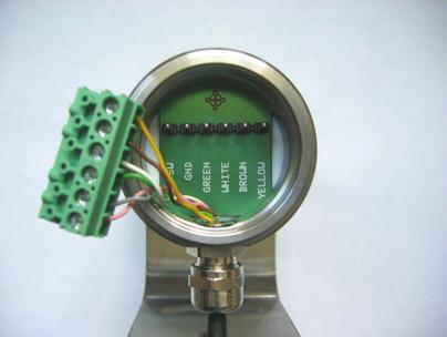
38 Electrical Installation 10 Electrical Installation 10.1 Cable Connections For the electrical installation of the CTL, please open at first the cover of the electronic box (4 screws). Below the display are the screw terminals for the cable connection VDC GND GND OUT-AMB OUT-TC OUT-mV/mA F1-F3 AL2 3V SW GND BROWN WHITE GREEN YELLOW Designation [models CTL/ CTLF/ G] Designation [models M] Power supply VDC Ground (0 V) of power supply GND Ground (0 V) of internal in- and outputs GND Analog output sensor temperature (mv) AL2 Analog output thermocouple (J or K) OUT-TC Analog output object temperature (mv or ma) OUT-mV/mA Functional inputs F1-F3 Alarm 2 (Open collector output) GND PINK/ Power supply Laser (+) LASER GREY/ Ground Laser ( ) GND Temperature probe sensor PWR Temperature probe sensor GND Detector signal ( ) NTC Detector signal (+) VV Power supply Ground (0 V) of power supply Ground (0 V) of internal in- and outputs Alarm 2 (Open collector output) Analog output thermocouple (J or K) Analog output object temperature (mv or ma) Functional inputs Ground (0 V) PINK/ Power supply Laser (+) GREY/ Ground Laser ( ) GREEN/ Sensor power WHITE/ Sensor ground BROWN/ Temperature probe sensor (NTC) YELLOW/ Detector signal thermometer CTL/CTLF/CTLG/CTLM-1/CTLM-2/CTLM-3 38


39 Electrical Installation Fig. 10.1: Opened electronic box with terminal connections 10.2 Power Supply Please use a power supply unit with an output voltage of 8 36 VDC which can supply 160 ma. CAUTION: Please do never connect a supply voltage to the analog outputs as this will destroy the output! The CTL is not a 2-wire sensor! thermometer CTL/CTLF/CTLG/CTLM-1/CTLM-2/CTLM-3 39
40 Electrical Installation 10.3 Cable Assembling The cable gland M12x1.5 allows the use of cables with a diameter of 3 to 5 mm. Remove the isolation from the cable (40 mm power supply, 50 mm signal outputs, 60 mm functional inputs). Cut the shield down to approximately 5 mm and spread the strands out. Extract about 4 mm of the wire isolation and tin the wire ends. Place the pressing screw, the rubber washer and the metal washers of the cable gland one after the other onto the prepared cable end. Spread the strands and fix the shield between two of the metal washers. Insert the cable into the cable gland until the limit stop. Screw the cap tight. Every single wire may be connected to the according screw clamps according to their colors. Fig. 10.2: Cable Assembling Use shielded cables only. The sensor shield has to be grounded. thermometer CTL/CTLF/CTLG/CTLM-1/CTLM-2/CTLM-3 40
 which has been placed from factory side as shown in the picture [left and middle pin connected].")
41 Electrical Installation 10.4 Ground Connection At the bottom side of the main board PCB you will find a connector (jumper) which has been placed from factory side as shown in the picture [left and middle pin connected]. In this position the ground connections (GND power supply/ outputs) are connected with the ground of the controller housing. To avoid ground loops and related signal interferences in industrial environments it might be necessary to interrupt this connection. To do this, please put the jumper in the other position [middle and right pin connected]. If the thermocouple output is used the connection GND housing should be interrupted generally. Fig. 10.3: Connector (Jumper) thermometer CTL/CTLF/CTLG/CTLM-1/CTLM-2/CTLM-3 41
42 Electrical Installation 10.5 Exchange of the Sensor From factory side the sensor has already been connected to the controller. Inside the model group CTL and inside the model group G an exchange of sensors and controllers is possible. The sensors and controllers of the models CTLF, M-1L, M-1H, M-2L, M-2H, M-3L, and M-3 H cannot be exchanged. After exchanging a sensor the calibration code of the new sensor must be entered into the controller Entering of the Calibration Code Every sensor has a specific calibration code, which is printed on the sensor. For a correct temperature measurement and functionality of the sensor this calibration code must be stored into the controller. The calibration code consists of five blocks with 4 characters each. Example: EKJ0 0OUD 0A1B A17U 93OZ block1 block2 block3 block4 block5 For entering the code, please press the Up and Down key (keep pressed) and then the Mode key. The display shows HCODE and then the 4 signs of the first block. With Up and Down each sign can be changed, Mode switches to the next sign or next block. thermometer CTL/CTLF/CTLG/CTLM-1/CTLM-2/CTLM-3 42

43 Electrical Installation Fig. 10.4: Calibration Code You will find the calibration code on a label fixed on the sensor. Please do not remove this label or make sure the code is noted anywhere. The code is needed if the sensor has to be exchanged Exchange of the Sensor Cable The sensor cable can also be exchanged if necessary. For a dismantling on the sensor side, please open at first the cover plate on the back side of the sensor. Then please remove the terminal block and loose the connections. After the new cable has been installed, please do the same steps in reverse order. Please take care the cable shield is properly connected to the sensor housing. As exchange cable a cable type with same wire profiles and specification should be used to avoid influences on the accuracy. thermometer CTL/CTLF/CTLG/CTLM-1/CTLM-2/CTLM-3 43

44 Electrical Installation Fig. 10.5: View on terminal block with sensor cables thermometer CTL/CTLF/CTLG/CTLM-1/CTLM-2/CTLM-3 44
45 Outputs and Inputs 11 Outputs and Inputs 11.1 Analog Outputs The CTL has two analog output channels Output Channel 1 This output is used for the object temperature. The selection of the output signal can be done via the programming keys [ Operating]. The software allows the programming of output channel 1 as an alarm output. Output signal Range Connection pin on CTL board Voltage V OUT-mV/mA Voltage V OUT-mV/mA Current ma OUT-mV/mA Current ma OUT-mV/mA Thermocouple TC J OUT-TC Thermocouple TC K OUT-TC According to the chosen output signal there are different connection pins on the main board (OUT-mV/mA or OUT-TC). thermometer CTL/CTLF/CTLG/CTLM-1/CTLM-2/CTLM-3 45
46 Outputs and Inputs Output Channel 2 [only for CTL, CTLF, G] The connection pin OUT AMB is used for output of the sensor temperature [ C as 0 5 V or 0 10 V signal]. The software allows the programming of output channel 2 as an alarm output. Instead of the sensor temperature THead also the object temperature TObj or controller temperature TBox can be selected as alarm source Digital Interfaces The controller can be optionally equipped with an USB-, RS232-, RS485-, CAN Bus-, Profibus DP- or Ethernet-interface. If you want to install an interface, plug the interface board into the place provided, which is located beside the display. In the correct position the holes of the interface match with the thread holes of the controller. Now press the board down to connect it and use both M3x5 screws for fixing it. Plug the preassembled interface cable with the terminal block into the male connector of the interface board. The Ethernet interface requires at minimum 12 V supply voltage. Please pay attention to the notes on the according interface manuals. thermometer CTL/CTLF/CTLG/CTLM-1/CTLM-2/CTLM-3 46
47 Outputs and Inputs Fig. 11.1: CTL controller with Interface board USB Interface Kit Scope of Supply USB interface board Software CD USB adapter cable Terminal block Cable gland Mounting screws and cable tie thermometer CTL/CTLF/CTLG/CTLM-1/CTLM-2/CTLM-3 47
48 Outputs and Inputs Installation Please plug the USB interface into the place provided, which is located beside the display. In the correct position the holes of the USB interface match with the thread holes of the controller. Now press the PCB downwards and fix it using both M3x5 screws. Exchange the blind screw on the controller by the cable gland and install the USB adapter cable. Make sure the wiring is correct according to the wire colors printed on the interface board. NOTE: For industrial installations it is recommended to connect the shield of the USB adapter cable with the controller housing (inside the cable gland). The CTL needs no external power supply for operation it will be powered by the USB interface. If an external power supply has already been installed, this will not affect functionality of the CTL. Fig. 11.2: CTL controller with USB Interface thermometer CTL/CTLF/CTLG/CTLM-1/CTLM-2/CTLM-3 48
49 Outputs and Inputs RS232 Interface Kit Scope of Supply 1 pcs. Package 1 pcs. Cable gland M12x1.5 1 pcs. Quick reference 1 pcs. RS232-Interface 1 pcs. Software CD 2 pcs. Screw M3x5 1 pcs. RS232-interface cable preassembled 1 pcs. Cable tie Installation Please take the RS232-interface out from the packaging and plug it into the place provided, which is located beside the display. In the correct position the holes of the RS232 interface match with the thread holes of the controller. Now press the RS232 interface down to connect it with the CTL. Use both M3x5 screws for fixing the interface. Plug the preassembled RS232-interface cable with the terminal block into the male connector of the RS232-interface. In the case that you want to use the delivered cable gland M12x1.5 for the RS232 cable, the terminal block has to be disassembled/ assembled. Make sure the wiring is correct. thermometer CTL/CTLF/CTLG/CTLM-1/CTLM-2/CTLM-3 49
50 Outputs and Inputs The CTL always needs an external power supply for operation. Please install the software CTL connect as described in the operators manual. After you have connected the RS232-cable to your PC and started the software the communication will be established. The setting for baud rate in the software must be the same as on the CTL unit (factory default: 9.6 kbaud). Fig. 11.3: Correct wiring RS485 Interface Kit Scope of Supply 1 pcs. Packaging 1 pcs. RS485-USB-Adapter 1 pcs. Quick reference 1 pcs. Cable gland M12x1.5 1 pcs. Software CD (CTconnect, CTmulti) 2 pcs. Screw M3x5 1 pcs. USB cable 1 pcs. Cable tie 1 pcs. RS485-interface 3 pcs. Terminal block on the board thermometer CTL/CTLF/CTLG/CTLM-1/CTLM-2/CTLM-3 50
51 Outputs and Inputs Installation Please connect the RS485-USB-adapter via the supplied USB cable with your computer. After it has been connected the computer will recognize a new USB-device and (if connected the first time) will ask for installation of the according driver software. Please select Search and install the RS485 Adapter USB Driver from the software CD. Please take the RS485-interface out from the packaging and plug it into the place provided, which is located beside the display. In the correct position the holes of the RS485 interface match with the thread holes of the controller. Now press the RS485-interface down to connect it with the CTL. Use both M3x5 screws for fixing the board. The RS485-USB-adapter TM-RS485USBK-CTL is providing a 2-wire half-duplex mode. Please connect terminal A of the adapter with terminal A of the RS485-interface of the first CTL and from there to terminal A of the next CTL and so on (Fig. 2). With the B terminals proceed as well. Make sure, that you always connect A to A and B to B, not reverse. You may run up to 32 CTL units on one RS485-USB-adapter. The 120R-switch is to be turned to ON at one of the connected CTL units, only. Each CTL unit connected to the RS485 needs a different multidrop address (1...32). Please adjust the address by pressing the mode button until M xx appears in the display. Using the Up- and Down-keys you can change the shown address (xx). The address can also be changed with the CTL connect software. The setting for baud rate in the software must be the same as on the CTL unit (factory default: 9.6 kbaud). thermometer CTL/CTLF/CTLG/CTLM-1/CTLM-2/CTLM-3 51
52 Outputs and Inputs USB cable ; Kabel OFF OFF OFF RS485 to USB adaptor RS485 zu USB Adapter RS485 Interface 120R RS485 Interface 120R RS485 Interface 20R ON ON ON B B A A B B A A B B A A B A PC 120R switch OFF 120R Schalter OFF Multidrop Adress 1 120R switch OFF 120R Schalter OFF Multidrop Adress n 120R switch ON 120R Schalter ON Multidrop Adress 32 Fig. 11.4: Correct wiring thermometer CTL/CTLF/CTLG/CTLM-1/CTLM-2/CTLM-3 52
 Wiring CAN Bus: CAN_H on terminal H CAN_L on terminal L Analog signal: Black cord on terminal GND Black cord on terminal OUT-mV The")
53 Outputs and Inputs CAN Bus Interface CAN Protocol CAN open (see documentation on CD) Wiring CAN Bus: CAN_H on terminal H CAN_L on terminal L Analog signal: Black cord on terminal GND Black cord on terminal OUT-mV The controller contains additional terminals to connect other devices (power supply, CAN bus, terminating resistor). CAN module settings Module address: 20 (14 H) Baud rate: 250 kbaud Analog input: 0 10 V Temperature range: 0 60 C (2 decimal places) Emission ratio: Note: The settings for Analog output 0 10 V and "Temperature range 0 60 C" must be identical with the CAN bus module values. thermometer CTL/CTLF/CTLG/CTLM-1/CTLM-2/CTLM-3 53
54 Outputs and Inputs Settings Address and Baud rate CAN open-service "LSS / Layer Setting Services" Index Temperature value: The temperature information is located in the object register 7130h (Sub01): B4: LB B5: HB e.g. B4: DA B5: 07 T = C Diagnosis If the power supply is on, the LED displays one of the following conditions: State Meaning Flashes quickly Device is in preoperational mode Off Power supply is not correct / faulty hardware Illuminates Device is in operational mode Sparkles Device is stopped thermometer CTL/CTLF/CTLG/CTLM-1/CTLM-2/CTLM-3 54
55 Outputs and Inputs Profibus-Accessory-Kit Scope of Supply 1 pcs. Packaging 1 pcs. Cable gland M12x1.5 1 pcs. Quick reference 1 pcs. Profibus-DPv1-interface 1 pcs. Software CD 2 pcs. Screws M3x5 1 pcs. Profibus-interface cable preassembled Installation Please take the Profibus-DPv1-interface out from the packaging and plug it into the place provided, which is located beside the display. In the correct position the holes of the Profibus-DPv1-interface match with the thread holes of the CT box. Now press the Profibus DPv1-interface down to connect it with the CT. Use both M3x5 screws for fixing the interface. Plug the preassembled Profibus-DPv1 interface cable with the terminal block into the male connector of the Profibus-DPv1-interface. In the case that you want to use the delivered cable gland M12x1.5 for the Profibus cable, the terminal block has to be disassembled/ assembled. Make sure the wiring is correct (Fig. 2). NOTE: For industrial installations it is recommended to connect the shield of the Profibus-cable with the controller housing (inside the cable gland). thermometer CTL/CTLF/CTLG/CTLM-1/CTLM-2/CTLM-3 55
56 Outputs and Inputs The CT always needs an external power supply for operation. Fig. 11.5: Correct wiring thermometer CTL/CTLF/CTLG/CTLM-1/CTLM-2/CTLM-3 56

57 Outputs and Inputs Commissioning Profibus 1. Read in the IT010A90.gsd GSD file into the PLC configuration tool and configure the controller. At least one module must be selected. You will find more information about the Profibus interface on the enclosed CD-ROM. 2. Open the controller and connect the power supply, see figure below. Profibus cable Power supply Sensor cable GND +8 up to +36 VDC thermometer CTL/CTLF/CTLG/CTLM-1/CTLM-2/CTLM-3 57
58 Outputs and Inputs 3. Switch on the power supply. 4. Press the Mode button 18 times until the item SL001 appears. Set the slave address with the UP and DOWN buttons. Valid slave addresses start with 001 up to 125. Use the same address as in the PLC configuration tool, see page 4 in the manual. 5. Switch off the controller for at least 3 seconds. 6. Connect the SUB-D connector of the Profibus cable with a Profibus port. Take care on the terminating resistor of the Profibus. 7. The controller with Profibus-DPv1 is now ready for data exchange with the Profibus master; see the manual on page The measurements are displayed in hex format and must be converted into decimals; see the manual on page The settings of the Profibus-DPv1 interface and the communication with the Profibus master are described in the manual on page 8 up to 31. thermometer CTL/CTLF/CTLG/CTLM-1/CTLM-2/CTLM-3 58
59 Outputs and Inputs Ethernet-interface Scope of Supply 1 pcs. Packaging 1 pcs. Cable gland M12x1.5 1 pcs. Quick reference 1 pcs. Ethernet-interface 1 pcs. Software CD 2 pcs. Screw M3x5 1 pcs. Ethernet-interface preassembled 1 pcs. Cable tie Installation Please take the Ethernet interface out from the packaging and plug it into the place provided, which is located beside the display. In the correct position the holes of the interface match with the thread holes of the CT box. Now press the interface down to connect it with the CT. Use both M3x5 screws for fixing the interface. Plug the interface box with the preassembled terminal block into the male connector of the Ethernet interface. In the case that you want to use the delivered cable gland M12x1.5 for the Ethernet box, the terminal block has to be disassembled/ assembled. The CT requires an external power supply in each case Installation of the CT Ethernet Adapter in a Network First install the driver software of the Ethernet adapter on the supplied CD (Compact Connect CD). To start the installation, start the file SETUP.EXE in the path: Driver/Ethernet. The following dialog appears: thermometer CTL/CTLF/CTLG/CTLM-1/CTLM-2/CTLM-3 59

60 Outputs and Inputs Fig. 11.6: CT Ethernet Com Port Installation Enter the MAC address of the adapter in the field MAC Address. You will find the address on the housing. Select in the pull-down menu COM PORT the desired COM port or FIRST POSSIBLE for the first available COM port. Now click on the button INSTALL COM PORT. Installation is completed, if the letters in the button are black again. The COM port is now set in the Device Manager and can be used from the software Compact Connect. You will find a manual for Installation and operation of the Compact Connect software on the CD. thermometer CTL/CTLF/CTLG/CTLM-1/CTLM-2/CTLM-3 60

61 Outputs and Inputs Uninstall the CT Ethernet Adapter in a Network To uninstall the driver software, start the file REMOVE.EXE on the supplied CD. The file is located in the path: Driver/Ethernet. The following dialog appears: The dialog allows you to permanently remove a single module or all modules from the system. To install the CT Ethernet adapter in a direct connection to a PC you will find more information in the path: Manuals\Interfaces on the Compact Connect CD. thermometer CTL/CTLF/CTLG/CTLM-1/CTLM-2/CTLM-3 61

62 Outputs and Inputs 11.3 Relay Outputs The CTL can be optionally equipped with a relay output. The relay board will be installed the same way as the digital interfaces. A simultaneous installation of a digital interface and the relay outputs is not possible. The relay board provides two fully isolated switches, which have the capability to switch max. 60 VDC/ 42 VAC RMS, 0.4 A DC/AC. A red LED shows the closed switch. The switching thresholds are in accordance with the values for alarm 1 and 2 [ Alarms/ Visual Alarms]. The alarm values are set according to the Factory Default Settings. The adjustment of the alarms can result from the modification of the alarm 1 and alarm 2 via the programming keys. To make advanced settings a digital interface (USB, RS232) and the software is needed. Fig. 11.7: Relais Interface with correct wiring thermometer CTL/CTLF/CTLG/CTLM-1/CTLM-2/CTLM-3 62
63 Outputs and Inputs 11.4 Functional Inputs The three functional inputs F1 F3 can be programmed with the software, only. F1 (digital): F2 (analog): F3 (analog): trigger (a 0 V level on F1 resets the hold functions) external emissivity adjustment [0 10 V: 0 V ε=0.1; 9 V ε=1; 10 V ε=1.1] external compensation of ambient temperature/ the range is scalable via software [0 10 V C / preset range: C] F1-F3 (digital): emissivity (digital choice via table, non-connected input represents F1 = high / F2, F3 = low High-level: +3 V +36 V Low-level: +0.4 V 36 V 11.5 Alarms The CTL has the following Alarm features: All alarms (alarm 1, alarm 2, output channel 1 and 2 if used as alarm output) have a fixed hysterese of 2 K Output Channel 1 and 2 To activate the according output channel has to be switched into digital mode. For this purpose the software is required. thermometer CTL/CTLF/CTLG/CTLM-1/CTLM-2/CTLM-3 63
64 Outputs and Inputs Visual Alarms These alarms will cause a change of the color of the LCD display and will also change the status of the optional relays interface. In addition the Alarm 2 can be used as open collector output at pin AL2 on the main board [24V/ 50mA]. From factory side the alarms are defined as follows: Alarm 1 Alarm 2 Norm. closed/ Low-Alarm Norm. open/ High-Alarm Both of these alarms will have effect on the LCD color: BLUE: Alarm 1 active RED: Alarm 2 active GREEN: No alarm active For extended setup like definition as low or high alarm [via change of normally open/ closed], selection of the signal source [TObj, THead, TBox] a digital interface (e.g. USB, RS232) including the software is needed. thermometer CTL/CTLF/CTLG/CTLM-1/CTLM-2/CTLM-3 64

65 Operating 12 Operating After power up the unit the sensor starts an initializing routine for some seconds. During this time the display will show INIT. After this procedure the object temperature is shown in the display. The display backlight color changes according to the alarm settings [ Alarms/ Visual Alarms] Sensor Setup The programming keys Mode, Up and Down enable the user to set the sensor on-site. The current measuring value or the chosen feature is displayed. With Mode the operator obtains the chosen feature, with Up and Down the functional parameters can be selected a change of parameters will have immediate effect. If no key is pressed for more than 10 seconds the display automatically shows the calculated object temperature (according to the signal processing). Fig. 12.1: Display and programming keys thermometer CTL/CTLF/CTLG/CTLM-1/CTLM-2/CTLM-3 65
66 Operating Pressing the Mode button the last called function is displayed. The signal processing features Peak hold and Valley hold cannot be selected simultaneously Set Factory Defaults Factory Default Setting: To set the CTL back to the factory default settings, please press at first the Downkey and then the Mode-key and keep both pressed for approx. 3 seconds. The display will show RESET for confirmation. Display Mode [Sample] Adjustment Range S ON Laser Sighting [ON] ON/ OFF 142.3C Object temperature (after signal processing) [142.3 C] fixed 127CH Sensor temperature [127 C] fixed 25CB Box temperature [25 C] fixed 142CA Current object temperature [142 C] fixed MV5 Signal output channel 1 [0-5 V] 0-20 = 0 20 ma/ 4-20 = 4 20 ma/ MV5 = 0 5 V/ MV10 = 0 10 V/ TCJ = Thermocouple type J/ TCK = Thermocouple type K E0.970 Emissivity [0,970] T1.000 Transmissivity [1,000] A 0.2 Signal output Average [0.2 s] A---- = inactive/ 0,1 999,9 s P---- Signal output Peak hold [inactive] P---- = inactive/ 0,1 999,9 s/ P = infinite V---- Signal output Valley hold [inactive] V---- = inactive/ 0,1 999,9 s/ V = infinite u 0.0 Lower limit temperature range [0 C] C/ inactive at TCJ- and TCK-output n Upper limit temperature range [500 C] C/ inactive at TCJ- and TCK-output [ 0.00 Lower limit signal output [0 V] according to the range of the selected output signal ] 5.00 Upper limit signal output [5 V] according to the range of the selected output signal thermometer CTL/CTLF/CTLG/CTLM-1/CTLM-2/CTLM-3 66
67 Operating U C Temperature unit [ C] C/ F 30.0 Lower alarm limit [30 C] C Upper alarm limit [100 C] C XHEAD Ambient temperature compensation [sensor temperature] XHEAD = sensor temperature/ C as fixed value for compensation/ returning to XHEAD (sensor temperature) by pressing Up and Down together M 01 Multidrop address [1] (only with RS485 interface) B 9.6 Baud rate in kbaud [9.6] 9.6/ 19.2/ 38.4/ 57.6/ kbaud 12.3 Emissivity, Statistic, Prescriptive Limits S ON Activating (ON) and Deactivating (OFF) of the Sighting Laser. By pressing Up or Down the laser can be switched on and off. MV5 Selection of the Output signal. By pressing Up or Down the different output signals can be selected (see table). E0.970 Setup of Emissivity. Pressing Up increases the value, Down decreases the value (also valid for all further functions). The emissivity is a material constant factor to describe the ability of the body to emit infrared energy [ Emissivity]. T1.000 Setup of Transmissivity. This function is used if an optical component (protective window, additional optics e.g.) is mounted between sensor and object. The standard setting is = 100 % (if no protective window etc. is used). A 0.2 Setup of Average time. If the value is set to 0.0 the display will show --- (function deactivated). In this mode an arithmetic algorithm will be performed to smoothen the signal. The set time is the time constant. This function can be combined with all other post processing functions. thermometer CTL/CTLF/CTLG/CTLM-1/CTLM-2/CTLM-3 67
68 Operating P---- V---- Setup of Peak hold. If the value is set to 0.0 the display will show --- (function deactivated). In this mode the sensor is waiting for descending signals. If the signal descends the algorithm maintains the previous signal peak for the specified time. Setup of Valley hold. If the value is set to 0.0 the display will show --- (function deactivated). In this mode the sensor waits for ascending signals. If the signal ascends the algorithm maintains the previous signal valley for the specified time. thermometer CTL/CTLF/CTLG/CTLM-1/CTLM-2/CTLM-3 68
69 Operating Signal graphs with P---- and V---- TObj with Peak hold TObj with Valley hold Temperature without post processing Temperature without post processing thermometer CTL/CTLF/CTLG/CTLM-1/CTLM-2/CTLM-3 69
70 Operating u 0.0 Setup of the Lower limit of temperature range. The minimum difference between lower and upper limit is 20 K. If you set the lower limit to a value upper limit the upper limit will be adjusted to [lower limit + 20 K] automatically. n Setup of the Upper limit of the temperature range. The minimum difference between upper and lower limit is 20 K. The upper limit can only be set to a value = lower limit + 20 K. [ 0.00 Setup of the Lower limit of the signal output. This setting allows an assignment of a certain signal output level to the lower limit of the temperature range. The adjustment range corresponds to the selected output mode (e.g. 0-5 V). ] 5.00 Setup of the Upper limit of the signal output. This setting allows an assignment of a certain signal output level to the lower limit of the temperature range. The adjustment range corresponds to the selected output mode (e.g. 0-5 V). U C Setup of the Temperature unit [ C or F] Setup of the Lower alarm limit. This value corresponds to Alarm 1 [ Alarms/ Visual Alarms] and is also used as threshold value for relay 1 (if the optional relay board is used) Setup of the Upper alarm limit. This value corresponds to Alarm 2 [ Alarms/ Visual Alarms] and is also used as threshold value for relay 2 (if the optional relay board is used). thermometer CTL/CTLF/CTLG/CTLM-1/CTLM-2/CTLM-3 70
71 Operating XHEAD M 01 B 9.6 Setup of the Ambient temperature compensation. In dependence on the emissivity value of the object a certain amount of ambient radiation will be reflected from the object surface. To compensate this impact, this function allows the setup of a fixed value which represents the ambient radiation. Especially if there is a big difference between the ambient temperature at the object and the sensor temperature the use of Ambient temperature compensation is recommended. If XHEAD is shown the ambient temperature value will be taken from the sensor -internal probe. To return to XHEAD, please press Up and Down together. Setup of the Multidrop address. In a RS485 network each sensor will need a specific address. This menu item will only be shown if a RS485 interface board is plugged in. Setup of the Baud rate for digital data transfer Digital Command Set The digital communication of the CTL sensors is based on a binary protocol. You will find a protocol and command description on the software CD in the directory: \Commands. thermometer CTL/CTLF/CTLG/CTLM-1/CTLM-2/CTLM-3 71

72 Operating 12.5 Laser Sighting The CTL has an integrated double laser aiming. Both of the laser beams are marking the exactly location and size of the measurement spot, independent from the distance. At the focus point of the according optics [ Optical Charts] both lasers are crossing and showing as one dot the minimum spot. This enables a perfect alignment of the sensor to the object. WARNING: Do not point the laser directly at the eyes of persons or animals! Do not stare into the laser beam. Avoid indirect exposure via reflective surfaces! The laser can be activated/ deactivated via the programming keys on the unit or via the software. If the laser is activated a yellow LED will shine (beside temperature display). At ambient temperatures >50 C the laser will switch off automatically Error Messages The display of the sensor can show the following error messages: OVER temperature overflow UNDER temperature underflow ^^^CH sensor temperature to high vvvch sensor temperature to low thermometer CTL/CTLF/CTLG/CTLM-1/CTLM-2/CTLM-3 72
73 Software 13 Software 13.1 Installation Insert the installation CD into the according drive on your computer. If the auto run option is activated the installation wizard will start automatically. Otherwise, please start setup.exe from the CD-ROM. Follow the instructions of the wizard until the installation is finished. The installation wizard will place a launch icon on the desktop and in the start menu. If you want to uninstall the software from your system, please use the uninstall icon in the start menu. You will find detailed software manual on the CD System Requirements Windows XP 2000 Al least 128 MByte RAM USB interface Hard disc with at least 30 MByte free space CD-ROM drive thermometer CTL/CTLF/CTLG/CTLM-1/CTLM-2/CTLM-3 73

74 Software 13.3 Features Fig. 13.1: Graphic display Main Features: Graphic display for temperature trends and automatic data logging for analysis and documentation Complete sensor setup and remote controlling Adjustment of signal processing functions Programming of outputs and functional inputs thermometer CTL/CTLF/CTLG/CTLM-1/CTLM-2/CTLM-3 74
Infrared Sensors. Operation manual thermometer CT / CTF / CTH / CTM-1 / CTM-2 / CTM-3
 Infrared Sensors Operation manual thermometer CT / CTF / CTH / CTM-1 / CTM-2 / CTM-3 CE-Conformity The product complies with the following standards: EMC: EN 61326-1 Safety Regulations: EN 61010-1:1993/
Operating Instructions
 Operating Instructions CTL CTLF CTLG CTLM-1 CTLM-2 CTLM-3 Infrared sensor MICRO-EPSILON MESSTECHNIK GmbH & Co. KG Königbacher Strasse 15 94496 Ortenburg / Germany Tel. +49 (0) 8542 / 168-0 Fax +49 (0)
Instruction Manual CTM-1 CTM-2 CTM-3 CT-SF CTF CTH CTP-3 CTP-7
 Instruction Manual CT-SF CTF CTH CTM-1 CTM-2 CTM-3 CTP-3 CTP-7 Infrared sensor MICRO-EPSILON MESSTECHNIK GmbH & Co. KG Königbacher Strasse 15 94496 Ortenburg / Germany Tel. +49 (0) 8542 / 168-0 Fax +49
More Precision. thermometer // Non-contact infrared temperature sensors
 More Precision thermometer // Non-contact infrared temperature sensors 8 Universal IR sensor with laser spot marking thermometer CTLaser / FAST thermometer CTLaser / CTLaserFAST Innovative infrared temperature
More Precision. thermometer // Non-contact infrared temperature sensors
 More Precision thermometer // Non-contact infrared temperature sensors 12 Non-contact temperature sensor for metal processing thermometer CTLaserM1/M2 thermometer CTLaserM1/M2 Non-contact IR temperature
More Precision. thermometer // Non-contact infrared temperature sensors
 More Precision thermometer // Non-contact infrared temperature sensors 1 IR sensor with laser sighting for metals & composite materials thermometer CTLaserM3 thermometer CTLaserM3 Non-contact IR temperature
More Precision. thermometer // Non-contact IR temperature sensors
 More Precision thermometer // Non-contact IR temperature sensors 12 IR sensor with laser sighting for the metal production thermometer CTLaserM1/M2 thermometer CTLaserM1/M2 Non-contact IR temperature sensor
More Precision. thermometer // Non-contact IR temperature sensors
 More Precision thermometer // Non-contact IR temperature sensors 10 IR sensor with laser sighting for the glass industry thermometer CTLaserGLASS thermometer CTLaserGLASS Non-contact infrared temperature
More Precision. Non-contact IR temperature sensors
 More Precision. thermometer Non-contact IR temperature sensors 20 High performance IR sensor with laser marking for measurement of flames thermometer CTLasercombustion thermometer CTLasercombustion The
Instruction Manual Cooling Jacket Advanced. Cooling Jacket Advanced Cooling Jacket Advanced Extended
 Instruction Manual Cooling Jacket Advanced Cooling Jacket Advanced Cooling Jacket Advanced Extended Cooling housing for TIM series, video pyrometer and laser pyrometer at high ambient temperatures MICRO-EPSILON
IRtec Rayomatic 14 MK2 Process IR temperature transmitters Instruction Manual MM ed. 01e
 IRtec Rayomatic 14 MK2 Process IR temperature transmitters Instruction Manual MM850618 ed. 01e INTRODUCTORY NOTE ATTENTION: THIS MANUAL IS VALID FOR IRTEC RAYOMATIC 14 MK2. This publication contains operating
More precision. thermometer CTVideo/CSVideo // Infrared temperature sensors
 More precision thermometer CTVideo/CSVideo // Infrared temperature sensors 2 Infrared temperature sensors with crosshair laser sighting and video module thermometer CTVideo/CSVideo - Parallel use of video
Instruction Manual Outdoor Protective Housing for. LightWeight
 Instruction Manual Outdoor Protective Housing for thermoimager TIM LightWeight Outdoor Protective Housing for thermoimager TIM cameras MICRO-EPSILON MESSTECHNIK GmbH & Co. KG Königbacher Strasse 15 94496
More Precision. thermometer // Non-contact infrared temperature sensors
 More Precision thermometer // Non-contact infrared temperature sensors 44 Two-wire IR sensor with laser sighting and integrated controller thermometer CSLaser thermometer CSLaser Miniature IR sensor with
More Precision. thermometer // Non-contact IR temperature sensors
 More Precision thermometer // Non-contact IR temperature sensors 22 Universal IR sensor for common applications thermometer CT thermometer CT Non-contact IR temperature sensor for common applications Measuring
More Precision. thermometer // Non-contact infrared temperature sensors
 More Precision thermometer // Non-contact infrared temperature sensors 2 Non-contact IR sensor for high speed measurements thermometer CTfast thermometer CTfast 9ms IR temperature sensor with extremely
More Precision. thermometer // Non-contact infrared temperature sensors
 More Precision thermometer // Non-contact infrared temperature sensors 22 Universal IR sensor for common applications thermometer CT thermometer CT Non-contact IR temperature sensor for common applications
More Precision. thermometer // Non-contact infrared temperature sensors
 More Precision thermometer // Non-contact infrared temperature sensors 3 Temperature sensor for thin plastic films thermometer CTP-3 thermometer CTP-3 Exact temperature measurement of thin plastic film
More Precision. thermometer // Non-contact IR temperature sensors
 More Precision thermometer // Non-contact IR temperature s 28 Temperature for metal processing thermometer CTM1/M2 thermometer CTM1/M2 Miniaturized temperature with 1.0 und 1.6μm measuring wavelength Measuring
More Precision. thermometer // Non-contact IR temperature sensors
 More Precision thermometer // Non-contact IR temperature s 22 Universal IR for common applications thermometer CT thermometer CT Non-contact IR temperature for common applications Measuring range from
optris CoolingJacket Advanced
 Operator s Manual optris CoolingJacket Advanced Cooling housing for PI series, infrared video thermometer and infrared thermometer at high ambient temperatures Optris GmbH Ferdinand-Buisson-Str. 14 13127
More Precision. thermometer // Non-contact IR temperature sensors
 More Precision thermometer // Non-contact IR temperature sensors 52 Two-wire IR sensor for robust, industrial applications thermometer CX thermometer CX OEM temperature sensor with integrated controller
More Precision. thermometer // Non-contact infrared temperature sensors
 More Precision thermometer // Non-contact infrared temperature sensors 26 IR sensor for extremely hot temperatures thermometer CThot thermometer CThot Housed IR temperature sensor for harsh ambient conditions
Metis M309 / M316 / M318
 Metis M309 / M316 / M318 High-End 1-Color Radiation Pyrometers Pyrometers for non-contact temperature measurement in short wavelength spectral range, primarily for measurements on metals and bright and
The sensor fulfills the specifications of the EMC requirements, if the instructions in the manual are followed.
 Assembly Instructions scancontrol 2600/2650/2900/2950 1. Warnings Connect the power supply and the display-/output device in accordance with the safety regulations for electrical equipment. The power supply
Assembly Instructions scancontrol 2700/2750 (500)
") Assembly Instructions scancontrol 2700/2750 (500) 1. Warnings Connect the power supply and the display-/output device in accordance with the safety regulations for electrical equipment. The power supply
Assembly Instructions scancontrol 2700/2750 (500) 1. Warnings Connect the power supply and the display-/output device in accordance with the safety regulations for electrical equipment. The power supply
Metis M313. Narrow-Band High-End 1-Color Radiation Pyrometer
 Metis M313 Narrow-Band High-End 1-Color Radiation Pyrometer Pyrometer for non-contact temperature measurement in short-wave and narrow-band spectral range for special applications. Wavelength matched to
Metis H309 / H316 / H318
 Metis H309 / H316 / H318 High-Speed 1-Color Radiation Pyrometers High-Speed pyrometers for non-contact temperature measurement in short wavelength spectral range, primarily for measurements on metals and
MI3. Operating Instructions. Miniature Infrared Sensor. Rev. F1 05/
 MI3 Miniature Infrared Sensor Operating Instructions Rev. F1 05/2013 55201 1.888.475.5235 1.888.475.5235 Contacts Raytek Corporation Worldwide Headquarters Santa Cruz, CA USA Tel: +1 800 227 8074 (USA
optris CoolingJacket Advanced
 Installation instructions optris CoolingJacket Advanced Cooling housing for PI series, infrared video thermometer and infrared thermometer at high ambient temperatures Optris GmbH Ferdinand-Buisson-Str.
MI3. Operating Instructions. Miniature Infrared Sensor. Rev. G2 Jul/
 MI3 Miniature Infrared Sensor Operating Instructions Rev. G2 Jul/2017 55201 Contacts Fluke Process Instruments Fluke Process Instruments North America Santa Cruz, CA USA Tel: +1 800 227 8074 (USA and
OPERATING INSTRUCTIONS 7 SERIES STATIC GENERATORS
 OPERATING INSTRUCTIONS 7 SERIES STATIC GENERATORS GB Contents Page 1 Introduction 4 2 Safety 5 3 Use 6 4 Checking on Delivered Equipment 6 5 General Specification and Dimensions 7 6 Positioning 10 7 Operating
Optical laser distance sensors. Dimensioned drawing
 Optical laser distance sensors Dimensioned drawing We reserve the right to make changes DS_ODSL96BMLTOFS12_en_50117984-01.fm en 03-2013/01 50117984-01 18-30 V DC 0.3 10m Measurement range up to 10000mm
Metis M309 / M316 / M318
 Metis M309 / M316 / M318 1-Color Radiation Pyrometers Pyrometers for non-contact temperature measurement in short wavelength spectral range, primarily for measurements on metals and bright and shiny materials,
E2EY. A Proximity Sensor for Aluminum, Brass and Other Non-ferrous Metals. Iron Is Not Detected. Aluminum-detecting Proximity Sensor
 Aluminum-detecting Proximity Sensor EEY CSM_EEY_DS_E_5_1 A Proximity Sensor for Aluminum, Brass and Other Non-ferrous Metals. Iron Is Not Detected. Non-ferrous metals, such as aluminum and brass, are detected.
InBin-P Pressure switches from 5 Pa Pa
 InBin-P Pressure switches from 5 Pa...100 Pa Electrical, binary pressure or differential pressure switches with adjustable switch activation delay 24 VAC/DC supply voltage, potential free switching contact
DIGITAL DISPLAY. for Industry Applications. Series WAY-SSI. Key-Features:
 DIGITAL DISPLAY for Industry Applications Series WAY-SSI Key-Features: Content: Technical Data.2 Technical Drawing...2 Electrical Connection...3 Description...4 Order Code & Accessories...6 - WAY-SSI-S:
Inclination sensors 2-dimensional, measuring range up to ±90
 Features Size 52 mm MEMS capacitive measuring principle EN13849 compliant firmware E1 compliant design Interface CANopen, SAE J1939, Analog Connection M12 and cable Protection up to IP 69K Optional GIM500R
E3S-A. Built-in Amplifier Photoelectric Sensor (Medium Size) Ordering Information. Built-in Amplifier Photoelectric Sensors. Horizontal. 7 m.
 Ordering Information. Built-in Amplifier Photoelectric Sensors. Horizontal. 7 m.") Built-in Amplifier (Medium Size) ES-A CSM_ES-A_DS_E Be sure to read Safety Precautions on page 0. Ordering Information Built-in Amplifier s Red light Infrared light Sensing method Appearance Connection
Built-in Amplifier (Medium Size) ES-A CSM_ES-A_DS_E Be sure to read Safety Precautions on page 0. Ordering Information Built-in Amplifier s Red light Infrared light Sensing method Appearance Connection
More Precision. optoncdt // Laser displacement sensors (triangulation)
") More Precision optoncdt // Laser displacement sensors (triangulation) 12 Smart triangulation displacement sensor of laser class 1 optoncdt 1420 CL1 Ideal for serial and OEM applications Laser class 1 Compact
More Precision optoncdt // Laser displacement sensors (triangulation) 12 Smart triangulation displacement sensor of laser class 1 optoncdt 1420 CL1 Ideal for serial and OEM applications Laser class 1 Compact
Nearus USB2.0 Camera Manual NU-350-USB2PTZ-B
 Nearus USB2.0 Camera Manual NU-350-USB2PTZ-B Safety Tips Please read this manual carefully before installing the camera. Keep the camera away from violent vibration, physical stress, moisture, extreme
DXTH DUCT SENSOR / SWITCH FOR TEMPERATURE AND HUMIDITY. Mounting and operating instructions
 DUAL DUCT SENSOR / SWITCH FOR TEMPERATURE AND HUMIDITY Mounting and operating instructions Table of contents SAFETY AND PRECAUTIONS 3 PRODUCT DESCRIPTION 4 ARTICLE CODES 4 INTENDED AREA OF USE 4 TECHNICAL
Thread length (overall length) material
 material") Cylindrical Proximity Sensor for Mobile Usage Designed and tested to keep your machines moving IP69k tested and certified for highest water resistance e1 type approval (according to automotive directive
Cylindrical Proximity Sensor for Mobile Usage Designed and tested to keep your machines moving IP69k tested and certified for highest water resistance e1 type approval (according to automotive directive
DWYER INSTRUMENTS, INC. Series AVUL Air Velocity Transmitter. Specifications - Installation and Operating Instructions.
 Series AVUL Air Velocity Transmitter Specifications - Installation and Operating Instructions Bulletin P-AVUL 3-49/64 [95.71] 2-43/64 [67.92] 1/2 NPS 3-3/16 [80.81] 1-19/32 [40.59] 31/32 24.58 3-33/64
panasonic.net/id/pidsx/global CCD The sensor can be used for various applications with its binary data output with four different sensing modes.
 1123 PHOTO PHOTO PARTICUR Type Edge Sensor SERIES Related Information General terms and conditions... F-3 About laser beam... P.1593~ guide... P.1021~ General precautions... P.1595 Conforming to FDA regulations
More Precision. optoncdt // Laser displacement sensors (triangulation)
") More Precision optoncdt // Laser displacement sensors (triangulation) 10 Smart laser triangulation displacement sensor optoncdt 1420 312Hz 375Hz 1000Hz Ideal for serial and OEM applications Compact design
More Precision optoncdt // Laser displacement sensors (triangulation) 10 Smart laser triangulation displacement sensor optoncdt 1420 312Hz 375Hz 1000Hz Ideal for serial and OEM applications Compact design
E2A. Ordering Information. Cylindrical Proximity Sensor. Safe Mounting with Greater Sensing Distance. E2A Cylindrical Proximity Sensor 1
 Cylindrical Proximity Sensor E2A Safe Mounting with Greater Sensing Distance Ensures a sensing distance approximately 1. to 2 times larger than that of any conventional OMRON Sensor. Problems such as the
Inclination sensors 1-dimensional, measuring range
 Features Size 52 mm MEMS capacitive measuring principle EN13849 compliant firmware E1 compliant design Interface CANopen, SAE J1939, Analog Connection M12 and cable Protection up to IP 69K Optional GIM500R
More Precision. thermometer // Non-contact infrared temperature sensors
 More Precision thermometer // Non-contact infrared temperature sensors 38 Conversion kit for applications in hazardous EX environment thermometer CTex thermometer CTex Measurement system for use in EX
DSTHM-2 COMBINED T AND RH DUCT TRANSMITTER. Mounting and operating instructions
 Mounting and operating instructions Table of contents SAFETY AND PRECAUTIONS 3 PRODUCT DESCRIPTION 4 ARTICLE CODES 4 INTENDED AREA OF USE 4 TECHNICAL DATA 4 STANDARDS 4 OPERATIONAL DIAGRAMS 5 WIRING AND
InCos-P Pressure sensor 20 Pa Pa
 InCos-P Pressure sensor 20 Pa... 7.500 Pa Electrical pressure / differential pressure sensors 24 VAC/DC supply voltage, 0...10 V / (0) analogue Compact. Easy installation. Universal. Cost effective. Safe.
More Precision. optoncdt // Laser displacement sensors (triangulation)
") More Precision optoncdt // Laser displacement sensors (triangulation) 8 Compact laser triangulation displacement sensor optoncdt 1320 312Hz 375Hz 1000Hz Ideal for serial and OEM applications Compact design
More Precision optoncdt // Laser displacement sensors (triangulation) 8 Compact laser triangulation displacement sensor optoncdt 1320 312Hz 375Hz 1000Hz Ideal for serial and OEM applications Compact design
E2KQ-X. Fluororesin-coated Capacitive Sensor with Sensitivity Adjuster. Chemical-resistant Proximity Sensor. Ordering Information
 Chemical-resistant Proximity Sensor E2KQ-X CSM_E2KQ-X_DS_E_4_3 Fluororesin-coated Capacitive Sensor with Sensitivity Adjuster Excellent resistance against chemicals and oil with fluororesincoated case.
Infrared Thermometer User Manual
 Infrared Thermometer User Manual Contents 1. Introduction... 2 2. Features... 2 3. Application... 2 4. Safety...3 5. Field of View...4 6. Specifications... 5 7. Meter Description...6 8. LCD Display Description...6
More Precision. optoncdt // Laser Triangulation Displacement Sensors
 More Precision optoncdt // Laser Triangulation Displacement Sensors 8 Low cost sensors with analogue outputs optoncdt 1302 312Hz 375Hz 1000Hz Analog Digital Trigger TeachIn Four models with measuring ranges
Thread length. 27 (40) mm. 27 (44) mm. 27 (40) mm. 34 (50) mm. 34 (49) mm. 39 (60) mm. 39 (54) mm. 44 (65) mm. 44 (59) mm
 mm. 27 (44) mm. 27 (40) mm. 34 (50) mm. 34 (49) mm. 39 (60) mm. 39 (54) mm. 44 (65) mm. 44 (59) mm") Long Distance Cylindrical. Extra long for increased protection and sensing performance triple proximity sensors for flush mounting requirements. designed and tested for extra long life. Ordering Information
Long Distance Cylindrical. Extra long for increased protection and sensing performance triple proximity sensors for flush mounting requirements. designed and tested for extra long life. Ordering Information
MC 11 EB-2 Power supply cabinet with external bus, AC version
 MC 11 EB-2 Power supply cabinet with external bus, AC version USER/MAINTENANCE MANUAL 1 SLOT 0 SLOT 1 SLOT 2 SLOT 3 SLOT 4 SLOT 5 SLOT 6 SLOT 7 SLOT 8 SLOT 9 SLOT 10 SLOT 11 EB-2 (a) MC11 (b) (c) Figures
Mini Photoelectric Sensor
 Mini Photoelectric Sensor High cost-performance Mini Photoelectric Sensor Saves Installation Space and Wiring Effort and Detects Minute Sensing Objects Pin-point beam (1 to 2-mm dia.) makes it possible
Aluminum-detecting Proximity Sensor (Separate Amplifier Type)
") Aluminum-detecting Proximity Sensor (Separate Amplifier Type) ECY Simple Teaching Function for Simple Adjustment. Easy-to-see Excess Gain Level Indicators. Detects aluminum, copper, and other non-ferrous
Aluminum-detecting Proximity Sensor (Separate Amplifier Type) ECY Simple Teaching Function for Simple Adjustment. Easy-to-see Excess Gain Level Indicators. Detects aluminum, copper, and other non-ferrous
More Precision. optoncdt // Laser displacement sensors (triangulation)
") More Precision optoncdt // Laser displacement sensors (triangulation) 10 Smart laser triangulation displacement sensor optoncdt 1420 312Hz 375Hz 1000Hz Ideal for serial and OEM applications Compact design
More Precision optoncdt // Laser displacement sensors (triangulation) 10 Smart laser triangulation displacement sensor optoncdt 1420 312Hz 375Hz 1000Hz Ideal for serial and OEM applications Compact design
Ordering Information. Smart Sensors (Inductive Displacement Type) ZX Series. Sensors
 ZX Series. Sensors") Smart Sensors (Inductive Displacement Type) ZX Series Smart Sensors that use the eddy current method are now available. Develop new applications with sub-micron sensing technology.. Ordering Information
Smart Sensors (Inductive Displacement Type) ZX Series Smart Sensors that use the eddy current method are now available. Develop new applications with sub-micron sensing technology.. Ordering Information
More Precision. optoncdt // Laser displacement sensors (triangulation)
") More Precision optoncdt // Laser displacement sensors (triangulation) 20 Sensor for shiny metallic and rough surfaces optoncdt 1750LL 312Hz 375Hz 1000Hz Analog Digital Filter inside Laser Line averages
More Precision optoncdt // Laser displacement sensors (triangulation) 20 Sensor for shiny metallic and rough surfaces optoncdt 1750LL 312Hz 375Hz 1000Hz Analog Digital Filter inside Laser Line averages
More Precision. thermometer // Non-contact infrared temperature sensors
 More Precision thermometer // Non-contact infrared temperature sensors 38 Conversion kit for applications in hazardous EX environment thermometer CTex thermometer CTex Measurement system for use in EX
Rotary Measuring Technology
 Multiturn Type 8 Profibus-DP Very compact (only 87.8 mm installation depth); Ideal for dynamic applications thanks to its non-contact multiturn stage Solid shaft or blind hollow shaft Long service life
Bedienungsanleitung Users Manual Mode d emploi. IR-Thermometer Pocket Thermomètre digital FIRT 550-Pocket
 Bedienungsanleitung Users Manual Mode d emploi IR-Thermometer Pocket Thermomètre digital FIRT 550-Pocket 1 2 FRONT PANEL 1) IR Sensor 2) LCD display 3) button / laser pointer 4) button / illumination 5)
E2K-X4ME1 2M E2K-X4ME2 2M
 Cylindrical Proximity Sensor EK- CSM_EK-_DS_E 1 General-purpose Threaded Sensor That Detects Metals and Non-metals Alike Detects both metallic and nonmetallic objects (water, oil, glass, plastic, etc.).
High Performance Infrared Thermometer with High D:S Ratio, Adjustable Emissivity, and Built-in Laser Sighting
 High Performance Infrared Thermometer with High D:S Ratio, Adjustable Emissivity, and Built-in Laser Sighting DHS235XEL WD1048 Rev A 04/10/10 Table of Contents 1. Product Introductions... 1 1-1 Features...
F3EM Measuring lightcurtain in robust aluminium housing
 Measuring lightcurtain in robust aluminium housing F3EM Measuring lightcurtain in robust aluminium housing The F3EM provides easy to install and set up height and profile measurement. The analog output
C5 Series Stainless Steel Photoelectric
 C5 Series Stainless Steel Photoelectric Part Number Sensing Range M5 (5 mm) stainless steel - DC 14 models available Diffuse and through-beam styles Long operating distances Compact stainless steel housing
E2K-F. Flat Capacitive Sensor with a Thickness of Only 10 mm. Flat Proximity Sensor. Ordering Information. Sensors [Refer to Dimensions on page 4.
 Flat Proximity Sensor EK-F CSM_EK-F_DS_E Flat Capacitive Sensor with a Thickness of Only mm Flat Sensor with excellent space efficiency. (Model with built-in Amplifier is only mm thick.) Direct mounting
Oil-resistive, Long-range Photoelectric Sensor with Metal Housing
 Oil-resistive, Long-range with Metal Housing ES-C Water- and Oil-resistive with Metal Housing Used for Long-range Sensing Satisfies the water- and oil-resistive requirements and safe enough for use in
Optris CT/ CTlaser/ CTvideo communication interface
 Optris CT/ CTlaser/ CTvideo communication interface Serial interface parameters Protocol Baud rate: 9600 115200, set by user (factory default: 115200) Data bits: 8 Parity: ne Stop bits: 1 Flow control:
TM241CEC24R controller M IO relay Ethernet CAN master
 Characteristics controller M241 24 IO relay Ethernet CAN master Main Range of product Product or component type [Us] rated supply voltage Nov 28, 2017 Modicon M241 Logic controller 100...240 V AC Discrete
LVX Control Unit. Features:
 Date 2013-02-28 Control Unit Features: Most parameters can be defined as required for your interfaces. You decide which information is output and how. Fast cycle times, just a few µs/beam. Maximum beam-count
OPT2011. High-performance distance sensor. Operating Instructions
 OPT2011 High-performance distance sensor Operating Instructions Status: 15/07/2013 2 Table of Contents 1. Use for Intended Purpose 4 2. Safety Precautions 4 2.1. Safety Precautions 4 2.2. Laser/LED warning
Basic Series 18 mm Diameter Cylindrical Sensors
 Diffuse Mode See pages 384-385 Features: Light on/dark on mode determined by wiring Adjustable sensitivity Sensing Ranges: 2 mm, 5 mm Outputs: NPN, PNP Thru-Beam Mode See pages 387-388 Features: Laser
CMOS Laser Sensor with Built-in Amplifier ZX0
 New Product CMOS Laser Sensor with Built-in Amplifier ZX0 Stable Detection of Level Differences in the Order of 0.1 mm Dependable detection without being influenced by color, material, or surface conditions.
E2K-F. Flat Capacitive Sensor with a Thickness of Only 10 mm. Flat Proximity Sensor. Ordering Information. Sensors [Refer to Dimensions on page 4.
 Flat Proximity Sensor EK-F CSM_EK-F_DS_E Flat Capacitive Sensor with a Thickness of Only mm Flat Sensor with excellent space efficiency. (Model with built-in Amplifier is only mm thick.) Direct mounting
SCHOTT FLM 4 Fiber Lighting Modul. Operating Instructions
 SCHOTT FLM 4 Fiber Lighting Modul Operating Instructions Contents 1. Important information 3 2. Scope of Delivery 3 3. Intended use 3 4. Safety information 4 5. Operation 5 5.1. LED Optics Module 5 5.2.
Inclinometer. 4-20mA and RS232
 Inclinometer 4-20mA and RS232 Real size Main Features - Two axis digital inclinometer n - Angle measurement range of +/-5, +/-15 and +/-30, Resolution up to 0.001 - Active linearization and temperaturecompensation
E3S-A. Built-in Amplifier Photoelectric Sensor (Medium Size) Ordering Information. Built-in Amplifier Photoelectric Sensors. Horizontal. 7 m.
 Ordering Information. Built-in Amplifier Photoelectric Sensors. Horizontal. 7 m.") Built-in Amplifier (Medium Size) ES-A Be sure to read Safety Precautions on page 0. Ordering Information Built-in Amplifier s Red light Infrared light Sensing method Appearance Connection method Sensing
Built-in Amplifier (Medium Size) ES-A Be sure to read Safety Precautions on page 0. Ordering Information Built-in Amplifier s Red light Infrared light Sensing method Appearance Connection method Sensing
LBVR1718. Description. Features channel paperless recorder
 LBVR1718 18 - channel paperless recorder Description It is the world first paperless recorder of the same size in highest resolution 640x480 pixels VGA TFT display, infrared detector, maximum 18 channels,
Electronic Level Switch ENS 3000
 Electronic Level Switch ENS 3000 Description: The ENS 3000 is an electronic level switch with integrated display. The instrument has 1, 2 or 4 switching outputs and an analogue output signal is available
NL-02 NL-02. The NL-02 InoxLaser uses time-offlight laser technology for continuous non-contact distance or level measurement.
 www.lightware.co.za info@lightware.co.za The InoxLaser uses time-offlight laser technology for continuous non-contact distance or level measurement. Able to measure to any solid surface, at any angle,
RST ROOM TEMPERATURE TRANSMITTER. Mounting and operating instructions
 Mounting and operating instructions Table of contents SAFETY AND PRECAUTIONS 3 PRODUCT DESCRIPTION 4 ARTICLE CODES 4 INTENDED AREA OF USE 4 TECHNICAL DATA 4 STANDARDS 4 OPERATIONAL DIAGRAM 5 WIRING AND
Dual channel temperature logger with two voltage inputs 0-5V Instruction Manual
 LOGGER S0541 Dual channel temperature logger with two voltage inputs 0-5V Instruction Manual Instruction Manual for use of S0541 logger Instrument is designed for measurement and record of temperature
Infrared thermometers with visible laser for measuring surface temperature without contact
 PCE-8xx PCE-IR 425 Infrared thermometers with visible laser for measuring surface temperature without contact Infrared thermometer with laser pointer and an input for type-k thermoelements Infrared thermometers
Operating Instructions Differential Pressure Transducer PS27
 Operating Instructions Differential Pressure Transducer PS27 halstrup-walcher GmbH Stegener Straße 10 79199 Kirchzarten/Germany Phone: +49 (0) 76 61/39 63 0 Fax: +49 (0) 76 61/39 63 99 E-mail: info@halstrup-walcher.com
RS485 (S85- -Y13) Display (S85- -Y13) Setting push-buttons (S85- -Y03) Power supply Vdc 24 V +/- 20% PNP NPN Output Push pull
 Display (S85- -Y13) Setting push-buttons (S85- -Y03) Power supply Vdc 24 V +/- 20% PNP NPN Output Push pull") LASER distance sensor for precise measurement up to 20 m with a millimeter of resolution and repeatability through the Time of Flight technique Time of Flight technology Class 2 visible red LASER for an
LASER distance sensor for precise measurement up to 20 m with a millimeter of resolution and repeatability through the Time of Flight technique Time of Flight technology Class 2 visible red LASER for an
Temperature Switches
 ETS 00 Series Temperature Switch for Inline and Tank Mounting Applications Description The ETS 00 is a compact electronic temperature switch with 4-digit digital display. Pressure resistant to 8700 psi,
GP Series Operating Instructions
 GP Series Operating Instructions Rev. F2 05/2017 54201 Contacts Fluke Process Instruments Fluke Process Instruments North America Santa Cruz, CA USA Tel: +1 800 227 8074 (USA and Canada, only) +1 831
Operation Instruction for CNI Model with PSU-III-LCD
 Operation Instruction for CNI Model with PSU-III-LCD Caution-Use of controls or adjustments or performance of procedures other than those specified in this manual may result in hazardous radiation exposure.
(threaded M5) 7-pole fem. connector Binder Series 712 (connection Master/Slave) Connecting cable: cab-las7-male not necessary for single system!
 7-pole fem. connector Binder Series 712 (connection Master/Slave) Connecting cable: cab-las7-male not necessary for single system!") L-LAS Series L-LAS-LT-1000-HS (High Speed) - Line laser
L-LAS Series L-LAS-LT-1000-HS (High Speed) - Line laser
EE360. High-End Moisture in Oil Transmitter. Typical applications. Features EE360 EE360. (+34)
") is dedicated for reliable monitoring of lubrication, hydraulic and insulation oils as well as diesel fuel. In addition to highly accurate measurement of water activity (a w ) and temperature (T), calculates
is dedicated for reliable monitoring of lubrication, hydraulic and insulation oils as well as diesel fuel. In addition to highly accurate measurement of water activity (a w ) and temperature (T), calculates
Photoelectric Sensor
 Sensing Supply Voltage Output 3m 1.cm,2m 10cm 2 to 20 VAC, 0/60 Hz to200ma, 20 VAC 100 ma, 2 VDC Photoelectric Sensor Threaded Cylindrical M1 Size Sensors with Built-in Amplifier Chemical resistant, ABS
Rotary Measurement Technology Absolute Encoders, Multiturn
 -40 to 80 C IP Mechanical drive Safety-LockTM High rotational speed Temperature High IP High shaft load capacity Shock/ vibration resistant Magnetic field proof Short-circuit proof Reverse polarity protection
Metis M311 / M322 Highly Advanced, Full Featured 2-Color Pyrometer Series
 Metis M311 / M322 Highly Advanced, Full Featured 2-Color Pyrometer Series The Advantages and benefits for using a self-contained 2-color pyrometer: Automatic compensation for viewing through dirty windows,
E2EC. High-sensitivity DC 2-Wire Sensors and Subminiature Sensors with Long-distance Detection. Cable Amplifier Proximity Sensor. Ordering Information
 Cable Amplifier Proximity Sensor EEC CSM_EEC_DS_E High-sensitivity DC -Wire Sensors and Subminiature Sensors with Long-distance Detection Shielded Sensor Heads from -mm to M diameters that can be embedded
MiniAmp. Electronics & Software. Miniature Charge Amplifier. Type 5030A...
 Electronics & Software MiniAmp Type 5030A... Miniature Charge Amplifier The MiniAmp Type 5030A is a single channel, industrial charge amplifier, which converts the charge signal from piezoelectric sensors
IRtec Rayomatic 60. Fiber Optic Infrared Thermometer INFRARED THERMOMETERS. "Excellence in measurements" 2-wire, 4-20 ma Transmitter
 "Excellence in measurements" IRtec Rayomatic 6 Fiber Optic Infrared Thermometer INFRARED 2-wire, 4-2 ma Transmitter Temperature Range from 3 to 2 C Smart Microcontroller Technology Bi-Directional RS232