MANUAL NLMAINUNIT-2U-E & NLPDU. Remote power management and surge protection for IT equipment. Netshield (Pty) Ltd
|
|
|
- Sibyl Berry
- 5 years ago
- Views:
Transcription

1 MANUAL NLMAINUNIT-2U-E & NLPDU Remote power management and surge protection for IT equipment. Netshield (Pty) Ltd
2 Table of contents 1 Product description Benefits Features summary Block diagram Getting Started Technical information Connector Information NLMAINUNIT-2U-E Ports NLPDU Ports Installation System information NLMAINUNIT-2U-E NLMMAINUNIT Buttons Graphic Display NLPDU High power probes NLPDU Button Netshield SNMP Management software Installation and setup of Netshield SNMP Management Software (Monitor One) Install the software on any personal computer that has access to the local network or the internet. The software is available for download on the netshieldsa.com website A complete manual of the management software (Monitor One) is available for download on the netshieldsa.com website The following is an overview of the management software (Monitor One) SNMP objects Reading Subtree Settings Subtree Traps Subtree Specifications NLMAINUNIT-2U-E specifications Mains: External Data Protection Modules (WAN): External Interface Port: General Specifications: NLPDU specifications Mains: External Interface Ports: General Specifications: NLMAINUNIT-2U-E & NLPDU Measurements Packaging list Trouble Shooting Netshield (Pty) Ltd
3 1 Product description Remote power management and control system that combines intelligent multi point power distribution, surge protection and load-measurement for IT equipment. 2 Benefits Remote SNMP monitoring and control of AC power supply conditions. The system is easy to deploy and use. The managed power cleaning and surge absorption devices constantly ensure that the quality of the service is maintained by ensuring clean power Protection of equipment and assets. 1
4 3 Features summary The NLMAINUNIT-2U-E is REMOTELY configured, controlled and monitored by the Netshield SNMP based Management information System. This software uses the SNMP protocol over a LAN connection to communicate with all the NLMAINUNIT-2U-E units connected to the network. ALWAYS WATCHING - With the SNMP based management and configuration interface, IT professionals can monitor, regulate and manage power to nearly every piece of equipment in data centres. Other management information systems should be able to interface with the NLMAINUNIT-2U-E with the SNMP protocol. The Surge Protection System offers the user a mains surge protecting solution and optional data protecting modules for external telecom data lines. ( eg. X.21, Ethernet, ADSL and E1.) The main function of the NLMAINUNIT-2U-E is to supply and monitor the NLPDU which supplies protected power to the user s servers, switches, routers. The NLPDU offers additional protection against lightning and surges. The NLMAINUNIT-2U-E also has the ability to measure power feed information like: Voltage (V), Current (A), Power (W), Accumulated Power (kwh) and Temperature ( C) The NLPDU utilizes power meter probes enabling the control, measure and indication of fault conditions on 230V AC appliances ranging from servers to air conditioners. Each individual power segment connected through the NLPDU can be monitored individually and set to rapidly react automatically (trip or switch-off power feed) against any dangerous conditions that could damage equipment in the data centre or equipment cabinet. Functional and alarm conditions are indicated on the front panel mounted LCD of the NLMAINUNIT-2U-E. The system utilizes a minimum of 2U of space within a standard 19inch equipment cabinet. In order to prevent initial overloads, by in-rush current during equipment power-up, the system provides the ability to power up device clusters in a pre-determined sequence. This causes a more regulated power influx and gives system administrators the option to turn on certain device clusters before others. In the event of a remote server problem or nonresponsive system, servers and network equipment can be rebooted by a forcing a reboot through a remote controlled power off/on cycle. 2

5 4 Block diagram 3
6 5 Getting Started The contents of the packaging include : o NLMAINUNIT_2E o NLDPU o Male to female power cord 6 Technical information 6.1 Connector Information 4
 Module Specifications (1 channel per module) 7. 16 A 230VAC PROTECTED outlet 8. 16 A 230VAC UNPROTECTED outlet 9.")
7 6.2 NLMAINUNIT-2U-E Ports Front panel NLMAINUNIT-2U-E Back panel 1. SNMP management port - Ethernet 10/100Mbps 2. Local configuration port RS Probe / Sensor Port (RS485) 4. General Purpose I/O Port: 5. & 6. X.21 (V.11 / RS422) Module Specifications (1 channel per module) A 230VAC PROTECTED outlet A 230VAC UNPROTECTED outlet A 230VAC MAINS input 5
8 6.3 NLPDU Ports Protected 230VAC 16A Protected 230VAC 32A Unprotected 230VAC input 32 A RS485 ports Protected 230VAC input 7 Installation Unpack the units from the packaging. Install the MAINUNIT at the front of the 19 cabinet with standard cage screws and cage nuts. (Normally installation close to the bottom of the cabinet work the best, because of the mains power feed position) Install the NLPDU at the back of the cabinet, if possible. Otherwise install the NLPDU on top of the NLMAINUNIT. Before mains power connections, make sure that the power is switched off at the circuit breakers. Connect the power feed of the NLMAINUNIT to a mains dedicated wall box. Connect the two power feeds of the NLPDU to mains plugs capable of handle at least 240Vac. (Normally a 32A HUBBLE connector and plug are used, see Block diagram below) Connect devices like computers, printers etc. on any of the sixteen 10A kettle-like connectors on the protected / monitored outlets of the PDU. (Remember not to connect a device that draws more than 10A on a specific connector and make sure that accumulated consumption through all the 10A cables / plugs is not more than 16A. The total current capability of the NLMAINUNIT is 16A) Connect high energy consumption devices like Disk-Arrays, Cisco-Kits etc. on any of the two banks of four 16A connectors. (Remember not to connect a device that draws more than 16A on a specific connector and make sure that the accumulated consumption through all the 16A cables / plugs is not more than 32A. The total current capability of each PROBE inside the NLPDU is 32A, giving the capability of 2 x 32A = 64A) When all the mains wiring are done and safe, switch on the mains at the circuit breakers. 6
9 At the back of the NLMAINUNIT connect the RS485 bus RJ-45 connector (Note the sticker on the back of the unit) to one of the PROBE RJ-45 connectors with a standard 1:1 RJ-45 patch lead. Connect the Management port with a standard 1:1 patch lead to a RJ-45 point on the network. The default IP address is Once on the network telnet to the unit using the IP address port Change the IP address of the NLMAINUNIT in menu option 0. Change the SNMP settings and manager IP address in menu option 1. Install the Netshield Manager program and scan for new devices. 8 System information 8.1 NLMAINUNIT-2U-E The 2U mountable unit is AC powered and typically supplies the power to a 19 cabinet, thus protecting the user s servers, switches, routers etc. from lightning and surges. The Surge Protection System has a manageable port where the user can configure and read a variety of settings via the SNMPV1 protocol. The SPS unit has a Liquid Crystal Display (LCD) where it displays most of the unit and its remote probe energy information and external data protection statuses. With the two tactile switches the user can switch the mains to the load on or off, scroll through the menus and clear the accumulative power usage (kwh) NLMMAINUNIT Buttons The NLMAINUNIT-2U-E has two buttons located at the front of the unit. The left button (MENU) will switch on the display backlight and scroll through the menus and the right button (TRIP) will switch the mains on or off depending on the previous state of the mains. When the user is in one of the PROBE Menus and the trip button is pressed the appropriate PROBE will be switched on or off in any of the other menus the MAIN unit will be switched on or off. When both the button are pressed the accumulated power measurement will zero Graphic Display The main / default screen indicates the time, date, and temperature inside the main unit, the site name ( and the unit serial number. These indicators can be configured via the SNMP interface. NLMAINUNIT-2U-E TIME: 13:45:05 DATE: 23/09/2008 TEMP: C S/N: SYSTEM OK NLMAINUNIT-2U-E TIME: 13:45:05 DATE: 23/09/2008 TEMP: C S/N: HPWR-PROBE1 MAINS ERR NLMAINUNIT-2U-E TIME: 13:45:05 DATE: 23/09/2008 TEMP: C S/N: SP-SYSTEM MAINS TRP When there are no problems with the main unit or any of the probes, the main screen will indicate SYSTEM OK. There are several system error that and when a system error has 7
10 occurred it will be displayed on the bottom of the default screen / menu. The following errors might occur: SP-SYSTEM MAINS TRP: This indicates that on the main unit, the power has tripped because the current drawn has exceeded the limit. Increase the current trip limit if applicable and switch the power back on with the TRIP button or via SNMP. HPWR-PROBE1 MAINS TRP: This indicates that on the Power Probe1 module, the power has tripped because the current drawn has exceeded the limit. Increase the current trip limit if applicable and switch the power back on with the TRIP button or via SNMP. HPWR-PROBE2 MAINS TRP: This indicates that on the Power Probe2 module, the power has tripped because the current drawn has exceeded the limit. Increase the current trip limit if applicable and switch the power back on with the TRIP button or via SNMP. SP-SYSTEM MAINS ERR: This indicates that the surge protection circuitry on the main unit is faulty and that the unit is not protecting the attached equipment from lightning and surges. This will typically happen after the event of hard lightning. When this happens send the units in for repairs. HPWR-PROBE1 MAINS ERR: This indicates that the surge protection circuitry on the Power Probe1 module is faulty and that the unit is not protecting the attached equipment from lightning and surges. This will typically happen after the event of hard lightning. When this happens send the units in for repairs. HPWR-PROBE2 MAINS ERR: This indicates that the surge protection circuitry on the Power Probe2 module is faulty and that the unit is not protecting the attached equipment from lightning and surges. This will typically happen after the event of hard lightning. When this happens send the units in for repairs. MAINS SURGE FAILURE: When enabled, (see CONFIG MENU) this indicates that the external mains surge protection module (in distribution box) has failed, typically after the event of lightning. Replace the module. When the user press the MENU button at the front of the main unit, initially the backlight of the display will switch on for 7 seconds. When the user press the MENU key within the 7 second period the display will switch to a different menu indicating the measurement of the MAINUNIT as follows: SP SYSTEM MAINS ON VOLT: CURRENT: POWER: ACC POWER: 30 C 50.00Hz V A 283 W 1234 kwh ENTER KEY FOR PROBE1 8
11 The SURGE PROTECTION SYSTEM menu indicates the mains line frequency, the unit temperature and the energy statuses. The Voltage measurement will measure the input mains and can vary between 0 300Vac. The Current measurement measures the load current up to 20A but will trip when it reaches 16A. The Power measurement is a indication of the apparent energy consumed by the load. The accumulated power will roll over to zero when it reaches kwh. Pressing the MENU button, while the backlight is ON, will change the display menu to the first probe inside the NLPDU unit. HIGH PWR PROBE1 HIGH PWR PROBE1 30 C MAINS ON _ PROBE1 NOT AVAILABLE. VOLT: CURRENT: POWER: ACC POWER: V A 5905 W 5678 kwh ENTER KEY FOR PROBE2 ENTER KEY FOR PROBE2 When there is not a probe available, the menu will display PROBE1 NOT AVAILABLE But when the probe is present the menu will indicate all the same type of measurements as the SURGE PROTECTION SYSTEM menu. The same rules apply for the second HIGH POWER PROBE. HIGH PWR PROBE2 HIGH PWR PROBE2 30 C MAINS ON _ PROBE2 NOT AVAILABLE. VOLT: CURRENT: POWER: ACC POWER: V A 7360 W 8936 kwh ENTER KEY FOR MODULES ENTER KEY FOR MODULES Pressing the MENU button, while the backlight is ON, will bring the display to the DATA PROTECTION menu. DATA PROTECTION PRES CTRL IND MODULE1 x x x _ MODULE2 x x x _ MODULE3 x x_ DATA PROTECTION PRES CTRL IND MODULE1 x x x _ MODULE2 x x x _ MODULE3 x_ DATA PROTECTION PRES CTRL IND MODULE1 x x x _ MODULE2 x x x _ MODULE3 _ ENTER KEY TO RETURN ENTER KEY TO RETURN ENTER KEY TO RETURN This MENU indicates the statuses of the data protection modules (x.21, Ethernet, ADSL or E1). When the module is plugged into the MAINUNIT at the back the Presence marker will change form a x sign to a sign indicating that the module is present. When the NTU is plugged into the module the control marker will change its status to a sign. Lastly when the router is plugged into the module the Indicate marker will change to a sign. 9
12 Pressing the MENU button, while the backlight is ON, will bring the display to the CONFIG menu. CONFIG SET UNIT BACKLIGHT ON s _ TRIPTIME 55 ms _ EXT PROTECT ON _ CONFIG SET UNIT BACKLIGHT ON s _ TRIPTIME 55 ms _ EXT PROTECT ON _ CONFIG SET UNIT BACKLIGHT ON s _ TRIPTIME 55 ms _ EXT PROTECT ON _ ENTER FOR TRIP ENTER FOR EXT PROTECT ENTER KEY TO RETURN The CONFIG menu configures the BACKLIGHT on-time of the display. The display has a time-out setting of 10 milliseconds up to 1 minute and a permanent ON setting. When the BACKLIGHT setting is highlighted one can toggle through the backlight time-out setting options with the trip button. When entering the menu button, the TRIPTIME will be highlighted. In this mode the TRIP button will toggle through the trip-time is milliseconds. The trip-time is defined as the time to trip in milliseconds when the maximum current is exceeded, settable via the SNMP interface (1Amp to 16Amp). The default is 55 milliseconds. When entering the menu button, the EXT PROTECT will be highlighted. Here the user can change the setting to ON and OFF. By setting the EXT PROTECT to ON the unit will check if the Mains Surge Protection module is still functional. If the module fails the unit will send out a SNMP trap and display a warning on the default screen. If the setting is switched off no trap will be send and no warning will be displayed about the module on the default screen. By pressing the MENU button while the backlight is ON, the MENU will change to the default screen. 10

13 8.2 NLPDU High power probes Inside the NLPDU are two High Power Probes fitted. The High Power Probe offers the user a mains surge protecting solution in the telecoms, commercial and industrial industry. The High Power Probe has a manageable interface where the user can configure and read a variety of settings using the Netshield Sensor Protocol (NSP). With the onboard tactile switch the user can switch the mains on or off and clear the accumulative power usage (kwh) NLPDU Button The NLPDU has one button for each of the two HIGH POWER PROBES inside the unit, located at the back of the NLPDU unit. When the user presses a TRIP button of a PROBE, the mains of that PROBE will switch on or off depending of the previous state. When the button is in a pressed position for 6 seconds the accumulated power measurement zeros. 11
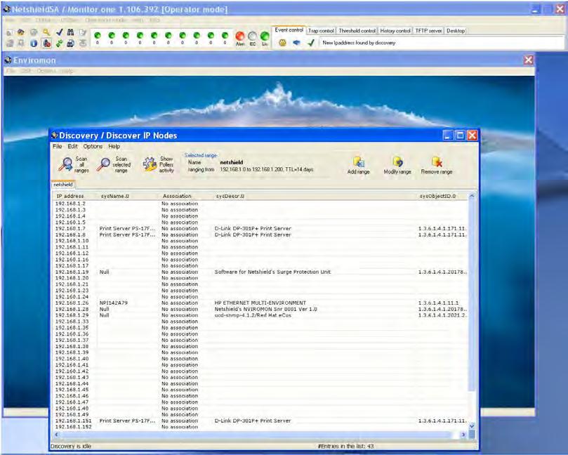
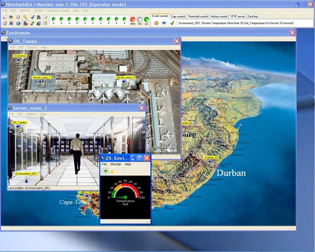
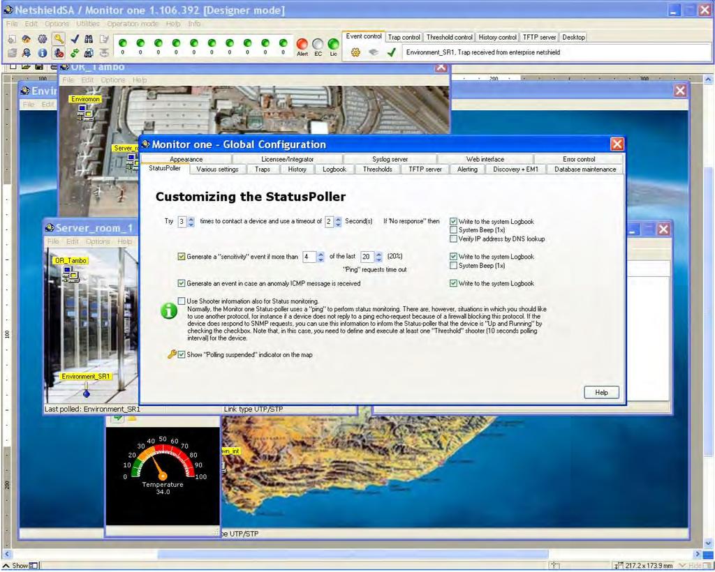
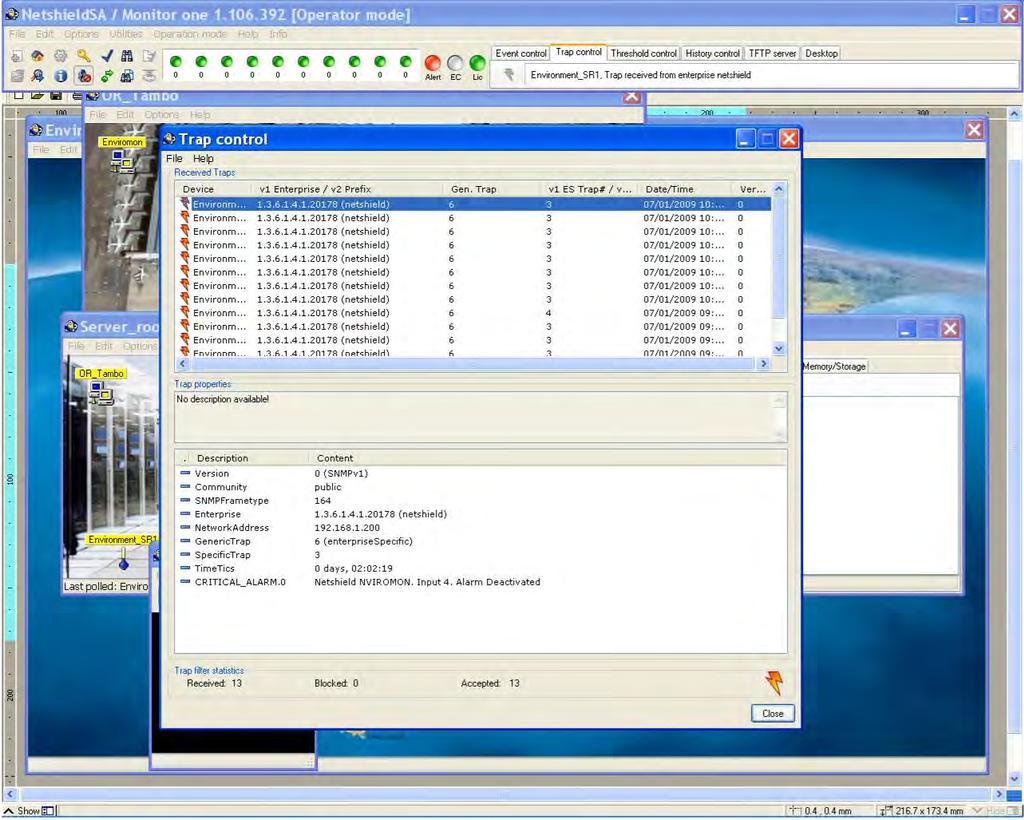
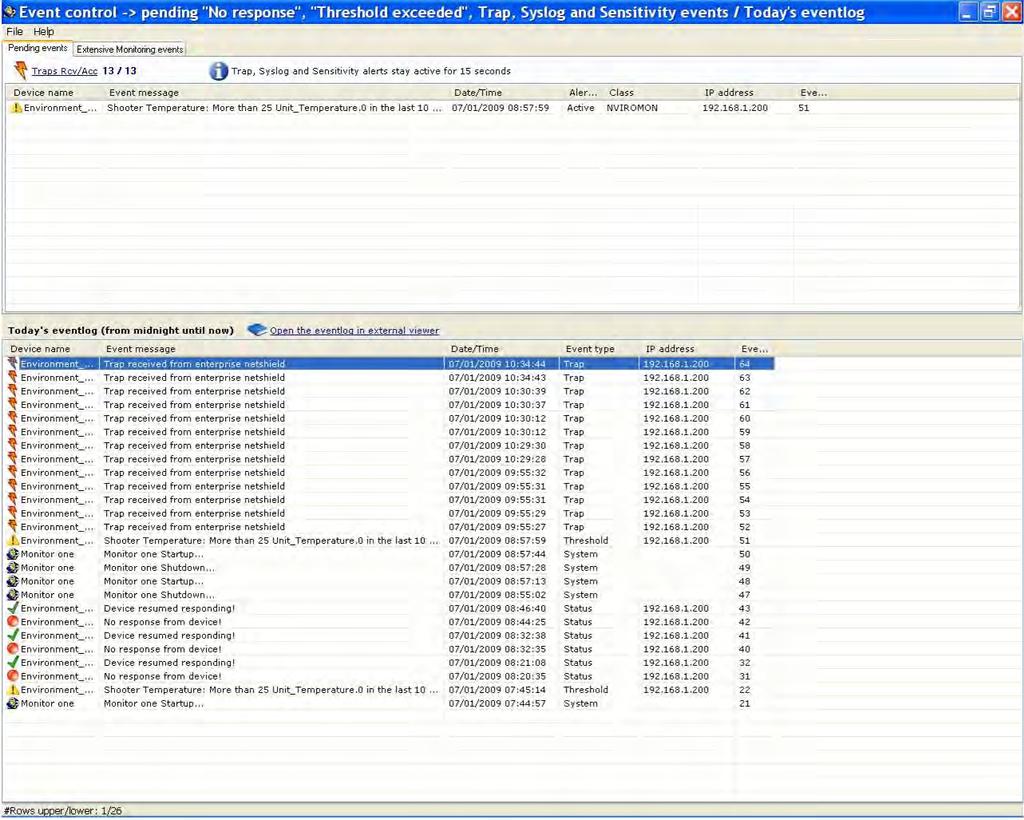
14 9 Netshield SNMP Management software Monitor One The NLMAINUNIT-2U-E is remotely configured, controlled and monitored by the Netshield SNMP based management information system (Monitor One). This software uses the SNMP protocol over a LAN connection to communicate with all the NLMAINUNIT-2U-E units connected to the network. There are over 800 configurable settings to control the NLMAINUNIT-2U-E unit. These settings range from Site name through to environmental limit settings. Other management control software should also be able to interface with the NLMAINUNIT-2U-E unit with the SNMP protocol. 9.1 Installation and setup of Netshield SNMP Management Software (Monitor One) Install the software on any personal computer that has access to the local network or the internet. The software is available for download on the netshieldsa.com website A complete manual of the management software (Monitor One) is available for download on the netshieldsa.com website The following is an overview of the management software (Monitor One) 12

15 13
16 14

17 15

18 16
19 9.2 SNMP objects The descriptions of all the object identifiers are included in the program and have a database for logging of the system statuses and traps. The SNMP objects looks like the following, where the Netshield enterprise number is SPS-MIB.iso.org..dod.internet.private.enterprises.netshield.products.SPS READINGS Surge Protection System SPSVoltageReading Integer V SPSCurrentReading Integer ma SPSPowerReading Integer W SPSAccPowerReading String kwh SPSTemperatureReading Integer Degrees Celsius SPSMainsTripIndicator Boolean 0 / 1 0 = No Trip & 1 = Trip occured SPSMainsProtectorIndicator Boolean 0 / 1 0 = Protection OK &1 = Protection Fault SPSMainsSurgeProtectionIndicator Boolean 0 / 1 0 = Protection OK & 1 = Protection Fault HighPowerProbe HPwrProbe1VoltageReading Integer V HPwrProbe1Currentreading Integer ma HPwrProbe1PowerReading Integer W HPwrProbe1AccPowerReading String kwh HPwrProbe1TemperatureReading Integer Degrees Celsius HPwrProbe1MainsTripIndicator Boolean 0 / 1 0 = No Trip & 1 = Trip occured HPwrProbe1MainsProtectorIndicator Boolean 0 / 1 0 = Protection OK & 1 = Protection Fault HPwrProbe1PresenceIndicator Boolean 0 / 1 0 = Probe unavailable & 1 = Probe available HighPowerProbe HPwrProbe2VoltageReading Integer V HPwrProbe2Currentreading Integer ma HPwrProbe2PowerReading Integer W HPwrProbe2AccPowerReading String kwh HPwrProbe2TemperatureReading Integer Degrees Celsius HPwrProbe2MainsTripIndicator Boolean 0 / 1 0 = No Trip & 1 = Trip occured HPwrProbe2MainsProtectorIndicator Boolean 0 / 1 0 = Protection OK & 1 = Protection Fault HPwrProbe2 PresenceIndicator Boolean 0 / 1 0 = Probe unavailable & 1 = Probe available DataProtectionModules Slot Slot1PresentReading Boolean 0 / 1 0 = Module Not Present & 1 = Module Present Slot1ControlReading Boolean 0 / 1 0 = Ctrl Unavailable & 1 = Ctrl Available Slot1IndicateReading Boolean 0 / 1 0 = Ind Unavailable & 1 = Ind Available Slot Slot2PresentReading Boolean 0 / 1 0 = Module Not Present & 1 = Module Present Slot2ControlReading Boolean 0 / 1 0 = Ctrl Unavailable & 1 = Ctrl Available Slot2IndicateReading Boolean 0 / 1 0 = Ind Unavailable & 1 = Ind Available Slot Slot3PresentReading Boolean 0 / 1 0 = Module Not Present & 1 = Module Present Slot3ControlReading Boolean 0 / 1 0 = Ctrl Unavailable & 1 = Ctrl Available Slot3IndicateReading Boolean 0 / 1 0 = Ind Unavailable & 1 = Ind Available SETTINGS SurgeProtectionSystem VoltageSettings SPSVoltageUpperLimit Integer V Get Voltage limit or set new limit for trap SPSVoltageLowerLimit Integer V Get Voltage limit or set new limit for trap CurrentSettings SPSCurrentUpperLimit Integer 0 16 A Get Current limit or set new limit for trap SPSCurrentLowerLimit Integer 0 16 A Get Current limit or set new limit for trap SPSCurrentTripLimit Integer 0 16 A Get Current limit or set new limit for trap PowerSettings SPSPowerUpperLimit Integer W Get Power limit or set new limit for trap SPSPowerLowerLimit Integer W Get Power limit or set new limit for trap TemperatureSettings SPSTempUpperLimit Integer C Get Temperature limit or set new limit for trap SPSTempLowerLimit Integer C Get Temperature limit or set new limit for trap SPSSettings SPSSiteName String Size(22) Get or Set the site name of the unit SPSMainsON/OFF Boolean 0 / 1 0 = Switch Mains off & 1 = Switch Mains on SPSTime String Size(6) Get / Set Time eg. 12: SPSDate String Size(9) Get / Set Date eg. 28/02/ SPSSerialNumber String Size(31) Get the serial number, and version of unit SPSRestoreDefaults String Integer Set with 123 to restore to defaults HighPowerProbe VoltageSettings HPwrProbe1VoltageUpperLimit Integer V Get Voltage limit or set new limit for trap HPwrProbe1VoltageLowerLimit Integer V Get Voltage limit or set new limit for trap CurrentSettings HPwrProbe1CurrentUpperLimit Integer 0 32 A Get Current limit or set new limit for trap HPwrProbe1CurrentLowerLimit Integer 0 32 A Get Current limit or set new limit for trap
20 HPwrProbe1CurrentTripLimit Integer 0 32 A Get Current limit or set new limit for trap PowerSettings HPwrProbe1PowerUpperLimit Integer W Get Power limit or set new limit for trap HPwrProbe1PowerLowerLimit Integer W Get Power limit or set new limit for trap TemperatureSettings HPwrProbe1TempUpperLimit Integer C Get Temperature limit or set new limit for trap HPwrProbe1TempLowerLimit Integer C Get Temperature limit or set new limit for trap ProbeSettings HPwrProbe1SiteName String Size(22) Get or Set the site name of the unit HPwrProbe1MainsON/OFF Boolean 0 / 1 0 = Switch Mains off & 1 = Switch Mains on HPwrProbe1SerialNumber String Size(31) Get the serial number, and version of unit HPwrProbe1Presence Integer 0-1 Force whether Probe1 is present on system HighPowerProbe VoltageSettings HPwrProbe2VoltageUpperLimit Integer V Get Voltage limit or set new limit for trap HPwrProbe2VoltageLowerLimit Integer V Get Voltage limit or set new limit for trap CurrentSettings HPwrProbe2CurrentUpperLimit Integer 0 32 A Get Current limit or set new limit for trap HPwrProbe2CurrentLowerLimit Integer 0 32 A Get Current limit or set new limit for trap HPwrProbe2CurrentTripLimit Integer 0 32 A Get Current limit or set new limit for trap PowerSettings HPwrProbe2PowerUpperLimit Integer W Get Power limit or set new limit for trap HPwrProbe2PowerLowerLimit Integer W Get Power limit or set new limit for trap TemperatureSettings HPwrProbe2TempUpperLimit Integer C Get Temperature limit or set new limit for trap HPwrProbe2TempLowerLimit Integer C Get Temperature limit or set new limit for trap ProbeSettings HPwrProbe2SiteName Integer W Get Power limit or set new limit for trap HPwrProbe2MainsON/OFF Integer W Get Power limit or set new limit for trap HPwrProbe2SerialNumber String Size(31) Get the serial number, and version of unit HPwrProbe2Presence Integer 0-1 Force whether Probe1 is present on system Traps TrapString SPSMessageString String Size(100) Last sent trap message Reading Subtree Under the Readings subtree are four other subtrees. All the reading object identifiers (Voltage, Current, Power, ACC Power, Temperature, Strip status and Mains protection status) of the NLMAINUNIT and the two PROBES inside the NLPDU unit can be found under their corresponding subtree. At the bottom of the two HighPowerProbe subtrees are the probe presence indicators. A 1 will indicate that the unit is up and running and a 0 indicates that the probe is not connected. The three available data protection modules statuses are under the DataProtectionModules subtree. Indicating the presence, control and the indicate statuses. 9.4 Settings Subtree Under the settings subtree are the three surge protection unit setting (NLMAIN, PROBE1 and PROBE2). In these subtrees are the Out of Limits settings. These are the values where the system will send out SNMP traps to indicate critical conditions. The current trip setting, 1-16A for the MAINUNIT or 1-32A for the PROBES, is settable under the CurrentSettings subtree of each unit respectively. The mains can be switched on or off and the sitename can be changed under the Probe- / SPSsettings. The time and date of the system are also settable / readable in the SPSsettings subtree. Please take note: When 123 is set on the SPSRestoreDefaults, under the SPSsettings subtree, the NLMAINUNIT will discard the available probes allocated to the MAINUNIT. Use this setting only when new Probes replace old Probes. 18
21 The user can force if a probe should be enabled or disabled at the HPwrProbe1/2Presence by setting the integer number 1 for enable or 0 for disable via the SNMP interface. 9.5 Traps Subtree Under the Traps subtree the Object identifier SPSMessageString contains the message of the last trap that was sent to the manager system. If there is a communications error between the SNMP engine and the embedded system inside the MAINUNIT the trap SPSAlarmSerialCom will indicate it with a 1 otherwise the object identifier will indicate a Specifications 10.1 NLMAINUNIT-2U-E specifications Mains: Unit Input / Output Specifications: Category Minimum Nominal Maximum Units Input / Output Voltage: V(ac) Input Current: A(ac) Power Usage: W Output Current (load): A The unit has high surge handling capability with over current fusing and a visual fault indication on the unit s display. A resettable current trip, up to 16 Amp, can be configured through the SNMP interface. Surge Specifications: Category Minimum Nominal Maximum Units Max Continuous Operating Voltage: V(ac) Max Continuous Operating Current: A Maximum Surge Current: ka Clamping Voltage at 100A: V Clamping Voltage at 5000A: - - <900 V Response Time: - - <25 ns External Data Protection Modules (WAN): The Surge Protection System has three slots available for external data protection modules. These modules can be x.21, Ethernet, ADSL or E1. X.21 (V.11 / RS422) Module Specifications (1 channel per module): Category Specification Units Line Specification: 120 Ω Bandwidth: Mbps Optical Isolation: 15 kv Connectors: DB15 Male & DB15 Female - 19
22 Ethernet Module Specifications (1 channel per module): Category Specification Units Line Specification: IEEE 802.3af Interface (PoE) - Bandwidth: 10, 100, 1000 Mbps Clamping Voltage (Ethernet Lines): 10 V Clamping Voltage (PoE Lines): 50 V Connectors: RJ45 - ADSL Module Specifications (1 channel per module): Category Specification Units Line Specification: POTS - Bandwidth: Mbps Clamping Voltage: 140 V Connectors: RJ-11 - E1 Module Specifications (2 channel per module): Category Specification Units Line Specification: ITU-T G Bandwidth: Mbps Clamping Voltage: 140 V Connectors: RJ External Interface Port: With SNMPV1 the user is able to manage the Surge Protection System. Limits like voltage upper and lower limits can be set up where the internal management server will transmit SNMP traps to indicate alarm conditions. The user can switch the mains on or off, setup the current trip limit etc. Management Port (Ethernet): Category Specification Units Line Specification: IEEE Protocol: SNMP V1, TELNET Bandwidth: 10, 100 Adaptive Mbps Connectors: RJ-45 - Probe / Sensor Port (RS485): Category Specification Units Line Specification: RS485 - Bandwidth: 9600 bps Connectors: RJ-45 - General Purpose I/O Port: Category Specification Units Number of Inputs Channels: 1 Optically Isolated - Number of Outputs Channels: 1 Normally Open / Closed Contact - Input Voltage on Input Channel: V(dc) Maximum Voltage on Output Channel: 24 V(dc) Maximum Current on Output Channel: 1 A 20
23 General Specifications: Environment: Category Specification Units Operating Temperature: 0-50 ºC Storage Temperature: ºC Humidity: 5 85 (Non condensing) % Dimensions (l x b x h): 480 x 80 x 88 mm Weight: 2.5 kg 10.2 NLPDU specifications Mains: Unit Mains Input / Output Specifications: Category Minimum Nominal Maximum Units Input / Output Voltage: V(ac) Input Current: A(ac) Power Usage: W Output Current: A(ac) The unit has high surge handling capability with over current fusing and a resetable current trip setting. Surge Specifications: Category Minimum Nominal Maximum Units Max Continuous Operating Voltage: V(ac) Max Continuous Operating Current: A Maximum Surge Current: 8 ka Clamping Voltage at 100A: 700 V Clamping Voltage at 5000A: <900 V Response Time: <25 ns External Interface Ports: The High Power Probe can work as a stand alone unit or it can work in conjunction with the Netshield NLMAINUNIT-2U-E or the Netshield NVIROMON unit. Via the Netshield Sensor Protocol the probe can be configured and managed from a remote unit or site. These settings are typically to switch the mains on or off, setup the current trip limit etc. Interface Port (RS485): Category Specification Units Line Specification: RS485 - Bandwidth: 9600 bps Connectors: RJ General Specifications: Environment: Category Specification Units Operating Temperature: 0-50 ºC Storage Temperature: ºC Humidity: 5 85 (Non condensing) % Dimensions (l x b x h): 482 x 285 x 88 Mm Weight: 6 Kg 21
24 10.3 NLMAINUNIT-2U-E & NLPDU Measurements The system measures the following and are displayed on the LCD: Category NLMAINUNIT NLPDU Units Voltage: V Current: A Apparent Energy: VA Accumulated Energy: kwh Temperature: ºC 11. Packaging list NLMAINUNIT-2U-E NLDPU Male to female power cord 12. Trouble Shooting Fault: The NLMAINUNIT can not be found on the IP network. Solution: Make sure the IP address is set to be static and in the same IP range. Connect to the NLMAINUNIT via TELNET with the default IP address: and change the IP address with menu option 0. Fault: The manager software can not detect the unit but a ping to the unit works. Solution: Make sure that the manager computer has a static IP address and that the manager IP address is set in the NLMAINUNIT SNMP settings via TELNET, menu option 1. Check the read and write community strings of the manager and the NLMAINUNIT. Default is public for the read community and private for the write community. Fault: The NLMAINUNIT does not detect the PROBES inside the NLDPU unit via the display or via the manager software. Solution: Do an address reallocation. Disconnect the RS485 cable between Probe1and Probe2 but make sure that the RS485 cable from the NLMAINUNIT and PROBE1 is still connected. Press and hold the TRIP button on both PROBES of the NLPDU for more than 16 seconds. 22
25 With the SNMP interface, expand the Setting subtree, the SurgeProtectionSettings subtree, the SPSSettings subtree and set 123 in the SPSRestoreDefaults object indentifier to release all the allocated Probe addresses. Switch off the mains power feed of both Probes inside the NLPDU. After 3 5 seconds switch on the power feeds again. The PROBE1 NOT AVAILABLE indication on the display should change and the energy information should be visible on the display. Connect the cable between the two Probes again and Probe2 should be registered on the NLMAINUNIT. Fault: The NTU does not pick up the data / clocks from the router or visa versa. Solution: Check the cable connections to the Data Protection Module. Make sure the Module is properly mated with the NLMAINUNIT. Check if the NTU / Router work when the input cable to the x.21 Data Protection Module is directly connected to the output cable. If it starts to work, the module is faulty. Not, one of the cables is faulty. Problem Probable cause Remedy 23
Cisco CRS 16-Slot Chassis Power Systems
 This chapter includes the following sections: Power specifications are provided in Technical Specifications Power Systems Overview, on page 1 Power Component Information Common to the Two Types of Power
The power behind competitiveness. Delta Infrasuite Power Management. Power Distribution Unit. User Manual.
 The power behind competitiveness Delta Infrasuite Power Management Power Distribution Unit User Manual www.deltapowersolutions.com Save This Manual This manual contains important instructions and warnings
UPS Series. features: uninterruptible power supply. what great systems are built on.
 uninterruptible power supply uninterruptible power supply with energy saver design that is optimized to address the needs of A/V systems features: Pure Sine Wave technology with Automatic Voltage Regulation
the data line series
 the data line series 12-00131 OUTDOOR SINGLE PORT POE RJ45 SURGE ARRESTOR rev0-10/100/1000 Base-T CAT5e Protection - IEEE 802.3 A/F Power Mode B - Solid-state silicon-avalanche diodes with internal TVS
ATS-16 HV USER MANUAL. Automatic Transfer Switch 16A / 230Vac V090318
 ATS-16 HV Automatic Transfer Switch 16A / 230Vac USER MANUAL V090318 SAFETY Intended use The ATS-16 HV device serves as a power source selector to provide improved power supply for connected loads. ATS-16
MAINTENANCE MANUAL. EDACS REDUNDANT POWER SUPPLY SYSTEM 350A1441P1 and P2 POWER MODULE CHASSIS 350A1441P3, P4, AND P5 POWER MODULES TABLE OF CONTENTS
 MAINTENANCE MANUAL EDACS REDUNDANT POWER SUPPLY SYSTEM 350A1441P1 and P2 POWER MODULE CHASSIS 350A1441P3, P4, AND P5 POWER MODULES TABLE OF CONTENTS SPECIFICATIONS*... 2 INTRODUCTION... 3 DESCRIPTION...
Overview. Features CHAPTER
 CHAPTER 2 This chapter provides these topics that describe the Catalyst 2955 switch, hereafter referred to as the switch. Features, page 2-1 Front-Panel Description, page 2-3 Rear-Panel Description, page
Model 160. Model 186. Model 247. Surge Protective Devices. Installation & Operation Manual. Model 160. Model 186. Model 247 (EDCO RM-CX06-16R)
") Surge Protective Devices Installation & Operation Manual Model 160 (16-Channel Coaxial) Model 186 (16 or 48 Channel Hi Speed Data Line Protector) Model 247 (120VAC Active Tracking Filter) Model 160 (EDCO
Surge Protective Devices Installation & Operation Manual Model 160 (16-Channel Coaxial) Model 186 (16 or 48 Channel Hi Speed Data Line Protector) Model 247 (120VAC Active Tracking Filter) Model 160 (EDCO
Installing the Cisco AS5400XM Universal Gateway
 CHAPTER 3 Installing the Cisco AS5400XM Universal Gateway This chapter guides you through the installation of the Cisco AS5400XM universal gateway and includes the following sections: Setting Up the Chassis,
Delivered the Way Yo u Want
 SENSAPHONE IMS-4000 Infrastructure Monitoring System Mo nito r What Yo u Want Delivered the Way Yo u Want THE SENSAPHONE IMS-4000 MONITORS AND REPORTS THE INFORMATION THAT YOU NEED TO KNOW: Get critical
Power Distribution. For technical support call Online catalog available at leviton.com 461
 INDEX FLX Series... 463 Switched Series... 464 Metered Series... 465 P1000 Series... 466 5500 & 5505 Series... 467 4500 Series... 468 For technical support call 800-824-3005 Online catalog available at
Metered Rack PDU Rack PDU, Metered, Zero U,12.5kW,208V,(30)C13, (6)C19; 10' Cord
C13, (6)C19; 10' Cord") Metered Rack PDU Rack PDU, Metered, Zero U,12.5kW,208V,(30)C13, (6)C19; 10' Cord APC Metered Rack PDU, Input: 208V 3PH, Input Connections: Hubbell CS8365C, Cord Length: 10 feet ( 3.05 meters ), Output:
Metered Rack PDU Rack PDU, Metered, Zero U,12.5kW,208V,(30)C13, (6)C19; 10' Cord APC Metered Rack PDU, Input: 208V 3PH, Input Connections: Hubbell CS8365C, Cord Length: 10 feet ( 3.05 meters ), Output:
Metered Rack PDU Rack PDU, Metered, Zero U, 10A, 230V, (16) C13
 C13") Metered Rack PDU Rack PDU, Metered, Zero U, 10A, 230V, (16) C13 APC Metered Rack PDU, Input: 230V, Input Connections: IEC-320 C14, Cord Length: 10 feet ( 3.05 meters ), Output: 230V, Output Connections:
Metered Rack PDU Rack PDU, Metered, Zero U, 10A, 230V, (16) C13 APC Metered Rack PDU, Input: 230V, Input Connections: IEC-320 C14, Cord Length: 10 feet ( 3.05 meters ), Output: 230V, Output Connections:
5.8kW Single-Phase Switched PDU, 208/240V Outlets (8 C13 & 6 C19), L6-30P, 15ft Cord, 2U Rack-Mount, TAA
, L6-30P, 15ft Cord, 2U Rack-Mount, TAA") Management Interface The management interface for this PDU model is transitioning to a new technology platform. The new interface can be distinguished by a USB-A port (for EnviroSense2 modules) in place
Management Interface The management interface for this PDU model is transitioning to a new technology platform. The new interface can be distinguished by a USB-A port (for EnviroSense2 modules) in place
Prisma II Platform. Optoelectronics
 Optoelectronics Prisma II Platform Description In optical transmission systems, the network platform forms the foundation of the product family. The Prisma II platform provides network operators with the
Innovative. Engineering. Power. structure source. Making the complex, simple. Structure Source PDU s
 Structure Source PDU s Innovative Power Engineering High Quality Power Distribution for the Data Centre structure source Making the complex, simple structure source product range Rack and Server Power
APC Next Generation Rack ATS
 APC Next Generation Rack ATS Automatic switching power redundancy for single corded equipment. Next Generation Rack ATS with multiple outlets eliminate the need for a secondary Rack PDU downstream of Rack
User Manual. Per Port Monitoring Models
 User Manual Per Port Monitoring Models Table of Contents 1. Introduction... 1 2. Package Contents... 2 3. Function... 3 4. Installation... 5 5. Web Interface... 6 1. Introduction The ServerLink Per Port
iconverter 2-Module Power Chassis
 iconverter 2-Module Power Chassis User Manual 38 Tesla, Irvine, CA 92618 USA Phone: (949) 250-6510; Fax: (949) 250-6514 Page 1 Warning The operating description in this Instruction Manual is for use by
Switched XPDU. 15A Model. User & Installation Manual Xtreme Power Conversion Corporation. All rights reserved.
 Switched XPDU 15A Model User & Installation Manual www.xpcc.com 2014. All rights reserved. (Rev 10/02/14) Table of Contents Introduction...4 PDU Package...4 Function...4 Interface...4 Installation...5
SmartPro 120V 750VA 600W Line-Interactive Sine Wave UPS, 1U Rackmount, Pre-installed WEBCARDLX Network Interface, USB, DB9 Serial
 SmartPro 120V 750VA 600W Line-Interactive Sine Wave UPS, 1U Rackmount, Pre-installed WEBCARDLX Network Interface, USB, DB9 Serial MODEL NUMBER: SMART750RM1UN Highlights.75kVA / 750VA / 600W line interactive
Single Phase Systems-North American PC125/PC420 Series
 Single Phase Systems-North American PC125/PC420 Series Enclosure Power Distribution Units (epdu ) PC125-C Front RACK MOUNTED 19 x 3.4 (2U) x 8.5. Approximate shipping weight: 19 lbs. (12) NEMA OUTLETS
PDU - Overview / Non-Intelligent PDU s
 PDU - Overview / Non-Intelligent PDU s InfraPower Rack Power Distribution Units InfraPower Rack PDU Range Switched (Outlet kwh PDU) Monitored (kwh PDU) Metered Basic WSi WS W MD Basic Outlet Measurement
SmartOnline Expandable Rack / Tower UPS System Online, double-conversion protection for mission critical applications
 SmartOnline Expandable Rack / Tower UPS System Online, double-conversion protection for mission critical applications Model #: SU6000RT3UHV 6000VA online 6U rack / tower UPS (3U Power Module + 3U Battery
CS-12HDE444C8 (Master) Key Features. CL-12HDE444C8 (Link)
 Key Features. CL-12HDE444C8 (Link)") CS-12HDE444C8 (Master) CL-12HDE444C8 (Link) The Server Technology Smart PDU provides local LED input current monitoring, allowing IT personnel to determine safe levels of loading on a per-phase basis while
CS-12HDE444C8 (Master) CL-12HDE444C8 (Link) The Server Technology Smart PDU provides local LED input current monitoring, allowing IT personnel to determine safe levels of loading on a per-phase basis while
IBM eserver System x and BladeCenter IBM DPI PDU+ Power Distribution Units. 10/9/ IBM Corporation
 IBM eserver System x and BladeCenter IBM DPI PDU+ Power Distribution Units 10/9/2007 Agenda System x Options Program and PDU market overview What is a PDU? Why do you need an IBM DPI PDU? IBM DPI PDU offering
4 Port Industrial RS-232 / 422 / 485 Serial to IP Ethernet Device Server - PoE-Powered - 2x 10/100Mbps Ports
 4 Port Industrial RS-232 / 422 / 485 Serial to IP Ethernet Device Server - PoE-Powered - 2x 10/100Mbps Ports Product ID: NETRS42348PD The PoE-powered NETRS42348PD 4-Port Industrial Serial Device Server
High Power over Ethernet Midspans PD Port Model PD Port Model
 Data and Power on a Single Line High Power over Ethernet Midspans PD-8006-6 Port Model PD-8012-12 Port Model User Guide Notice The information contained herein is believed to be accurate and reliable at
Industrial PoE Media Converter
 Quick Start Guide This quick start guide describes how to install and use the Industrial PoE Media Converter. This is the Media Converter of choice for harsh environments constrained by space. Physical
Table of Contents. 1. Introduction Package Contents Function Installation Web Interface... 5
 User Manual Table of Contents 1. Introduction... 1 2. Package Contents... 2 3. Function... 3 4. Installation... 4 5. Web Interface... 5 6. Specifications... 8 1. Introduction The ServerLink PDU is a network
Self-Contained Equipment Cabinets
 Self-Contained Equipment Cabinets The water and dust proof self-contained cabinets houses all the services required to service, power backup and protect your network core or distribution equipment required
25.2kW 3-Phase Switched PDU, LX Platform Interface, 240V Outlets (24 C13/6 C19), Touchscreen LCD, IEC A Red 415V, 0U, TAA
, Touchscreen LCD, IEC A Red 415V, 0U, TAA") 25.2kW 3-Phase Switched PDU, LX Platform Interface, 240V Outlets (24 C13/6 C19), Touchscreen LCD, IEC 309 60A Red 415V, 0U, TAA MODEL NUMBER: PDU3XEVSR6G60B Highlights 25.2kW 240V 3-phase switched 1.8m
25.2kW 3-Phase Switched PDU, LX Platform Interface, 240V Outlets (24 C13/6 C19), Touchscreen LCD, IEC 309 60A Red 415V, 0U, TAA MODEL NUMBER: PDU3XEVSR6G60B Highlights 25.2kW 240V 3-phase switched 1.8m
OPERATING MANUAL AC POWER DISTRIBUTION UNITS VIGILANT SERIES
 OPERATING MANUAL AC POWER DISTRIBUTION UNITS VIGILANT SERIES www.unipowerco.com Manual No. PDUAC1USM-2 pduac1us-man-rev2-0115.indd 2015 UNIPOWER LLC All Rights Reserved NORTH AMERICA 3900 Coral Ridge Drive,
Basic PDU Modules SW Meter PDU SW Meter Switch PDU SW Three Phase PDU. How to install 11-12
 01-02 Basic PDU 03-04 Modules 05-06 SW Meter PDU 07-08 SW Meter Switch PDU 09-10 SW Three Phase PDU 11-12 How to install Safewell Basic PDU Series Model:SW-1U-8IEC13-K Product Description Size 19 * 1U
F8008. Fiber Modem for up to 4E1 /8E1 +RS232+Ethernet. + optional V.35/QFXS/QFXO
 F8008 Fiber Modem for up to 4E1 /8E1 +RS232+Ethernet + optional V.35/QFXS/QFXO Description F8008 is a fiber optical multiplexer of new generation different from the traditional PDH, multiplexing 1 full
MAJOR VA Power Inverter
 MAJOR500-500 VA Power Inverter The Major500 is a highly reliable, telecom quality, DC to AC power inverter. The Major500 features full electronic protection, high efficiency and low output noise. The built-in
ECO Series 120V 850VA 425W Energy-Saving Standby UPS with USB port, LCD Display and 12 Outlets
 ECO Series 120V 850VA 425W Energy-Saving Standby UPS with USB port, LCD Display and 12 Outlets MODEL NUMBER: ECO850LCD Description The ECO850LCD ultra-compact green UPS offers complete protection from
Installing the IPS 4345 and IPS 4360
 CHAPTER 4 Installing the IPS 4345 and IPS 4360 Contents This chapter describes the Cisco IPS 4345 and the IPS 4360, and includes the following sections: Installation Notes and Caveats, page 4-1 Product
SmartPro 230V 3kVA 2.25kW Line-Interactive UPS, Tower, Extended Run, SNMPWEBCARD Option, USB, DB9 Serial
 SmartPro 230V 3kVA 2.25kW Line-Interactive UPS, Tower, Extended Run, SNMPWEBCARD Option, USB, DB9 Serial MODEL NUMBER: SMARTINT3000VS Highlights 3kVA / 3000VA / 2250W line interactive tower UPS system
SmartOnline 120V 3kVA 2.7kW Double- Conversion UPS, 3U Rack/Tower, Extended Run, WEBCARDLX Network Interface, LCD, USB, DB9
 SmartOnline 120V 3kVA 2.7kW Double- Conversion UPS, 3U Rack/Tower, Extended Run, WEBCARDLX Network Interface, LCD, USB, DB9 MODEL NUMBER: SU3000RTXLCD3N Highlights Zero transfer time suitable for advanced
Model: POE-SW1602E. Features
 Model: POE-SW1602E Features 16-Port 10/100Mbps IEEE 802.3af/at PoE Switch (End-Span PSE) Comply with IEEE802.3, IEEE802.3u, IEEE802.3af/at standards Support IEEE802.3x full-duplex flow control; support
Smart Pro Rack/Tower UPS Intelligent, line-interactive network power management system
 Smart Pro Rack/Tower UPS Intelligent, line-interactive network power management system Model #: SMART1000RM2U 1000VA line interactive 2U rack/tower UPS system with sine wave output in AC and battery mode
Surge Protection for Surveillance Systems
 Surge Protection for Surveillance Systems 1-in-1 Protection for Network Cameras 2-in-1 Protection for Power and Audio/Video Signals 3-in-1 Protection for Power, Audio/Video and PTZ Control Signals Application:
Technical documentation NLS-3000 NAVIGATION LIGHT CONTROL PANEL
 Technical documentation LIGHT CONTROL PANEL For use on seagoing vessels Change status Version Date Author Checked Remark 0.1 07.08.2008 STO HN 1. Edition Page 1 of 26 Table of contents 1. Application and
RT12-240V/2.4kW Rectifier Specification
 The RT12-240V/2.4kW is a switched mode rectifier (SMR) module that delivers up to 2.4kW of output power (and up to 11A output current) into a 240V nominal DC system. The RT12 suits AC supply voltages between
Click Desktop Kit. Click Desktop Kit
 Click Desktop Kit Click Desktop Kit The Click Desktop Kit is a desktop-mounted set that gives you the building blocks necessary to work with your Click modules at your computer, whether you re testing
INSTALLATION INSTRUCTIONS FOR THE BV10-100/1000
 INSTALLATION INSTRUCTIONS FOR THE BV10-100/1000 This document describes the basic steps for installing your BV10-100 or BV10-1000. For detailed information about the BV10-100/1000, see the Ethernet Performance
Metered Rack PDU Rack PDU, Metered, Zero U, 20A, 120V, (24) NEMA 5-20R
 NEMA 5-20R") Metered Rack PDU Rack PDU, Metered, Zero U, 20A, 120V, (24) NEMA 5-20R APC Metered Rack PDU, Input: 120V, Input Connections: NEMA L5-20P, Cord Length: 10 feet ( 3.05 meters ), Output: 120V, Output Connections:
Metered Rack PDU Rack PDU, Metered, Zero U, 20A, 120V, (24) NEMA 5-20R APC Metered Rack PDU, Input: 120V, Input Connections: NEMA L5-20P, Cord Length: 10 feet ( 3.05 meters ), Output: 120V, Output Connections:
2U Congestion Alert Rack Insert for UK
 2U Congestion Alert Rack Insert for UK 2U Congestion Alert Rack Insert for UK The 2U congestion alert rack insert comes fully assembled, wired and ready to be installed in a rack. The rack provides communications,
SmartPro UPS System Intelligent, line-interactive battery backup and network power management
 SmartPro UPS System Intelligent, line-interactive battery backup and network power management Model #: SMART2200VS 2200VA line interactive tower UPS system Enhanced communication ports (2 USB / 2 DB9),
1PH RACK 19 SINGLE PHASE UPS Rev. 11 SR 6kVA 10kVA
 The SR series on line double conversion UPS with full time Digital Signal Processor control technology is the perfect solution for mission critical users who demand high reliability, availability and performance
Metered Rack PDU Rack PDU, Metered, Zero U, 5.7kW,208V,(36)C13& (6)C19; 10' Cord
C13& (6)C19; 10' Cord") Metered Rack PDU Rack PDU, Metered, Zero U, 5.7kW,208V,(36)C13& (6)C19; 10' Cord APC Metered Rack PDU, Input: 208V 3PH, Input Connections: NEMA L21-20P, Cord Length: 10 feet ( 3.05 meters ), Output: 208V,
Metered Rack PDU Rack PDU, Metered, Zero U, 5.7kW,208V,(36)C13& (6)C19; 10' Cord APC Metered Rack PDU, Input: 208V 3PH, Input Connections: NEMA L21-20P, Cord Length: 10 feet ( 3.05 meters ), Output: 208V,
SmartOnline 208/240V 3kVA 2.4kW Double-Conversion UPS, 3U Rack/Tower, Extended Run, SNMPWEBCARD Option, DB9 Serial
 SmartOnline 208/240V 3kVA 2.4kW Double-Conversion UPS, 3U Rack/Tower, Extended Run, SNMPWEBCARD Option, DB9 Serial MODEL NUMBER: SU3000RTXL3UHV Highlights 3000VA / 3kVA / 2400 watt on-line double-conversion
BACnet. b3810 Series Local Controllers
 BACnet b380 Series Local Controllers The Andover Continuum TM b380 series controllers are designed for control of Air Handling Units, Roof Top Units, and other mechanical plant equipment. 0 Features Choose
NMEA Expander. Operation And. Installation Manual
 NMEA Expander Operation And Installation Manual XXXXXX_20130331 Revision B0 Syberg Maritim 1. OPERATION AND CONFIGURATION... 3 SYSTEM SUMMARY... 3 INPUT POWER SUPPLY, D CONFIGURATION... 4 INPUT POWER SUPPLY,
ECO Series 120V 850VA 425W Energy-Saving Standby UPS with USB, LCD Display and 12 Outlets
 ECO Series 120V 850VA 425W Energy-Saving Standby UPS with USB, LCD Display and 12 Outlets MODEL NUMBER: ECO850LCD Highlights 850VA ultra-compact 120V standby UPS, LCD status and control display Maintains
EnerSure Installation Guide
 EnerSure Installation Guide Danger!!! The electrical components of this system may contain voltage and /or amperage sufficient to injure or kill. Installation is only to be performed by a licensed, bonded
DATA SHEET. Advanced Power Meter, APM 380 & APM 305
 DATA SHEET Advanced Power Meter, APM 380 & APM 305 Easy installation Monitors all 3 phases 5 optional communication interfaces Phase error detection Low power consumption Two-pulse output DEIF A/S Frisenborgvej
CS-10H0A413H3 (Master) Key Features. CL-10H0A413H3 (Link)
 Key Features. CL-10H0A413H3 (Link)") CS-10H0A413H3 (Master) CL-10H0A413H3 (Link) The Server Technology Smart PDU provides local LED input current monitoring, allowing IT personnel to determine safe levels of loading on a per-phase basis while
CS-10H0A413H3 (Master) CL-10H0A413H3 (Link) The Server Technology Smart PDU provides local LED input current monitoring, allowing IT personnel to determine safe levels of loading on a per-phase basis while
CRAGG RAILCHARGER Instruction Manual for 10DTC-12V 20DTC-12V 30DTC-24V 40DTC-12V 60DTC-12V
 CRAGG RAILCHARGER for 10DTC-12V 20DTC-12V 30DTC-24V 40DTC-12V 60DTC-12V Contents 1 Warnings, Cautions, and Notes... 1 2 Description... 2 3 Features... 2 3.1 STANDARD FEATURES... 2 3.2 CHARGER REGULATION...
Switched Rack Power Distribution Unit
 Switched Rack Power Distribution Unit AS-216-520-30A-L530 Installation and Quick Start Contents Product Description and Inventory...................... 1 AS-216-520-30A-L530....................... 1 Additional
Junos WebApp Secure 5.0 Hardware Guide
 Junos WebApp Secure 5.0 Hardware Guide Junos WebApp Secure 5.0 Hardware Guide This document contains a specification for the MWS1000 hardware appliance, as well as instructions for installation into a
Alternative B Type Mid-Span Power Sourcing Equipment. User s Guide
 Alternative B Type Mid-Span Power Sourcing Equipment User s Guide REGULATORY STATEMENTS FCC Certifications This equipment has been tested and found to comply with the limits for a Class B digital device,
DATA SHEET. Advanced Energy Meter, AEM 380 & AEM 305
 DATA SHEET Advanced Energy Meter, AEM 380 & AEM 305 Easy installation MID-approved 5 optional communication interfaces Phase error detection Low power consumption Two tariffs Two-pulse output DEIF A/S
Back-UPS RS APC Back-UPS RS 800VA 120V Black
 Back-UPS RS APC Back-UPS RS 800VA 120V Black APC Back-UPS RS, 540 Watts / 800 VA,Input 120V / Output 120V Includes: CD with software, Cord management straps, Free trial of anti-virus : firewall : email
RS-232/422/485 to Copper or Fiber. Ethernet Converter. User s Manual
 RS-232/422/485 to Copper or Fiber Ethernet Converter User s Manual Table Of Contents TABLE OF CONTENTS... 1 INTRODUCTION... 3 PRODUCT OVERVIEW... 3 PRODUCT FEATURES... 3 PACKING LIST... 4 LED INDICATORS...
SmartPro 230V 2.2kVA 1.6kW Line-Interactive UPS, Tower, SNMPWEBCARD Option, USB, DB9 Serial
 SmartPro 230V 2.2kVA 1.6kW Line-Interactive UPS, Tower, SNMPWEBCARD Option, USB, DB9 Serial MODEL NUMBER: SMARTINT2200VS Highlights 2.2kVA / 2200VA line interactive tower UPS system 230V nominal output
Model (DRS-54V) Ver. 2.0 August. Dongah Rectifier System Operating Manual
 Ver. 2.0 August. Dongah Rectifier System Operating Manual") 2011 Model (DRS-54V) Ver. 2.0 August DRS-54V Dongah Rectifier System AC 240V 1Phase 3WIRE Input -54VDC Output 55A per Shelf 18.5Amps per Module DONGAHELECOMM.LTD _ Proprietary This document contains proprietary
2011 Model (DRS-54V) Ver. 2.0 August DRS-54V Dongah Rectifier System AC 240V 1Phase 3WIRE Input -54VDC Output 55A per Shelf 18.5Amps per Module DONGAHELECOMM.LTD _ Proprietary This document contains proprietary
EnCell Battery Cell Monitor
 EnCell Battery Cell Monitor Instruction Manual Model RCM15S12 NERC Compliant YO R U H T PA TO Z O R E W O D N M I T E enchargepowersystems.com sales@enchargepowersystems.com (888) 407.5040 Contents 1 Warnings,
SmartPro 120V 1.5kVA 900W Line-Interactive Sine Wave UPS, Tower, SNMPWEBCARD Option, USB, DB9 Serial
 SmartPro 120V 1.5kVA 900W Line-Interactive Sine Wave UPS, Tower, SNMPWEBCARD Option, USB, DB9 Serial MODEL NUMBER: SMART1500SLT Highlights 1.5kVA / 1500VA line interactive tower UPS; Sine wave output 100/110/120V
MultiCube Single Phase Multi-Function Electricity Meter. Installation and Operation
 MultiCube Single Phase Multi-Function Electricity Meter Installation and Operation PREFACE MultiCube Single Phase Meter Operating Guide Revision 5.01 August 2002 This manual represents your meter as manufactured
SmartPro 120V 1.5kVA 1.35kW Line-Interactive Sine Wave UPS, 2U Rack/Tower, WEBCARDLX Network Interface, LCD, USB, 8 Outlets
 SmartPro 120V 1.5kVA 1.35kW Line-Interactive Sine Wave UPS, 2U Rack/Tower, WEBCARDLX Network Interface, LCD, USB, 8 Outlets MODEL NUMBER: SMART1500RM2UN Highlights Corrects under- and overvoltages from
- NLS NAVIGATION LIGHT CONTROL
 Technical documentation - NLS 3000 - NAVIGATION LIGHT CONTROL For use on seagoing vessels Change status Version Date Author Checked Remark 0.1 07.08.2008 STO HN 1. Edition 0.2 29.09.2010 STO TK Changes
Model HM-535 Power Supply Installation and Service Instructions
 Model HM-535 Power Supply Installation and Service Instructions 430-535 0104 2004 Heritage MedCall, Inc SENTRY INSTALLATION & SERVICE INSTRUCTIONS POWER SUPPLY UNIT Model HM-535 IMPORTANT SAFETY INSTRUCTIONS
Back-UPS RS 550 Installation & Operation
 Back-UPS RS 550 Installation & Operation Inventory Safety Do not install the UPS in direct sunlight, in excessive heat, humidity, or in contact with fluids. bu001a Do not connect a laser printer or hair
C2W36CE-DQME2M99 (Master) C2X36CE-DQME2M99 (Expansion) Key Features
 C2X36CE-DQME2M99 (Expansion) Key Features") C2W36CE-DQME2M99 (Master) C2X36CE-DQME2M99 (Expansion) The Server Technology PRO2 Switched PDU provides control of outlet power and local LED input current monitoring, allowing IT personnel to determine
C2W36CE-DQME2M99 (Master) C2X36CE-DQME2M99 (Expansion) The Server Technology PRO2 Switched PDU provides control of outlet power and local LED input current monitoring, allowing IT personnel to determine
SmartPro Tower UPS System Intelligent, line interactive network power management system
 SmartPro Tower UPS System Intelligent, line interactive network power management system Model #: SMART1500 1500VA line interactive tower UPS system for 120V network applications Enhanced communications
Disclaimer. Note that the Midspan is designed for indoor use only.
 Gigabit Power over Ethernet Midspans PD-6006G, PD-6012G & PD-6024G 6/12/24-Port Models IEEE 802.3af-compliant User Guide Notice The information contained herein is believed to be accurate and reliable
2 Table of Contents 1. TABLE OF CONTENTS. 1. Table of Contents Introduction Wiring Diagram Terminals Review...
 TPR-6 Temperature Protection Relay Instruction Manual Ver. June 1 st 2010 2 Table of Contents 1. TABLE OF CONTENTS 1. Table of Contents... 2 2. Introduction... 3 3. Wiring Diagram... 5 4. Terminals Review...
SmartPro LCD 120V 1500VA 900W Line-Interactive UPS, Extended Run, 2U Rack/Tower, LCD Display, USB, DB9 Serial
 SmartPro LCD 120V 1500VA 900W Line-Interactive UPS, Extended Run, 2U Rack/Tower, LCD Display, USB, DB9 Serial MODEL NUMBER: SMART1500LCDXL Highlights 1500VA / 1.5kVA 2U rack/tower 120V line interactive
HWg-STE HWg-STE PoE MANUAL
 HWg-STE HWg-STE PoE MANUAL HWg-STE connections LED indicators Green: Power & Mode Yellow: Link & Activity SENSORS S1 and S2 ports for connecting temperature or humidity sensors. - Max. distance with 1
Unitary Controller. Features. Description. Technical Specification Sheet Rev. 6, March, 2000
 Technical Specification Sheet Rev. 6, March, 2000 Unitary Controller The Unitary Controller can operate as an independent stand-alone controller, or can be connected to the APOGEE Automation System via
User Guide Automatic Transfer Switch (ATS)
") User Guide Automatic Transfer Switch (ATS) V.1.0 Table of Contents 1. Introduction... 2 2. Product Overview... 2 3. Important Safety Warnings... 3 4. Operation Indicators & Status... 3 5. Installation...
User Guide Automatic Transfer Switch (ATS) V.1.0 Table of Contents 1. Introduction... 2 2. Product Overview... 2 3. Important Safety Warnings... 3 4. Operation Indicators & Status... 3 5. Installation...
Technical Manual Nova: Cabinet Security Management System (CSMS)
") Technical Manual Nova: Cabinet Security Management System (CSMS) KP_nova_TM_160501_EN 1 Publication May, 2016, Keyprocessor BV Paasheuvelweg 20 1105BJ Amsterdam, The Netherlands www.keyprocessor.com/nova
Technical Manual Nova: Cabinet Security Management System (CSMS) KP_nova_TM_160501_EN 1 Publication May, 2016, Keyprocessor BV Paasheuvelweg 20 1105BJ Amsterdam, The Netherlands www.keyprocessor.com/nova
Cisco CRS 3-Phase AC Power Distribution Unit Installation Guide 2. Cisco CRS 3-Phase AC Power Distribution Unit 2
 Cisco CRS 3-Phase AC Power Distribution Unit Installation Guide Cisco CRS 3-Phase AC Power Distribution Unit Installation Guide 2 Cisco CRS 3-Phase AC Power Distribution Unit 2 Revised: November 18, 2016,
MC 11 EB-2 Power supply cabinet with external bus, AC version
 MC 11 EB-2 Power supply cabinet with external bus, AC version USER/MAINTENANCE MANUAL 1 SLOT 0 SLOT 1 SLOT 2 SLOT 3 SLOT 4 SLOT 5 SLOT 6 SLOT 7 SLOT 8 SLOT 9 SLOT 10 SLOT 11 EB-2 (a) MC11 (b) (c) Figures
Andover ContinuumTM Infinet II
 Andover ContinuumTM Infinet II The i80 Series controllers are designed for control of Air Handling Units, Roof Top Units, and other mechanical plant equipment. Features 0 Choose the i80 model with the
AVR Series 230V 550VA 300W Ultra-Compact Line-Interactive UPS with USB port, C13 Outlets
 AVR Series 230V 550VA 300W Ultra-Compact Line-Interactive UPS with USB port, C13 Outlets MODEL NUMBER: AVRX550U Highlights 550VA ultra-compact 230V line interactive UPS Corrects brownouts and overvoltages
Uninterruptible Power Supplies
 Xi Series 1-6kVA True On-Line UPS Features Rack-Mount/Standalone Format Universal Battery Design (Optional 10 year batteries) Dual Mains Input Dual Position Backlit LCD LCD Load Segment Control 2.5kVA
ECO PDU Power Distribution Unit
 ECO PDU Distribution Unit PE6108/PE6208/PE8108/PE8208 ATEN has developed a new generation of green energy power distribution units (PDUs) to effectively increase the efficiency of data center power usage.
SNAP-IT-1U Installation Guide
 Chapter 1 SNAP-IT-1U Installation Guide Introduction The SNAP-IT rack-mount unit is a packaged solution for attaching electrical, electronic, and mechanical devices to an Ethernet network. Once attached
Application. Contents of Package. Inspect the CyberSwitch upon receipt. The package should contain the following items:
 Overview CyberPower power manager CyberSwitch is the ultimate power control center to manage multiple network devices via the Internet. After installing the hardware and setting up an IP address, this
Internet Office 120V 750VA 450W Standby UPS, Ultra-Compact Desktop, USB
 Internet Office 120V 750VA 450W Standby UPS, Ultra-Compact Desktop, USB MODEL NUMBER: INTERNET750U Highlights 750VA ultra-compact 120V standby UPS Maintains AC output during power failures 6 UPS battery
550VA Audio/Video Backup Power Block - Exclusive UPS Protection for Structured Wiring Enclosure
 550VA Audio/Video Backup Power Block - Exclusive UPS Protection for Structured Wiring Enclosure MODEL NUMBER: AV550SC Highlights 4 AC outlets (including 1 delayon outlet for router) Automatic recycle/reset
Installation and Operation Back-UPS BR1000G-IN / BR1500G-IN
 Installation and Operation Back-UPS BR1000G-IN / BR1500G-IN Important Safety Information Read the instructions carefully to become familiar with the equipment before trying to install, operate, service
SmartPro 120V 750VA 500W Line-Interactive Sine Wave UPS, Tower, SNMPWEBCARD Option, USB, DB9 Serial
 SmartPro 120V 750VA 500W Line-Interactive Sine Wave UPS, Tower, SNMPWEBCARD Option, USB, DB9 Serial MODEL NUMBER: SMART750SLT Highlights 750VA line interactive tower UPS; Sine wave output 100/110/120V
MGate 5102-PBM-PN Series
 MGate 5102-PBM-PN Series 1-port PROFIBUS-to-PROFINET gateways Features and Benefits Protocol conversion between PROFIBUS and PROFINET Supports PROFINET IO device Supports PROFIBUS DP V1 master Automatic
SPC (Smart Power Controller) Real-time monitoring system Product Proposal
 Real-time monitoring system Product Proposal") SPC (Smart Power Controller) Real-time monitoring system Product Proposal Contents Summary Product introduction Product specification Product advantage and major features Comparison with other products
SPC (Smart Power Controller) Real-time monitoring system Product Proposal Contents Summary Product introduction Product specification Product advantage and major features Comparison with other products
Perle SMI Media Converter Installation Guide
 Perle SMI Media Converter Installation Guide P/N 5500316-14 Overview This guide contains instructions necessary for the installation and operation of the Perle SMI Media Converter. This media converter
OFFICE UPS MULTI-DEVICE PROTECTION UPS 500S/600S/750S
 OFFICE UPS MULTI-DEVICE PROTECTION UPS 500S/600S/750S USER S MANUAL 1.Safety instructions Thank you for selecting this uninterrupted power source. It provides you with better protection for connected equipment.