Operator Manual. M3 Sonar. Portable Hydrographic System
|
|
|
- Isaac Hawkins
- 5 years ago
- Views:
Transcription


1 Operator Manual M3 Sonar Portable Hydrographic System
2

3 M3 Sonar Portable Hydrographic System (PHS) Operator Manual Release 1.0 This manual provides you with the basic information required to operate the Kongsberg M3 Sonar PHS. For information about the installation of the product, refer to the Kongsberg M3 Sonar PHS Installation manual /1.0 February 2018 Kongsberg Mesotech Limited
4 Document information Product: Kongsberg M3 Sonar PHS Document: Operator Manual Document number: Revision: 1.0 Date of issue: 28 February 2018 Copyright The information contained in this document remains the sole property of Kongsberg Mesotech Limited. No part of this document may be copied or reproduced in any form or by any means, and the information contained within it is not to be communicated to a third party, without the prior written consent of Kongsberg Mesotech Limited. Warning The equipment to which this manual applies must only be used for the purpose for which it was designed. Improper use or maintenance may cause damage to the equipment and/or injury to personnel. You must be familiar with the contents of the appropriate manuals before attempting to operate or work on the equipment. Kongsberg Mesotech disclaims any responsibility for damage or injury caused by improper installation, use or maintenance of the equipment. Disclaimer Kongsberg Mesotech Limited endeavours to ensure that all information in this document is correct and fairly stated, but does not accept liability for any errors or omissions. Support information If you require maintenance or repair, contact your local dealer. You can contact us by phone at , or by at: km.support.vancouver@km.kongsberg.com. If you need information about our other products, visit On our website you will also find a list of our dealers and distributors. Kongsberg Mesotech Limited
5 Operator Manual Table of contents ABOUT THIS MANUAL... 5 M3 SONAR PHS... 7 System description... 8 System diagram... 9 System units Sonar Processor...11 M3 Sonar Interface Unit...11 Seapath 130 sensor unit...11 Sonar Head Motion Reference Unit Sound speed sensor Pole Mount Support information GETTING STARTED Powering up the M3 Sonar PHS Powering down the M3 Sonar PHS OPERATING PROCEDURES Verifying the M3 software settings and starting data export Verifying the Hypack software settings and entering offsets Verifying the Seapath operator software settings Operating the M3 Sonar PHS Performing a beam angle test PREVENTIVE MAINTENANCE Seapath 130 and MRU maintenance Updating the Seapath 130 sensor unit firmware Valeport minisvs maintenance M3 Sonar maintenance Pole Mount maintenance /1.0 3
6 M3 Sonar PHS /1.0
7 About this manual About this manual The purpose of this manual is to provide the descriptions and procedures required to allow for safe and efficient use of the M3 Sonar PHS. Target audience This manual is intended for all inexperienced and new users of the M3 Sonar PHS. A good understanding of system functions and controls is essential to fully take advantage of the functionality provided. Careful study of the information in this manual is highly recommended, preferably while exploring the M3 Sonar PHS functionality. We assume that you are familiar with the basic acoustic principles of sound in water. Familiarity with multibeam echo sounder and survey techniques are also recommended. License information The M3 software is included with the M3 Sonar PHS. Updates are available free of charge and can be downloaded from: A Hypack license is supplied as part of the standard M3 Sonar PHS delivery. Updates can be obtained directly from Hypack. An annual software maintenance fee applies to this software package for updates and support. For more information about Hypack, see Software version This M3 Sonar PHS Operator Manual complies to M3 software version 2.2. The Hypack software version complies to software version Registered trademarks Observe the registered trademarks that apply. Windows is a registered trademark of Microsoft Corporation in the United States and other countries. M3 Sonar is a registered trademark of Kongsberg Mesotech Limited in the United States and other countries /1.0 5
8 M3 Sonar PHS Operator Manual Hypack is a registered trademark of YSI Incorporated in the United States and other countries. We want your feedback We want to make the M3 Sonar PHS as good as possible. We also want our end user documentation to be comprehensive and appropriate. You can help. Please provide comments, suggestions or constructive criticism to our support office. You can contact us by phone at , or by at: km.support.vancouver@km.kongsberg.com /1.0
9 M3 Sonar PHS M3 Sonar PHS Topics System description, page 8 System diagram, page 9 System units, page 10 Support information, page /1.0 7
 Sound speed sensor M3 Sonar Interface Unit Pole Mount and mounting brackets Key features Frequency:")
10 M3 Sonar PHS Operator Manual System description The M3 Sonar PHS is a compact Portable Hydrographic System (PHS) for shallow-water survey. System components: Laptop computer M3 Sonar Head Seapath 130 sensor and Motion Reference Unit (MRU) Sound speed sensor M3 Sonar Interface Unit Pole Mount and mounting brackets Key features Frequency: 500 khz CW/LFM pulse ZDA/1PPS time synchronization Integrated GNSS signal and inertial measurement Real-time sound speed measurement at transducer IP56-rated splash-proof interface unit Repeatable deployment pole mount with safety breakaway /1.0
 Sound speed sensor M3 Sonar Head M3 Sonar Processor to run M3 software and")
11 M3 Sonar PHS System diagram The system diagram identifies the main components of the M3 Sonar PHS. A B C D E F G H I Seapath 130 sensor unit DGNSS Correction source M3 Sonar Interface Unit Motion Reference Unit (MRU) Sound speed sensor M3 Sonar Head M3 Sonar Processor to run M3 software and third-party acquisition software Breakout box for power and Ethernet telemetry Power supply /1.0 9
12 M3 Sonar PHS Operator Manual System units Topics Sonar Processor, page 11 M3 Sonar Interface Unit, page 11 Seapath 130 sensor unit, page 11 Sonar Head, page 12 Motion Reference Unit, page 12 Sound speed sensor, page 13 Pole Mount, page /1.0


13 M3 Sonar PHS Sonar Processor The Sonar Processor is the computer that controls the M3 Sonar PHS. It is a vital part of the M3 Sonar PHS Portable Hydrographic System (PHS). In this publication, the computer is referred to as the Sonar Processor. The Sonar Processor runs the M3 software that manages communication with the Sonar Head, performs all beamforming and image processing and presents the sonar imagery. The Sonar Processor communicates with the sonar through a standard Ethernet cable. M3 Sonar Interface Unit The M3 Sonar Interface Unit is a telemetry junction box which also provides power to all the sensors. The Seapath 130 sensor unit, Motion Reference Unit (MRU), Sound speed sensor, M3 Sonar Head, and Sonar Processor all connect to the M3 Sonar Interface Unit. The connection ports are all located on the front panel. An external power supply connects to the M3 Sonar Interface Unit, providing power to all system units. Seapath 130 sensor unit The sensor unit runs the navigation software. This software combines the GNSS signal and the inertial measurements to determine accurate position, heading, attitude and heave signal. This software uses Kongsberg Seatex AS advanced true multi-reference algorithms for real-time parallel processing of all available correction signals. The sensor unit includes the following. Two GNSS receivers and antennas Cable that connects to the M3 Sonar Interface Unit Mounting bracket /1.0 11
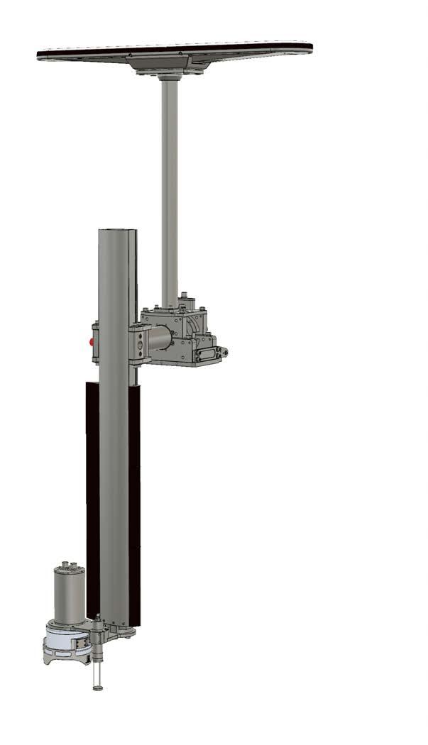
 is used for the M3 Sonar PHS. In the M3 Sonar PHS, the Sonar Head (!) is attached to the bottom of the Pole Mount.")

14 M3 Sonar PHS Operator Manual Sonar Head The Sonar Head includes transmit and receive transducers and the electronics to generate the transmit pulse and digitize the received signal. M3 Sonar Head model number (Ethernet with Sync and 1PPS) is used for the M3 Sonar PHS. In the M3 Sonar PHS, the Sonar Head (!) is attached to the bottom of the Pole Mount. The Sonar Head connects to the M3 Sonar Interface Unit through a head cable with 100Mbps Ethernet and 1PPS time synchronization. Note The M3 Sonar Head s black polyurethane transducer is delicate. Always keep the Guard Ring and protective cover over the transducer during installation and storage. Motion Reference Unit The Motion Reference Unit (MRU) is specially designed for high precision motion measurements in marine applications. The MRU is mounted in a lightweight subsea bottle, rated 10 metres. The MRU cable connects to the M3 Sonar Interface Unit to integrate with Seapath 130 GNSS sensor. The Motion Reference Unit is very sensitive to impacts. Be careful not to drop the MRU. The electronics inside will be damaged and need to be returned to the manufacturer for repair /1.0


15 M3 Sonar PHS Sound speed sensor In order to ensure accurate measurements, a dedicated sound speed sensor is positioned close to the Sonar Head. The sound speed sensor cable connects to the M3 Sonar Interface Unit to output the real-time sound speed to the M3 software. Pole Mount The M3 Sonar PHS Pole Mount provides precise and easy bolt on/off of flanges for all the sensors. Key features: Adjustable and repeatable with no need to re-calibrate Quick to set up and easy to use Safe and audible release of sensor during collision or snag with submerged hazard Adjustable heading and depth with indexing The Pole Mount parts include the following. The GPS Mast for mounting the Seapath 130 sensor unit. The Compact Mount for attaching to your gunwale. The Z Pole and M3 Sonar PHS flange for mounting the Sonar Head, Motion Reference Unit, and sound speed sensor. The X Pole for connecting the Z Pole to the Compact Mount /1.0 13
16 M3 Sonar PHS Operator Manual Support information If you need technical support for your M3 Sonar PHS you must contact your local dealer, or our support department. If you require maintenance or repair, contact your local dealer. You can contact us by phone at , or by at: If you need information about our other products, visit On our website you will also find a list of our dealers and distributors /1.0
17 Getting started Getting started Topics Powering up the M3 Sonar PHS, page 16 Powering down the M3 Sonar PHS, page /1.0 15
18 M3 Sonar PHS Operator Manual Powering up the M3 Sonar PHS Power up the M3 Sonar PHS using the power switch on the M3 Sonar Interface Unit. Prerequisites The M3 Sonar PHS units have all been installed according to the instructions provided in the M3 Sonar PHS Installation Manual. Caution Do not power up the system if the Z-pole is oriented horizontally with the main system units out of the water. Context The M3 Sonar Interface Unit provides power to the following units. Seapath 130 sensor and Motion Reference Unit (MRU) M3 Sonar Head Sound speed sensor The Sonar Processor has its own power adapter. Note It is impossible to control the weather. However, if the vessel has high dynamics during start-up (for example, as a result of rough seas), the Motion Reference Unit (MRU) may run into problems. High dynamics during start-up means that the MRU has moved up to ±10 degrees on all the orientation axes. At worst, the alignment must be redone by restarting the MRU. Procedure 1 Turn on the Sonar Processor. Wait for the operating system to start up. 2 Log in to Windows. 3 Turn on the M3 Sonar Interface Unit to power up most of the system units. Note After powering up, it will take up to 30 minutes for the MRU and the GPS to achieve full accuracy /1.0
19 Getting started Related topics Operating the M3 Sonar PHS, page 37 Powering down the M3 Sonar PHS Power down the M3 Sonar PHS using the power switch on the M3 Sonar Interface Unit. Context When you do not use the M3 Sonar PHS, switch off the entire system. Procedure 1 If you are running the sonar, click Setup Disconnect in the M3 software. 2 Switch off the Sonar Processor. a Save your settings, then close the M3 software and any third-party software. b Shut down Windows. 3 Disconnect the power cord leading to the Sonar Processor power adapter. 4 Switch off the M3 Sonar Interface Unit. 5 Disconnect the power cord leading to the Interface Unit 24-VDC power adapter. 6 Switch off any additional items, such as a display. If required, refer to the instructions provided by the product s manufacturer /1.0 17
20 M3 Sonar PHS Operator Manual Operating procedures Topics Verifying the M3 software settings and starting data export, page 19 Verifying the Hypack software settings and entering offsets, page 26 Verifying the Seapath operator software settings, page 33 Operating the M3 Sonar PHS, page /1.0

21 Operating procedures Verifying the M3 software settings and starting data export If purchased from Kongsberg Mesotech, the M3 Sonar PHS Sonar Processor is configured at the factory prior to delivery. However, before exporting data from the M3 software, make sure that all the settings in the M3 software are correct. Context The M3 software controls the Sonar Head, acquires sounding data, and exports the sounding data to third-party software using the.all format. Third-party software receives the sounding data from the M3 software through UDP with the Kongsberg Mesotech M3 driver. The M3 software can also receive and log the sensor data locally. Procedure 1 Double click the M3 icon on the desktop to run the M3 software. 2 Make sure the profiling settings are set up for a bathymetry application. a b c Select Sonar Apps Profiling - Bathy. If the profiling settings are not visible, click Display Profiling Settings to open the Profiling Settings dialog box. Select Image and Profile in the Profiling Settings dialog box. d e f Set the Algorithm to Split Beam. Set the Point Selection to Strongest. Check the Depth Tracking box to automatically adjust the range according to the current depth. 3 Make sure the exporting format is set to interface with the Hypack software. a b Click File Exporting Format. Select Profile Point (.all). 4 Make sure the M3 software data export settings match the port and IP address used in the Hypack software. a Click Setup Preferences /1.0 19
. The Remote IP Address shown here assumes Hypack is running on the same computer as the M3 software. Click Close.")
22 M3 Sonar PHS Operator Manual b Enter the following values in the UDP Data Export section. c Port for.all format: This UDP port must match the port set in the Hypack software. Remote IP Address: is a loopback address (localhost). The Remote IP Address shown here assumes Hypack is running on the same computer as the M3 software. Click Close. 5 Make sure the Sonar Head has been discovered and is using 1PPS for time synchronization. a b Click Setup System Configuration Devices Sonar Setup. Click Discover Sonar Heads to search for the sonar on the network. c d e If the M3 Sonar Head is found, select it, then click Use Discovered Head. A discovered Sonar Head appears in the Online Sonar Heads list. If the Sonar Head does not appear, the Ethernet connection between the Sonar Processor and Sonar Head has not been established. In the Device Properties table, select 1PPS from the Time Sync Mode drop-down list. Note To use 1PPS, you must send NMEA ZDA to the M3 Sonar on UDP port at 1Hz. Click Close /1.0
 for the Seapath 130 sensor unit with the following device properties.")
23 Operating procedures 6 Make sure the Seapath 130 sensor unit, Motion Reference Unit (MRU), and sound speed sensor are set up as sensor inputs in the software. a Click Setup System Configuration Devices Sensors Setup. b Click Add Device, then set the Protocol GGA (GPS position) for the Seapath 130 sensor unit with the following device properties. Name: Protocol: Port Location: Seapath Position GGA PC UDP Port#: c Click Add Device, then set the Protocol HDT (vessel heading) for the Seapath 130 sensor unit with the following device properties. Name: Protocol: Port Location: Seapath Heading HDT PC UDP Port#: d Click Add Device, then set the Protocol VTG (course and speed) for the Seapath 130 sensor unit with the following device properties. Name: Protocol: Port Location: Seapath Speed VTG PC UDP Port#: /1.0 21
24 M3 Sonar PHS Operator Manual e f g h Click Add Device, then set the Protocol TSS (heave, roll, and pitch) for the Motion Reference Unit (MRU) with the following device properties. Name: Protocol: Port Location: MRU TSS PC UDP Port#: Click Add Device, then set the Protocol Valeport MiniSVS for the sound speed sensor with the following device properties. Name: Protocol: Port Location: Sound Speed Sensor Valeport MiniSVS PC UDP Port#: 4001 Select each sensor device and click the Test Device button. Make sure that the sensor string is being displayed in the Port Monitor box. Note The sound speed sensor string is only visible if the sensor is in the water. i Click Stop Test when done. 7 Make sure the sensors are set up as master references and that the sonar is oriented downwards /1.0

25 Operating procedures a Click Setup System Configuration Deployment Master Reference. b c d e f g h Select Seapath Position from the Position drop-down list. Leave Depth as Fixed. Select Seapath Heading from the Heading drop-down list. Select MRU from the Pitch/Roll and Heave drop-down lists. Select Sound Speed Sensor from the Sound Speed drop-down list. Click Setup System Configuration Deployment Mounting Offsets. Make sure that the X, Y, and Z offsets are all zero /1.0 23

26 M3 Sonar PHS Operator Manual Note In the M3 Sonar PHS, the X (Starboard), Y (Forward), and Z (Vertical) offsets are entered into the Hypack software. i Select Downward for the Orientation parameter. 8 Make sure the sonar view is oriented for a downward-looking bathymetry application. a Click Display Sector Orientation. b Select Enable export of the.all data over UDP for your third-party software. a Open the Hypack software and start a survey. b Open the Menu Widget in the top-right corner of the sonar view. c Click Export Data /1.0
27 Operating procedures A flashing red dot with EXP next to it will appear when exporting profile data. Note You must start a Hypack survey before clicking Export Data. If you have started a survey after exporting data, click Stop Exporting, then click Export Data to re-start the data export /1.0 25
28 M3 Sonar PHS Operator Manual Verifying the Hypack software settings and entering offsets If purchased from Kongsberg Mesotech, the M3 Sonar PHS Sonar Processor is configured at the factory prior to delivery. Before starting a survey, you can test if data is being received from the M3 software and from your Seapath 130 sensor and Motion Reference Unit (MRU). Prerequisites You must have configured the M3 software to export data to third-party software. Insert the Hypack software dongle into a USB port on the Sonar Processor before running Hypack. You must measure the distance (in metres) between the waterline and the M3 Sonar transducer (positive downward). You will need to enter this static draft value into the Hypack software as the Vertical (Z) offset. Procedure 1 Double click the Hypack icon on the desktop to run the Hypack software. 2 Click Preparation Hardware Setup. Observe that the HYPACK Combined Hardware dialog box opens. 3 Make sure that GPS settings are correct. a On the left side of the HYPACK Combined Hardware dialog box, click on the GPS NMEA-0183 entry under Boat. Note This driver provides Position (GGA), Heading (HDT), and Time (ZDA). b Select the Survey Connect tab /1.0

29 Operating procedures c Make sure that the Device Connection field appears as shown. The factory-configured Seapath output is on UDP port d e f g h Click Test Device. The Test window will open. Make sure that GPS data is being received. Close the Test window. Select the Offsets tab. Enter the static draft distance you measured earlier into the Vertical text box /1.0 27

30 M3 Sonar PHS Operator Manual Note The GPS antenna location (position data output point) is pre-programmed into the Seapath 130 sensor unit at the factory. This location is based on using the centre of the M3 Sonar transducer face as the reference point and on using a standard Pole Mount height. If you have adjusted the height of the Pole Mount (or are using your own Pole Mount for deployment) you will need to change these offsets in the Seapath operator software. 4 Make sure that the Motion Reference Unit (MRU) settings are correct. a On the left side of the HYPACK Combined Hardware dialog box, click on the Kongsberg Seapath (Network) entry under HYSWEEP Survey. Note This driver provides Pitch, Roll, and Heave information through the Seapath BIN 26 format. b c Select the Connect tab. Make sure that the Port value is set to (the factory-configured default). d Select the Offsets tab /1.0
31 Operating procedures e Enter the static draft distance you measured earlier into the Vertical text box. Note The MRU location (motion data output point) is pre-programmed into the Seapath 130 sensor unit at the factory. This location is based on using the centre of the M3 Sonar transducer face as the reference point and on using a standard Pole Mount height. If you have adjusted the height of the Pole Mount (or are using your own Pole Mount for deployment) you will need to change these offsets in the Seapath operator software. 5 Make sure that the M3 Sonar settings are correct. a b c d On the left side of the HYPACK Combined Hardware dialog box, click on the Kongsberg Mesotech M3 entry under HYSWEEP Survey. Select the Manufacturer / Model tab. Click the Setup button. Observe that the Simrad Setup dialog box opens. Make sure that Use Raw Data is selected. e f Click OK to close the dialog box. Select the Connect tab /1.0 29
32 M3 Sonar PHS Operator Manual g Make sure that the Port value is set to and that the Internet Address is set to (the factory-configured default). Note These network settings must match the UDP Data Export settings configured in the M3 software is a loopback address (localhost). This address assumes Hypack is running on the same computer as the M3 software. h i j k Click Network Test. Observe that the Network Connection dialog box opens. Click UDP Connect to confirm that data is being received from the M3 software. Note This network test will only work if data export has been enabled in the M3 software. Click Close to close the Network Connection dialog box. Select the Offsets tab /1.0

33 Operating procedures l Enter the static draft distance you measured earlier into the Vertical text box. 6 Make sure the clock is synchronized to the GPS. a b On the left side of the HYPACK Combined Hardware dialog box, click on Hardware. Make sure that GPS NMEA-0183 is selected in the Select Device to Synchronize Clock drop-down list. 7 Close the HYPACK Combined Hardware dialog box. 8 Make sure the correct drivers have been selected for HYSWEEP surveys /1.0 31
34 M3 Sonar PHS Operator Manual a b c Click Survey HYPACK Survey and HYSWEEP Survey. In the HYSWEEP Survey window, click View Device Selections. Observe that the Device Selections dialog box opens. Select the Select Boat Corrections tab. d e f For Heading, select Hypack Navigation from the drop-down list. For Heave and Pitch / Roll, select Kongsberg Seapath (Network) from the drop-down lists. Click OK /1.0
35 Operating procedures Verifying the Seapath operator software settings Offsets are pre-programmed into the Seapath 130 sensor unit at the factory. These offsets are based on using the centre of the M3 Sonar transducer face as the reference point and on using a standard Pole Mount height. If you have adjusted the height of the Pole Mount (or are using your own Pole Mount for deployment) you will need to change these offsets in the Seapath operator software. Context When you review the offsets in the Seapath operator software, keep the following definitions in mind. Navigation Reference Point (NRP): The NRP is the reference point for all measurements in the system. The recommended NRP is near the Centre of Gravity (CG), but can be chosen freely. It is always defined related to the Survey origin. In the default M3 Sonar PHS configuration, the X, Y, and Z coordinates of the NRP are all set to zero, so that the NRP is set to the same point as the Survey origin. Survey origin: the origin of the survey data. In the default M3 Sonar PHS configuration, the Survey origin is set to the centre of the M3 Sonar transducer. Note If you need to make changes in the Seapath operator software, click the Apply button to save the changes. Procedure 1 Double click the Seapath HMI icon on the desktop to start the Seapath operator software. 2 Select System Change system mode Configuration. Observe that the Change system mode dialog box opens. 3 Type the password stx, then click OK. This password is not case sensitive. You are now able to carry out changes and/or set system parameters. 4 Select System NAV Engine Standard. Observe that the NAV Engine Configuration dialog box opens /1.0 33
, and at the same level of the keel.")
36 M3 Sonar PHS Operator Manual 5 Make sure that the Vessel Geometry settings are correct. a On the left side of the dialog box, select Vessel Geometry. b Make sure the Survey origin offsets are as shown. c The M3 Sonar is mounted three metres from the stern, metres from the centre line (positive starboard), and at the same level of the keel. Make sure that the Navigation reference point (NRP) offsets are all set to zero /1.0
 offsets are as shown. The Seapath 130 sensor unit is mounted 0.266 metres behind the M3 Sonar, 0.")
37 Operating procedures 6 Make sure that the GNSS Geometry settings are correct. a On the left side of the dialog box, select GNSS Geometry. b Make sure the Antenna location (from Survey origin) offsets are as shown. The Seapath 130 sensor unit is mounted metres behind the M3 Sonar, metres to the port side of the M3 Sonar, and 2.57 metres above the M3 Sonar /1.0 35
 offsets are as shown. c The MRU is mounted 0.116 metres above the M3 Sonar. The MRU is located at the same X and Y coordinates as the M3 Sonar.")
38 M3 Sonar PHS Operator Manual 7 Make sure that the Motion Reference Unit (MRU) Geometry settings are correct. a On the left side of the dialog box, select MRU Geometry. b Make sure the Sensor location (from Origin) offsets are as shown. c The MRU is mounted metres above the M3 Sonar. The MRU is located at the same X and Y coordinates as the M3 Sonar. Make sure that the Mounting angles are as shown. Tip You can click the Mounting Wizard button to set the angles so that they match the physical installation of the MRU. Make sure the +X arrow on the housing points to starboard. 8 Close the Seapath operator software /1.0
39 Operating procedures Operating the M3 Sonar PHS The M3 Sonar PHS supports Hypack as a suitable third-party acquisition software for performing bathymetry surveys. Prerequisites The M3 Sonar PHS units have all been installed according to the instructions provided in the M3 Sonar PHS Installation Manual. The Seapath 130 sensor unit must be mounted horizontally on the Pole Mount with the primary antenna (position reference point) pointing towards the stern. The Motion Reference Unit (MRU) must be mounted with the Y arrow indication on top of the MRU housing pointing towards the bow. The M3 Sonar Head must be mounted with the connector pointing towards the bow. Make sure that the required software packages have been installed on your Sonar Processor, including the Seapath Operator Software, M3 software, and third-party acquisition software. Make sure that the Pole Mount is oriented in a vertical position. Caution Do not power up the system if the Z-pole is oriented horizontally with the main system units out of the water. Context The recommended survey vessel speed is five knots (2.5 m/s). When running survey lines, the suggested line spacing is <= 3 x water depth. Perform a sound velocity profile (SVP) cast as often as possible or if the error is greater than 2.5 m/s when compared with the real-time sound speed measured at the transducer. Note It will take up to 30 minutes for the Seapath 130 sensor unit to achieve full accuracy after power up. As there is normally no reason to power down the Seapath 130 sensor unit, it can be left running continuously. You do not have to use the Seapath operator software to start data export. The Seapath 130 sensor unit outputs signals on the serial lines and Ethernet ports automatically /1.0 37

 from the drop-down lists. Click OK. 5 Wait for the NO SYNC yellow status to appear.")
40 M3 Sonar PHS Operator Manual Procedure 1 Power up the hardware. 2 Double click the Hypack icon on the desktop to run the Hypack software. 3 Click Survey HYPACK Survey and HYSWEEP Survey. 4 Make sure the correct drivers have been selected for HYSWEEP surveys. a b In the HYSWEEP Survey window, click View Device Selections. Observe that the Device Selections dialog box opens. Select the Select Boat Corrections tab. c d e For Heading, select Hypack Navigation from the drop-down list. For Heave and Pitch / Roll, select Kongsberg Seapath (Network) from the drop-down lists. Click OK. 5 Wait for the NO SYNC yellow status to appear. 6 Wait another 30 seconds while the Hypack software synchronizes the computer clock with the GPS /1.0

41 Operating procedures 7 Double click the M3 icon on the desktop to run the M3 software. 8 Start exporting data to Hypack. a Open the Menu Widget in the top-right corner of the sonar view. b Click Export Data. A flashing red dot with EXP next to it will appear when exporting profile data. Note You must start a Hypack survey before clicking Export Data. If you have started a survey after exporting data, click Stop Exporting, then click Export Data to re-start the data export /1.0 39
42 M3 Sonar PHS Operator Manual 9 Perform a patch test. a b c d Record Latency calibration data. 1 Select one survey line with a feature like a wreck, rock outcrop, or slope. 2 Run the survey line in the same direction at one speed. 3 Run the same survey line in the same direction at twice the speed of the first run. Record Roll calibration data. 1 Select one survey line on a flat sea floor with a depth of 30 meters or deepest available area. 2 Run the survey line at the same speed in the opposite direction. 3 Record a second set of lines to obtain a redundant data set. Record Pitch calibration data. 1 Select one line on a sloped seafloor. 2 Run the survey line at the same speed in the opposite direction. 3 Record a second set of lines to obtain a redundant data set. Record Yaw calibration data. 1 Select two lines offset by half the swath width. The overlap of the two runs should cover an object such as a wreck, rock outcrop, pipeline, or trench line. 2 Run both lines in the same direction and at the same survey speed. 3 Record a second set of lines to obtain a redundant data set. Related topics Powering up the M3 Sonar PHS, page /1.0
43 Operating procedures Performing a beam angle test The beam angle test compares multibeam check lines to a reference surface and estimates the depth accuracy of the multibeam system at different angle limits. The estimated accuracy can be used to determine if the multibeam system meets survey specifications. Prerequisites Before performing a beam angle test, you need to create a reference surface. To create the reference surface, run a test survey over a small area with a very flat, uniform bottom. Run the survey at low or high tide to decrease potential for errors due to changing tide or water conditions. Perform a Sound Velocity Profile (SVP) cast immediately before the survey. Use lots of overlap and area of nadir depths (in processing) to get the best possible estimation of depth. Survey two sets of seven parallel lines, crossing at 90 degrees, with the separation of the lines equal to the water depth. Reference the matrix file (.MTX) with 1 x 1 (30 cm) cells. Survey the reference lines first. Then survey the check lines: middle lines NS and EW. Do not use one of the reference lines! Save the reference survey to XYZ format. Procedure 1 Use the same user-defined.mtx file that you used when creating the reference surface. a b Select Preparation Editors Matrix Editor. Click File Open to open your.mtx file /1.0 41

44 M3 Sonar PHS Operator Manual 2 Load check survey data into MBMAX64. a Select HYSWEEP HYSWEEP Editor (64 bit). b Select File Load Survey to open your survey. 3 Edit minimally, removing outliers. Do not use angle limits so that statistics for all available beams are generated. 4 Start the beam angle test. a In the MBMAX64 window, click Tools Beam Angle Test. Note Use your reference matrix file in the last stage of editing (stage 2). b Select the reference surface (the XYZ file you created earlier) to which you will compare the check lines, then click OK /1.0
.")
45 Operating procedures 5 Check the test result. The X axis is the beam angle. The Y axis is the depth difference. The x s in the graph show biases. The o s in the graph show repeatability (maximum difference at 95 percent confidence) /1.0 43
46 M3 Sonar PHS Operator Manual Preventive maintenance Seapath 130 and MRU maintenance Seatex units are not designed for service in the field. All repairs and modifications of these units must be carried out by qualified personnel. Units in need of repair or service must be shipped back to Kongsberg Seatex AS (or other agreed service point) in the original transportation box. Caution Opening the housing will result in damage or degradation of the unit and void the warranty. The Motion Reference Unit (MRU) may need to be periodically recalibrated, depending on the MRU model and the application in which it is used. In general the following is recommended. MRU H A recalibration is recommended every fourth year. MRU 3 A recalibration is recommended every second year /1.0
47 Preventive maintenance Troubleshooting Symptom: Reduced roll or pitch performance. Probable cause The MRU is misaligned, or incorrect offsets are being used in the software. It has been several years since the MRU was last calibrated. Corrective Action Make sure that the Y arrow on top of the MRU housing is properly aligned with the ship's longitudinal axis. A misalignment of only one degree will reduce the performance when exposed to heavy motion due to cross-coupled roll and pitch measurements. If not already done, make sure that the MRU yaw offset according to the ship's longitudinal axis is accurately measured and entered into the Seapath operator software. Contact Kongsberg Seatex AS to check whether the MRU needs recalibration. Symptom: Reduced heading performance. Probable cause There is a problem with the Motion Reference Unit (MRU). The antenna baseline has not been properly calibrated. The Seapath 130 sensor unit is not receiving data from GNSS receiver No. 1 or 2. Corrective Action Troubleshoot the MRU, as described above. Run the Seapath operator software and make sure that the antenna baseline setup parameters in NAV Engine Configuration Sensors GNSS Geometry are properly configured. If needed, perform a new calibration of the antenna baseline. Run the Seapath operator software and make sure that data appears in the Port Monitor in the Tools menu and by selecting GNSSA1 for GNSS antenna No. 1 and GNSSB1 for antenna No. 2. If you still cannot see any data, perform a receiver reset by selecting System Restart GNSS receiver. Symptom: Reduced position/velocity performance. Probable cause No differential corrections are input on the GNSS serial cable of the sensor unit. The vessel is out of range to a radio reference station and the differential corrections are therefore missing. The antenna or the MRU offset setup is incorrect. Corrective Action Run the Seapath operator software and check that the link for differential corrections is properly set up in the DgnssLink configuration, part of the Input/Output subfolder in the NavEngine configuration. Run the Seapath operator software, then select Tools DGNSS Monitor to view the location of the reference stations connected to the Seapath 130 sensor unit. If the reference station is too far away or is in the shadow of geographical obstructions or other equipment on board, reception may be unreliable or missing. Check the setup of the lever arms from the Navigation Reference Point (NRP) to antenna #1 and to the MRU. Check particularly that the sign for each of the vector components are correct by entering the Geometry subfolder under Sensor GNSS MRU in the NavEngine configuration /1.0 45
48 M3 Sonar PHS Operator Manual Symptom: No data is being received from the Seapath 130 sensor unit. Probable cause The Seapath 130 sensor unit is powered down. Your PC is on a different network from the Seapath 130 sensor unit. Corrective Action Check the power connection to the unit. Check that the PC with the software is configured to the same subnet as the Seapath 130 sensor unit. Tip For more detailed troubleshooting information, see the Seapath 130 series Operator manual. Updating the Seapath 130 sensor unit firmware We recommend that you keep your product updated with the latest firmware version. Prerequisites The default IP address for the sensor unit is: Procedure 1 Open a browser and type into the address bar. 2 Type the default login credentials: User name: scompact Password: 1234 The user name is case sensitive. 3 Enter the Configuration management and select Update SW. 4 Select the provided update package zip file. 5 Select Upload and wait up to 10 seconds for the file to be transferred. 6 Select Install. Result The unit will then start to unpack the update package. The update process can take up to one minute. If the update was successful, the unit will restart. The installation results will show Installation successful together with a detailed report /1.0
49 Preventive maintenance Should the update be unsuccessful, try again and contact Kongsberg Seatex AS customer support. Valeport minisvs maintenance According to the manufacturer, in the majority of cases, performance can be maintained by recalibrating at two-year intervals. Troubleshooting Symptom: The M3 software is not receiving data from the minisvs sound speed sensor. Probable cause The sound speed sensor is not powered up. The sound speed sensor is not in the water. Corrective Action Check the power connection to the unit. Deploy the sensor underwater. The sound speed sensor only outputs data if the sensor is in the water. M3 Sonar maintenance The M3 Sonar offered in the M3 Sonar PHS standard package (with aluminium housing) is not suitable for long-term deployment. Consult the factory for alternative housing materials if you require long-term deployment. Caution The M3 Sonar Head s black polyurethane transducer is delicate. Always keep the Guard Ring and protective cover over the transducer during installation and storage. All units and parts must be rinsed with fresh water and dried off before packing away. All cables must be disconnected and protective dust caps placed on all connectors /1.0 47
50 M3 Sonar PHS Operator Manual Troubleshooting Symptom: The M3 Sonar is not being detected in the M3 software. Probable cause The unit is not powered up. Your PC is on a different network from the M3 Sonar. There is no physical connection to the Sonar Head. Corrective Action Make sure that the M3 Sonar Interface Unit is powered up. Check that the PC with the software is configured to the same subnet as the M3 Sonar. Make sure that the Ethernet cable connects to the PC running the M3 software. Symptom: The M3 Sonar has a slow ping rate. Probable cause The communication link is of poor quality, or cable(s) are improperly terminated. There is a marginal telemetry link (or interference with the link). A problematic telemetry link can cause packet loss or reduced Ethernet bandwidth. This marginal telemetry link causes the M3 software to lower the ping rate because it has measured the available network bandwidth and reduced the ping rate accordingly. Corrective Action Check the Ethernet link between your computer and the Sonar Head. Test the cables with a suitable Ethernet tester, such as the Fluke CableIQTM Ethernet Cable Qualification Tester (CIQ-100). Connect a 50-foot test cable between the Sonar Head and Sonar Processor to rule out a problem with your cables, fiber optic to Ethernet media converters, or Sonar Head and Sonar Processor. If the problem still persists, you can perform a work-around by overriding the network link speed. 1) Click Setup System Configuration in the M3 software. 2) Check the Override Network Link Speed box and enter 125 into the Mbps field to set an override value. If the problem persists or if pings are missing in your recorded data, reduce the override value. Tip For more detailed troubleshooting information, see the M3 Sonar Maintenance Manual /1.0
51 Preventive maintenance Pole Mount maintenance In order to protect the equipment, the Pole Mount includes shear blocks that are designed to break under excessive speed or if the Pole Mount hits an obstacle. To replace a broken shear block, remove the shear block assembly, loosen the Allen bolts until the old block releases, then replace the shear block. Make sure that all stainless Pole Mount hardware is always coated with a marine-grade anti-seize product, such as "Never Seez". Always wash and dry the Pole mount after each use. After the unit is dry, apply a silicone spray or a lubricant that does not make plastic swell, such as BoeshieldT /1.0 49
52 M3 Sonar PHS Operator Manual Index A about comments... 6 constructive criticism... 6 feedback... 6 purpose of this manual... 5 registered trademarks... 5 software license... 5 software version... 5 suggestions... 6 target audience... 5 audience this manual... 5 H how to export data operate M3 Sonar PHS power off power up update Seapath 130 sensor unit firmware verify M3 software settings verify the Seapath operator software settings Hypack beam angle test measuring device offsets verifying data B block diagram... 9 book purpose... 5 target audience... 5 C comments send us... 6 constructive criticism send us... 6 D data exporting description preventive maintenance system... 8 drawing system diagram... 9 E exporting data F features key... 8 feedback send us... 6 functional diagram... 9 I information support Interface Unit introduction...11 overview...11 purpose...11 introduction Interface Unit...11 Motion Reference Unit (MRU) Pole Mount Seapath 130 sensor unit...11 Sonar Head Sonar Processor...11 sound speed sensor K key features system... 8 Kongsberg Mesotech support L license software... 5 M M3 software settings verifying M3 Sonar PHS operating maintenance Motion Reference Unit (MRU) Pole Mount preventive /1.0
53 Index Seapath 130 sensor unit Sonar Head sound speed sensor manual purpose... 5 target audience... 5 measure device offsets how to measuring device offsets procedure Motion Reference Unit (MRU) introduction maintenance overview purpose troubleshooting MRU introduction overview purpose O off power office support on power operating M3 Sonar PHS overview Interface Unit...11 Motion Reference Unit (MRU) Pole Mount Seapath 130 sensor unit...11 Sonar Head Sonar Processor...11 sound speed sensor P perform a beam angle test how to performing a beam angle test procedure Pole Mount introduction maintenance overview purpose power off on preventive maintenance procedures procedure exporting data operating M3 Sonar PHS powering off powering up verifying M3 software settings verifying the Seapath operator software settings procedures preventive maintenance publication purpose... 5 target audience... 5 purpose Interface Unit...11 Motion Reference Unit (MRU) Pole Mount Seapath 130 sensor unit...11 Sonar Head Sonar Processor...11 sound speed sensor this manual... 5 R reader this manual... 5 registered trademarks... 5 S Seapath 130 sensor unit how to update firmware introduction...11 maintenance overview...11 purpose...11 troubleshooting Seapath operator software settings verifying software license... 5 version... 5 Sonar Head introduction maintenance overview purpose troubleshooting Sonar Processor introduction...11 overview...11 purpose...11 sound speed sensor introduction maintenance overview purpose suggestions send us... 6 support information switch off on /1.0 51
54 M3 Sonar PHS Operator Manual system description... 8 diagram... 9 key features... 8 T target audience this manual... 5 this manual purpose... 5 target audience... 5 trademarks registered... 5 troubleshooting Motion Reference Unit (MRU) Seapath 130 sensor unit Sonar Head U updating Seapath 130 sensor unit firmware V verify data in Hypack how to verifying M3 software settings Seapath operator software settings verifying data in Hypack procedure version software /1.0
55
56 2018 Kongsberg Mesotech
Operator Manual. MS1000 Software. Trencher Monitoring System
 Operator Manual MS1000 Software Trencher Monitoring System MS1000 Software Trencher Monitoring System Operator Manual Release 1.2 This manual provides you with the basic information required to operate
Perspective-MB. -- Bathymetry Processing Guide. Kongsberg.ALL Addendum
 Perspective-MB -- Bathymetry Processing Guide Kongsberg.ALL Addendum By: Tony M. Ramirez November, 2013 Triton Imaging Inc. Engineering Office 2121 41 st Avenue, Suite 211 Capitola, CA 95010 USA +1-831-722-7373
Reference Manual. M3 Sonar. Multibeam Sonar
 Reference Manual M3 Sonar Multibeam Sonar M3 Sonar Multibeam sonar Reference Manual Release 1.3 This manual provides you with reference information required to operate and fully understand the commands,
Maintenance Manual. M3 Sonar. Multibeam Sonar
 Maintenance Manual M3 Sonar Multibeam Sonar M3 Sonar Multibeam sonar Maintenance Manual Release 1.1 The purpose of this manual is to present the descriptions and drawings required to do basic maintenance
Checking the values using backscatter data
 A Technique for using Backscatter Imagery to Calibrate your Multibeam sonar Harold Orlinsky Harold@Hypack.com Checking the values using backscatter data The collection of Backscatter is co located with
Simrad EK80. Software Release Note Introduction
 Simrad EK80 Software Release Note 1.12.2 Introduction This document describes the changes introduced with the new software version. Product: EK80 Software version: 1.12.2 This software controls all functionality
Gemini Profiler with Survey Software
 0695-SOM-00008, Issue: 02 1 Tritech International Ltd. QPS QINSy 0695-SOM-00008, Issue: 02 Tritech International Ltd The copyright in this document is the property of Tritech International Ltd. The document
The Results of Limiting MRU Updates In Multibeam Data by Pat Sanders, HYPACK, Inc.
 The Results of Limiting MRU Updates In Multibeam Data by Pat Sanders, HYPACK, Inc. Abstract: Some Motion Reference Units (MRUs) can deliver heave- pitch- roll data at rates up to 100Hz. This paper investigates
Teledyne PDS. Multibeam Calibration. Version January Teledyne RESON B.V. Stuttgartstraat AS Rotterdam The Netherlands
 Multibeam Calibration Teledyne PDS Version 2.0.4 January 2017 Teledyne RESON B.V. Stuttgartstraat 42-44 3047 AS Rotterdam The Netherlands Tel.: +31 (0)10 245 15 00 www.teledyne-reson.com Teledyne RESON
Simrad EK80. Software Release Note Introduction
 Simrad EK80 Software Release Note 1.12.1 Introduction This document describes the changes introduced with the new software version. Product: EK80 Software version: 1.12.1 This software controls all functionality
Quick Start: GeoDAS-LT with Single Beam Echo Sounder
 Quick Start: GeoDAS-LT with Single Beam Echo Sounder I. Setting up GeoDAS-LT for Single Beam Echo Sounder Survey 1. Connect your single beam echo sounder, GPS receiver and other sensors (e.g. gyro and
Hysweep Survey Interfacing Notes
 Hysweep Survey Interfacing Notes Table of Contents: Table of Contents:...1 Update History:...3 Analog Sidescan...4 Applanix POS/MV Network...5 Applanix POS/MV Serial...8 Atlas Bomasweep...9 Atlas Fansweep
GEOACOUSTICS GEOSWATH PLUS DATA PROCESSING WITH CARIS HIPS 8.1
 GEOACOUSTICS GEOSWATH PLUS DATA PROCESSING WITH CARIS HIPS 8.1 IN SUPPORT OF SANDY SUPPLEMENTAL RESEARCH Val Schmidt and Kevin Jerram University of New Hampshire Center for Coastal and Ocean Mapping Sunken
SHALLOW SOUNDING BATHYMETRIC USING MULTIBEAM ECHOSOUNDER AND TOPOGRAPHIC LASER SCANNER
 SHALLOW SOUNDING BATHYMETRIC USING MULTIBEAM ECHOSOUNDER AND TOPOGRAPHIC LASER SCANNER BY : NURSUGI, TRI PATMASARI & KHAFID GEOSPASIAL INFORMATION AGENCY AMSTERDAM, 11-14 NOVEMBER 2014 Indonesia coastline
APN-078: Configuring SPAN for Hydrographic Applications in OEM7
 APN-078: Configuring SPAN for Hydrographic Applications in OEM7 1 Table of Contents 1 Overview... 3 2 ALIGN Calibration... 4 2.1 ALIGN Calibration Procedure... 5 4. SPAN Configuration for Hydrographic
Teledyne PDS. Cutter Dredge. Version March Teledyne RESON B.V. Stuttgartstraat AS Rotterdam The Netherlands
 Cutter Dredge Teledyne PDS Version 2.1.1 March 2017 Teledyne RESON B.V. Stuttgartstraat 42-44 3047 AS Rotterdam The Netherlands Tel.: +31 (0)10 245 15 00 www.teledyne-reson.com Teledyne RESON has made
Patch Test & Stability Check Report
 Patch Test & Stability Check Report Storebælt, 2009 SB Cable Project CT Offshore Final Report November, 2009 SB Cable Project November 2009 8-10 Teglbaekvej DK-8361 Hasselager Aarhus, Denmark Tel: +45
Manual on Wobble Analysis
 Manual on Wobble Analysis In Swathed Index Index...2 Introduction...3 0.1 Recognize Artefacts...5 0.2 Unravel the data...6 0.3 Make a DTM...8 0.4 Open the data...8 1 Swath editor...10 1.1 Introduction...10
Indoor Mini Dome. Hardware Manual D91, D92, E91, E92. Ver. 2013/06/14
 Indoor Mini Dome Hardware Manual D91, D92, E91, E92 Ver. 2013/06/14 Table of Contents Precautions 3 Safety Instructions... 5 Introduction 6 List of Models... 6 Package Contents... 7 Physical description...
Manual Version: V1.00. Video Decoder User Manual
 Manual Version: V1.00 Video Decoder User Manual Thank you for purchasing our product. If there are any questions, or requests, please do not hesitate to contact the dealer. Copyright Copyright 2016 Zhejiang
Encoder Firmware V User s Manual. Outdoor PTZ Camera Hardware Manual KCM /05/09.
 Encoder Firmware V4.06.09 User s Manual Outdoor PTZ Camera Hardware Manual KCM-8211 2013/05/09 1 Table of Contents Precautions... 3 Introduction... 4 List of Models... 4 Package Contents... 5 Safety Instructions...
SVP Manager Installation Manual
 SVP Manager Installation Manual This manual describes how to install the SVP Manager. 318213/A Jan 2008 Document history Document number: 318213 Rev. A January 2008 First version. The reader This operator
Operator Manual SIS. Seafloor Information System
 Operator Manual SIS Seafloor Information System Seafloor Information System SIS Operator Manual Release 3.6 164709/G September 2009 Document history Document number: 164709 Rev. F April 2007 Operator
Hook2 X Series. Operator Manual. 4x GPS, 4x Sonar, 5x GPS HDI, 7x GPS HDI ENGLISH
 Hook2 X Series Operator Manual 4x GPS, 4x Sonar, 5x GPS HDI, 7x GPS HDI ENGLISH www.lowrance.com Preface Disclaimer As Navico is continuously improving this product, we retain the right to make changes
Teledyne PDS. Trailing Suction Hopper. Version April Teledyne RESON B.V. Stuttgartstraat AS Rotterdam The Netherlands
 Trailing Suction Hopper Teledyne PDS Version 1.1.0 April 2017 Teledyne RESON B.V. Stuttgartstraat 42-44 3047 AS Rotterdam The Netherlands Tel.: +31 (0)10 245 15 00 www.teledyne-reson.com Teledyne RESON
Operator manual Simrad SX90 Fish finding sonar
 Operator manual Simrad SX90 Fish finding sonar www.simrad.com T E C H N O L O G Y F O R S U S T A I N A B L E F I S H E R I E S Simrad SX90 Operator manual This manual provides you with the basic information
Transducer and LBL calibration - Integrated functions in HiPAP systems
 Transducer and LBL calibration - Integrated functions in HiPAP systems Dynamic Positioning Conference, Houston, September 17-18 2002 arranged by 1 Calibration of transducer alignment and of LBL array This
HiPAP. Software release notes. Release (XP)/Release (Win7/XP)
/Release (Win7/XP)") HiPAP Software release notes Release 2.15.4 (XP)/Release 3.5.4 Added support for HiPAP 200. In an LBL array, when reply from one transponder was missing, no LBL position was computed and no telegram sent
HiPAP Software release notes Release 2.15.4 (XP)/Release 3.5.4 Added support for HiPAP 200. In an LBL array, when reply from one transponder was missing, no LBL position was computed and no telegram sent
SeaBat T50-P Product Description
 SeaBat T50-P Ultra-High Resolution Multibeam Echosounder December 2015 Table of Contents System Overview... 4 Introduction... 4 Typical Applications... 4 Warranty... 4 System Architecture... 5 SeaBat T50-P...
User Manual PUH4-H2. 4K HDMI Splitter 1x4. All Rights Reserved. Version: PUH4-H2_2016V1.2
 User Manual PUH4-H2 All Rights Reserved Version: PUH4-H2_2016V1.2 Preface Read this user manual carefully before using this product. Pictures shown in this manual is for reference only, different model
WinRiver Quick Start Guide
 WinRiver Quick Start Guide P/N 957-6203-00 (October 2003) RD Instruments Acoustic Doppler Solutions Table of Contents... 1 Introduction...1 Overview...1 Hardware Overview...2 ADCP Requirements...2 ADCP
Simrad TD50 3D Visualisation software
 Simrad TD50 3D Visualisation software Reference Manual Release 1.3.x The purpose of this manual is to provide the descriptions and procedures required to allow for efficient use of the Simrad TD50. The
Users Manual OPN Pocket Memory Scanner
 Users Manual OPN 2001 Pocket Memory Scanner CAUTION: This user s manual may be revised or withdrawn at any time without prior notice. Copyright 2006 Opticon Sensors Europe B.V. All rights reserved. This
NAVIPAC/NAVISCAN WITH EDGETECH 6205
 NAVIPAC/NAVISCAN WITH EDGETECH 6205 Last update: 19/11/2015 Version: 1.0 Contents 1 Scope of the document... 3 2 NaviScan Configuration... 3 2.1 Configuring the instruments from EdgeTech... 3 2.1.1 Configuring
Fixed Network Camera Hardware User Manual
 Fixed Network Camera Hardware User Manual FCS-0032 Ver. 2013/12/04 Table of Contents Precautions 3 Safety Instructions... 5 Introduction 6 List of Models... 6 Package Contents... 6 Physical Description...
Author s Name Name of the Paper Session. DYNAMIC POSITIONING CONFERENCE October 12-13, 2010 SENSORS SESSION
 Author s Name Name of the Paper Session DYNAMIC POSITIONING CONFERENCE October 12-13, 21 SENSORS SESSION and accurate transformation of acceleration over long lever arms on large vessels method, test results
CARIS HIPS & SIPS 8.0 Manual
 MGEO 2014 CARIS HIPS & SIPS 8.0 Manual For Hydrography & Survey Use. 0 Tiffany Schnare www.geo-tiff.com MGEO 2014 Brian Pyke May 30, 2013 Foreward The following document was produced with the Marine Geomatics
360 Imaging Installation Guide
 360 Imaging Installation Guide 532050-1_C Thank You! Thank you for choosing Humminbird, the #1 name in Fishfinders. Humminbird has built its reputation by designing and manufacturing top-quality, thoroughly
Prepared for: CALIFORNIA COAST COMMISSION c/o Dr. Stephen Schroeter 45 Fremont Street, Suite 2000 San Francisco, CA
 REVIEW OF MULTIBEAM SONAR SURVEYS WHEELER REEF NORTH, SAN CLEMENTE, CALIFORNIA TO EVALUATE ACCURACY AND PRECISION OF REEF FOOTPRINT DETERMINATIONS AND CHANGES BETWEEN 2008 AND 2009 SURVEYS Prepared for:
Vector Compact-S (NMEA 0183) Vector Compact-N (NMEA 2000) Quick Installation Guide
 Vector Compact-N (NMEA 2000) Quick Installation Guide") Vector Compact-S (NMEA 0183) Vector Compact-N (NMEA 2000) Quick Installation Guide Seapilot VECTOR COMPACT-S NMEA 0183 (Serial) Kit Housing Screw Caps and O-ring Housing M6 Screws Mounting Base Front View
Vector Compact-S (NMEA 0183) Vector Compact-N (NMEA 2000) Quick Installation Guide Seapilot VECTOR COMPACT-S NMEA 0183 (Serial) Kit Housing Screw Caps and O-ring Housing M6 Screws Mounting Base Front View
trimble r10 GNSS System
 TRIMBLE R10 SERIES RECEIVER QUICK START GUIDE trimble r10 GNSS System C Warning: For safety information, refer to the Safety Information section of the Trimble R10 GNSS Receiver User Guide. Five simple
R1 Extender. Quick Installation Guide
 R1 Extender Quick Installation Guide V1.0 January 2009 Copyright Copyright 2008 all rights reserved. No part of this publication may be reproduced, adapted, stored in a retrieval system, translated into
Cube Camera with Fixed Lens Hardware Manual D11, D12. Ver. 2013/05/17
 Cube Camera with Fixed Lens D11, D12 Ver. 2013/05/17 Table of Contents Precautions 3 Safety Instructions... 5 Introduction 6 List of Models... 6 Features and Benefits... 7 Package Contents... 8 Physical
TABLE OF CONTENTS TABLE OF CONTENTS... 1 MANUAL REVISION HISTORY... 2 IMPORTANT SAFETY NOTICE...
 TABLE OF CONTENTS TABLE OF CONTENTS... 1 MANUAL REVISION HISTORY... 2 IMPORTANT SAFETY NOTICE... 3 1.0 General Information... 5 1.1 System Components... 5 1.2 Specifications... 5 1.2.1 Torque Ranges...
DYNAMIC POSITIONING CONFERENCE September 16-17, Sensors
 DYNAMIC POSITIONING CONFERENCE September 16-17, 2003 Sensors An Integrated acoustic positioning and inertial navigation system Jan Erik Faugstadmo, Hans Petter Jacobsen Kongsberg Simrad, Norway Revisions
SERIES 4600 Ethernet Visual-Pager Display INSTALLATION and SPECIFICATION GUIDE. Manual No. D Revision Date: 08/2016 Control: 1.
 SERIES 4600 Ethernet Visual-Pager Display INSTALLATION and SPECIFICATION GUIDE Manual No. D4600-7010 Revision Date: 08/2016 Control: 1.0 Microframe Corporation 604 South 12th Street Local: 918-258-4839
Handout. and. brief description. Marine Gravity Meter KSS 32- M
 and brief description of Marine Gravity Meter KSS 32- M Copyright 1999-2010 Bodensee Gravitymeter Geosystem GmbH All rights reserved 1 KSS32-M Marine Gravity Meter Cover removed Copyright 1999-2010 Bodensee
SC-T35/SC-T45/SC-T46/SC-T47 ViewSonic Device Manager User Guide
 SC-T35/SC-T45/SC-T46/SC-T47 ViewSonic Device Manager User Guide Copyright and Trademark Statements 2014 ViewSonic Computer Corp. All rights reserved. This document contains proprietary information that
Assembly Manual & User Guide
 Assembly Manual & User Guide TABLE OF CONTENTS 1. INTRODUCTION... 1 1.1 MINIMUM SYSTEM REQUIREMENTS 1.1.1 Apple Mac Requirements 1.1.2 PC Requirements 1.2 PACKAGE CONTENTS 1.3 ABOUT THIS MANUAL 1.4 FRONT
EXPRESS. Assembly Manual & User Guide
 EXPRESS Assembly Manual & User Guide CONTENTS Introduction... 1 1.1 Minimum System Requirements 1.2 Drive Compatibility 1.3 Package Contents 1.4 Enclosure Features 1.5 About This Manual Device Setup...
Ocean High Technology Institute, Inc. Tadahiko Katsura Japan Hydrographic Association
 Technical Aspects of Marine Scientific Research for Continental Shelf Outer Limits: Advanced Method of Multi-beam Data Processing to Obtain Detailed and Precise Bathymetry Yasutaka Yokoi Ocean High Technology
SonarWiz Quarterly Highlights Detail Q1
 SonarWiz Quarterly Highlights Detail - 2016 Q1 Revision 1.0,4/13/2016 Chesapeake Technology, Inc. email: support@chesapeaketech.com Main Web site: http://www.chesapeaketech.com Support Web site: http://www.chestech-support.com
INS aided subsurface positioning for ROV surveys
 INS aided subsurface positioning for ROV surveys M. van de Munt, Allseas Engineering B.V., The Netherlands R van der Velden, Allseas Engineering B.V., The Netherlands K. Epke, Allseas Engineering B.V.,
DISCOVER BATHYMETRIC U S E R S O F T W A R E M A N U A L _REV_B. EdgeTech 4 Little Brook Road West Wareham, MA 02576
 DISCOVER BATHYMETRIC U S E R S O F T W A R E M A N U A L 0014878_REV_B EdgeTech 4 Little Brook Road West Wareham, MA 02576 Tel: (508) 291-0057 Fax: (508) 291-2491 www.edgetech.com ii The information, figures,
Quick Start Guide. Simrad SN90 Purse Seine and Trawling sonar TECHNOLOGY FOR SUSTAINABLE FISHERIES.
 Quick Start Guide Simrad SN90 Purse Seine and Trawling sonar TECHNOLOGY FOR SUSTAINABLE FISHERIES www.simrad.com Simrad SN90 Purse Seine and Trawling Sonar Quick start guide The purpose of this quick
Standalone Voice/IP Gateway Model MVP110. Proprietary Mode. Quick Start Guide
 Voice / Fax over IP Networks 100 Standalone Voice/IP Gateway Model MVP110 Proprietary Mode Quick Start Guide Quick Start Guide 82050750 Revision A MultiVOIP 100 (Model MVP110) This publication may not
AN-80i. Advanced Broadband Wireless Infrastructure Solutions. Quick Install Guide
 Advanced Broadband Wireless Infrastructure Solutions Quick Install Guide 1 Safety Notices 1. Do not exceed the described limits on product labels. Position power cords to avoid damage. Do not overload
GETTING STARTED GUIDE
 GETTING STARTED GUIDE Trimble Variety Tracking System Introduction Getting the most out of the Trimble Variety Tracking system Preparing for installation Calibrating the system Recording varieties during
Software for Hydrographic Data Processing
 Software for Hydrographic Data Processing Data courtesy of Dr. T. Komatsu, Tokyo University Ocean Research Institute CleanSweep provides a fast, user friendly environment for processing hydrographic survey
Model: CAM430MV Wired Multi-View Camera with License Plate / Rear Surface Mount Installation Manual Features
 Model: CAM430MV Wired Multi-View Camera with License Plate / Rear Surface Mount Installation Manual Features Fully Adjustable, Multiple Viewing Angle Smart Camera. High Resolution, 1/2 CMOS Color Camera
MEMS technology quality requirements as applied to multibeam echosounder. Jerzy DEMKOWICZ, Krzysztof BIKONIS
 MEMS technology quality requirements as applied to multibeam echosounder Jerzy DEMKOWICZ, Krzysztof BIKONIS Gdansk University of Technology Gdansk, Narutowicza str. 11/12, Poland demjot@eti.pg.gda.pl Small,
WSDA User Guide
 User Guide Version 8500-0029 rev. 006 WSDA -1000 User Guide www.microstrain.com Little Sensors, Big Ideas. 2012 by 459 Hurricane Lane, Suite 102 Williston, VT 05495 Phone 802-862-6629 Fax 802-863-4093
WEB Revision T, May 2016 CommScope Actuators
 Revision T, May 2016 CommScope Actuators ATM200-002, ATM200-A20, E-ATM300 This bulletin covers installation procedures for our CommScope line of actuators. Please refer to system configuration diagrams
Simrad Marine Electronics. Setup and Commissioning Instructions for Boatbuilders and Dealers
 Simrad Marine Electronics Setup and Commissioning Instructions for Boatbuilders 18_8_2010 1. Introduction and Contents The purpose of this document is to set out, in clear and simple instructions, the
DRIVE DOCK. User Guide
 DRIVE DOCK User Guide CONTENTS INTRODUCTION 1.1 Minimum System Requirements...1 1.1.1 Apple Mac Requirements 1.1.2 PC Requirements 1.1.3 Supported Drives 1.2 Package Contents...1 1.3 About This Manual...1
User Manual. Stoltzen SHSP14 HDMI Splitter 1x4. 4K HDMI Splitter 1x4. All Rights Reserved. Version: SHSP14_2016V2
 User Manual 4K HDMI Splitter 1x4 All Rights Reserved Version: SHSP14_2016V2 SAFETY PRECAUTIONS To insure the best from the product, please read all instructions carefully before using the device. Save
S SERIES MULTIBEAM FOR SURVEY & MAPPING
 MAP IT ALL S SERIES DISCOVER A NEW WORLD WITH THE LATEST INNOVATION FROM WASSP Outstanding performance, versatility and value. That s what you expect and exactly what you get with the new S3 sonar from
MT /12-Slot Digital MultiTasker
 /12-Slot Digital MultiTasker Welcome! We greatly appreciate your purchase of the MT302-121 12-Slot Digital MultiTasker Enclosure. We are sure you will find it reliable and simple to use. Superior performance
B-33. Hardware and Install Manual. (DC 12V / PoE)
") B-33 Hardware and Install Manual (DC 12V / PoE) Table of Contents Precautions 3 Safety Instructions... 4 Introduction 6 Package Contents... 6 Physical Description... 7 Installation Procedures 9 Step 1:
B-33 Hardware and Install Manual (DC 12V / PoE) Table of Contents Precautions 3 Safety Instructions... 4 Introduction 6 Package Contents... 6 Physical Description... 7 Installation Procedures 9 Step 1:
User Manual SP2-4K. 4K HDMI Splitter 1x2. All Rights Reserved. Version: SP2-4K_2016V1.0
 User Manual SP2-4K 4K HDMI Splitter 1x2 All Rights Reserved Version: SP2-4K_2016V1.0 SAFETY PRECAUTIONS To insure the best from the product, please read all instructions carefully before using the device.
HYPACK HYPACK SURVEY DESIGN: HYPACK SURVEY: HYPACK EDITING: FINAL PRODUCTS: HYPACK HYPACK
 HYPACK HYPACK is one of the most widely used hydrographic surveying packages in the world, with over 3,000 users. It provides the surveyor with all of the tools needed to design their survey, collect data,
R2 Extender. Quick Installation Guide
 R2 Extender Quick Installation Guide V 2.1.9 October 2009 Chapter 1 Introduction Page 1 Copyright Copyright 2009 all rights reserved. No part of this publication may be reproduced, adapted, stored in a
HOOK-X Series. Operation manual ENGLISH. HOOK-4x HOOK-5x HOOK-7x
 HOOK-X Series Operation manual ENGLISH HOOK-4x HOOK-5x HOOK-7x Lowrance and Navico are registered trademarks of Navico. Navico may find it necessary to change or end our policies, regulations and special
Encoder Firmware V User s Manual. Outdoor PTZ Camera Hardware Manual KCM /05/28
 Encoder Firmware V4.06.09 User s Manual Outdoor PTZ Camera Hardware Manual KCM-8211 2013/05/28 Table of Contents Precautions... 3 Safety Instructions... 5 Introduction... 6 List of Models... 6 Package
03 Series Data Logger Management Program Operator s Manual
 03 Series Data Logger Management Program Operator s Manual Part Number: 71-0323 Revision: P2 Released: 11/25/14 www.rkiinstruments.com Warranty RKI Instruments, Inc. warrants gas alarm equipment sold by
User Manual VLHDMISP1X2. HDMI 2.0 1x2 Splitter with 4K to 1080P Downscaling. All Rights Reserved. Version: VLHDMISP1X2_2018V1.2
 User Manual VLHDMISP1X2 HDMI 2.0 1x2 Splitter with 4K to 1080P Downscaling All Rights Reserved Version: VLHDMISP1X2_2018V1.2 Preface Read this user manual carefully before using the product. Pictures shown
LabelWriter. Print Server. User Guide
 LabelWriter Print Server User Guide Copyright 2011 Sanford, L.P. All rights reserved. 04/11 No part of this document or the software may be reproduced or transmitted in any form or by any means or translated
AEROTRAK PORTABLE AIRBORNE PARTICLE COUNTER MODEL 9310/9350/9510/9550/9500 QUICK START GUIDE
 AEROTRAK PORTABLE AIRBORNE PARTICLE COUNTER MODEL 9310/9350/9510/9550/9500 QUICK START GUIDE Thank you for purchasing a TSI AeroTrak Portable Airborne Particle Counter (particle counter). This guide will
E92. Hardware User s Manual. 3MP Indoor Mini Dome with Basic WDR, Fixed lens. (PoE) Ver. 2013/02/04
 Ver. 2013/02/04") E92 3MP Indoor Mini Dome with Basic WDR, Fixed lens Hardware User s Manual (PoE) Ver. 2013/02/04 Table of Contents 0. Precautions 3 1. Introduction 4 Package Contents... 4 Features and Benefits... 5 Safety
E92 3MP Indoor Mini Dome with Basic WDR, Fixed lens Hardware User s Manual (PoE) Ver. 2013/02/04 Table of Contents 0. Precautions 3 1. Introduction 4 Package Contents... 4 Features and Benefits... 5 Safety
DRIVE DOCK. User Guide
 DRIVE DOCK User Guide CONTENTS INTRODUCTION 1.1 Minimum System Requirements...1 1.1.1 Apple Mac Requirements 1.1.2 PC Requirements 1.1.3 Supported Drives 1.2 Package Contents...1 1.3 About This Manual...1
CONTENTS. Quick Start Guide V1.0
 Quick Start Guide CONTENTS 1 Introduction... 2 2 What s in the box?... 3 3 Using your buzzard multispectral sensor... 4 3.1 Overview... 4 3.2 Connecting the power / remote trigger cable... 5 3.3 Attaching
User Manual SP2H2A-H2. HDMI 2.0 1x2 Splitter with Audio Breakout. All Rights Reserved. Version: SP2H2A-H2_2018V1.0
 User Manual SP2H2A-H2 All Rights Reserved Version: SP2H2A-H2_2018V1.0 Preface Read this user manual carefully before using the product. Pictures are shown in this manual for reference only. Different models
User Manual TL-FO-HD. 4K Optical Fiber Extender. All Rights Reserved. Version: TL-FO-HD_160628
 User Manual TL-FO-HD 4K Optical Fiber Extender All Rights Reserved Version: TL-FO-HD_160628 Preface Read this user manual carefully before using this product. Pictures shown in this manual is for reference
RP-U420. Using this online operator s guide. Operator s Manual
 RP-U420 Operator s Manual Using this online operator s guide The words on the left side of this screen are bookmarks for all the topics in this guide. Use the scroll bar next to the bookmarks to find any
I/O Expansion Box Installation & Operator s Instruction Manual
 I/O Expansion Box Installation & Operator s Instruction Manual May 2004 CTB Inc. Warranty I/O Expansion Box CTB Inc. Warranty CTB Inc. warrants each new Chore-Tronics product manufactured by it to be free
RobotEye RELW60. High Speed Long Wave Infra-Red Thermal Imaging System User Manual
 RobotEye RELW60 High Speed Long Wave Infra-Red Thermal Imaging System User Manual. Unit F1, 13-15 Forrester St Kingsgrove NSW 2208 Australia ii Copyright Notice and Disclaimer Copyright 2015 ( Ocular Robotics
Operating Instructions for Orderman Sol & Sol+
 Operating Instructions for Orderman Sol & Sol+ 2010 by Orderman GmbH Bachstrasse 59, 5023 Salzburg Austria www.orderman.com Errors and misprints excepted. Duplication, reproduction or distribution, even
Manual. Network Expansion Port 2 NEP-2. English. Brands by Navico - Leader in Marine Electronics
 Manual Network Expansion Port 2 NEP-2 English www.lowrance.com www.simrad-yachting.com Brands by Navico - Leader in Marine Electronics Disclaimer As Navico is continuously improving this product, we retain
8. Dredgepack. I. Overview. II. Running DREDGEPACK
 8. Dredgepack I. Overview DREDGEPACK enables you to monitor and track digging operations for hopper, cutter, and other dredge types. DREDGEPACK monitors the position and depth of the cutting tool on the
ONO-7 USER MANUAL CALL-A-MATIC ONO-7. Call Accounting System. Synectix LLC. 291-A, Pepes Farm Road, Milford, CT
 USER MANUAL CALL-A-MATIC Call Accounting System Synectix LLC. 291-A, Pepes Farm Road, Milford, CT-06460 www.synectix.net 1 Callamatic User Manual Edition February 2016 All specifications, information contained
Fixed Network Camera Hardware User Manual
 Fixed Network Camera Hardware User Manual FCS-3054, FCS-3065, FCS-3092 Ver. 2014/01/09 Table of Contents Precautions 3 Safety Instructions... 5 Introduction 6 List of Models... 6 Package Contents... 7
GPSMAP 551s. GPSMAP 551s. Explore the Seas
 The GPSMAP 551 is a compact chartplotter that features an ultra-bright 5 QVGA colour display along with an improved high-speed digital design for increased map drawing and panning speeds. It s ready to
INSTRUCTION MANUAL VDR MAINTENANCE VIEWER
 INSTRUCTION MANUAL VDR MAINTENANCE VIEWER MODEL VR-3000/VR-3000S This manual is solely for use by the installer. Under no circumstances shall this manual be released to the user. The installer shall remove
DATA DOUBLER. Apple Mac mini (2009)
") DATA DOUBLER Apple Mac mini (2009) TABLE OF CONTENTS Introduction... 1 1.1 Hardware Compatibility 1.1.1 Host Computer Compatibility 1.1.2 Drive Compatibility 1.2 Package Contents 1.3 About This Manual
DATA DOUBLER Apple Mac mini (2009) TABLE OF CONTENTS Introduction... 1 1.1 Hardware Compatibility 1.1.1 Host Computer Compatibility 1.1.2 Drive Compatibility 1.2 Package Contents 1.3 About This Manual
Model#: IN-DO3MIRF 3MP Outdoor Dome with True Day/Night, IR, Basic WDR, Fixed lens
 Model#: IN-DO3MIRF 3MP Outdoor Dome with True Day/Night, IR, Basic WDR, Fixed lens Hardware User Manual (PoE) 2013/03/06 Table of Contents Precautions... 3 Introduction... 4 Package Contents... 4 Safety
Trimble R10 MODEL 2 GNSS SYSTEM. C WARNING For safety information, refer to the Safety Information FIVE SIMPLE STEPS TO GET STARTED
 QUICK START GUIDE Trimble R10 MODEL 2 GNSS SYSTEM C WARNING For safety information, refer to the Safety Information section of the Trimble R10 Model 2 GNSS Receiver User Guide. FIVE SIMPLE STEPS TO GET
BAM Labs Biometric Monitoring System. Instruction Manual
 BAM Labs Biometric Monitoring System Instruction Manual 2 Contents Customer Instructions...4 Intended Use...4 IMPORTANT SAFETY INSTRUCTIONS...5 WARNINGS...6 FCC Warning...7 LED Feedback...9 Connecting
CF3000 Dealer Diagnostic Tool Instruction Manual
 CF3000 Dealer Diagnostic Tool Instruction Manual Table of Contents: About the CF3000......3 Important Precautions......4 Components....5 Charging the CF3000......7 Licensing the CF3000.......8 Updating
Dolphin ebase. Communication Cradle for the Dolphin 9700 Mobile Computer. User s Guide
 Dolphin ebase Communication Cradle for the Dolphin 9700 Mobile Computer User s Guide Introduction The Ethernet Base (ebase) enables a single Dolphin 9700 computer to communicate with a host device over
Technical @Makeblock D1.2.11_
 Technical support: tec-support@makeblock.com www.makeblock.com @Makeblock @Makeblock @Makeblock D1.2.11_7.40.4600 The Modular & Programmable Drone USER MANUAL Table of Contents P02 Downloading the Software