FINAL FACILITIES STUDY-NRG-PID195-BC2-U4
|
|
|
- Bertram Black
- 5 years ago
- Views:
Transcription
1 TRANSMISSION /SUBSTATION PROJECTS COMPANY: ENTERGY TRANSMISSION CUSTOMER: NRG-ENERGY EJO#: F4PPGS0315 FINAL FACILITIES STUDY-NRG-PID195-BC2-U4 FOR 230KV T-LINE INTERCONNECTION Revision: ICT Rev Issue Date Description of Revision Project Manager Program Manager A Creation of initial scope Bob Perrone Roger Gupta Completed 20% Scope and Estimate Bob Perrone Roger Gupta R Revisions Based on Customer Input Bob Perrone Kevin Wright Final Approved Revision Completed to Document Bob Perrone Kevin Wright ICT Revised to include ICT upgrade classification Bob Perrone Kevin Wright
2 Table of Contents Section Title Link to Page 1. EXECUTIVE SUMMARY: SAFETY AWARENESS: SCOPE DETAILS:...4 Option 1:.. 4 Option 2: Cost: Schedule : Attachments:
3 1. EXECUTIVE SUMMARY: NRG-Energy had initially requested that Entergy provide an estimate to build a four breaker ring bus in the 230kV Transmission -Line 715. The four breaker ring bus would connect to the new 700MW generator step up XFMR, a proposed 500/230kV Auto XFMR fed from the existing Big Cajun 2-500kV switch yard, and also provide a 230kV interconnection into the Entergy Transmission grid system between Fancy Point and Big Cajun 1 on Entergy s Line 715. The 4 segment ring bus would be built to accommodate expansion to a (9 breaker) breaker and a half scheme for future load growth potential. The project facility study team, with input from Transmission System Planning and Transmission Project Development, concluded it would be best practice and more effective, to scope and estimate the expanded configuration at this time, while also providing the customer with the best options to consider. It should be noted that the Audubon Substation is being proposed to be owned by Entergy. Project Components scoped and estimated: Option 1 New 230kV Audubon Substation Upgrades to 500kV Richard Substation New 230kV Line Audubon to Richard Option 2 New 230kV Audubon Substation Rebuild Upgrade 138kV Line and Substations to 230kV Wilbert - Livonia Krotz Springs Champagne. Option 2 was reviewed and an order of magnitude estimate was prepared. This option was determined to be cost prohibitive and could run 50 % to 60 % higher than constructing a new 230kV line. A high level estimated cost of $200M+ was projected. It was decided by the project facility team to focus on the most viable alternatives to deliver the best scope and cost assumptions to the customer. 2. SAFETY AWARENESS: All employees and contractors working directly or indirectly for Entergy should adhere to all rules and regulations outlined within the Entergy Safety manual. As always, safety is paramount, all Entergy safety rules and guidelines will be strictly adhered to, and enforced for this project s entire life cycle. 3
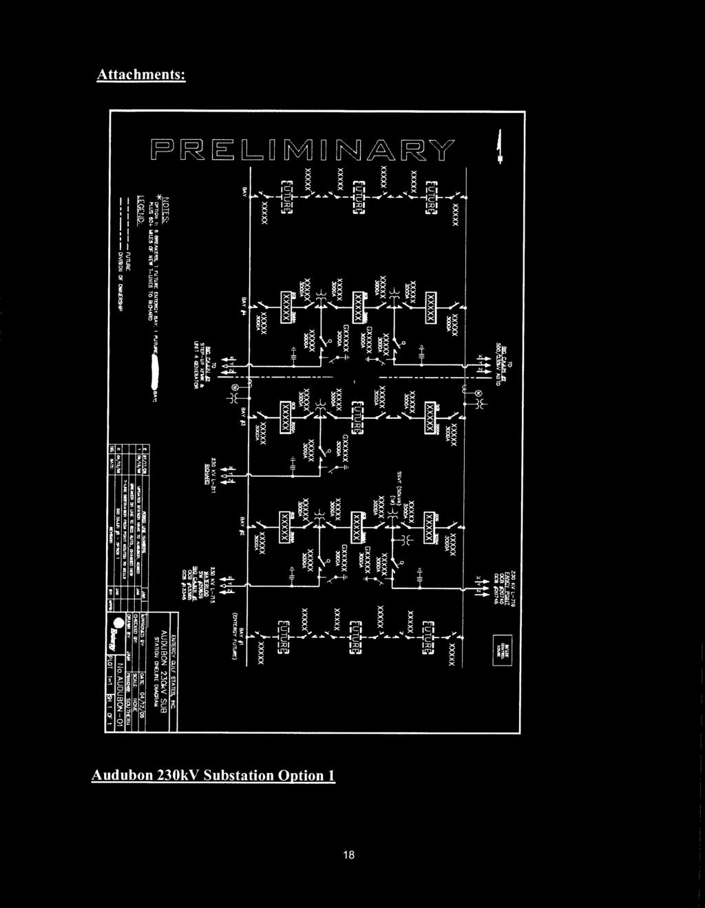
4 3. SCOPE DETAILS: Transmission Substation - During the substation scope requirement discussion it was decided by the JET to scope and estimate the following (2) alternatives as the best solutions to recommend to the customer. Option 1 New 230 kv Line from Richard to Audubon Option 1 - Substation Audubon Substation Option 1 Assumptions: 8 Breakers - 3-Bays (In-service), 2 Meters, with a New 230kV T-Line from Richard (Lafayette) to the new Audubon Substation at Big Cajun 2 Unit 4. Electrical: 1) NRG Energy will use their own control house for their portion of the yard. 2) Entergy control house will be 20'X36', fabricated. 3) Relay/metering Pts and CTs, and LAs, will be pedestal mounted at ground level. 4) Switches for future breakers in proposed bays to be included. 5) Primary station service source by Entergy, in the form of an SSVT. 6) Backup station service source to be provided by NRG Energy. 7) Assume fault current to be below 40kA. 8) Assume substation to be designed for 3000A. 9) Assume motor-operated switches with ground blade attachments on all exits. 10) Assume LA s on all exits. 11) Lightning protection study to be performed. Foundation: 1) Foundations associated with future Entergy breakers in proposed bays to be included. 2) Assume (3) PT and (3) LA foundations under all towers (some future). 4
5 3) Grounding study to be performed. 4) Assume conduits to foundations which are installed for future. 5) Foundations for future NRG Energy bay, with the exception of the bus, are not included. 6) Assume pour-in-place cable trough. Site: 1) Site to be approximately 450' wide x 450' long to accommodate 5 bays across (48' spacing), roadways, etc. 2) "Assume site size for: (2) Entergy bays (1) Entergy future bay (1) NRG Energy bay (1) NRG Energy future bay" 3) Assume no piles necessary (there are no pilings at nearby Fancy Point). 4) Assume site is clear (i.e. no trees, etc.) 5) Site quantities are double that of the Iberville project, as the proposed site would be double the size. The site estimate to be revised by site designer for definition estimate. Audubon Substation & Fancy Point Substation Relay requirements: Existing Line from Fancy Point to Big Cajun #1 has microwave communication with Type 40 tone equipment. Purchase/install Two (2) Entergy standard line/bkr panels with tone equipment. Line/bkr panel at Fancy Point has electromechanical relays. Assuming the same at Big Cajun #1, relay panels will need to be upgraded to match the panels at Audubon. Assume Entergy Substations only to purchase panel for Fancy Point Sub. Assuming fiber communication on both Big Cajun #2 lines, purchase/install two (2) Entergy standard line/bkr panels with fiber communication. Three (3) breaker control panels Two (2) bus differential panels One (1) six switch MOS panel Fifteen (15) 230kv CVT s with relaying accuracy Six (6) 230kv CVT s with metering accuracy Six (6) 230kV CT s with metering accuracy 5
6 One (1) two meter revenue metering panel Seven (7) each indoor and outdoor CVT junction boxes Two (2) metering CT junction boxes One (1) RTU large One (1) Stand alone AC panel One (1) Stand alone DC panel One (1) set of batteries with rack 270AH One (1) battery charger 50A One (1) battery switching panel 200A One (1) customer demarc box Misc. communications equipment Misc. fiber equipment Control cable Option 1 Metering (2) Meters installed on bus (interconnection to NRG). Install (1) metering panel for NRG tie metering to totalize the (2) NRG interconnections. Additional retail auxiliary load metering may be necessary for NRG interconnections by the applicable retail service provider (NRG & Entergy) depending on load flow projections. Audubon Substation - Wholesale metering on the East and West busses at the interconnections to NRG. Metering on additional interconnections will depend on actual substation electrical arrangement whether Option 1 or Option 2. Audubon Transmission Line Cut in Locations 1) A North direction has been assumed on the one-line based on locations of related stations. Final orientation to be determined with Site and T-Lines input for best case considering line routing and expandability. 2) Assume line segment between BC1 and BC3 will keep L-715 nomenclature; segment between BC3 and Fancy Point (shorter segment) will need new name, L 719 has been proposed. 6
7 Option 1 - Richard 500/230kV Substation Electrical: 1) Control house has enough room for new panels, etc. 2) Assume existing station service is adequate. 3) Relay/metering Pts and CTs, and LAs, will be pedestal mounted at ground level. 4) Assume 63kA breakers (oneline shows fault current above 40kA). 5) Assume (4) single phase 400MVA 500/230kV autos. 6) Assume, based on auto rating, that 230kV equipment will be 3000A and 500kV equipment will be 2000A. 7) Lightning protection study to be performed. 8) "Assume equipment to be installed: (5) 500kV switch (2) 500kV breakers (4) Single phase 500/230kV autos w/firewalls (2) 230kV switches (1) 230kV breaker (1) 230kV dead end Foundation: 1) Assume adequate space in control house entrances for new conduit runs. 2) Grounding study to be performed. Site: 1) Site to be expanded to the North (near Northwest corner) app. 200'x350'. 2) Assume no piles necessary (there are no pilings at Richard). 3) Site estimate to be revised by site designer for defintion estimate. 4) Assume no oil containment. 7
8 Option 1 - Richard 500kV Substation Relay requirements: One (1) Line/breaker panel with primary and backup line relays for 230kV breaker and Audubon 230kV line. Primary differential relaying between low side of 230kV breaker and 500kV side of the autotransformer. Primary differential relaying between 230kV side and 500kV side of the autotransformer. Primary differential relaying between 230kv side of the autotransformer and both new 500kV breakers. Backup differential relaying between 500kV side of the autotransformer and both new 500kV breakers. Primary and backup differential relaying between one new 500kV breaker and 500kV breaker Two (2) breaker control panels for new 500kV breakers. Two (2) 500kV CVT s with relaying accuracy One (1) 230kV CVT with relaying accuracy Three (3) single phase CVT junction boxes Three (3) 230kV CVT s with relaying accuracy One (1) each indoor & outdoor CVT junction boxes One (1) CT junction box One (1) one meter revenue metering panel One (1) five switch MOS panel. Assumptions: RTU is adequate Control house size is adequate Batteries are adequate AC & DC panels are adequate Transmission Lines: Cut-in Richard Final line entrance orientation to be determined with Site and T-Lines input for best case considering line routing and expandability. Option 1 - Transmission Lines: The Transmission line portion of this project was estimated in (2) components. 1) The T-Line interconnection at the new 230kV Substation. 2) Transmission System Line Upgrades: Build a new 230kV Line from Audubon to Richard. 8
9 T-Line Interconnection requires 2 miles of 230kV T-Line, an in and out Loop following along the existing 500kV - Line 745 ROW This option recommends a single circuit in and out, on parallel structures in the existing, or a new parallel adjacent right-of-way. This option was selected as the best alternative based on ROW acquisition cost and duration with the impact being less severe to bordering land owners. Audubon - Big Cajun 230kv - L 715 (In) All dead-ends (4) are steel base plated with base plated vibe piles foundations. All tangents (7) are concrete with 15 ft direct embedment. Audubon - Fancy Point 230kV - L 719 (Out) All dead-ends (4) are steel base plated with base plated vibe piles foundations. All tangents (7) are concrete with 15 ft direct embedment. New ~76 Mile Line: This option was determined to be the optimum choice in adding a new 230kV Line in the same ROW as the existing 138kV lines being proposed for upgrades, and along an existing 500kV corridor, thus reducing the ROW cost and duration while also being accomplished without affecting every substation along the proposed line route. The outage durations would be much shorter, and would not cause the system issues that the rebuild would. The proposed new 230kV line will be designed and constructed in 6 sections to allow for parallel activities of ROW acquisition, clearing, surveying/staking, and construction simultaneously to occur thus reducing the duration for the construction of the new line. Audubon Richard - New 230kV - L 311 (Richard to the Wells turn off) miles All dead-ends (9) are steel base plated with base plated vibe piles foundations. All tangents (125) are concrete with 15 ft direct embedment. Audubon - Richard 230kV - L 311 (Wells turn off to East Floodway Levee) miles All dead-ends (19) are steel base plated with base plated vibe piles foundations. All tangents (233) are concrete with 15 ft direct embedment. Audubon - Richard 230kV L -311 (East Levee to Atchafalaya River) miles (Swamp) All dead-ends (4) are steel base plated with base plated vibe piles foundations. All tangents (45) are concrete with 15 ft direct embedment. The Gypsy-Waterford river crossing estimate was used for the 3M conductor. 9
10 Audubon - Richard 230kV L -311 (Atchafalaya River to West Levee) miles (Swamp - Double circuit) This section will be built double circuit with 138kV line L-641. All dead-ends (10) are steel base plated with base plated vibe piles foundations. All tangents (53) are steel base plated with base plated vibe piles foundations. Audubon - Richard 230kV L -311 (West Levee to 500kV Junction) miles (Double circuit) This section will be built double circuit with 138kV line L-641/287/289. All dead-ends (20) are steel base plated with base plated vibe piles foundations. All tangents (135) are concrete with 15 ft direct embedment. Option 2 Rebuild 138 kv Lines and Substations to 230 kv Option 2 - Substation Audubon Substation Option 2 Assumptions: 5 Breakers - 2 Bays (In-Service) - 2 Meters along with System T - Line upgrades which do not directly tie-into the new substation. Electrical: 1) NRG Energy will use their own control house for their portion of the yard. 2) Entergy control house will be 20'X36', fabricated. 3) Relay/metering Pts and CTs, and LAs, will be pedestal mounted at ground level. 4) Switches for future breakers in proposed bays to be included. 5) Primary station service source by Entergy, in the form of an SSVT. 6) Backup station service source to be provided by NRG Energy. 7) Assume fault current to be below 40kA. 8) Assume substation to be designed for 3000A. 9) Assume motor-operated switches with ground blade attachments on all exits. 10) Assume LAs on all exits. 11) Lightning protection study to be performed. 10
11 Foundation: 1) Foundations associated with future Entergy breakers in proposed bays, as well as all future Bay 3 foundations, to be included. 2) Assume (3) PT and (3) LA foundations under all towers (some future). 3) Grounding study to be performed. 4) Assume conduits to foundations which are installed for future. 5) Assume pour-in-place cable trough. 6) Foundations for future NRG Energy bay, with the exception of the bus, are not included Site: 1) Site to be approximately 450' wide x 450' long to accommodate 5 bays across (48' spacing), roadways, etc. 2) "Assume site size for: (1) Entergy bay (2) Entergy future bays (1) NRG Energy bay (1) NRG Energy future bay" 3) Assume no piles necessary (there are no pilings at nearby Fancy Point). 4) Assume site is clear (i.e. no trees, etc.) 5) Site quantities are double that of the Iberville project, as the proposed site would be double the size. The site estimate to be revised by site designer for definition estimate. Transmission Line Cut in Locations 1) A North direction has been assumed on the one-line based on locations of related stations. Final orientation to be determined with Site and T-Lines input for best case considering line routing and expandability. 2) Assume line segment between BC1 and BC3 will keep L-715 nomenclature; segment between BC3 and Fancy Point (shorter segment) will need new name. L 719 has been proposed. 11
12 Option 2 -Audubon Relay Existing Line from Fancy Point to Big Cajun #1 has microwave communication with Type 40 tone equipment. Purchase/install Two (2) Entergy standard line/bkr panels with tone equipment. Line/bkr panel at Fancy Point has electromechanical relays. Assuming the same at Big Cajun #1, relay panels will need to be upgraded to match the panels at Big Cajun #3. Assume Entergy Substations only to purchase panel for Fancy Point Sub. Assuming fiber communication on both Big Cajun #2 lines, purchase/install two (2) Entergy standard line/bkr panels with fiber communication. One (1) breaker control panel One (1) bus differential panel One (1) six switch MOS panel Nine (9) 230kv CVT s with relaying accuracy Six (6) 230kv CVT s with metering accuracy Six (6) 230kV CT s with metering accuracy One (1) two meter revenue metering panel Five (5) each indoor and outdoor CVT junction boxes Two (2) metering CT junction boxes One (1) RTU large One (1) Stand alone AC panel One (1) Stand alone DC panel One (1) set of batteries with rack 270AH One (1) battery charger 50A One (1) battery switching panel 200A One (1) customer demarc box Misc. communications equipment Misc. fiber equipment Control cable Metering Option 2 (2) Meters installed on bus (interconnection to NRG). Install (1) metering panel for NRG tie metering to totalize the (2) NRG interconnections. Additional retail auxiliary load metering may be necessary for NRG interconnections by the applicable retail service provider (NRG & Entergy) depending on load flow projections. 12
13 Audubon Substation - Wholesale metering on the East and West busses at the interconnections to NRG. Metering on additional interconnections will depend on actual substation electrical arrangement whether Option 1 or Option 2. Relay Settings Scope and estimate assumptions were based on the scope requirements for protective relaying for both Option1 and Option 2. A detailed scope and estimate will be prepared during the project s Definition Phase. RTU Configuration Scope and estimate assumptions were based on the scope requirements for protective relaying for both Option1 and Option 2. A detailed scope and estimate will be prepared during the project s Definition Phase. SCADA Scope and estimate assumptions were based on the scope requirements for protective relaying for both Option1 and Option 2. A detailed scope and estimate will be prepared during the project s Definition Phase. Option 2 - Transmission Lines: The Transmission line portion of this project was estimated in (2) components. 1) The T-Line interconnection at the new 230kV Substation. 2) Transmission System Line Upgrades: Option 2 - Rebuild and upgrade of an existing 138kV line from Wilbert to Champagne, then build a new section to Richard T-Line Interconnection - Option 2 requires 2 miles of 230kV T-Line, an in and out Loop following along the existing 500kV - Line 745 ROW This option recommends a single circuit in and out, on parallel structures in the existing, or a new parallel adjacent right-of-way. This option was selected as the best alternative based on ROW acquisition cost and duration with the impact being less severe to bordering land owners. Audubon - Big Cajun 230kv - L 715 (In) All dead-ends (4) are steel base plated with base plated vibe piles foundations. All tangents (7) are concrete with 15 ft direct embedment. 13
14 Audubon - Fancy Point 230kV - L 719 (Out) All dead-ends (4) are steel base plated with base plated vibe piles foundations. All tangents (7) are concrete with 15 ft direct embedment. Transmission System Line Upgrades: Note: It should be noted emphasis was placed on using existing T-Line ROW when considering the Rebuild and New Line as permissible. 138kV Line Rebuild: When considering the re-building of the existing 138kV T-Lines to 230kV standards recommended in Transmission Planning s study, consider the following options. This would require upgrading the 138kV Lines and all of the 138kV Substations along the proposed route being converted to 230kV. This option was determined to be cost prohibitive and could run 50 % to 60 % higher than constructing a new 230kV line. A high level estimated cost of $200M+ was projected. It was decided by the project facility team to focus on the most viable alternatives to deliver the best scope and cost assumptions to the customer. General Section Option 1 and Option 2 Construction Management Plan - A detailed construction plan will be developed during the project definition phase which will be incorporated in the Project Execution Plan to provide specific management activities which will be implemented during the project execution phase. Asset Management The Asset management organization s role will be to provide support in ROW clearing, Transmission Operational activities. These roles will be developed during the project definition phase, incorporated in the Project Execution Plan, and implemented during the execution phase. 14
15 RIGHT-OF-WAY Option 1 and Option 2 Interconnection Substation and T-line Cut-in: Identify near-by landowners (major), Industrial Plants, other customer contact information will be provided by NRG for substation interconnection ROW. New T- Line ROW/ Environmental Requirements : The assumptions listed below will be required to secure the T-Line ROW adjacent to existing Line ROW currently in place. Acquire right of way (property only): 18.5 miles from Audubon to Line 315, 19.5 miles from Line 289 to Richard Abstract of property: 18.5 miles from Audubon to Line 315, 19.5 miles from Line 289 to Richard Abstract of property within existing R/W: (This is for permitting requirements) Appraisals of property: 18.5 miles from Audubon to Line 315, 19.5 miles from Line 289 to Richard Recordation of documents in courthouse Surveying/Staking The entire proposed T-Line length. Environmental Permitting (including mitigation) (Highway, Railroad, Army Corp, State, Scenic Rivers, Etc. Permits) ROW Damages (Sugarcane, Soybean, Wheat, Crayfish, Rice, Property, Etc.) Outages A detailed outage plan and schedule will be developed during the project definition phase which will be incorporated in the Project Execution Plan to provide specific outage management activities which will be submitted to the TOC/SOC in AORS well in advance for review and approval. High Level Outages that have been identified in the study are as follows: 15
16 T-Line interconnections Audubon and Richard T-Line construction - Audubon - Richard 230kV L -311 (Atchafalaya River to West Levee) miles (Swamp - Double circuit) Audubon - Richard 230kV L -311 (West Levee to 500kV Junction) miles (Double circuit) High Level Risk Identification Risk ID/ Probability/Estimated Cost/Response A detailed Risk Management Plan and mitigation schedule will be developed during the project definition phase, using Front End Loading, and Risk Weighting Analysis. The Risk Management Plan will be incorporated into the Project Execution Plan to provide specific management processes which will be implemented throughout the project s lifecycle. 4. COST: Option 1 Component Direct Cost Indirect Full Financial Audubon 230kV Substation $9, 633, 309 $4, 986, 090 $14, 619, 399 Richard 500kV Substation $17, 238, 058 $8, 727, 834 $25, 965, 892 Substation Total $26, 871, 376 $13, 713, 924 $40, 585, 291 Transmission Line Interconnection Cut-In $1, 746, 732 $868, 377 $2, 615, 109 New 230kV Line (76mi) $65, 951, 148 $32, 360, 271 $98, 311, 419 Transmission Line Total $67, 697, 880 $33, 228, 648 $100, 926, 528 Note: Total Project Cost $94, 569, 247 $46, 942, 572 $141, 511, 819 It should be noted there was a direct cost decrease compared to the initial draft Facilities Study due to 3.3 miles of the new 230kV Line being removed from the proposed new line, as the interconnection at Wells 500kV substation is not being required for the project s scope recommendations. However the indirect cost, (overheads) have increased since the original draft Facilities Study was issued in July
17 The current estimate reflects the latest increases to the indirect (overhead) costs. Thus the overall projected cost of the project has increased due to this occurrence. The ICT has reviewed the projects identified and have determined that all projects should be classified as Supplemental Upgrades. For more information on cost responsibility for Base Plan and Supplemental Upgrades, see Attachment T to Entergy s OATT. Option 2 Option 2 was reviewed and an order of magnitude estimate was prepared. This option was determined to be cost prohibitive and could run 50 % to 60 % higher than constructing a new 230kV line. A high level estimated cost of $200M+ was projected. It was decided by the project facility team to focus on the most viable alternatives to deliver the best scope and cost assumptions to the customer. 5. SCHEDULE: ROW BEING CRITICAL PATH Option 1 Component Start Finish Duration Rev. 1 Facility Study 4/6/07 5/11/07 30 Days Review Project Definition/Detailed 5/21/2007 7/2/ Days Estimate/ PEP Rev. 0 Project Funding Approval 7/2/07 7/13/07 30 Days Internal/External Transmission Line New 230kVT-line ROW 7/13/07 7/13/10 36 Months Detailed Design 7/20/07 7/20/09 24 Months Construction 1/30/2008 7/30/ Months Substations ( with T- Line Cut-in at both) Audubon ROW 7/13/07 7/13/09 24 Months Detailed Design 7/20/07 7/20/ Months Construction 9/30/2008 3/30/ Months Richard ROW 7/13/07 7/13/09 24 Months Detailed Design 7/20/07 7/20/ Months Construction 9/30/2008 3/30/ Months 17
18
19 Attachments: Richard 500kV Substation Opt. 1 19
20 Appendix 1 Questions from NRG on the Interconnection Draft Facilities Study with Entergy Responses Entergy s responses to NRG s questions from the scoping and review meeting of the draft Facilities Study. 1) What is the process for the Letter of Intent to proceed with certain upgrade activities and also how it would affect the LGIP schedule? The use of a Letter of Intent to proceed with certain upgrades would be governed by the following (and any other related) requirements of the LGIP and LGIA. Construction of facilities to be transferred to Entergy will require execution of an EPC agreement between Entergy and NRG. Please note that Entergy does not allow an Interconnection Customer to perform construction work in or on any in-service Entergy transmission facilities. Per Section 9 of the LGIP: Engineering & Procurement ('E&P') Agreement. Prior to executing an LGIA, an Interconnection Customer may, in order to advance the implementation of its interconnection, request and Transmission Provider shall offer the Interconnection Customer, an E&P Agreement that authorizes Transmission Provider to begin engineering and procurement of long lead-time items necessary for the establishment of the interconnection. The E&P Agreement is an optional procedure and it will not alter the Interconnection Customer's Queue Position or In-Service Date. Per Section 5 of the LGIA: 5.1 Options. Unless otherwise mutually agreed to between the Parties, Interconnection Customer shall select the In-Service Date, Initial Synchronization Date, and Commercial Operation Date; and either Standard Option or Alternate Option set forth below for completion of Transmission Provider's Interconnection Facilities and Network Upgrades as set forth in Appendix A, Interconnection Facilities and Network Upgrades, and such dates and selected option shall be set forth in Appendix B, Milestones Option to Build. If the dates designated by Interconnection Customer are not acceptable to Transmission Provider, Transmission Provider shall so notify Interconnection Customer within thirty (30) Calendar Days, and unless the Parties agree otherwise, Interconnection Customer shall have the option to assume responsibility for the design, procurement and construction of Transmission Provider's Interconnection Facilities and Stand Alone Network Upgrades on the dates specified in Article Transmission Provider and Interconnection Customer must agree as to what constitutes Stand Alone Network Upgrades and identify such Stand Alone Network Upgrades in Appendix A. Except for Stand Alone Network Upgrades, Interconnection Customer shall have no right to construct Network Upgrades under this option. 20
21 2) What is Entergy s position on the upgrades that NRG could perform, the process for Entergy s CFO approval, and the anticipated impacts to the LGIP schedule if NRG performed a portion of the upgrades? Entergy will follow the requirements of the LGIP and LGIA with regard to upgrades that NRG could perform. Entergy considers a Stand Alone Network Upgrade to be a Greenfield facility that does not require construction work either in or on Entergy owned facilities. Should NRG wish to pursue this option, Entergy would present NRG with an EPC Agreement to execute that details Entergy s requirements with regard to design, construction, acceptance, and transfer of transmission facilities to Entergy. It was a misunderstanding that approval by the Entergy CFO was required to assure that normal Entergy overheads are not applied to the cost of facilities transferred to Entergy. It has been clarified that such approval is not required. The timing of the transfer is coordinated with Entergy s accounting personnel to assure that such overheads are not applied to applicable costs. Schedule impacts due to NRG s option to perform a portion of the upgrades are in accordance with the applicable portions of the LGIP and LGIA. 3) a. NRG requests that Entergy reevaluate CLECO s impacts on the Entergy transmission system and determine CLECO s upgrade cost responsibility. A reevaluation of the Rodemacher Affected System Study was conducted to determine the impact of the new Rodemacher generating station located at the existing Rodemacher site in CLECO s control area. The idev s for adding the new Rodemacher generator was obtained from CLECO along with their expected dispatch. The study shows that the new 600MW Rodemacher generator has a 5MW impact on the Wilbert Livonia Krotz Springs Champagne 138kV transmission lines for the loss of the Webre Wells transmission 500kV line. This is less than the 3% OTDF required. CLECO generation addition at Rodemacher has no significant impact on the identified upgrades for the NRG new generation addition or any other facilities on the Entergy System. b. Then NRG requests that Entergy model the impacts of BC2, Unit 4 and determine NRG s upgrade cost responsibility. There are no impacts to this Facility Study caused by CLECO s generation addition at Rodemacher. The ICT has the responsibility of determining the cost allocation of the identified upgrades. 4) What is Entergy s position on how the LGIP schedule is impacted by the time needed to perform the above mentioned model reevaluations? The LGIP is continuing on an active basis and is not significantly impacted by the above mentioned reevaluations. 5) How will the assignment of upgrades be determined by these model changes? No changes resulted in the assignment of upgrades from these model changes. 21
22 6) What impact might the filing of a non-standard I/A have on the LGIP schedule? Based on the uncertainty associated with how Entergy will comply with Texas Senate Bill 7 to provide a Qualified Power Region for Entergy customers in Texas, NRG asked what options are available to it regarding its NRIS request. For example, depending on the timing and impact to NRG s NRIS status in Texas (i.e. ability to be deliverable to Entergy network load in Texas), would NRG have the ability to amend its LGIA? In order to change its proposed interconnection, would NRG be required to cancel its current request and submit an entirely new interconnection request? The options for Entergy to comply with Texas Senate Bill 7 will be addressed in filings with the Public Utility Commission of Texas (PUCT) and the FERC. NRG has the ability to intervene in these proceedings to have its issues/concerns addressed. If NRG executes an LGIA for NRIS prior to any decision on Entergy s compliance with Texas Senate Bill 7, NRG s rights under the LGIA should be preserved going forward. If NRG believes its rights under the LGIA are not preserved, it can raise this concern with the appropriate party. 7) How will the I/A and TSA processes work in tandem? NRG is in negotiations with at least three network customers to supply their loads from BC2 U4. There are three NITS requests in study mode that have been submitted via OASIS with BC2 U4 designated as the source. NRG is concerned that if it executes an LGIA for NRIS and funds the identified upgrades (approximately $120 million); other parties may be able to reserve transmission service utilizing the upgraded capacity before their prospective customers can confirm the requested service. NRG has asked whether (1) NITS customers and NRG should execute agreements at the same time; or (2) if NRG should elect ERIS only and the NITS customers should be responsible for upgrades to have their requested service granted. NRG indicated it could enter into a side arrangement with the NITS customers to fund the upgrades. NRG must make its decision on how to proceed. Entergy will explain the process, but will not recommend a course of action. Based on the three prospective customers having positions in the transmission service queue, other customers requesting service that may utilize the network upgrades funded by NRG to receive NRIS status would have positions lower in the queue. Therefore, the three parties already in the queue would have priority rights to available service. 8) LaGen System Dispatch The generation dispatch changes made to the CLECO and LaGen control areas have resulted in significant deviations from the impacts originally identified in the SIS. We are unclear as to why this was done and the impact of this assumption, and thus request that Entergy analyze the impact of correcting this dispatch assumption. Entergy s basis for performing the Network Resource Integration Service (NRIS) is to preserve the injection rights for existing generation units. To accomplish this, all of the existing network generators in the local area will be turned on to their designated network injection rights and firm point to point transactions. For NRG Big Cajun 1 units 1, 2, 3, and 4 were turned on for 450MW, Big Cajun 2 units 1, 2 and 3 were turned on for 1728MW. The output of Bayou Cove generation was reduced by 247MW for a total of 62MW, and the transaction to Entergy was reduced to 62MW from 320MW. The reduction of Bayou Cove was simulated to produce different generator sensitivities thereby maintaining the output levels of Big Cajun to their firm point to point and NITSA contract levels. 22
23 Bus Number/Name Id In- Service Pgen (MW) Pmax (MW) [1BC2 U ] [1BC2 U ] [1BC2 U ] [1BC1 U ] [1BC1 U ] [1BC1 U ] [1BC1 U ] [1BC2 UC ] These levels are consistent with the NITSA s for LaGen and EMO and Point to Point for SMEPA. 9) NRG asks that Entergy consider the addition of a series reactor on the proposed 230 kv Big Cajun Unit 4 Wells transmission line. Analysis of the 230 kv reactor proposed by NRG does not provide a sufficient long term solution for the Entergy system. Based on the study results, with the BC2 Wells 230kV line, including the reactor, overloads were observed in the Lafayette area, and the new BC2 generation was not fully dispatched. (Bonin 230/138kV transformer loading is 341MVA, rating is 300MVA.) Additional analysis was conducted using the latest base case models and it was determined that the best solution is to bypass Wells 230kV substation and go directly to Richard with the line from Big Cajun 2 230kV. 10) NRG asks that Entergy consider following options: a) Mt. Olive Hartburg Series Compensation, and b) Bogalusa Chitto. Entergy has investigated the proposed upgrades of adding 50% series compensation on the Hartburg Mount Olive 500kV line, adding Boga Chitto 500kV substation on the Daniel McKnight 500kV line and building a 500kV line from Boga Chitto to Bogalusa 500kV substation. The upgrades do provide a benefit the first years of service; however, these upgrades are not long term solutions that will maintain the deliverability of this generator. The Entergy planning cost estimates for Boga Chitto and the series compensation are approximately $100M. This proposed option will require an Affected System Study for Southern Company and SMEPA. These Affected System Studies could add additional costs for projects in Southern Company and SMEPA. Results from these studies indicate a more expensive option that does not solve the local issues on the 230 kv system and does not provide the benefits equal to the 230kV option presented to NRG. 11) NRG asks that Entergy consider the following options: a) Mt. Olive Hartburg Series Compensation, and b) McKnight Daniel Phase Shifting Transformer Adjustment. Entergy has investigated the proposed upgrades of changing the phase shifter angle on the Daniel 500kV/230kV transformer to 16 degrees from 27 degrees and adding 50% series compensation on the Hartburg Mount Olive 500kV line. The flow on the underlying transmission system is reduced for the loss of the Webre Wells 500kV line with the Big Cajun 2 Unit 4 on generating 710MW. However, these upgrades will not be long term solutions that can maintain the deliverability of this generator. Also, changing the phase shifter angle will require an Affected System Study with Southern Company, SMEPA and TVA. These adjoining utilities have built their transmission system with the phase shifter in at existing angle, and any changes in this angle will increase flows on their transmission system that has not been planned for. The total cost for changing the angle on the phase shifter will have to be calculated by the 23
24 affected systems. These Affected System Studies could add additional costs for projects in Southern Company and SMEPA. Results from these studies indicate a more expensive option that does not solve the local issues on the 230 kv system and does not provide the benefits equal to the 230kV option presented to NRG. 12) Base Case Overloads NRG requests that Entergy cooperate with the Southwest Power Pool, as the Independent Coordinator of Transmission (ICT), to expedite its establishment of its base case models so that the impacts of any base plan upgrades, as well as the characterization of the upgrades identified in any final facilities study, can be determined. Entergy is in compliance with the NERC reliability criteria. The ICT is working now as of November 17, 2006 to establish the base plan criteria consistent with the FERC order. The proposed projects for this study have not been identified in the ICT s Interim Base Plan. The ICT is responsible for determining cost allocations to these proposed projects. 13) Entergy Business Practice Regarding Overloads Entergy is in compliance with the NERC reliability criteria. The ICT is working now as of November 17, 2006 to establish the base plan criteria consistent with the FERC order. The proposed projects for this study have not been identified in the ICT s Interim Base Plan. The ICT is responsible for determining cost allocations to these proposed projects. 14) Base Case Model Changes The changes to base case were necessary to reflect most recent load projections and prevailing firm transmission services (expiration of Acadia contract with CLECO). 15) Discrimination in the Assignment of Upgrade Costs It is not clear that Entergy is assigning the cost responsibility of upgrades consistently with principle of cost-causation. Entergy is in compliance with the NERC reliability criteria. The ICT is working now as of November 17, 2006 to establish the base plan criteria consistent with the FERC order. The proposed projects for this study have not been identified in the ICT s Interim Base Plan. The ICT is responsible for determining cost allocations to these proposed projects. 16) Least Cost Options NRG requests that Entergy explain their process for evaluating all options, determining least cost solutions, and how the system upgrades assigned to NRG in the Facilities Study were the result of a least cost planning process. Entergy utilized the same process for reviewing alternatives that it would use on projects being funded by Entergy. The alternatives were based on Entergy s knowledge of existing facilities, the Facilities Study results, Entergy s best engineering judgments, various time factors, etc. 24
25 17) System Impact Study NRG is requesting that Entergy provide an updated SIS and all work papers, spreadsheets, load flow analysis summaries, and dispatches related to the impacts of base case model changes. Entergy has worked very closely with NRG and their consultants to accurately communicate and transmit all model revisions for this interconnection study and Entergy has followed the LGIP. The additional analysis required for the additional scenarios and additional affected system study does not change the results; therefore, no revisions are required to the affected system study. 18) Entergy Texas Integration Plan Entergy should provide an explanation of how the installation of DC terminals to integrate its Texas load under ERCOT will affect the NRIS status of Big Cajun Unit 4, and whether upgrades can be deemed conditional based upon the final resolution of this issue. If NRG executes an LGIA for NRIS prior to any decision on Entergy s compliance with Texas Senate Bill 7, NRG s rights under the LGIA should be preserved going forward. In accordance with FERC Order 2003, Entergy will file the LGIA as included in Attachment O to Entergy s OATT. The appropriate appendices will be incorporated into that LGIA. Should NRG disagree with the manner in which upgrades are defined in the LGIA, you may request that the agreement be filed un-executed and that your concerns be expressed as part of that filing. Entergy may then agree to proceed with design and construction activities pending FERC action. 19) NRG would like Entergy to explain how NRG s rights under NRIS will be preserved if network loads in Texas, become isolated on the other side of the ERCOT/Eastern Interconnect interface as proposed in the recent Entergy 2006 Transmission Planning Summit. If NRG executes an LGIA for NRIS prior to any decision on Entergy s compliance with Texas Senate Bill 7, NRG s rights under the LGIA should be preserved going forward. Because it is not finalized how or even if the Texas Integration plan will proceed, it is impossible to answer at this time how that will be addressed in the integration. If NRG believes its rights under the LGIA are not preserved, it can raise this concern with the appropriate Regulatory party. 25
26 26
Feasibility Study on Load Flow and Short Circuit Project
 Feasibility Study on Load Flow and Short Circuit Project 101813-01 Prepared by: Transmission Planning Department Cleco Corporation, Inc. 2180 St. Landry Hwy P.O. Box 70 St. Landry, LA 71367 Final November
INTERCONNECTION FACILITIES STUDY REPORT
 Interconnection Request No. TI-08-0312 INTERCONNECTION FACILITIES STUDY REPORT Prepared by Tri-State Generation and Transmission Association, Inc. 1 of 7 DISCLAIMER OF WARRANTIES AND LIMITATION OF LIABILITIES
TSR A & B - FACILITIES STUDY REPORT
 TSR-11-0502A & B - FACILITIES STUDY REPORT Transmission Service Request No. TSR-11-0502A&B 2 x 25 MW Wind Energy Generating Facilities From POI on Gladstone Walsenburg 230 kv Line to Ojo Substation 345
Small Generator Interconnection Facilities Study Report. Completed for. ( Interconnection Customer ) Proposed Interconnection Pavant substation
 Proposed Interconnection Pavant substation") Small Generator Interconnection Facilities Study Report Completed for ( Interconnection Customer ) Proposed Interconnection Pavant substation Original report dated February 17, 2016 Revised March 11, 2016
Small Generator Interconnection Facilities Study Report Completed for ( Interconnection Customer ) Proposed Interconnection Pavant substation Original report dated February 17, 2016 Revised March 11, 2016
Small Generator Interconnection Facilities Study Report. Completed for Q0314 ( Interconnection Customer ) A Qualified Facility
 A Qualified Facility") Small Generator Interconnection Completed for Q0314 ( Interconnection Customer ) A Qualified Facility Proposed Interconnection PacifiCorp s 34.5-kV West Cedar Substation December 29, 2010 TABLE OF CONTENTS
Small Generator Interconnection Completed for Q0314 ( Interconnection Customer ) A Qualified Facility Proposed Interconnection PacifiCorp s 34.5-kV West Cedar Substation December 29, 2010 TABLE OF CONTENTS
Generation, Transmission, and End User Facilities
 Procedures for Interconnection of Generation, Transmission, and End User To the Grand River Dam Authority Transmission System Table of Contents GRDA/SPP Interaction... 3 Standards... 3 Generation... 3
SOUTH TEXAS ELECTRIC COOPERATIVE, INC.
 SOUTH TEXAS ELECTRIC COOPERATIVE, INC. P.O. Box 119 Nursery, Texas 77976 (361) 575-6491 Fax (361) 576-1433 Transmission Interconnection Requirements Table of Contents I. Introduction II. Interconnection
Q44 Generation Interconnection
 A subsidiary of Pinnacle West Capital Corporation Q44 Generation Interconnection Interconnection Facilities Study APS Contract No. 52129 By Arizona Public Service Company Transmission Planning August 19,
Generation Interconnection Feasibility Study Report
 Project 76 Generation Interconnection Feasibility Study Report December 21, 2007 Electric Transmission Planning Table of Contents Table of Contents... 2 Executive Summary... 3 Network Resource Interconnection
Generator Interconnection Process. Wholesale Transmission Overview
 1 Generator Interconnection Process Wholesale Transmission Overview 2 This presentation summarizes the FERC-approved Generator Interconnection Procedures (GIP) in Appendix Y of the California Independent
Memorandum. This memorandum requires Board action. EXECUTIVE SUMMARY
 California Independent System Operator Corporation Memorandum To: ISO Board of Governors From: Keith Casey, Vice President, Market & Infrastructure Development Date: May 21, 2014 Re: Decision on interconnection
Small Generator Interconnection Tier 4 Facilities Study Report. Completed for. ( Interconnection Customer ) A Qualifying Facility Q0662
 A Qualifying Facility Q0662") Small Generator Interconnection Tier 4 Facilities Study Report Completed for ( Interconnection Customer ) A Qualifying Facility Q0662 Proposed Interconnection Klamath Falls-Fishhole 69 kv line at approximately
Small Generator Interconnection Tier 4 Facilities Study Report Completed for ( Interconnection Customer ) A Qualifying Facility Q0662 Proposed Interconnection Klamath Falls-Fishhole 69 kv line at approximately
Requests for Clarifications And Responses Order No. 754 Data Request The Study of Single Point of Failure
 Requests for Clarifications And Responses Order No. 754 Data Request The Study of Single Point of Failure Revised: July 12, 2013 Introduction The following information includes requests for clarification
Standard Development Timeline
 Standard Development Timeline This section is maintained by the drafting team during the development of the standard and will be removed when the standard becomes effective. Description of Current Draft
Large Generator Interconnection Generator, Transmission, & Distribution Asset Responsibilities
 Large Generator Interconnection Generator, Transmission, & Distribution Asset Responsibilities Effective Date: May 12, 2014 Revision History Date May 1, 2013 May 12, 2014 Description Initial document Revision
APPENDIX 4 to LGIP INTERCONNECTION FACILITIES STUDY AGREEMENT
 APPENDIX 4 to LGIP INTERCONNECTION FACILITIES STUDY AGREEMENT THIS AGREEMENT is made and entered into this day of, 20 by and between [Customer Name (Project Name, QXXXX)], a [Type of company] organized
Reliability Standard Audit Worksheet 1
 Reliability Standard Audit Worksheet 1 FAC-003-4 Transmission Vegetation Management. Registered Entity Name: Applicable Function(s): Applicable only for TO and GO Compliance Monitoring Method: RSAW Version:
Generation Interconnection Feasibility Study Report
 Project #169 Generation Interconnection Feasibility Study Report 7/2/2014 Regional Electric Transmission Planning TABLE OF CONTENTS Executive Summary... 3 Generator and Interconnection Data... 5 Study
REAL-TIME MONITORING DATA SPECIFICATION
 REAL-TIME MONITORING DATA SPECIFICATION Version 1 December 9, 2016 Revision History Version Date Reviewer Revisions 1 11/1/16 Mansion Hudson Initial document 1 Contents 1. DOCUMENT REVIEW... 3 2. DEFINITIONS...
Quarter 3, 2007 (2007Q3) Generation Deliverability Assessment Study Plan
 Generation Deliverability Assessment Study Plan") Quarter 3, (Q3) Generation Deliverability Assessment Study Plan Background and Purpose of Study Phases I & II Generation and Import Deliverability Studies were completed that established the deliverability
Quarter 3, (Q3) Generation Deliverability Assessment Study Plan Background and Purpose of Study Phases I & II Generation and Import Deliverability Studies were completed that established the deliverability
Supplemental Information
 Retirement of NPCC Directory# 3 Supplemental Information On April 1, 2015, NPCC Directory# 3 was retired upon the effective date of PRC-005-2 Protection System Maintenance which is subject to a 12 year
The Narragansett Electric Company. d/b/a National Grid (Rhode Island Reliability Project) RIPUC Dkt. No Testimony of. Todd G. Kopoyan, P.E.
 RIPUC Dkt. No Testimony of. Todd G. Kopoyan, P.E.") d/b/a National Grid (Rhode Island Reliability Project) RIPUC Dkt. No. 0 Testimony of Todd G. Kopoyan, P.E. February 0, 00 0 0 INTRODUCTION Q. Please state your name and business address. A. My name is
d/b/a National Grid (Rhode Island Reliability Project) RIPUC Dkt. No. 0 Testimony of Todd G. Kopoyan, P.E. February 0, 00 0 0 INTRODUCTION Q. Please state your name and business address. A. My name is
APPLICATION No. To the ALBERTA ENERGY AND UTILITIES BOARD RE:
 APPLICATION No. To the ALBERTA ENERGY AND UTILITIES BOARD RE: New 240 kv Montana Alberta Tie Ltd. (MATL) Substation 120S and Reconfigure 240kV Transmission Line 923L AltaLink Management Ltd. 2611 3 rd
Document C0. Use for:
 Date: July 27, 2015 Document C0 Use for: Connection of Electric Generation that will operate with an Open Transition (Category 1) between the Ameren System and the Generator or operate with a Synchronized
Interconnection and Transmission
 Interconnection and Transmission Gary L. Brown, P.E. Director of Energy Development Gary@ZGlobal.biz 916-985-9461 Kevin Coffee Energy Management Committee Meeting Irvine, California August 26, 2015 Interconnection
PRC Coordination of Protection Systems for Performance During Faults
 PRC-027-1 Coordination of Protection Systems for Performance During Faults A. Introduction 1. Title: Coordination of Protection Systems for Performance During Faults 2. Number: PRC-027-1 3. Purpose: To
TRANSMISSION ENGINEERING STANDARDS SUBSTATIONS
 This standard was reviewed and approved by key managers on. Officer approval of this revision is not required. 1.0 SCOPE 1.1 This guide applies to the interconnection of a generating plant with the Oncor
January 22, The Honorable Kimberly D. Bose Secretary Federal Energy Regulatory Commission 888 First Street, N.E. Washington, D.C.
 California Independent System Operator Corporation January 22, 2013 The Honorable Kimberly D. Bose Secretary Federal Energy Regulatory Commission 888 First Street, N.E. Washington, D.C. 20426 Re: California
Order No Compliance Filing Related to Interconnection Issues Proposed Transmission Interconnection Process
 Order No. 1000 Compliance Filing Related to Interconnection Issues Proposed Transmission Interconnection Process Thinh Nguyen Manager, Interconnection Projects New York Independent System Operator Joint
Revised Generation Interconnection Impact Study Report. For. Queue Position 31 ( Interconnection Customer )
") Revised Generation Interconnection Impact Study Report For Queue Position 31 ( Interconnection Customer ) September 22, 2004 1 Generation Interconnection System Impact Study Report I. Revision of Original
Revised Generation Interconnection Impact Study Report For Queue Position 31 ( Interconnection Customer ) September 22, 2004 1 Generation Interconnection System Impact Study Report I. Revision of Original
Facilities Study for the Mora Line Transmission Project. Non-Tariff Facilities Study
 Facilities Study for the Mora Line Transmission Project Non-Tariff Facilities Study November 2017 Work Performed by: Public Service Company of New Mexico Foreword This technical report is prepared for
Entergy Arkansas, Inc. Transition Plan Technical Conference #1
 Entergy Arkansas, Inc. Transition Plan Technical Conference #1 May 5, 2010 1 Why Technical Conferences? Complex subject matter Venue for stakeholders to develop an awareness and understanding of the issues
Network Configuration Document Selection for New Substations Framework
 Network Configuration Document Selection for New Substations Current version: 20/06/2018 EXTERNAL USE Page 1 of 14 Table of contents 1. Introduction... 3 1.1 Purpose... 3 1.2 Scope... 3 1.3 References...
Facility Connection Requirements. LST-FAC-001-PRO-Facility_Connection_Requirements
 Facility Connection Requirements LST-FAC-001-PRO-Facility_Connection_Requirements Document Control Document Owner: Name: Mathew Gomes Title: Director of Development & System Planning Change History: The
Standard Development Timeline
 Standard Development Timeline This section is maintained by the drafting team during the development of the standard and will be removed when the standard becomes effective. Description of Current Draft
Standard Development Timeline
 Standard Development Timeline This section is maintained by the drafting team during the development of the standard and will be removed when the standard is adopted by the NERC Board of Trustees (Board).
Memorandum. This memorandum requires Committee action.
 California Independent System Operator Corporation Memorandum To: ISO Operations Committee From: Dariush Shirmohammadi, Director of Regional Transmission - South Armando Perez, VP, Planning & Infrastructure
Standard CIP Cyber Security Critical Cyber Asset Identification
 Standard CIP 002 1 Cyber Security Critical Cyber Asset Identification Standard Development Roadmap This section is maintained by the drafting team during the development of the standard and will be removed
1. Project Description
 Page No: 1 of 16 1. Project Description 1.1 Introduction This document outlines protection, monitoring and control requirements for the shared network assets associated with establishment of Tarrone Terminal
ATC Zone 2 Projects Update U.P. Energy Summit
 ATC Zone 2 Projects Update U.P. Energy Summit Brett French Regional Manager of External Relations Michigan October 16, 2012 Helping to keep the lights on, businesses running and communities strong Project
Standard CIP Cyber Security Critical Cyber Asset Identification
 Standard CIP 002 1 Cyber Security Critical Cyber Asset Identification Standard Development Roadmap This section is maintained by the drafting team during the development of the standard and will be removed
ITC Facility Connection Requirements for Generation, Transmission and End-User Facilities Connected to the ITC Holdings Transmission Systems
 ITC Facility Connection Requirements for Generation, Transmission and End-User Facilities Connected to the ITC Holdings Transmission Systems Category: Planning Type: Policy Eff. Date/Rev. # 06/19/2017
Reliability Standard Audit Worksheet 1
 Reliability Standard Audit Worksheet 1 CIP-002-5.1 Cyber Security BES Cyber System Categorization This section to be completed by the Compliance Enforcement Authority. Audit ID: Registered Entity: NCR
Unofficial Comment Form Project Operating Personnel Communications Protocols COM Operating Personnel Communications Protocols
 Project 2007-02 Operating Personnel Communications Protocols COM-002-4 Operating Personnel Communications Protocols Please DO NOT use this form. Please use the electronic comment form to submit comments
PG&E Transmission Interconnection Handbook
 Table of Contents TABLE OF CONTENTS... 1 UPDATE HISTORY... UP-1 INTRODUCTION... IN-1 I-1. PURPOSE... IN-1 I-2. INTRODUCTORY DEFINITIONS... IN-1 I-3. HANDBOOK APPLICABILITY... IN-2 I-3.1. New Load, New
XXXX. Bear Creek Hydro Generation Project. Interconnection Facilities Study
 XXXX Bear Creek Hydro Generation Project Interconnection Facilities Study Report No. SPA 2005-33 August 2005 System Planning (Lower Mainland & Vancouver Island) British Columbia Transmission Corporation
Agreements and Queue Management
 Agreements and Queue Management Infrastructure Contracts and Management Joanne Bradley, Queue Management Shoukat Ansari, Contract Negotiation PJ Topping, Regulatory Contracts February 27, 2019 Interconnection
CIP Cyber Security Configuration Change Management and Vulnerability Assessments
 Standard Development Timeline This section is maintained by the drafting team during the development of the standard and will be removed when the standard becomes effective. Development Steps Completed
WORKPAPERS TO PREPARED DIRECT TESTIMONY OF DAVID BUCZKOWSKI ON BEHALF OF SOUTHERN CALIFORNIA GAS COMPANY BEFORE THE PUBLIC UTILITIES
 Application of SOUTHERN CALIFORNIA GAS ) COMPANY for authority to update its gas ) requirement and base rates ) effective January 1, 2019 (U 904-G) ) Application No. 17-10- Exhibit No.: (SCG-11-CWP) WORKPAPERS
Open Access Transmission Tariff of Southern Companies
 Open Access Transmission Tariff of Southern Companies Procedures for Reserving Transmission Capacity for Future Load Growth, Designating/Undesignating Network Resources, and Arranging for Other Related
SWITCHYARD SYSTEM BC1-SS-11-SD TRAINING SYSTEM DESCRIPTION NRG ENERGY, INC. BIG CAJUN 1
 SWITCHYARD SYSTEM TRAINING SYSTEM DESCRIPTION NRG ENERGY, INC. BIG CAJUN 1 November 2011 PREFACE This Training System Description has been designed to assist you in meeting the requirements of Module BC1-SS-11
Interconnection Feasibility Study Report GIP-IR377-FEAS-R1
 Interconnection Feasibility Study Report GIP-IR377-FEAS-R1 Generator Interconnection Request 377 40 MW Wind Generating Facility Renfrew, NS Mar. 6, 2012 Control Centre Operations Nova Scotia Power Inc.
Standard CIP-006-4c Cyber Security Physical Security
 A. Introduction 1. Title: Cyber Security Physical Security of Critical Cyber Assets 2. Number: CIP-006-4c 3. Purpose: Standard CIP-006-4c is intended to ensure the implementation of a physical security
Standard CIP-006-3c Cyber Security Physical Security
 A. Introduction 1. Title: Cyber Security Physical Security of Critical Cyber Assets 2. Number: CIP-006-3c 3. Purpose: Standard CIP-006-3 is intended to ensure the implementation of a physical security
Unofficial Comment Form
 Generator Requirements at the Transmission Interface (Project 2010-07) Please DO NOT use this form to submit comments. Please use the electronic comment form to submit comments on the first formal posting
PG&E Transmission Interconnection Handbook. Update Section Date Added Figure G5-1 Simplified Flow Chart of Pre- Section G5 Aug.
 Update History PG&E Transmission Interconnection Hbook Added Figure G5-1 Simplified Flow Chart of Pre- Section G5 Aug. 11, 2004 Parallel/Parallel Test Procedure. Addition of F-35 GE device to Table G2-4
This section is maintained by the drafting team during the development of the standard and will be removed when the standard becomes effective.
 Standard Development Timeline This section is maintained by the drafting team during the development of the standard and will be removed when the standard becomes effective. Development Steps Completed
Agreements & Queue Management
 Agreements & Queue Management Resource Interconnection Fair February 24, 2016 Page 1 Interconnection Process Map You are here Page 2 Topics 1. Generator Interconnection Agreement (GIA) 2. Affected Systems
Stem Beach Solar 1041 Application
 Stem Beach Solar 1041 Application September 18 th, 2018 By: Stem Beach Solar LLC, Invenergy LLC 1401 17 th Street, Ste 1100 Denver, Colorado 80202 For: Pueblo County Agenda 1. About Invenergy 2. Project
Generation Interconnection Impact Study Report. For. Interconnection Customer Q0022
 Generation Interconnection Impact Study Report For Interconnection Customer Q0022 Prepared by: PacifiCorp Date: 10/29/2003 Generation Interconnection System Impact Study Report Interconnection Customer
Cyber Security Reliability Standards CIP V5 Transition Guidance:
 Cyber Security Reliability Standards CIP V5 Transition Guidance: ERO Compliance and Enforcement Activities during the Transition to the CIP Version 5 Reliability Standards To: Regional Entities and Responsible
ATTACHMENT I: Generator Interconnection Procedures (GIP)
") ATTACHMENT I: Generator Interconnection Procedures (GIP) Section 1. Application 1.1 Applicability 1.1.1 The objective of this GIP is to implement the requirements for Generating Facility interconnections
ATTACHMENT I: Generator Interconnection Procedures (GIP) Section 1. Application 1.1 Applicability 1.1.1 The objective of this GIP is to implement the requirements for Generating Facility interconnections
Designation and Termination of Network Resources
 Transmission & Reliability Services Business Practice: Designation and Termination of Network Resources Posted: February 8, 2010 Effective: May 3, 2010 Revision No.: 5 1. Purpose The purpose of this business
Electric Utility Facility Connection Requirements
 City of Coffeyville Municipal Light and Power Electric Utility Facility Connection Requirements Approved: Date: Version Date Change Tracking Reviewer/Editor 1.0 June, 2010 Original document. Steve McGie
DRAFT. Cyber Security Communications between Control Centers. March May Technical Rationale and Justification for Reliability Standard CIP-012-1
 DRAFT Cyber Security Communications between Control Centers Technical Rationale and Justification for Reliability Standard CIP-012-1 March May 2018 NERC Report Title Report Date I Table of Contents Preface...
The NYISO shall assign a Queue Position based upon the date and time of receipt of the
 30.4 Queue Position 30.4.1 General The NYISO shall assign a Queue Position based upon the date and time of receipt of the valid Interconnection Request; provided that, if the sole reason an Interconnection
MFC Power General Partner Ltd.,
 Decision 21950-D01-2016 Preferential Sharing of Records Between, MFC Power Limited Partnership, URICA Energy Real Time Ltd., and URICA Asset Optimization Ltd. October 12, 2016 Alberta Utilities Commission
ENMAX Power Corporation
 Decision 22769-D01-2017 Transmission Lines 138-1.80L and 138-1.81L September 15, 2017 Alberta Utilities Commission Decision 22769-D01-2017 Transmission Lines 138-1.80L and 138-1.81L Proceeding 22769 Application
Building Information Modeling and Digital Data Exhibit
 Document E203 2013 Building Information Modeling and Digital Data Exhibit This Exhibit dated the day of in the year is incorporated into the agreement (the Agreement ) between the Parties for the following
WECC Criterion MOD-(11 and 13)-WECC-CRT-1.1
-WECC-CRT-1.1") WECC Criterion MOD-(11 and 13)-WECC-CRT-1.1 A. Introduction 1. Title: Steady State and Dynamic Data Requirements 2. Number: MOD-(11 and 13)-WECC-CRT-1.1 3. Purpose: To establish the consistent data requirements
WECC Criterion MOD-(11 and 13)-WECC-CRT-1.1 A. Introduction 1. Title: Steady State and Dynamic Data Requirements 2. Number: MOD-(11 and 13)-WECC-CRT-1.1 3. Purpose: To establish the consistent data requirements
IMS INTERFACE MARKET PROCEDURE NETWORK OPERATORS AND AEMO
 IMS INTERFACE MARKET PROCEDURE NETWORK OPERATORS AND AEMO PREPARED BY: System Management (WA) DOCUMENT REF: SO_OP_WA_3805 VERSION: 1.0 EFFECTIVE DATE: 13/10/2017 STATUS: FINAL Approved for distribution
CALIFORNIA INDEPENDENT SYSTEM OPERATOR CORPORATION FERC ELECTRIC TARIFF ORIGINAL VOLUME NO. III Original Sheet No. 977 METERING PROTOCOL
 ORIGINAL VOLUME NO. III Original Sheet No. 977 METERING PROTOCOL ORIGINAL VOLUME NO. III Original Sheet No. 978 METERING PROTOCOL Table of Contents MP 1 OBJECTIVES, DEFINITIONS AND SCOPE MP 1.1 Objective
NETWORK INTEGRATION TRANSMISSION SERVICE. Preamble
 Seventh Revised Volume No. 5 (MT) Original Sheet No. 53 III. NETWORK INTEGRATION TRANSMISSION SERVICE Preamble The Transmission Provider will provide Network Integration Transmission Service pursuant to
CIP Cyber Security Configuration Change Management and Vulnerability Assessments
 CIP-010-2 3 Cyber Security Configuration Change Management and Vulnerability Assessments A. Introduction 1. Title: Cyber Security Configuration Change Management and Vulnerability Assessments 2. Number:
NERC Relay Loadability Standard Reliability Standards Webinar November 23, 2010
 Transmission Relay Loadability FERC Order 733 Project 2010-1313 NERC Relay Loadability Standard Reliability Standards Webinar November 23, 2010 Project Overview 2 Standards Involved PRC-023-2 Transmission
Transmission Register PTO Admin User Manual. Version 1.0
 Transmission Register PTO Admin User Manual Version 1.0 Table of Contents 1. INTRODUCTION... 3 1.1. Purpose...3 1.2. Scope...3 1.3. Definitions...3 2. COMPONENTS HOMEPAGE... 6 2.1. Find Components...6
Standard Authorization Request Form
 Title of Proposed Standard Cyber Security Request Date May 2, 2003 SAR Requestor Information Name Charles Noble (on behalf of CIPAG) Company Telephone SAR Type (Check box for one of these selections.)
LORAIN-MEDINA RURAL ELECTRIC COOPERATIVE, INC. NORTH CENTRAL ELECTRIC COOPERATIVE, INC.
 Page 1 LORAIN-MEDINA RURAL ELECTRIC COOPERATIVE, INC. NORTH CENTRAL ELECTRIC COOPERATIVE, INC. RULES AND REGULATIONS FOR DISTRIBUTED RESOURCES (DR) OBJECTIVES To provide for the safety of consumers, Cooperative
CALIFORNIA INDEPENDENT SYSTEM OPERATOR CORPORATION FERC ELECTRIC TARIFF FIRST REPLACEMENT VOLUME NO. II Original Sheet No. 727 METERING PROTOCOL
 FIRST REPLACEMENT VOLUME NO. II Original Sheet No. 727 METERING PROTOCOL FIRST REPLACEMENT VOLUME NO. II Original Sheet No. 728 METERING PROTOCOL Table of Contents MP 1 OBJECTIVES, DEFINITIONS AND SCOPE
Disturbance Monitoring and
 PRC-002-2 R1 Notification Disturbance Monitoring and Reporting Requirements Compliance Spring Workshop May 10, 2017 Objectives This presentation will discuss: Requirement R1 Part 1.2 notifications Definition
INTERCONNECTION FACILITIES STUDY REPORT
 INTERCONNECTION FACILITIES STUDY REPORT NORTHEAST WYOMING 250MW GENERATOR Prepared on Behalf of the Transmission Provider: Basin Electric Power Cooperative Transmission Black Hills Power Transmission December
Consideration of Issues and Directives Federal Energy Regulatory Commission Order No. 791 June 2, 2014
 Federal Energy Regulatory Commission Order No. 791 June 2, 2014 67 and 76 67. For the reasons discussed below, the Commission concludes that the identify, assess, and correct language, as currently proposed
CALIFORNIA INDEPENDENT SYSTEM OPERATOR CORPORATION FERC ELECTRIC TARIFF FIRST REPLACEMENT VOLUME NO. II Original Sheet No. 727 METERING PROTOCOL
 FIRST REPLACEMENT VOLUME NO. II Original Sheet No. 727 METERING PROTOCOL FIRST REPLACEMENT VOLUME NO. II Original Sheet No. 728 METERING PROTOCOL Table of Contents MP 1 OBJECTIVES, DEFINITIONS AND SCOPE
B-1-1. Janet L. Fraser Director, Regulatory Affairs Phone: Fax:
 B-- Janet L. Fraser Director, Regulatory Affairs Phone: 0-- Fax: 0-- E-mail: janet.fraser@bctc.com October 00 Ms. Erica Hamilton Commission Secretary British Columbia Utilities Commission 00 Howe Street,
CAISO RIG Acceptance Test Procedure
 CAISO RIG Acceptance Test Procedure TABLE OF CONTENTS 1.0 PURPOSE... 3 2.0 INTRODUCTION... 3 3.0 TEST PROCEDURE... 8 Market Services/ EDAS CAISO Public Revision History 1.0 PURPOSE The procedure is intended
Standards Authorization Request Form
 Standards Authorization Request Form When completed, email this form to: sarcomm@nerc.com NERC welcomes suggestions to improve the reliability of the bulk power system through improved reliability standards.
Small Generator Interconnection System Impact Study Report. Completed For Q0047
 Small Generator Interconnection Completed For Q0047 Proposed Interconnection PacifiCorp s Existing Goshen Rigby 69 kv Line March 7, 2005 1.0 Description of the Generation Facility Q0047 ( Interconnection
This section is maintained by the drafting team during the development of the standard and will be removed when the standard becomes effective.
 Standard Development Timeline This section is maintained by the drafting team during the development of the standard and will be removed when the standard becomes effective. Description of Current Draft
Public Service Company of New Mexico
 Public Service Company of New Mexico Open Transmission Planning Meeting November 2, 2017 Albuquerque, NM INTRODUCTION Public Stakeholder Meeting Order 890 Objective to improve transparency and stakeholder
TECHNICAL REQUIREMENTS FOR INTERCONNECTION TO THE BLACK HILLS POWER TRANSMISSION SYSTEM
 TECHNICAL REQUIREMENTS FOR INTERCONNECTION TO THE BLACK HILLS POWER TRANSMISSION SYSTEM Version 1.2 May 28, 2009 Transmission Planning Department Revisions Rev. No. Date Description By Approval 1.0 8/10/06
PacifiCorp Transmission Technical Workshop
 PacifiCorp Transmission Technical Workshop RFP Attachment 20 February 22, 2012 Presented by PacifiCorp Transmission PacifiCorp Transmission Update Integrated Resource Plan Attachment 20 Point of Receipt
Western Area Power Administration (WAPA) Transmission System Network Upgrades Policy Document
 Transmission System Network Upgrades Policy Document") Western Area Power Administration (WAPA) Transmission System Policy Document This Business Practice documents the Western Area Power Administration (WAPA) policy, as implemented by WAPA s Power System
Western Area Power Administration (WAPA) Transmission System Policy Document This Business Practice documents the Western Area Power Administration (WAPA) policy, as implemented by WAPA s Power System
NERC Transmission Availability Data System (TADS): Element Identifier Data Submission Addendum
: Element Identifier Data Submission Addendum") Transmission Availability Data System (TADS) Element Identifier Data Submission Addendum May 28, 2013 3353 Peachtree Road NE NERC Transmission Availability Data System (TADS): Element Identifier Data Submission
Transmission Availability Data System (TADS) Element Identifier Data Submission Addendum May 28, 2013 3353 Peachtree Road NE NERC Transmission Availability Data System (TADS): Element Identifier Data Submission
151 FERC 61,066 UNITED STATES OF AMERICA FEDERAL ENERGY REGULATORY COMMISSION ORDER DENYING REHEARING. (Issued April 23, 2015)
") 151 FERC 61,066 UNITED STATES OF AMERICA FEDERAL ENERGY REGULATORY COMMISSION Before Commissioners: Norman C. Bay, Chairman; Philip D. Moeller, Cheryl A. LaFleur, Tony Clark, and Colette D. Honorable.
151 FERC 61,066 UNITED STATES OF AMERICA FEDERAL ENERGY REGULATORY COMMISSION Before Commissioners: Norman C. Bay, Chairman; Philip D. Moeller, Cheryl A. LaFleur, Tony Clark, and Colette D. Honorable.
IMS INTERFACE MARKET PROCEDURE NETWORK OPERATORS AND AEMO
 IMS INTERFACE MARKET PROCEDURE NETWORK OPERATORS AND AEMO PREPARED BY: System Management (WA) DOCUMENT REF: SO_OP_WA_3805 VERSION: 1.0 EFFECTIVE DATE: 13/10/2017 STATUS: DRAFT FOR CONSULTATION Approved
Transmission Service Reference Manual. May 08, 2017
 Transmission Service Reference Manual May 08, 2017 Revision History Revision History Date or Version Number April 29, 2015 Version 1.0 May 08, 2017 Version 2.0 Author Shari Brown Julie Gerush Change Description
System Impact Study for Power Supply 400 MW Import on the EAL BCHA Path
 System Impact Study for Power Supply 400 MW Import on the EAL BCHA Path Report No: NPP2000-21 September 13, 2001 Network Performance Planning Department T&D Engineering Executive Summary BC Hydro Power
ERO Enterprise Registration Practice Guide: Distribution Provider directly connected Determinations Version 2: July 5, 2018
 ERO Enterprise Registration Practice Guide: Distribution Provider directly connected Determinations Version 2: July 5, 2018 Purpose The purpose of this Practice Guide is provide a reference to be used
This section is maintained by the drafting team during the development of the standard and will be removed when the standard becomes effective.
 Standard Development Timeline This section is maintained by the drafting team during the development of the standard and will be removed when the standard becomes effective. Development Steps Completed
TIER Program Funding Memorandum of Understanding For UCLA School of
 TIER Program Funding Memorandum of Understanding For UCLA School of This Memorandum of Understanding is made between the Office of Information Technology (OIT) and the School of ( Department ) with reference