Module 9, Assignment 7
|
|
|
- Norma Thomas
- 6 years ago
- Views:
Transcription
 and plug the RJ-45 end into console port on the router. My PC and Router: 7.2.4 Start the HyperTerminal Program Double click on the PC > Desktop > Terminal Keep default settings > Click OK 7.")
1 Module 9, Assignment Control Router via Console (in Packet Tracer) 1. Prepare a Cisco 1841 Router (see figure 6-9). 2. Prepare a PC for administration. 3. Prepare a console cable and plug the serial end into the back of your PC (RS-232) and plug the RJ-45 end into console port on the router. My PC and Router: Start the HyperTerminal Program Double click on the PC > Desktop > Terminal Keep default settings > Click OK Basic Router Operation (using Packet Tracer) Show running configuration file 1. Hit n to escape the configuration dialog. 2. Enter the following commands: Router>enable, Router#show version Based on the results, please answer the following questions: Q 7.2.5a: What is the name of the flash IOS? C1841-advipservicek9-mz T1.bin Q 7.2.5b: How many FastEthernet interfaces? 2 Q 7.2.5c: What is the amount of NVRAM? Q 7.2.5d: What is the amount of flash? 191K bytes 63488K bytes
2 7.2.6 Basic Security Configuration for the Privileged Mode Execute the following commands: Router>enable Router#conf t Router(config)#hostname AUS AUS(config)#enable password cisco AUS(config)#enable secret cisco1 AUS(config)# AUS#logout Q 7.2.6a Record commands and results. COMMAND RESULT DESCRIPTION enter Router> Now in user EXEC mode. enable Router# Now in privileged EXEC mode. conf t Enter configuration commands, one per line. End with CNTL/Z. Router(config)# Instructions for entering commands and ing when finished. Now in global configuration mode. hostname AUS AUS(config)# Still in global configuration mode, router has been renamed. enable password cisco AUS(config)# Password command has been accepted, router is ready to receive commands. enable secret cisco1 AUS(config)# Encrypted password command has been accepted, router is ready to receive commands. logout %SYS-5-CONFIG_I: Configured from console by console AUS# AUS con0 is now available Press RETURN to get started. Current configuration information. Exit global configuration mode. Now in privileged EXEC mode. Router is available to receive commands When RETURN is pressed, router with be in user EXEC mode (AUS>). Q 7.2.6b If both are configured (enable password and enable secret), which will serve as the password? Why? If enable password and enable secret are both configured, enable secret will serve as the password. Enable secret is stored using encryption and will override the enable password. Using an enable secret password is recommended because it is encrypted and more secure than the enable password. When you use an enable secret password, text is encrypted (unreadable) before it is written to the config.text file. When you use an enable password, the text is written as entered (readable) to the config.text file. Source: Cisco Systems, Inc. ( ). Using command-line interface in Cisco software. Retrieved from
3 7.2.7 Basic Security Configuration for the Console Port (Local Control Port) Execute the following commands: AUS>enable Password: AUS#conf t AUS(config)#line console 0 AUS(config-line)#password cisco AUS(config-line)#login AUS(config-line)#exec-timeout 30 0 AUS(config-line)# AUS(config)# AUS#logout Hit enter and log into the user mode. Q 7.2.7a Record commands and the results. COMMAND RESULT DESCRIPTION enter Router> Now in user EXEC mode. enable Password Prompted to enter password. cisco1 conf t AUS# Enter configuration commands, one per line. End with CNTL/Z. AUS(config)# Password text did not appear in terminal window. Password accepted. Now in privileged EXEC mode. Instructions for entering commands and ing when finished. Now in global configuration mode. line console 0 AUS(config-line)# Now in line console configuration mode direct connection, via rollover cable, between PC and router console port. password cisco AUS(config-line)# Password for the console line has been accepted. Router is ready to receive commands. login AUS(config-line)# Upon login, user will now be prompted to enter a password. exec-timeout 30 0 AUS(config-line)# Timeout interval for password entry has been set to 30 seconds. AUS(config)# Exit line configuration mode. Now in global configuration mode. logout %SYS-5-CONFIG_I: Configured from console by console AUS# AUS con0 is now available Press RETURN to get Current configuration information. Exit global configuration mode. Now in privileged EXEC mode. Router is available to receive commands When RETURN is pressed, router with be in
4 enter started. User Access Verification Password: user EXEC mode (AUS>). User is prompted to enter password (cisco). % Password: timeout expired If password is not entered within 30 seconds, the time limit expires. Press RETURN to get started! When RETURN is pressed, user will be prompted to enter the password (cisco). cisco AUS> Password entered within the 30 second time limit. User is now in user EXEC mode Basic Security Configuration for the AUX Port (Remote Control Port) Execute the following commands: Password: AUS> AUS>enable Password: AUS#conf t AUS(config)#line vty 0 4 AUS(config-line)#password cisco AUS(config-line)#login AUS(config-line)#exec-timeout 30 0 AUS(config-line)#^Z AUS#logout Q 7.2.8a Record commands and the results. COMMAND RESULT DESCRIPTION enter User Access Verification Password: User is prompted to enter password (cisco). cisco AUS> Password has been entered. Now in user EXEC mode. enable conf t Password: AUS# Enter configuration commands, one per line. End with CNTL/Z. AUS(config)# User is prompted to enter password (enable secret cisco1). Password entered and accepted. Now in privileged EXEC mode. Instructions for entering commands and ing when finished. Now in global configuration mode. line vty 0 4 AUS(config-line)# Now in line configuration mode for virtualtype (vty) interfaces 0 4. Commands entered will apply to all five virtual interfaces. password cisco AUS(config-line)# Password for the virtual lines has been accepted. Router is ready to receive commands.
5 login AUS(config-line)# Upon login to virtual-type lines 0-4, user will now be prompted to enter a password. exec-timeout 30 0 AUS(config-line)# Timeout interval for vty password has been set to 30 seconds. CNTL-Z AUS# Now in privileged EXEC mode. logout %SYS-5-CONFIG_I: Configured from console by console AUS con0 is now available Press RETURN to get started. Current configuration information. Router is available to receive commands When RETURN is pressed, router with be in user EXEC mode (AUS>). Q 7.2.8b: Based on the commands, how many concurrent Telnet connections are allowed? Five (vty0, vty1, vty2, vty3, and vty4) 7.3 Routing Configuration The following packet tracer file was used to complete tasks: The packet tracer file is to simulate the network environment in Figure 14-1 (textbook, p. 440)
6 7.3.1 Set up IP Addresses Execute the commands in example 14-1 (textbook, p. 440) Bugs was used to run Albuquerque configurations Albuquerque#conf t Albuquerque(config)#int fas0/0 Albuquerque(config-if)#ip address Albuquerque(config-if)#no shutdown Albuquerque(config-if)# Albuquerque(config)#int serial 0/0 Albuquerque(config-if)#ip address Albuquerque(config-if)#no shutdown Albuquerque(config-if)# Albuquerque(config)#int serial 0/1 Albuquerque(config-if)#ip address Albuquerque(config-if)#clock rate <---- On DCE side only Albuquerque(config-if)#no shutdown Albuquerque(config-if)#^Z Albuquerque#show ip brief Results of show ip interface brief command on Albuquerque router: Albuquerque# %SYS-5-CONFIG_I: Configured from console by console show ip interface brief Interface IP-Address OK? Method Status Protocol FastEthernet0/ YES manual up up FastEthernet0/1 unassigned YES unset administratively down down Serial0/ YES manual down down Serial0/ YES manual down down Albuquerque# Sam was used to run Yosemite configurations Yosemite#conf t Yosemite(config)#int fas0/0 Yosemite(config-if)#ip address Yosemite(config-if)#no shutdown Yosemite(config-if)# Yosemite(config)#int serial 0/0 Yosemite(config-if)#ip address Yosemite(config-if)#clock rate < On DCE side only Yosemite(config-if)#no shutdown Yosemite(config-if)# Yosemite(config)#int serial 0/1 Yosemite(config-if)#ip address Yosemite(config-if)#no shutdown Yosemite(config-if)#^Z Yosemite#show ip brief
7 Results of show ip interface brief command on Yosemite router: Yosemite#show ip interface brief Interface IP-Address OK? Method Status Protocol FastEthernet0/ YES manual up up FastEthernet0/1 unassigned YES unset administratively down down Serial0/ YES manual up up Serial0/ YES manual down down Yosemite# Elmer was used to run Seville configurations Seville#conf t Seville(config)#int fas0/0 Seville(config-if)#ip address Seville(config-if)#no shutdown Seville(config-if)# Seville(config)#int serial 0/0 Seville(config-if)#ip address Seville(config-if)#no shutdown Seville(config-if)# Seville(config)#int serial 0/1 Seville(config-if)#ip address Seville(config-if)#clock rate < On DCE side only Seville(config-if)#no shutdown Seville(config-if)#^Z Seville#show ip brief Results of show ip interface brief command on Seville router: show ip interface brief Interface IP-Address OK? Method Status Protocol FastEthernet0/ YES manual up up FastEthernet0/1 unassigned YES unset administratively down down Serial0/ YES manual up up Serial0/ YES manual up up Seville#
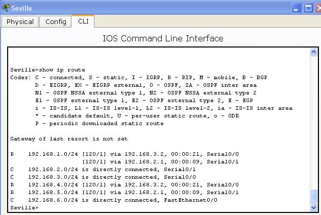
8 Q 7.3.1a Run show ip route on all three routers and record the results Albuquerque>show ip route Codes: C - connected, S - static, I - IGRP, R - RIP, M - mobile, B - BGP D - EIGRP, EX - EIGRP external, O - OSPF, IA - OSPF inter area N1 - OSPF NSSA external type 1, N2 - OSPF NSSA external type 2 E1 - OSPF external type 1, E2 - OSPF external type 2, E - EGP i - IS-IS, L1 - IS-IS level-1, L2 - IS-IS level-2, ia - IS-IS inter area * - candidate default, U - per-user static route, o - ODR P - periodic downloaded static route Gateway of last resort is not set /24 is subnetted, 3 subnets C is directly connected, FastEthernet0/0 C is directly connected, Serial0/0 C is directly connected, Serial0/1 Albuquerque> Yosemite>show ip route Codes: C - connected, S - static, I - IGRP, R - RIP, M - mobile, B - BGP D - EIGRP, EX - EIGRP external, O - OSPF, IA - OSPF inter area N1 - OSPF NSSA external type 1, N2 - OSPF NSSA external type 2 E1 - OSPF external type 1, E2 - OSPF external type 2, E - EGP i - IS-IS, L1 - IS-IS level-1, L2 - IS-IS level-2, ia - IS-IS inter area * - candidate default, U - per-user static route, o - ODR P - periodic downloaded static route Gateway of last resort is not set /24 is subnetted, 3 subnets C is directly connected, FastEthernet0/0 C is directly connected, Serial0/0 C is directly connected, Serial0/1 Yosemite> Seville>show ip route Codes: C - connected, S - static, I - IGRP, R - RIP, M - mobile, B - BGP D - EIGRP, EX - EIGRP external, O - OSPF, IA - OSPF inter area N1 - OSPF NSSA external type 1, N2 - OSPF NSSA external type 2 E1 - OSPF external type 1, E2 - OSPF external type 2, E - EGP i - IS-IS, L1 - IS-IS level-1, L2 - IS-IS level-2, ia - IS-IS inter area * - candidate default, U - per-user static route, o - ODR P - periodic downloaded static route Gateway of last resort is not set /24 is subnetted, 3 subnets C is directly connected, FastEthernet0/0 C is directly connected, Serial0/1 C is directly connected, Serial0/0 Seville> Add Static Routes Execute the commands in example 14-3 (textbook, p.443). Q 7.3.2a Add static routes to Albuquerque, Yosemite, and Seville. Run show ip route and record the results.

9 Albuquerque configuration commands: COMMAND RESULT DESCRIPTION enter Albuquerque> Now in user EXEC mode. enable Albuquerque# Now in privileged EXEC mode. conf t ip route ip route Enter configuration commands, one per line. End with CNTL/Z. Albuquerque(config)# Albuquerque(config)# Albuquerque(config)# %SYS-5-CONFIG_I: Configured from console by console Albuquerque# Albuquerque con0 is now available Press RETURN to get started Instructions for entering commands and ing when finished. Now in global configuration mode. Static route from Albuquerque router to Sam ( ) via Yosemite router serial interface S0/0/1 ( ). Static route from Albuquerque router to Elmer ( ) via Seville router serial interface S0/0/1 ( ). Current configuration information. Exit global configuration mode. Now in privileged EXEC mode. Exit console connection. return Albuquerque> Now in user EXEC mode. show ip route (see below) Note: In textbook Example 14-3 and below, the IP address listed for the Seville router serial connection to Albuquerque is In the textbook, however, the network topology on page 440 shows the IP address the address to be The IP Addresses I used for are those from the network topology diagram ( instead of ) on page 440 in the textbook. Albuquerque show ip route results - Three connected routes, two static routes:

10 Yosemite configuration commands: COMMAND RESULT DESCRIPTION enter Yosemite> Now in user EXEC mode. enable Yosemite# Now in privileged EXEC mode. conf t ip route ip route Enter configuration commands, one per line. End with CNTL/Z. Yosemite(config)# Yosemite(config)# Yosemite(config)# %SYS-5-CONFIG_I: Configured from console by console Yosemite# Yosemite con0 is now available Press RETURN to get started. Instructions for entering commands and ing when finished. Now in global configuration mode. Static route from Yosemite router to Bugs ( ) via Albuquerque router serial interface S0/0/1 ( ). Static route from Yosemite router to Elmer ( ) via Seville router serial interface S0/1/0 ( ). Current configuration information. Exit global configuration mode. Now in privileged EXEC mode. Exit console connection. return Yosemite> Now in user EXEC mode. show ip route (see below) Yosemite show ip route results - Three connected routes, two static routes:

11 Seville configuration commands: COMMAND RESULT DESCRIPTION enter Seville> Now in user EXEC mode. enable Seville# Now in privileged EXEC mode. conf t ip route ip route Enter configuration commands, one per line. End with CNTL/Z. Seville(config)# Seville(config)# Seville(config)# %SYS-5-CONFIG_I: Configured from console by console Seville# Seville con0 is now available Press RETURN to get started. Instructions for entering commands and ing when finished. Now in global configuration mode. Static route from Seville router to Bugs ( ) via Albuquerque router serial interface S0/1/0 ( ). Static route from Seville router to Sam ( ) via Yosemite router serial interface S0/1/0 ( ). Current configuration information. Exit global configuration mode. Now in privileged EXEC mode. Exit console connection. return Seville> Now in user EXEC mode. show ip route (see below) Seville show ip route results - Three connected routes, two static routes:
. COMMAND RESULT DESCRIPTION enter Albuguerque> Now in user EXEC mode.")
12 7.3.3 Add Default Routes The following packet tracer file/topology was used for 7.3.3: If is the IP address of your ISP router, you can forward all packets toward in order to connect to Internet. Execute the commands in example 14-5 (textbook, p. 447). COMMAND RESULT DESCRIPTION enter Albuguerque> Now in user EXEC mode. enable Albuguerque# Now in privileged EXEC mode. conf t ip route Enter configuration commands, one per line. End with CNTL/Z. Albuguerque(config)# Albuguerque(config)# Albuquerque# %SYS-5-CONFIG_I: Configured from console by console Albuquerque con0 is now available Press RETURN to get started. Instructions for entering commands and ing when finished. Now in global configuration mode. Default route from Albuquerque router to unknown IP addresses ( with mask) via ISP router Serial0/0 ( ). Exit global configuration mode. Now in privileged EXEC mode. Current configuration information. Exit console connection. return Albuquerque> Now in user EXEC mode. show ip route (see below) Q 7.3.3a: Run show ip route and record the results. Three connected routes indicated by code C. One static route indicated by code S. * next to S indicates that this is the default route if a path is not found in the routing table is also listed as gateway of last resort.
13 7.3.4 Remove Static Routes Execute the commands to remove static routes in Albuquerque Albuquerque#conf t Albuquerque(config)#no ip route Albuquerque(config)#no ip route Albuquerque(config)#^Z Albuquerque#show ip route Q 7.3.4a Remove static routes in Yosemite and Seville. Run show ip route and record results.
#router rip Albuquerque (config-router)#version 2 Albuquerque (config-router)#network 192.")
14 7.3.5 Implement Dynamic Routing with RIP Please change routers IP addresses based on the table below: Router Serial 0/0 Serial 0/1 FastEthernet0/0 Albuquerque / / /24 Yosemite / / /24 Seville / / /24 Execute the following commands: Albuquerque (config)#router rip Albuquerque (config-router)#version 2 Albuquerque (config-router)#network Albuquerque (config-router)#network Albuquerque (config-router)#network Albuquerque (config-router)#^z Yosemite(config)#router rip Yosemite(config-router)#version 2 Yosemite(config-router)# network Yosemite(config-router)# network Yosemite(config-router)# network Yosemite(config-router)#^Z Seville (config)#router rip Seville (config-router)#version 2 Seville (config-router)# network Seville (config-router)# network Seville (config-router)# network Seville (config-router)#^z


15 Q 7.3.5a: Run show ip route on all routers and record the results. Susan Ferdon, EDTECH 552 SP11
16
TELECOMMUNICATION MANAGEMENT AND NETWORKS
 QUAID-E-AWAM UNIVERSITY OF ENGINEERING SCIENCE AND TECHNOLOGY, NAWABSHAH TELECOMMUNICATION MANAGEMENT AND NETWORKS LAB # 3 CONFIGURING INTERFACES OF ROUTER AND SWITCH Topology Diagram Addressing Table
KIM DONNERBORG / RTS. Cisco Lab Øvelse Af Kim Donnerborg / RTS. Side 0 af 8
 KIM DONNERBORG / RTS Side 0 af 8 INDHOLDSFORTEGNELSE Lab: Basic Router Configuration... 2 Topology Diagram... 2 Addressing Table... 2 Learning Objectives... 2 Scenario... 2 Task 1: Cable the Network....
Lab Configuring OSPF Timers 2500 Series
 Lab 2.3.5 Configuring OSPF Timers 2500 Series Objective Setup an IP addressing scheme for OSPF area. Configure and verify OSPF routing. Modify OSPF interface timers to adjust efficiency of network. Background/Preparation
Lab Configuring OSPF Authentication 2500 Series
 Lab 2.3.4 Configuring OSPF Authentication 2500 Series Objective Setup an IP addressing scheme for Open Shortest Path First (OSPF) area. Configure and verify OSPF routing. Introduce OSPF authentication
Lab 2.8.1: Basic Static Route Configuration
 Topology Diagram Addressing Table Device Interface IP Address Subnet Mask Default Gateway R1 Fa0/0 172.16.3.1 255.255.255.0 N/A S0/0/0 172.16.2.1 255.255.255.0 N/A Fa0/0 172.16.1.1 255.255.255.0 N/A R2
Lab Configuring IGRP Instructor Version 2500
 Lab 7.3.5 Configuring IGRP Instructor Version 2500 Objective Setup IP an addressing scheme using class C networks. Configure IGRP on routers. Background/Preparation Cable a network similar to the one in
Lab VTY Restriction Instructor Version 2500
 Lab 11.2.6 VTY Restriction Instructor Version 2500 NOTE: The loopback entry in this graphic is not required in the lab. Objective Scenario Use the access-class and line commands to control Telnet access
How to Configure a Cisco Router Behind a Non-Cisco Cable Modem
 How to Configure a Cisco Router Behind a Non-Cisco Cable Modem Document ID: 19268 Contents Introduction Prerequisites Requirements Components Used Conventions Configure Network Diagram Configurations Verify
Lab Troubleshooting Routing Issues with show ip route and show ip protocols Instructor Version 2500
 Lab 9.3.5 Troubleshooting Routing Issues with show ip route and show ip protocols Instructor Version 2500 Objective Use the show ip route and show ip protocol commands to diagnose a routing configuration
This document is exclusive property of Cisco Systems, Inc. Permission is granted to print and copy this document for non-commercial distribution and
 This document is exclusive property of Cisco Systems, Inc. Permission is granted to print and copy this document for non-commercial distribution and exclusive use by instructors in the CCNA Exploration:
STUDENT LAB GUIDE CCNA ( )
") STUDENT LAB GUIDE CCNA (640-802) Developed By, Router Infotech Career Academy LAB: 09 Static Route Configuration Objective: To configure & implement Static Route successfully on said devices and test its
STUDENT LAB GUIDE CCNA (640-802) Developed By, Router Infotech Career Academy LAB: 09 Static Route Configuration Objective: To configure & implement Static Route successfully on said devices and test its
Lab Catalyst 2950T and 3550 Series Basic Setup
 Lab 1.2.9.1 Catalyst 2950T and 3550 Series Basic Setup Objective Configure a Cisco Catalyst 2950T or 3550 series Ethernet switch for the first time using the command-line interface (CLI) mode. Basic first
Lab Routing Between an External Router and an Internal Route Processor
 Lab 5.3.4.2 Routing Between an External Router and an Internal Route Processor Objective Scenario The purpose of this lab is to configure routing between an internal route processor and an external router.
Lab Troubleshooting Routing Issues with debug Instructor Version 2500
 Lab 9.3.7 Troubleshooting Routing Issues with debug Instructor Version 2500 Objective Utilize a systematic OSI troubleshooting process to diagnose routing problems. Use various show commands to gather
Routing Information Protocol Version 2.0
 Routing Information Protocol Version 2.0 RIPv2 Objective: onfigure RIPv2 between R1 and R2 to obtain connectivity between Networks Directions onfigure R1's interface F0/0 with the IP address 10.1.0.1/16
This document is exclusive property of Cisco Systems, Inc. Permission is granted to print and copy this document for non-commercial distribution and
 This document is exclusive property of Cisco Systems, Inc. Permission is granted to print and copy this document for non-commercial distribution and exclusive use by instructors in the CCNA Exploration:
Default Gateway Fa0/ N/A. Device Interface IP Address Subnet Mask
 Felix Rohrer Topology Addressing Table Device Interface IP Address Subnet Mask Default Gateway Fa0/1 10.0.0.1 255.255.255.128 N/A S0/0/0 172.16.0.1 255.255.255.252 N/A S0/0/1 172.16.0.9 255.255.255.252
LAB MANUAL for Computer Network
 LAB MANUAL for Computer Network CSE-310 F Computer Network Lab L T P - - 3 Class Work : 25 Marks Exam : 25 MARKS Total : 50 Marks This course provides students with hands on training regarding the design,
เฉลยแล ป Packet Activity
 เฉลยแล ป Packet Activity CCNA LAB 4-4: IP Routing - EIGRP [ต งค าท Ranet HQ (คล กท เคร อง console)] : (ไปย งแท บ Desktop > คล ก Terminal > กด OK) Ranet-HQ>en Ranet-HQ#conf t Enter configuration commands,
Antonio Cianfrani. Packet Tracer
 Antonio Cianfrani Packet Tracer Packet Tracer (1/2) Packet Tracer? Cisco Packet Tracer is a software able to emulate CISCO networking devices. Packet Tracer features: Allows to create network topologies
Lab Configuring IPv4 Static and Default Routes (Solution)
") (Solution) Topology Addressing Table Device Interface IP Address Subnet Mask Default Gateway R1 G0/1 192.168.0.1 255.255.255.0 N/A S0/0/1 10.1.1.1 255.255.255.252 N/A R3 G0/1 192.168.1.1 255.255.255.0
(Solution) Topology Addressing Table Device Interface IP Address Subnet Mask Default Gateway R1 G0/1 192.168.0.1 255.255.255.0 N/A S0/0/1 10.1.1.1 255.255.255.252 N/A R3 G0/1 192.168.1.1 255.255.255.0
Lab - Troubleshooting Connectivity Issues
 Lab - Troubleshooting Connectivity Issues Topology Addressing Table R1 ISP Objectives Device Interface IP Address Subnet Mask Default Gateway G0/1 192.168.1.1 255.255.255.0 N/A S0/0/0 10.1.1.1 255.255.255.252
SEMESTER 2 Chapter 1 Planning and Cabling a Network V 4.0
 SEMESTER 2 Chapter 1 Planning and Cabling a Network V 4.0 135 points 1.1.1 What are the common components between a router and other computers? CPU RAM ROM Operating System 1.1.1.2 What does a router connect?
RR> RR> RR>en RR# RR# RR# RR# *Oct 2 04:57:03.684: %AMDP2_FE-6-EXCESSCOLL: Ethernet0/2 TDR=0, TRC=0 RR#
 RR> RR> RR>en *Oct 2 04:57:03.684: %AMDP2_FE-6-EXCESSCOLL: Ethernet0/2 TDR=0, TRC=0 term len 0 show run Building configuration... Current configuration : 2568 bytes version 15.4 service timestamps debug
Configure Initial Router Settings on Cisco 4000 Series ISRs
 Configure Initial Router Settings on Cisco 4000 Series ISRs This chapter describes how to perform the initial configuration on Cisco 4000 Series Integrated Services Routers (ISRs). It contains the following
outing and Switching Elective : Le
 Routing and Switching Elective : Lecture Notes Nepal Engineering College Compiled by: Junior Professor: Daya Ram Budhathoki Nepal Engineering college, Changunarayan Chapters covered: Cabling Router Configuration
4(b): Assign the IP address on the Serial interface of Router. Console Cable
: Assign the IP address on the Serial interface of Router. Console Cable") Lab#4 Router Basic IOS 4(a). Router Basic Commands & Configuration 4(b) Assign the IP address on the Serial interface of Router Console Cable R1 PC1 Objectives Be familiar with use of different Configuration
Lab#4 Router Basic IOS 4(a). Router Basic Commands & Configuration 4(b) Assign the IP address on the Serial interface of Router Console Cable R1 PC1 Objectives Be familiar with use of different Configuration
Lab Configuring Per-Interface Inter-VLAN Routing (Solution)
") (Solution) Topology Addressing Table Objectives Device Interface IP Address Subnet Mask Default Gateway R1 G0/0 192.168.20.1 255.255.255.0 N/A G0/1 192.168.10.1 255.255.255.0 N/A S1 VLAN 10 192.168.10.11
(Solution) Topology Addressing Table Objectives Device Interface IP Address Subnet Mask Default Gateway R1 G0/0 192.168.20.1 255.255.255.0 N/A G0/1 192.168.10.1 255.255.255.0 N/A S1 VLAN 10 192.168.10.11
Lab Configuring Static Routes Instructor Version 2500
 Lab 6.1.6 Configuring Static Routes Instructor Version 2500 Objective Configure static routes between routers to allow data transfer between routers without the use of dynamic routing protocols. Background/Preparation
Lab: Basic Static Route Configuration
 Lab: Basic Static Route onfiguration Topology Diagram Addressing Table Device Interface IP Address Subnet Mask Default Gateway R1 Fa0/0 172.16.3.1 255.255.255.0 N/A S0/0/0 172.16.2.1 255.255.255.0 N/A
Lab Configuring Per-Interface Inter-VLAN Routing (Instructor Version)
") (Instructor Version) Instructor Note: Red font color or Gray highlights indicate text that appears in the instructor copy only. Topology Addressing Table Objectives Device Interface IP Address Subnet Mask
(Instructor Version) Instructor Note: Red font color or Gray highlights indicate text that appears in the instructor copy only. Topology Addressing Table Objectives Device Interface IP Address Subnet Mask
Lab Configuring Static NAT
 Lab 10.5.1 Configuring Static NAT Objective Configure Network Address Translation (NAT) static translation to provide reliable outside access to three shared company servers. Scenario Step 1 The International
Lab b Simple DMZ Extended Access Lists Instructor Version 2500
 Lab 11.2.3b Simple DMZ Extended Access Lists Instructor Version 2500 Objective In this lab, the use of extended access lists to create a simple DeMilitarized Zone (DMZ) will be learned. 372-833 CCNA 2:
Basic Router Configuration
 This section includes information about some basic router configuration, and contains the following sections: Default Configuration, on page 1 Configuring Global Parameters, on page 2 Configuring Gigabit
ROUTE Lab Guide Labs powered by
 OUTE Lab Guide 300-101 ii OUTE 300-101 Lab Guide LM20170908/BV1.0 iii 25 C e n tur y Blvd., S te. 5 0 0, N a s hvill e, T N 37214 B o s o n.c o m To perform the labs referenced in this book, please download
Chapter 6: Network Layer
 Chapter 6: Network Layer Introduction to Networks Intro to Networks v5 Network Layer Intro to Networks v5 2 The Network Layer End to End Transport processes Addressing end devices Encapsulation of Packets
CIS 83 LAB 2 - Single Area OSPF Rich Simms September 12, Objective. Scenario. Topology
 CIS 83 LAB 2 - Single Area OSPF Rich Simms September 12, 2006 Objective The objective of this lab is to become familiar setting up and configuring OSPF on three routers for a single area. OSPF is our first
Do I Know This Already? Quiz What command brings up an interface that previously was administratively disabled?
 Do I Know This Already? Quiz 365 4. What command brings up an interface that previously was administratively disabled? a. no shutdown b. shutdown c. enable d. up e. no disable f. disable 5. Imagine that
Hochschule Bremen Networking Lab
 Hochschule Bremen Networking Lab User Manual Welcome to the Hochschule Bremen networking lab. This manual will give you a brief introduction on how to use the PCs and networking hardware in the lab. The
Password Recovery Procedure for the Cisco 3600 and 3800 Series Routers
 Password Recovery Procedure for the Cisco 3600 and 3800 Series Routers Document ID: 22189 Contents Introduction Prerequisites Requirements Components Used Related Products Conventions Step by Step Procedure
Lab 1.1.4c Configuring Static NAT Addresses
 Lab 1.1.4c Configuring Static NAT Addresses Objective Configure a router to use network address translation (NAT) to convert internal IP addresses, typically private addresses, into outside public addresses.
Lab Verifying NAT and PAT Configuration
 Lab 1.1.5 Verifying NAT and PAT Configuration Objective Configure a router for Network Address Translation (NAT) and Port Address Translation (PAT) Test the configuration and verify NAT/PAT statistics
Lab 5: Inter-VLANs Routing
 Lab 5: Inter-VLANs Routing Network Topology:- Device Interface IP Address Subnet Mask Gateway/Clock Rate Fa 0/0.10 10.5.0.1 255.255.255.192 ----- R1 Fa 0/0.20 10.6.0.1 255.255.255.192 ----- Fa 0/0.30 10.10.0.1
Packet Tracer - Configuring Initial Switch Settings
 Topology Objectives Part 1: Verify the Default Switch Configuration Part 2: Configure a Basic Switch Configuration Part 3: Configure a MOTD Banner Part 4: Save Configuration Files to NVRAM Part 5: Configure
Lab 7 Configuring Basic Router Settings with IOS CLI
 Lab 7 Configuring Basic Router Settings with IOS CLI Objectives Part 1: Set Up the Topology and Initialize Devices Cable equipment to match the network topology. Initialize and restart the router and switch.
Lab- Troubleshooting Basic EIGRP for 1Pv4
 Lab- Troubleshooting Basic EIGRP for 1Pv4 Topology G0/0 G0/0 PC-A PC-C 2013 Cisco and/or its affiliates. All rights reserved. This document is Cisco Public. Page 1 of 27 Addressing Table efault Gateway
OSPF single area configuration lab on packet tracer
 OSPF single area configuration lab on packet tracer This OSPF lab is created in packet tracer and you will learn the OSPF single area configuration from this lab. Configuring the OSPF Routing Process This
Lab Configuring Router Passwords. Objective. Background/Preparation. Step 1 Login to the router in user EXEC mode
 Lab 3.1.3 Configuring Router Passwords Objective Configure a password for console login to user EXEC mode. Configure a password for virtual terminal (Telnet) sessions. Configure a secret password for privileged
CIS 83 LAB 3 - EIGRP Rich Simms September 23, Objective. Scenario. Topology
 CIS 83 LAB 3 - EIGRP Rich Simms September 23, 2006 Objective The objective of this lab is to become familiar setting up and configuring EIGRP on three routers. EIGRP is a Cisco proprietary distance-vector
LAB MANUAL for Computer Network
 LAB MANUAL for Computer Network This course provides students with hands on training regarding the design, troubleshooting, modeling and evaluation of computer networks. In this course, students are going
Lab Establishing and Verifying a Telnet Connection Instructor Version 2500
 Lab 4.2.2 Establishing and Verifying a Telnet Connection Instructor Version 2500 Objective Establish a Telnet connection to a remote router. Verify that the application layer between source and destination
Shooting Trouble with IP
 C H A P T E R 3 Shooting Trouble with IP This chapter focuses on a number of objectives falling under the CCNP Troubleshooting guidelines. Understanding basic TCP/IP troubleshooting principles not only
Lab Router Configuration Using Setup Instructor Version 2500
 Lab 2.2.1 Router Configuration Using Setup Instructor Version 2500 Objective Use the System Configuration dialog (setup). Establish some basic router configurations. Background/Preparation A new router
Route between VLANs using a 3560 switch with an internal route processor using Cisco Express Forwarding (CEF).
.") Lab 3- Part I Inter-VLAN routing with a Multilayer Switch Configuration and Management of Networks - 2014 Topology Objective Route between VLANs using a 3560 switch with an internal route processor using
Lab 3- Part I Inter-VLAN routing with a Multilayer Switch Configuration and Management of Networks - 2014 Topology Objective Route between VLANs using a 3560 switch with an internal route processor using
Lab 1.1.4a Configuring NAT
 Lab 1.1.4a Configuring NAT Objective Configure a router to use network address translation (NAT) to convert internal IP addresses, typically private addresses, into outside public addresses. Background/Preparation
Building the Routing Table. Introducing the Routing Table Directly Connected Networks Static Routing Dynamic Routing Routing Table Principles
 Building the Routing Table Introducing the Routing Table Directly Connected Networks Static Routing Dynamic Routing Routing Table Principles Introducing the Routing Table R1# show ip route Codes: C - connected,
PT Activity: Configure AAA Authentication on Cisco Routers
 PT Activity: Configure AAA Authentication on Cisco Routers Instructor Version Topology Diagram Addressing Table Device Interface IP Address Subnet Mask R1 Fa0/0 192.168.1.1 255.255.255.0 S0/0/0 10.1.1.2
Packet Tracer - Connect a Router to a LAN (Instructor Version)
") (Instructor Version) Instructor Note: Red font color or gray highlights indicate text that appears in the instructor copy only. Topology Addressing Table Device Interface IP Address Subnet Mask Default
(Instructor Version) Instructor Note: Red font color or gray highlights indicate text that appears in the instructor copy only. Topology Addressing Table Device Interface IP Address Subnet Mask Default
Cisco IOS Configuration Basics
 Cisco IOS Configuration Basics Switching Router Overview Router configuration controls the operation of the router s: Interface IP address and netmask Routing information (static, dynamic or default) Boot
Lab 5-1 Hot Standby Router Protocol
 Lab 5-1 Hot Standby Router Protocol Topology Diagram Objective Configure inter-vlan routing with HSRP to provide redundant, fault tolerant routing to the internal network. Scenario Step 1 HSRP provides
Layer3 VPN with OSPF Protocol between CE-PE
 MPLS Layer3 VPN with OSPF Protocol between CE-PE Disclaimer This Configuration Guide is designed to assist members to enhance their skills in particular technology area. While every effort has been made
Student Instructions: "Rob Router" Learns How to Communicate...Again!
 Student Instructions: "Rob Router" Learns How to Communicate...Again! PART 1 Perform the following tasks: Configure the router assigned to you. (Use the Router Configuration Setup handout.) When finished
Lab Configuring 802.1Q Trunk-Based Inter-VLAN Routing (Instructor Version Optional Lab)
") (Instructor Version Optional Lab) Instructor Note: Red font color or gray highlights indicate text that appears in the instructor copy only. Optional activities are designed to enhance understanding and/or
(Instructor Version Optional Lab) Instructor Note: Red font color or gray highlights indicate text that appears in the instructor copy only. Optional activities are designed to enhance understanding and/or
First-Time Configuration
 This chapter describes the actions to take before turning on your router for the first time Setup Mode, on page 1 Verifying the Cisco IOS Software Version, on page 4 Configuring the Hostname and Password,
Lab 1. CLI Navigation. Scenario. Initial Configuration for R1
 Lab 1 CLI Navigation This lab covers the most basic skills for accessing and using the command-line interface (CLI) on a Cisco router or switch. Many of the small, picky details of how the CLI works cannot
RealCiscoLAB.com. Configure inter-vlan routing with HSRP to provide redundant, fault-tolerant routing to the internal network.
 RealCiscoLAB.com CCNPv6 SWITCH Hot Standby Router Protocol Topology Objective Background Configure inter-vlan routing with HSRP to provide redundant, fault-tolerant routing to the internal network. Hot
ord Recovery Procedure for the Cisco Catalyst 8510 Multiserv
 ord Recovery Procedure for the Cisco Catalyst 8510 Multiserv Table of Contents Password Recovery Procedure for the Cisco Catalyst 8510 Multiservice Switch Router...1 Introduction...1 Before You Begin...1
Configuring Redundant Routing on the VPN 3000 Concentrator
 Configuring Redundant Routing on the VPN 3000 Concentrator Document ID: 13354 Contents Introduction Prerequisites Requirements Components Used Conventions Configure Network Diagram Router Configurations
This document is exclusive property of Cisco Systems, Inc. Permission is granted to print and copy this document for non-commercial distribution and
 This document is exclusive property of Cisco Systems, Inc. Permission is granted to print and copy this document for non-commercial distribution and exclusive use by instructors in the CCNA 2: Routers
Password Recovery Procedure for the Cisco 1700 and 1800 Series Routers
 Password Recovery Procedure for the Cisco 1700 and 1800 Series Routers Document ID: 22187 Introduction Prerequisites Requirements Components Used Related Products Conventions Step by Step Procedure Example
co Password Recovery Procedure for the Cisco 1700 Series R
 co Password Recovery Procedure for the Cisco 1700 Series R Table of Contents Password Recovery Procedure for the Cisco 1700 Series Routers...1 Introduction...1 Before You Begin...2 Conventions...2 Prerequisites...2
Introduction To Cisco IOS
 S SRS CNS Lab2 IntroductionToCiscoIOS IntroductionToCiscoIOS 1 RouterArchitecture Ciscoroutershavemanysimilaritieswithpersonalcomputers.Afterall,mostoperating systems offer basic routing features to any
Cisco Network Academy CCNA 1 Introduction to Networks
 Cisco Network Academy CCNA 1 Introduction to Networks Packet Tracer Practice with Dans Sample http://www.danscourses.com/ In this lab, you will learn how to configure the following tasks: IPv4 Addressing
Lab Troubleshooting IP Address Issues Instructor Version 2500
 Lab 4.2.6 Troubleshooting IP Address Issues Instructor Version 2500 Objective Configure two routers and two workstations in a small WAN. Troubleshoot problems introduced by incorrect configurations. Background/Preparation
CCNA Exploration: Routing Protocols and Concepts Chapter 8 Case Study
 Objectives: Consolidate routing table reading skills. Introduce the idea of more than 1 routing protocol running into the same router. Explain the use of routes to Null0 interface. Intro: Connex Inc. is
Before you start the lab exercises see the lab administrator or EEE3080F tutor to get assigned to your routers.
 EEE00F Lab Basics of the Network Lab Student Lab Manual Before you start the lab exercises see the lab administrator or EEE00F tutor to get assigned to your routers. Contents. Resources used in the labs...
Lab Backing up Configuration Files Instructor Version 2500
 Lab 3.2.9 Backing up Configuration Files Instructor Version 2500 Objective Demonstrate the capture of the running configuration of a router to an ASCII text file with HyperTerminal. Edit or modify the
EIGRP Lab / lo1. .1 lo / /30
 EIGRP Lab 172,16,1.0/24.1 lo1 192.168.20.0/30.2.1 Merida fa0 fa0 Vargas lo2.1 lo2.5.1 lo1 192.168.30.0/24 172.16.2.0/24 192.168.20.4.0/30 Scenario: Loopback0 is used for RouterID Loopback1 is a virtual
PT Activity 4.4.1: Basic VTP Configuration
 Topology Diagram Addressing Table Device Interface IP Address Subnet Mask Default Gateway S1 VLAN 99 172.17.99.11 255.255.255.0 N/A S2 VLAN 99 172.17.99.12 255.255.255.0 N/A S3 VLAN 99 172.17.99.13 255.255.255.0
LAB8: OSPF IPv4. OSPF: Virtual Link. Disclaimer
 Page1 AB8: OSPF IPv4 Disclaimer This onfiguration Guide is designed to assist members to enhance their skills in respective technology area. While every effort has been made to ensure that all material
This document is exclusive property of Cisco Systems, Inc. Permission is granted to print and copy this document for non-commercial distribution and
 This document is exclusive property of Cisco Systems, Inc. Permission is granted to print and copy this document for non-commercial distribution and exclusive use by instructors in the CCNA Exploration:
Network Cable : Configure & Verifying Cross-Over Cable. Network Profile: Network Discovery, File and Printer sharing
 Lab # Lab 1 Lab 2 Lab 3 Lab 4 Lab 5 Lab 6 Lab 7 Lab 8 Lab 9 Lab 10 Lab 11 Lab 12 Lab 13 Lab 14 Lab 15 Lab 16 Lab 17 Lab 18 Lab 19 Lab 20 Lab 21 Lab 22 Lab 23 Topic LAN Card: Check Speed, Enable/Disable.
IP Routing Configuration in a Router with Troubleshooting
 International Journal of Electronics and Computer Science Engineering 93 Available Online at www.ijecse.org ISSN-2277-1956 IP Routing Configuration in a Router with Troubleshooting 1 Gyan Prakash Pal,
Lab Configuring Basic Router Settings with IOS CLI (Instructor Version Optional Lab)
") (Instructor Version Optional Lab) Instructor Note: Red font color or gray highlights indicate text that appears in the instructor copy only. Optional activities are designed to enhance understanding and/or
(Instructor Version Optional Lab) Instructor Note: Red font color or gray highlights indicate text that appears in the instructor copy only. Optional activities are designed to enhance understanding and/or
This document is exclusive property of Cisco Systems, Inc. Permission is granted to print and copy this document for non-commercial distribution and
 This document is exclusive property of Cisco Systems, Inc. Permission is granted to print and copy this document for non-commercial distribution and exclusive use by instructors in the CCNA Exploration:
Access Server Dial In IP/PPP Configuration With Dedicated V.120 PPP
 Access Server Dial In IP/PPP Configuration With Dedicated V.120 PPP Document ID: 6306 Contents Introduction Prerequisites Requirements Components Used Conventions Background Information How V.120 Affects
Chapter 8: Lab B: Configuring a Remote Access VPN Server and Client
 Chapter 8: Lab B: Configuring a Remote Access VPN Server and Client Topology IP Addressing Table Device Interface IP Address Subnet Mask Default Gateway Switch Port R1 FA0/1 192.168.1.1 255.255.255.0 N/A
Configuring the Cisco IOS MGCP Gateway
 Configuring the Cisco IOS MGCP Gateway Document ID: 42105 Contents Introduction Prerequisites Requirements Components Used Conventions Tasks to Perform Step by Step Summary Configurations Troubleshooting
Lab Hot Standby Router Protocol
 Lab 6.5.1 Hot Standby Router Protocol Objective Scenario Step 1 Step 2 Configure Hot Standby Router Protocol (HSRP) on a pair of routers to provide redundant router services to a network. Two routers are
Lab Configuring a Serial Interface
 Lab 3.1.5 Configuring a Serial Interface Objective Configure a serial interface on each of two routers so they can communicate. Background/Preparation Any router that meets the interface requirements may
Lab - Configuring a Switch Management Address
 Topology Addressing Table Objectives Device Interface IP Address Subnet Mask Default Gateway S1 VLAN 1 192.168.1.2 255.255.255.0 N/A PC-A NIC 192.168.1.10 255.255.255.0 N/A Part 1: Configure a Basic Network
Case Study 2: Frame Relay and OSPF Solution
 Case Study 2: Frame Relay and OSPF Solution Objective In this case study, you troubleshoot a complex scenario involving Frame Relay and Open Shortest Path First (OSPF). Figure 2-1 shows the topology for
Lab Securing Network Devices
 Topology Addressing Table Objectives Device Interface IP Address Subnet Mask Default Gateway R1 G0/1 192.168.1.1 255.255.255.0 N/A S1 VLAN 1 192.168.1.11 255.255.255.0 192.168.1.1 PC-A NIC 192.168.1.3
Chapter 7 Lab 7-1, Configuring BGP with Default Routing
 Chapter 7 Topology Objectives Configure BGP to exchange routing information with two ISPs. Background The International Travel Agency (ITA) relies extensively on the Internet for sales. For this reason,
Network Layer Week 5. Module : Computer Networks Lecturer: Lucy White Office : 324
 Network Layer Week 5 Module : Computer Networks Lecturer: Lucy White lbwhite@wit.ie Office : 324 1 Network Layer Network Layer Protocols Common Network Layer Protocols Internet Protocol version 4 (IPv4)
Lab Troubleshooting RIP
 Lab 7.2.6 Troubleshooting RIP Objective Set up an IP addressing scheme using class B networks. Configure RIP on routers. Observe routing activity using the debug ip rip command. Examine routes using the
Lab : Challenge OSPF Configuration Lab. Topology Diagram. Addressing Table. Default Gateway. Device Interface IP Address Subnet Mask
 Topology Diagram Addressing Table Device Interface IP Address Subnet Mask Default Gateway Fa0/0 HQ S0/0/0 S0/0/1 Lo1 10.10.10.1 255.255.255.252 Fa0/0 Branch1 S0/0/0 S0/0/1 Fa0/0 Branch2 S0/0/0 S0/0/1 PC1
Chapter 7 Lab 7-2, Using the AS_PATH Attribute
 Chapter 7 Topology Objectives Use BGP commands to prevent private AS numbers from being advertised to the outside world. Use the AS_PATH attribute to filter BGP routes based on their source AS numbers.
Chapter 3 Lab 3-4, OSPF over Frame Relay
 Chapter 3 Lab 3-4, OSPF over Frame Relay Topology Objectives Background Configure OSPF over Frame Relay. Use non-broadcast and point-to-multipoint OSPF network types. Modify default OSPF timers. You are
ASA Has High CPU Usage Due to a Traffic Loop When VPN Clients Disconnect
 ASA Has High CPU Usage Due to a Traffic Loop When VPN Clients Disconnect Contents Introduction Prerequisites Requirements Components Used Background Information Problem: Packets Destined for a Disconnected