Verification of Cyber-Physical Controller Software Using the AVM Meta Tool Suite and HybridSAL
|
|
|
- Kerry Daniel
- 5 years ago
- Views:
Transcription
, Ashish Tiwari (ashish.tiwari@sri.com), and Xenofon Koutsoukos (xenofon.koutsoukos@vanderbilt.")
1 Verification of Cyber-Physical Controller Software Using the AVM Meta Tool Suite and HybridSAL Joseph Porter Ashish Tiwari and Xenofon Koutsoukos S5 Symposium June 2014
2 Controller Design Design space exploration with simulation can answer early questions about controller choices Simulation over alternatives is much cheaper than building prototypes Automated DSE helps answer questions about the evolving design Formal verification tools can detect hard-to-find errors Testing may fail to detect (large scenario space) Requires property specification CyPhy enables easy property addition, model editing, and visualize verification results


3 OpenMETA-CyPhy Cyber Toolchain (DARPA AVM) Cyber Components Authoring System Design Space Authoring Physical Components Authoring Custom Components Simulink/ Stateflow Auto Import Verification Condition Generation * Cyber Modeling Language Cyber Code Generator Component Use CyPhy System Design / Design Space Cyber Components Dynamics TB CyPhy Modelica Composer Physical Components Verification TB Component Use Dymola/ OpenModelica C2M2L Components Hybrid System Evaluation Cyber XML Modelica Sim (.mo,.lib) Modelica Simulation DAE XML HybridSAL Formal Verification
4 Why Cyber Modeling? Everything has software cars, refrigerators, even chainsaws. How do we model controller software and combine it with the mechanical design? Keep the design processes for the physical and cyber in sync. Building and testing prototypes is expensive. Integrating controllers into mechanical designs is costly and time-consuming. Too many scenarios to test cyber and physical systems exhaustively. Testing will miss important cases. Some examples: Toyota Acceleration problem MARS polar lander Ariane 5
5 AVM Control Design Capabilities How are META Cyber capabilities different from designing and simulating controllers using Modelica or Simulink alone? 1. Cyber controller component in Modelica is not a simulation model, but is the actual embedded code scheduled by a discrete-time periodic sampler. The simulation is much more realistic. 2. Integrated formal hybrid verification toolchain. 3. All of the benefits of using CyPhyML: design space exploration curated component library integrated test bench models parametric exploration cloud-based simulation
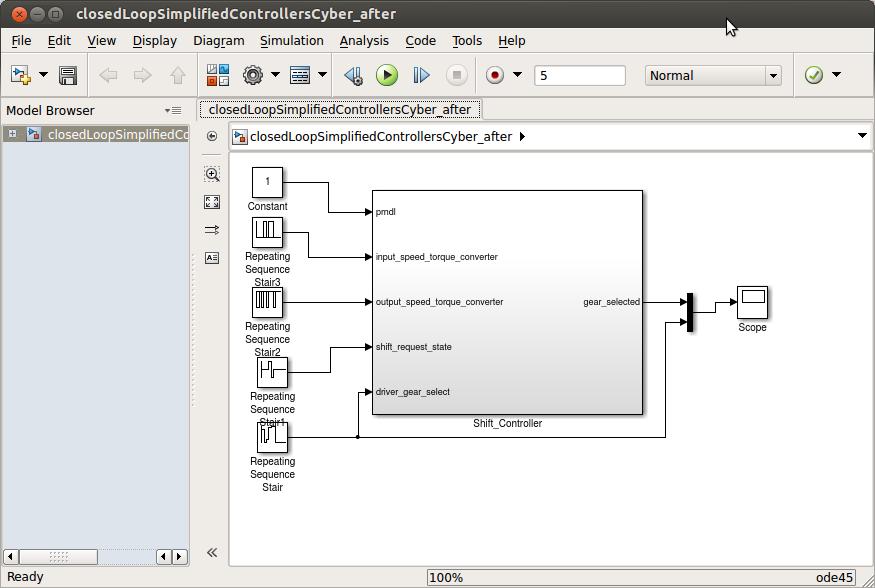
6 Introduction We will show how the Cyber tools can integrate multiple transmission controllers modeled in Simulink/Stateflow with a Driveline modeled in Modelica. We will use DSE to assess the controller alternatives in simulation, and then verify the candidate controller. Scenario: If we have a cheaper fixed-point processor, will the controller performance be degraded?
7 Creating a CyPhy model The CyPhy model is the integration model. It contains: The imported Modelica model (The System) The interface to the Cyber model (The Controller) A design describing how the two are connected A test bench describing how to evaluate the design


8 Connecting the Cyber interface to the system model in GME All modern designs have software controllers. How do we incorporate them into a design?
9 CyPhyML Controller Composition Concepts AVM Component Interface (Dynamics) Physical Component Connectors Parameters Modelica Component Interface S V B Modelica Component Signals (causal) P Physical variables (acausal) Buses (aggregate) Parameters Modelica Components and Ports each have a Class string indicating the location of its type definition in the library. C2M2L_Ext.Interfaces.Context_Interfaces.Driver.Driver_Bus
10 CyPhyML Controller Composition Concepts AVM Component Interface (Dynamics) Physical Component Connectors Parameters Modelica Component Interface S V B Modelica Component Signals (causal) P Physical variables (acausal) Buses (aggregate) Parameters Modelica Components and Ports each have a Class string indicating the location of its type definition in the library: C2M2L_Ext.Interfaces.Context_Interfaces.Driver.Driver_Bus
11 CyPhyML Controller Composition Concepts Component Physical Component S V Modelica Component B B P In composition, the underlying port types must match exactly (by type string). Modelica Components and Ports each have a Class string indicating the location of its type definition in the library. C2M2L_Ext.Interfaces.Context_Interfaces.Driver.Driver_Bus

12 CyPhyML Controller Composition Concepts Controller Component Physical Component S X S V Modelica Component B B P P Parameter ports are exposed in assemblies and test benches. Parameter values are propagated down into the components. Controller components must be causal: Only connect to signals and bus ports containing signals. Physical variable ports can not be connected to controller components.
 Cyber interface parameters refer directly to parameter objects deep in the Simulink hierarchy. AVM and Cyber component model interfaces are identical.")
13 CyPhyML Controller Composition Concepts Controller Component Physical Component Cyber Component (refers to external Cyber model) Simulink P S S S S B P S B P X S V B P Modelica Component (refers to external model in Modelica component libraries) Cyber interface parameters refer directly to parameter objects deep in the Simulink hierarchy. AVM and Cyber component model interfaces are identical. Bus ports aggregate signals. Bus signals are identified by name. Only one component can produce (output) a bus signal. The others must consume it.


14 Translating controllers to the Cyber language Controllers in Simulink/Stateflow Controllers in GME Cyber language Shift controller MDL2MGA Translator Torque converter controller Torque reduction controller


15 Design Space Exploration DSE allows us to evaluate different controller variants, to compare performance.
16 Controller Models Dynamics Models META-Cyber Simulation Workflow Simulink/ Stateflow 4 Controller Components Controller Import CyberComposition Model (GME) 5 6b Controller Modelica Details Interface 1 Code Generation Modelica Dynamic Components 8b Generated Code Controller C Code Glue Code Modelica Interface System Modeling Physical Component Import CyPhyML 2 Model (GME) 3 6a Modelica Controller References Design Space Modelica Dynamics References Legend Reference from CyPhyML to an external component model. Model created manually/semiautomatically. Test 7 Bench 8a Automatic model translation step. 9 Modelica Design Simulation Controller Libraries Dynamics Models Generation & Simulation
17 META-Cyber Simulation Workflow 1. Create or obtain physical component models in Modelica. 2. Create a CyPhyML model using GME. 3. Import Modelica components and build the system design space in the CyPhy model. 4. Create your controllers in Simulink/Stateflow. 5. Create a Cyber model in META and import your controllers into this model. 6. Define the controller interface in the CyPhyML model using GME (6a) and link it to the Cyber model (6b). 7. Create a test bench for the design in CyPhyML. 8. From the test bench, run the Master Interpreter to generate Modelica simulation code (8a). The Modelica generator also invokes the code generator to create Modelica controller components which are integrated into the simulation (8b). 9. Run the simulation.


18 Tool Flow Invoke DSE to explore alternatives Test Bench model defines inputs & environment for system under test Designs Component Alternatives DESERT tool presents design choices Select designs to generate Specify component Library paths Generate the Modelica model Simulate the designs and compare


19 Generated Code Generated code is placed in Simulink subdirectory Generated code can be inspected by opening the generated Visual Studio solution file.
20 Alternative #1 Simulation results #1 Selected gear vs time (s) Engine rpm vs time (blue) Transmission output rpm vs time (red)
 Transmission output rpm vs time")
21 Alternative #2 Simulation results #2 Selected gear vs time (s) Engine rpm vs time (blue) Transmission output rpm vs time (red)
22 Controller Correctness Once we have identified our candidate controller, we can use formal verification to assess the controller logic.
23 Formal Verification Testing/simulation can fail to detect design errors that are manifested only under certain scenarios Formal verification can verify designs for all scenarios Formal verification complements simulation in improving confidence in system design
24 Formal Verification What is formal verification? Techniques for verifying the system that are based on symbolic algebra, rather than numerical simulations Achieves the equivalent of exhaustive testing
25 Verification Workflow Identical to the simulation workflow except: Temporal properties are attached to models Verification results, namely o status (pass, fail, or error) and explanation are displayed on the dashboard Controllers often include intricate logic that can be difficult to exhaustively test Apply formal verification to ShiftController here

26 Temporal Properties Properties capture the intent of the controller design ShiftController: Inputs: 1.driver_gear_select 2.shift_request_state 3.input_speed_TC 4.output_speed_TC Output: 1.gear_selected
27 Shift Controller Inputs-Output The input variable driver_gear_select takes values: reverse=1, park=2, swim=3, neutral=4, neutral_pivot=5, low=6, drive=7 The input variable shift_request_state takes values: down_shift=1, no_shift=2, up_shift=3 The output variable gear_selected takes values: 0, 1, 2, 3, 4 A correct controller should guarantee something about the output under certain assumptions on the inputs.
28 Temporal Properties as Specification Some desired properties for such a ShiftController: 1. If shift_request_state==3 (up_shift) and driver_gear_select==7 (drive), then eventually gear_selected==4 (fourth gear) []( srs==3 && dgs==7 => <>(gear==4) ) []( [](srs==3 && dgs==7) => <>(gear==4) ) 2. If dgs==6(low), then eventually gear <= 1 []( [](dgs==6) => <>(gear <= 1) ) []( [](dgs==6) => <>(gear <= 2) )
29 Pattern-based Property Specification All properties above have the same Global Response pattern Another useful pattern is Absence before R Property: The output gear_selected does not take value 4 before driver_gear_select is 7 (drive) P := gear_selected == 4 R := driver_gear_select == 7 Property: P is absent before R

30 Adding LTL Properties to SL/SF Models
, then eventually gear_selected <= 1 (first gear)")
31 Pattern-based Property Specification If driver_gear_select is 6(low), then eventually gear_selected <= 1 (first gear)

32 Viewing Properties in SL/SF Models Set of all properties = Specification of the component
33 The Verification TestBench After controller models have been annotated with desired temporal properties, they are translated into CyberComposition language, and verified SL/SF + Properties CyberComp XML Formal Verification Results Verification results can be viewed in the dashboard

34 Verification Results in the Dashboard
35 Understanding Verification Results 1. If shift_request_state==3 (up_shift) and driver_gear_select==7 (drive), then eventually gear_selected==4 []( srs==3 && dgs==7 => <>(gear==4) ) Violated []( [](srs==3 && dgs==7) => <>(gear==4) ) Verified 2. If dgs==6(low), then eventually gear <= 1 []( [](dgs==1) => <>(gear <= 1) ) Violated []( [](dgs==1) => <>(gear <= 2) ) Verified 3. The event gear_selected==4 is absent before dgs is 7 (drive) Verified
36 Property is False in the Model: Details
37 Simulating the Counter-Example
38 Visualizing the Counter-Example []( [](dgs==6) => <>(gear <= 1) ) Violated
39 Refining the Model or Property When a property is found to be false in the model, the user can view and analyze the counterexample, and based on that, go back to the controller design and fix either The controller Edit transition guards Add/delete transitions The property Make the property weaker Constrain the inputs of the controller
40 Refining the Property Since output variable, gear_selected, gets stuck at value 2, we can see if our controller satisfies a weaker specification. []( [](dgs==6) => <>(gear <= 2) ) Verified

41 Refining the Model Designer changes condition on the downshift transition out of Gear2 in SL/SF
42 Refining the Model The condition on the outgoing transition from state Gear2 to state lockoutd1 is chaged from: srs==1 && dgs!=6 && dgs!=1 && in_tc > out_tc ((srs==1 && dgs!=6 && dgs!=1 && in_tc > out_tc) (dgs==6 dgs==1)) Enable transition additionally when driver_gear_select is 6 (low)
43 Verification Results for the Updated Model

44 Property is True in the Model: Details
 => <>(gear <= 1) )")
45 Old CounterExample on the Fixed Model []( [](dgs==6) => <>(gear <= 1) ) Verified
46 Conclusions Design space exploration with simulation can answer early questions about controller choices Simulation over alternatives is much cheaper than building prototypes Automated DSE helps answer questions about the evolving design Formal verification tools can detect hard-to-find errors Testing may fail to detect (large scenario space) Requires property specification CyPhy enables easy property addition, model editing, and visualize verification results
47 Questions
Institute for Software-Integrated Systems. Technical Report
 Institute for Software-Integrated Systems Technical Report TR#: Title: Authors: ISIS-15-107 Software Design and Implementation in the META Toolchain Sandeep Neema, Ted Bapty and Daniel Balasubramanian
ADAS Virtual Prototyping using Modelica and Unity Co-simulation via OpenMETA
 ADAS Virtual Prototyping using Modelica and Unity Co-simulation via OpenMETA Masahiro Yamaura 1 Nikos Arechiga 1 Shinichi Shiraishi 1 Scott Eisele 2 Joseph Hite 2 Sandeep Neema 2 Jason Scott 2 Theodore
Webinar on Design Automation for Cyber-Physical Systems
 Webinar on Design Automation for Cyber-Physical Systems Richard M. Murray (California Institute of Technology) Alberto Sangiovanni-Vincentelli (University of California at Berkeley) Janos Sztipanovits
M U L T I - M O D E L L A N G U A G E S U I T E F O R C Y B E R P H Y S I C A L S Y S T E MS F I N A L R E P O R T
 M U L T I - M O D E L L A N G U A G E S U I T E F O R C Y B E R P H Y S I C A L S Y S T E MS F I N A L R E P O R T Sandeep Neema, Ted Bapty, Janos Sztipanovits Institute for Software Integrated Systems,
MODEL-BASED VERIFICATION TOOLCHAIN FOR INCREASING TRUST ON AUTOMATED CODE-GENERATORS. Akshay Agrawal. Thesis. Submitted to the Faculty of the
 MODEL-BASED VERIFICATION TOOLCHAIN FOR INCREASING TRUST ON AUTOMATED CODE-GENERATORS By Akshay Agrawal Thesis Submitted to the Faculty of the Graduate School of Vanderbilt University in partial fulfillment
Applications of Program analysis in Model-Based Design
 Applications of Program analysis in Model-Based Design Prahlad Sampath (Prahlad.Sampath@mathworks.com) 2018 by The MathWorks, Inc., MATLAB, Simulink, Stateflow, are registered trademarks of The MathWorks,
CS/ECE 5780/6780: Embedded System Design
 CS/ECE 5780/6780: Embedded System Design John Regehr Lecture 18: Introduction to Verification What is verification? Verification: A process that determines if the design conforms to the specification.
Institute for Software-Integrated Systems. Technical Report
 Institute for Software-Integrated Systems Technical Report TR#: Title: Authors: ISIS-15-104 CyPhyML Language in the META Toolchain Sandeep Neema, Jason Scott and Ted Bapty This research is supported by
Distributed Systems Programming (F21DS1) Formal Verification
 Formal Verification") Distributed Systems Programming (F21DS1) Formal Verification Andrew Ireland Department of Computer Science School of Mathematical and Computer Sciences Heriot-Watt University Edinburgh Overview Focus on
Distributed Systems Programming (F21DS1) Formal Verification Andrew Ireland Department of Computer Science School of Mathematical and Computer Sciences Heriot-Watt University Edinburgh Overview Focus on
Flight Systems are Cyber-Physical Systems
 Flight Systems are Cyber-Physical Systems Dr. Christopher Landauer Software Systems Analysis Department The Aerospace Corporation Computer Science Division / Software Engineering Subdivision 08 November
Semantic Specifications for Domain-Specific Modeling Languages
 Semantic Specifications for Domain-Specific Modeling Languages Gabor Simko Institute for Software Integrated Systems Vanderbilt University Nashville, TN Abstract. While there is a generic agreement that
Administrivia. ECE/CS 5780/6780: Embedded System Design. Acknowledgements. What is verification?
 Administrivia ECE/CS 5780/6780: Embedded System Design Scott R. Little Lab 8 status report. Set SCIBD = 52; (The Mclk rate is 16 MHz.) Lecture 18: Introduction to Hardware Verification Scott R. Little
Qualitative Reasoning with Modelica Models
 Qualitative Reasoning with Modelica Models Matthew Klenk and Johan de Kleer and Daniel G. Bobrow and Bill Janssen Palo Alto Research Center 3333 Coyote Hill Rd Palo Alto, CA, 94303 klenk,dekleer,bobrow,janssen@parc.com
Model and Tool Integration Platforms for Cyber-Physical System Design
 0250-SIP-2017-PIEEE 1 Model and Tool Integration Platforms for Cyber-Physical System Design Janos Sztipanovits, Fellow, IEEE, Ted Bapty, Xenofon Koutsoukos, Zsolt Lattmann, Sandeep Neema, and Ethan Jackson,
Guidelines for deployment of MathWorks R2010a toolset within a DO-178B-compliant process
 Guidelines for deployment of MathWorks R2010a toolset within a DO-178B-compliant process UK MathWorks Aerospace & Defence Industry Working Group Guidelines for deployment of MathWorks R2010a toolset within
Unication or integration? The Challenge of Semantics in Heterogeneous Modeling Languages
 Unication or integration? The Challenge of Semantics in Heterogeneous Modeling Languages Gabor Karsai Institute for Software-Integrated Systems Department of Electrical Engineering and Computer Science
Hardware Design Verification: Simulation and Formal Method-Based Approaches William K Lam Prentice Hall Modern Semiconductor Design Series
 Design Verification An Introduction Main References Hardware Design Verification: Simulation and Formal Method-Based Approaches William K Lam Prentice Hall Modern Semiconductor Design Series A Roadmap
Model-Based Design of Connected and Autonomous Vehicles
 Model-Based Design of Connected and Autonomous Vehicles Akshay Rajhans, PhD Senior Research Scientist Advanced Research and Technology Office MathWorks https://arajhans.github.io 2 nd IEEE Summer School
Incremental development A.Y. 2018/2019
 Incremental development A.Y. 2018/2019 Incremental development Interleaves the activities of specification, development, and validation. The system is developed as a series of versions (increments), with
POTENTIAL AND BENEFITS OF FUNCTIONAL MOCK-UP INTERFACE - FMI FOR VIRTUAL VEHICLE INTEGRATION
 POTENTIAL AND BENEFITS OF FUNCTIONAL MOCK-UP INTERFACE - FMI FOR VIRTUAL VEHICLE INTEGRATION 1 WHY WOULD CARMAKER NEED FMI? New Challenges in vehicle development Hybrid and electric cars, networking functions...
Developing AUTOSAR Compliant Embedded Software Senior Application Engineer Sang-Ho Yoon
 Developing AUTOSAR Compliant Embedded Software Senior Application Engineer Sang-Ho Yoon 2015 The MathWorks, Inc. 1 Agenda AUTOSAR Compliant Code Generation AUTOSAR Workflows Starting from Software Component
Institute for Software-Integrated Systems. Technical Report
 Institute for Software-Integrated Systems Technical Report TR#: Title: Authors: ISIS-15-105 Architecture Exploration in the META Toolchain Himanshu Neema, Sandeep Neema and Ted Bapty This research is supported
Complexity-Reducing Design Patterns for Cyber-Physical Systems. DARPA META Project. AADL Standards Meeting January 2011 Steven P.
 Complexity-Reducing Design Patterns for Cyber-Physical Systems DARPA META Project AADL Standards Meeting 24-27 January 2011 Steven P. Miller Delivered to the Government in Accordance with Contract FA8650-10-C-7081
GUIDING AND VERIFYING EARLY DESIGN USING QUALITATIVE SIMULATION
 Proceedings of the ASME 2012 International Design Engineering Technical Conferences & Computers and Information in Engineering Conference IDETC/CIE 2012 August 12-15, 2012, Chicago, Illinois, USA DETC2012-70710
Simulation and Verification of Timed and Hybrid Systems
 Simulation and Verification of Timed and Hybrid Systems Bert van Beek and Koos Rooda Systems Engineering Group Eindhoven University of Technology ISC 2007 Delft 11 June 2007 Bert van Beek and Koos Rooda
Test and Evaluation of Autonomous Systems in a Model Based Engineering Context
 Test and Evaluation of Autonomous Systems in a Model Based Engineering Context Raytheon Michael Nolan USAF AFRL Aaron Fifarek Jonathan Hoffman 3 March 2016 Copyright 2016. Unpublished Work. Raytheon Company.
Increasing Design Confidence Model and Code Verification
 Increasing Design Confidence Model and Code Verification 2017 The MathWorks, Inc. 1 The Cost of Failure Ariane 5 $7,500,000,000 Rocket & payload lost 2 The Cost of Failure USS Yorktown 0 Knots Top speed
Injecting Model-Based Diagnosis Thinking into the Design Process. Johan de Kleer
 Injecting Model-Based Diagnosis Thinking into the Design Process Johan de Kleer DX2014 Sept 8, 2014 Development Time AVM Goals and Scope Goal: 5x Cost Reduction Aerospace Defense projects Integrated circuits
Introduction to Control Systems Design
 Experiment One Introduction to Control Systems Design Control Systems Laboratory Dr. Zaer Abo Hammour Dr. Zaer Abo Hammour Control Systems Laboratory 1.1 Control System Design The design of control systems
Tsmart-BIPEX: An Integrated Graphical Design Toolkit for Software Systems
 Tsmart-BIPEX: An Integrated Graphical Design Toolkit for Software Systems Huafeng Zhang 1, Yu Jiang 1, Han Liu 1, Ming Gu 1, and Jiaguang Sun 1 School of Software, Tsinghua University, China Abstract.
Modeling and Simulation for Heterogeneous systems
 Modeling and Simulation for Heterogeneous systems Hosted Simulation for airvehicle subsystem design Henric Andersson Saab Aerosystems 2008-02-06 My background Control engineer from ISY Linköping University
Exercise Unit 2: Modeling Paradigms - RT-UML. UML: The Unified Modeling Language. Statecharts. RT-UML in AnyLogic
 Exercise Unit 2: Modeling Paradigms - RT-UML UML: The Unified Modeling Language Statecharts RT-UML in AnyLogic Simulation and Modeling I Modeling with RT-UML 1 RT-UML: UML Unified Modeling Language a mix
ModelicaML: Getting Started Issue April 2012
 ModelicaML: Getting Started Issue 1.6.5 13. April 2012 Wladimir Schamai EADS Innovation Works (Hamburg, Germany) Linkoping University (Linkoping, Sweden) Abstract: This document provides a short introduction
OpenMETA: A Model- and Component-Based Design Tool Chain for Cyber-Physical Systems
 OpenMETA: A Model- and Component-Based Design Tool Chain for Cyber-Physical Systems Janos Sztipanovits 1, Ted Bapty 1, Sandeep Neema 1, Larry Howard 1, and Ethan Jackson 2 1 Institute for Software Integrated
Automating Best Practices to Improve Design Quality
 Automating Best Practices to Improve Design Quality 임베디드 SW 개발에서의품질확보방안 이제훈차장 2015 The MathWorks, Inc. 1 Key Takeaways Author, manage requirements in Simulink Early verification to find defects sooner
Model Checking with Automata An Overview
 Model Checking with Automata An Overview Vanessa D Carson Control and Dynamical Systems, Caltech Doyle Group Presentation, 05/02/2008 VC 1 Contents Motivation Overview Software Verification Techniques
Learning algorithms for physical systems: challenges and solutions
 Learning algorithms for physical systems: challenges and solutions Ion Matei Palo Alto Research Center 2018 PARC 1 All Rights Reserved System analytics: how things are done Use of models (physics) to inform
Model-Based Design Challenges for Cyber-Physical Systems
 Model-Based Design Challenges for Cyber-Physical Systems Akshay Rajhans, PhD Senior Research Scientist Advanced Research and Technology Office MathWorks https://arajhans.github.io ExCAPE PI Meeting, University
Requirements Specifications
 ACM Transactions on Software Engineering and Methodology, 1996. Automated Consistency Checking of Requirements Specifications CONSTANCE L. HEITMEYER, RALPH D. JEFFORDS, BRUCE G. LABAW JUNBEOM YOO Dependable
AADL Graphical Editor Design
 AADL Graphical Editor Design Peter Feiler Software Engineering Institute phf@sei.cmu.edu Introduction An AADL specification is a set of component type and implementation declarations. They are organized
Verification, Validation and Test in Model Based Design Manohar Reddy
 Verification, Validation and Test in Model Based Design Manohar Reddy 2015 The MathWorks, Inc. 1 Continuous Test & Verification Productivity + Model & Code Quality System & Component Dynamic testing &
This project has received funding from the European Union s Horizon 2020 research and innovation programme under grant agreement No
 This project has received funding from the European Union s Horizon 2020 research and innovation programme under grant agreement No 643921. TOOLS INTEGRATION UnCoVerCPS toolchain Goran Frehse, UGA Xavier
User-centric dynamic service composition
 Luís Ferreira Pires, University of Twente Joint work with Eduardo Gonçalves da Silva and Marten van Sinderen Contents Vision Motivation Application scenarios DynamiCoS Evaluation framework User types Current
Formal Modeling of BPEL Workflows Including Fault and Compensation Handling
 Formal Modeling of BPEL Workflows Including Fault and Compensation Handling Máté Kovács, Dániel Varró, László Gönczy kovmate@mit.bme.hu Budapest University of Technology and Economics Dept. of Measurement
Simulink 모델과 C/C++ 코드에대한매스웍스의정형검증툴소개 The MathWorks, Inc. 1
 Simulink 모델과 C/C++ 코드에대한매스웍스의정형검증툴소개 2012 The MathWorks, Inc. 1 Agenda Formal Verification Key concept Applications Verification of designs against (functional) requirements Design error detection Test
OBJECT ORIENTED SYSTEM DEVELOPMENT Software Development Dynamic System Development Information system solution Steps in System Development Analysis
 UNIT I INTRODUCTION OBJECT ORIENTED SYSTEM DEVELOPMENT Software Development Dynamic System Development Information system solution Steps in System Development Analysis Design Implementation Testing Maintenance
ExCuSe A Method for the Model-Based Safety Assessment of Simulink and Stateflow Models
 ExCuSe A Method for the Model-Based Safety Assessment of Simulink and Stateflow Models MATLAB Expo 2018 2018-06-26 München Julian Rhein 1 Outline Introduction Property Proving Application to Safety Assessment
To be or not programmable Dimitri Papadimitriou, Bernard Sales Alcatel-Lucent April 2013 COPYRIGHT 2011 ALCATEL-LUCENT. ALL RIGHTS RESERVED.
 To be or not programmable Dimitri Papadimitriou, Bernard Sales Alcatel-Lucent April 2013 Introduction SDN research directions as outlined in IRTF RG outlines i) need for more flexibility and programmability
Design and Verify Embedded Signal Processing Systems Using MATLAB and Simulink
 Design and Verify Embedded Signal Processing Systems Using MATLAB and Simulink Giorgia Zucchelli, Application Engineer, MathWorks 10 January 2013, Technical University Eindhoven 2013 The MathWorks, Inc.
Increasing Embedded Software Confidence Model and Code Verification. Daniel Martins Application Engineer MathWorks
 Increasing Embedded Software Confidence Model and Code Verification Daniel Martins Application Engineer MathWorks Daniel.martins@mathworks.fr 1 What is the Cost of Software Failure Ariane 5 $7,500,000,000
Leveraging Formal Methods for Verifying Models and Embedded Code Prashant Mathapati Application Engineering Group
 Leveraging Formal Methods for Verifying Models and Embedded Code Prashant Mathapati Application Engineering Group 2014 The MathWorks, Inc. 1 The Cost of Failure News reports: Recall Due to ECU software
Modeling Kernel Language (MKL)
") Modeling Kernel Language (MKL) A formal and extensible approach to equation-based modeling languages Guest Talk, EECS, Chess, UC Berkeley February 17, 2011 Department of Computer and Information Science
Modeling Kernel Language (MKL) A formal and extensible approach to equation-based modeling languages Guest Talk, EECS, Chess, UC Berkeley February 17, 2011 Department of Computer and Information Science
Anticipatory Shifting Optimization of a Transmission Control Unit for an Automatic Transmission through Advanced Driver Assistance Systems
 Anticipatory Shifting Optimization of a Transmission Control Unit for an Automatic Transmission through Advanced Driver Assistance Systems Salim Chaker 1 Michael Folie 2 Christian Kehrer 1 Frank Huber
Reducing the cost of FPGA/ASIC Verification with MATLAB and Simulink
 Reducing the cost of FPGA/ASIC Verification with MATLAB and Simulink Graham Reith Industry Manager Communications, Electronics and Semiconductors MathWorks Graham.Reith@mathworks.co.uk 2015 The MathWorks,
Aerospace Software Engineering
 16.35 Aerospace Software Engineering Verification & Validation Prof. Kristina Lundqvist Dept. of Aero/Astro, MIT Would You...... trust a completely-automated nuclear power plant?... trust a completely-automated
Automating Best Practices to Improve Design Quality
 Automating Best Practices to Improve Design Quality Adam Whitmill, Senior Application Engineer 2015 The MathWorks, Inc. 1 Growing Complexity of Embedded Systems Emergency Braking Body Control Module Voice
Formal specification of semantics of UML 2.0 activity diagrams by using Graph Transformation Systems
 Formal specification of semantics of UML 2.0 activity diagrams by using Graph Transformation Systems Somayeh Azizi 1, Vahid Panahi 2 Computer science department, Sama Technical and vocational, Training
Verification and Validation Introducing Simulink Design Verifier
 Verification and Validation Introducing Simulink Design Verifier Goran Begic, Technical Marketing Goran.Begic@mathworks.com June 5, 2007 2007 The MathWorks, Inc. Agenda Verification and Validation in Model-Based
Verification Finite-state process modeling and reachability analysis
 Verification Finite-state process modeling and reachability analysis Topics: Finite-state process modeling Verification through interactive simulation Concurrent composition of processes Verification through
Modeling physical properties. Controller, plant and environment model
 Modeling physical properties Controller, plant and environment model 1 Traceability Platform-based systems design Verification and Validation Requirements HW library Functional model HW/SW allocation Platform
System Correctness. EEC 421/521: Software Engineering. System Correctness. The Problem at Hand. A system is correct when it meets its requirements
 System Correctness EEC 421/521: Software Engineering A Whirlwind Intro to Software Model Checking A system is correct when it meets its requirements a design without requirements cannot be right or wrong,
Decoupling Among Design Concerns
 Decoupling Among Design Concerns Nicholas Kottenstette, Xenofon Koutsoukos, Janos Sztipanovits ISIS, Vanderbilt University Third International Workshop on Foundations and Applications of Component-based
Industrial Verification Using the KIND Model Checker Lucas Wagner Jedidiah McClurg
 Industrial Verification Using the KIND Model Checker Lucas Wagner Jedidiah McClurg {lgwagner,jrmcclur}@rockwellcollins.com Software Complexity is Becoming Overwhelming Advancements in computing technology
Automated Requirements-Based Testing
 Automated Requirements-Based Testing Tuesday, October 7 th 2008 2008 The MathWorks, Inc. Dr. Marc Segelken Senior Application Engineer Overview Purposes of Testing Test Case Generation Structural Testing
Foundation of Contract for Things
 Foundation of Contract for Things C.Sofronis, O.Ferrante, A.Ferrari, L.Mangeruca ALES S.r.l. Rome The Internet of System Engineering INCOSE-IL Seminar, Herzliya, Israel 15 September, 2011 Software Platform
Addressing Future Challenges in the Development of Safe and Secure Software Components The MathWorks, Inc. 1
 Addressing Future Challenges in the Development of Safe and Secure Software Components 2016 The MathWorks, Inc. 1 Cybersecurity Emerging Topic in the Auto Industry Vehicle-to-Infrastructure Wifi Hotspot
Making the Most of your MATLAB Models to Improve Verification
 Making the Most of your MATLAB Models to Improve Verification Verification Futures 2016 Graham Reith Industry Manager: Communications, Electronics & Semiconductors Graham.Reith@mathworks.co.uk 2015 The
DRYING CONTROL LOGIC DEVELOPMENT USING MODEL BASED DESIGN
 DRYING CONTROL LOGIC DEVELOPMENT USING MODEL BASED DESIGN Problem Definition To generate and deploy automatic code for Drying Control Logics compatible with new SW architecture in 6 months using MBD, a
Motor Control: Model-Based Design from Concept to Implementation on heterogeneous SoC FPGAs Alexander Schreiber, MathWorks
 Motor Control: Model-Based Design from Concept to Implementation on heterogeneous SoC FPGAs Alexander Schreiber, MathWorks 2014 The MathWorks, Inc. 1 Some components of a production application Production
Hybrid System Modeling: Operational Semantics Issues
 Hybrid System Modeling: Operational Semantics Issues Edward A. Lee Professor UC Berkeley OMG Technical Meeting Feb. 4, 2004 Anaheim, CA, USA Special thanks to Jie Liu, Xiaojun Liu, Steve Neuendorffer,
Introduction & Formal Methods
 Introduction & Formal Methods http://d3s.mff.cuni.cz Jan Kofroň CHARLES UNIVERSITY IN PRAGUE faculty of mathematics and physics Introduction to dependable systems NSWE 002 What you learn: Dependable systems
Automated test of the AMG Speedshift DCT control software
 presented at 9th International CTI Symposium Innovative Automotive Transmissions, Berlin, 30.11. - 01.12.2010, Berlin, Germany Automated test of the AMG Speedshift DCT control software M. Tatar QTronic
Introduction to Dependable Systems: Meta-modeling and modeldriven
 Introduction to Dependable Systems: Meta-modeling and modeldriven development http://d3s.mff.cuni.cz CHARLES UNIVERSITY IN PRAGUE faculty of mathematics and physics 3 Software development Automated software
Testing and Validation of Simulink Models with Reactis
 Testing and Validation of Simulink Models with Reactis Build better embedded software faster. Generate tests from Simulink models. Detect runtime errors. Execute and debug Simulink models. Track coverage.
What s New with the MATLAB and Simulink Product Families. Marta Wilczkowiak & Coorous Mohtadi Application Engineering Group
 What s New with the MATLAB and Simulink Product Families Marta Wilczkowiak & Coorous Mohtadi Application Engineering Group 1 Area MATLAB Math, Statistics, and Optimization Application Deployment Parallel
Review Sources of Architecture. Why Domain-Specific?
 Domain-Specific Software Architectures (DSSA) 1 Review Sources of Architecture Main sources of architecture black magic architectural visions intuition theft method Routine design vs. innovative design
Chapter 2 Overview of the Design Methodology
 Chapter 2 Overview of the Design Methodology This chapter presents an overview of the design methodology which is developed in this thesis, by identifying global abstraction levels at which a distributed
AADL v2.1 errata AADL meeting Sept 2014
 AADL v2.1 errata AADL meeting Sept 2014 Software Engineering Institute Carnegie Mellon University Pittsburgh, PA 15213 V2.1 Errata Additional applies to allowances Inconsistency in reference/applies to
How to Automate A Complete Register. Verification Environment
 How to Automate A Complete Register Verification Environment Executive Summary Memory mapped registers provide re-configurability and control to an Intellectual Property Block (IP) or System on Chip design
Automating Model Composition for Design Verification
 Automating Model Composition for Design Verification Wladimir Schamai (Airbus Group Innovations) Lena Buffoni (Linköping University) Peter Fritzson (Linköping University) Daniel Bouskela (EDF) MODPROD
In Circuit Emulators. In-Circuit Emulators.
 In Circuit Emulators An ideal tool is one that provides visibility into the internal operation of the device or component being emulated. In circuit emulators are hardware tools that both provide that
High-assurance software for autonomous ground systems
 High-assurance software for autonomous ground systems Aleksey Nogin HRL Laboratories, LLC December 15, 2016 Acknowledgment: This material is based upon work supported by the United States Air Force and
Rotational3D Efficient modelling of 3D effects in rotational mechanics
 Rotational3D - Efficient Modelling of 3D Effects in Rotational Mechanics Rotational3D Efficient modelling of 3D effects in rotational mechanics Johan Andreasson Magnus Gäfvert Modelon AB Ideon Science
Model Checking of Statecharts using Automatic White Box Test Generation
 Abstract Model Checking of Statecharts using Automatic White Box Test Generation Doron Drusinsky Time Rover, Inc., 11425 Charsan Lane, Cupertino, CA, 95014 www.time-rover.com This paper describes a model
Model-Based Design: Design with Simulation in Simulink
 Model-Based Design: Design with Simulation in Simulink Ruth-Anne Marchant Application Engineer MathWorks 2016 The MathWorks, Inc. 1 2 Outline Model-Based Design Overview Modelling and Design in Simulink
tempo2hsal: Converting Tempo Models into HybridSal Tool Description
 tempo2hsal: Converting Tempo Models into HybridSal Tool Description Ashish Tiwari Bruno Dutertre Computer Science Laboratory SRI International Menlo Park CA 94025 USA Report submitted under Honeywell subcontract
Property-based design with HORUS / SYNTHORUS
 Property-based design with HORUS / SYNTHORUS Dominique Borrione, Negin Javaheri, Katell Morin-Allory, Yann Oddos, Alexandre Porcher Radboud University, Nijmegen 1 March 27, 2013 Functional specifications
Structural and Syntactic Pattern Recognition
 Structural and Syntactic Pattern Recognition Selim Aksoy Department of Computer Engineering Bilkent University saksoy@cs.bilkent.edu.tr CS 551, Fall 2017 CS 551, Fall 2017 c 2017, Selim Aksoy (Bilkent
Modular code generation from synchronous models:
 Modular code generation from synchronous models: modularity vs. reusability vs. code size Stavros Tripakis Joint work with Roberto Lublinerman, Penn State CHESS seminar, Berkeley, Feb 2009 1 Semantics-preserving
Programmable Logic Devices FPGA Architectures II CMPE 415. Overview This set of notes introduces many of the features available in the FPGAs of today.
 Overview This set of notes introduces many of the features available in the FPGAs of today. The majority use SRAM based configuration cells, which allows fast reconfiguation. Allows new design ideas to
Verification and Validation of Models for Embedded Software Development Prashant Hegde MathWorks India Pvt. Ltd.
 Verification and Validation of Models for Embedded Software Development Prashant Hegde MathWorks India Pvt. Ltd. 2015 The MathWorks, Inc. 1 Designing complex systems Is there something I don t know about
ACCELERATING DO-254 VERIFICATION
 ACCELERATING DO-254 VERIFICATION ACCELERATING DO-254 VERIFICATION INTRODUCTION Automated electronic control systems or avionics allow lighter, more efficient aircraft to operate more effectively in the
Process Modelling. Fault Tolerant Systems Research Group. Budapest University of Technology and Economics
 Process Modelling Budapest University of Technology and Economics Fault Tolerant Systems Research Group Budapest University of Technology and Economics Department of Measurement and Information Systems
On the Generation of Test Cases for Embedded Software in Avionics or Overview of CESAR
 1 / 16 On the Generation of Test Cases for Embedded Software in Avionics or Overview of CESAR Philipp Rümmer Oxford University, Computing Laboratory philr@comlab.ox.ac.uk 8th KeY Symposium May 19th 2009
Model-Integrated Computing for Composition of Complex QoS Applications
 Institute for Software Integrated Systems Vanderbilt University Model-Integrated Computing for Composition of Complex QoS Applications Sandeep Neema, Ted Bapty, Jeff Gray, Aniruddha Gokhale Institute for
ArchiMate 2.0. Structural Concepts Behavioral Concepts Informational Concepts. Business. Application. Technology
 ArchiMate Core Structural Concepts Behavioral Concepts Informational Concepts interaction Technology Application Layer Concept Description Notation Concept Description Notation Actor An organizational
Scicos/Modelica for modeling and simulation
 Scicos/Modelica for modeling and simulation Masoud Najafi, INRIA-Rocquencourt Zakia Benjelloun-Dabaghi, IFP Présentation à la journée LMCS, 17 avril 2008, EDF Outline Introduction to Scilab & Scicos Modeling
Design and Verification of FPGA and ASIC Applications Graham Reith MathWorks
 Design and Verification of FPGA and ASIC Applications Graham Reith MathWorks 2014 The MathWorks, Inc. 1 Agenda -Based Design for FPGA and ASIC Generating HDL Code from MATLAB and Simulink For prototyping
Constraint-based Platform Variants Specification for Early System Verification
 FZI FORSCHUNGSZENTRUM INFORMATIK Constraint-based Platform Variants Specification for Early System Verification Andreas Burger 1, Alexander Viehl 1, Andreas Braun 1, Finn Haedicke 2,4, Daniel Große 2,
Transforming Cyber-Physical System Models
 Transforming Cyber-Physical System Models Nathan Jarus Ph.D. Candidate Department of Electrical and Computer Engineering Advisors: Dr. Sahra Sedigh Sarvestani and Dr. Ali Hurson ISC Graduate Research Symposium