Lab Assignment #10: Mechanisms
|
|
|
- Vivien Golden
- 5 years ago
- Views:
Transcription

1 Lab Assignment #10: Mechanisms Instructor: Mike Philpott ( Date Due: One week from Start Day of Lab (turn in deadline 11pm night before next lab) Part 0. Configure Creo. Apply the 'config.pro' file in your working directory as in Part I of Lab 8. Part I. Complete the Mechanism Exercise Creo Mechanism ME170 Creo Parametric isn t just used for solid modeling. It has many plugins that can be installed to expand its utility. In future design classes (ME370, 371) for example, you will be using Creo s Simulate plugin to analyze the stresses in parts you will be designing. This lab will give you a general introduction to Creo s Mechanism plugin. This plugin allows the user to run motion analysis on assemblies. Instead of using 3 rd party software, an assembly can be directly imported into Mechanism and analyzed. Features like springs and dampers can have real life properties assigned to make the model as accurate as possible. Along with showing you the actual animation of your assembly, Creo Mechanism can output position, velocity, acceleration and even force data for any point in the assembly. We will just be going over the basics, but there are endless possibilities with a tool like this. Task 1 - Download the required files from the ME170 course website. All the required files are in the ME170Mechanism.zip which can be found on the home page. Page 1 of 17


2 Task 2 Task 3 - Open up the Mech_Simulator.asm model. This simple assembly has two gears and a cam. You will eventually add a servo motor, a force motor, a spring and a damper. - Use the Drag Components button and click on a gear. Once the gear is selected move your mouse to turn it. Notice the entire assembly is not moving. - Click on the Applications tab and select Mechanism. This will open the assembly up in mechanism mode. - Notice that the model now has orange lines and arrows through parts of it. These correspond to motion axes. When the assembly was originally put together, it was constrained using Mechanism constraints that allow for motion. We will be using these motion axes to animate and analyze the model. Task 4 - Gears - We will start by connecting both of the gears together. With the Mechanism tab open, click on the Gears icon in the connections section. The definition window should open up. Page 2 of 17

3 - Set the gear type to Generic and click on the white arrow to specify the motion axis. Select the motion axis that goes through the center axis of the yellow gear. The pitch circle of this gear is 50mm. This is determined during the design of the gear. - Click on the Gear 2 tab and follow the previous directions for the green gear. Select Okay when the Gear 2 tab is completed. - Now you can click on the Drag Components icon and select either gear. Move your mouse around and notice both the gears now move with each other. Page 3 of 17


4 Task 5 Cam and Follower - We now need to properly constrain the cam and its follower to move with each other. The cam currently rotates, but it goes right through the follower as if it isn t there. This isn t how we want the model to behave, so we need to setup a cam connection. - Under the connections tab, select Cams. - The definition window will open up with multiple tabs that need to be filled out. We will use the first tab to specify our cam. With the Autoselect box Checked, click on the outer surface of the Cam. Creo will automatically select the entire outside diameter when Autoselect is turned on. A dialog box will open up. Click OK in the popup to move on to cam 2. Page 4 of 17

5 - We now will use the Cam 2 tab to setup the follower. Click on the first white arrow and select the bottom surface of the follower. Then click OK. Now select the following two vertices and then click OK. - Now the cam and follower will animate as expected. Click on Drag Components and drag the gears around. The cam will rotate just like before, but now the follower will move up and down to the outer profile of the cam. Task 6 Force and Servo Motors - So far we have been manually moving our mechanism to see the resulting motion. This is convenient when checking individual connections, but not efficient for any extended motion. - We will now add motors to move the mechanism for us. The first motor that will get added is a servo motor. This motor moves the mechanism for a set duration of time. Servo motors do not take any forces into account, they just move the model. Click on the servo motor icon in the Insert tab to add one. - The definition window will open up and ask you to select a motion axis. Select the motion axis going through the yellow gear. Then click on the profile tab and look over the options. Page 5 of 17
. - Once these settings are set, click OK.")


6 - A servo motor can be setup as a positon, velocity or acceleration servo. We will be using a constant velocity servo with a magnitude (A=30). - Once these settings are set, click OK. - We also want to add a force motor. For an analysis that requires forces to be taken into account, a force motor is required. This motor will output an actual force/torque and try to move the assembly. If the force/torque isn t enough, nothing will happen, unlike when using a normal servo motor. - To add a force motor, click on the Force Motors icon on the insert tab. Select the same motion axis as the servo motor (the yellow gear motion axis). For this analysis, we will set a constant force with A = 1. Click OK when finished. Page 6 of 17


7 - The resulting animation from these motors will be seen during the analysis tasks. Task 7 Springs and Dampers - We can now add a spring and damper to the model to impede the cam s motion and change the system dynamics. - To add a spring, click on the Springs icon on the Insert tab. Make sure you turn on Point Display to show datum points. Select the point labeled Top and then hold CTRL and select the point labeled Bottom. Your spring should now appear inside of the follower part. - Click on the Options tab and select Adjust Icon Diameter. Set this to 17 to have Creo draw the spring on the outside of the follower. - Set the units to N/m and the K value to.5. Page 7 of 17

 and dynamic(force). Make sure to name your analysis at the top of this definition window.")
8 - To add a damper, click on the Dampers icon located right below the Springs icon and follow the same directions once again using the Top and Bottom datum points. - Set the C value to.5 and the units to N sec/m. Task 8 Analysis - Now that everything is properly setup and constrained, we can analyze the model. - Click on the Mechanism Analysis button located on the Analysis tab. - The analysis definition window will open up. This is the window that is used to run the different types of analysis. We will be choosing between position, kinematic(velocity, acceleration) and dynamic(force). Make sure to name your analysis at the top of this definition window. - The preferences tab is used to setup our analysis duration. For the position and kinematic analysis set the end time to 20 and the frame rate to 100. This will give us a lot of data points to smooth the graphs out. - Make sure to run both a Position and a Kinematic analysis before moving on to the Dynamic analysis. - If your assembly animation becomes unstable and no longer looks to be correctly constrained after an animation simply regenerate the model and it will revert to its original position. This can be accomplished by clicking the Regenerate button under the Model ribbon. Page 8 of 17

9 - The Motors tab is used to specify which motors will run the analysis. For the position and kinematic analysis, only the servo motor will be listed. Once the motors are setup, go back to the preferences page and click Run. The model will animate until the duration expires. Page 9 of 17

10 - A dynamic analysis has a few settings changed. - In the preferences tab, set the duration to.5 and the frame rate to The motor is setup to have a high enough force that we will get enough rotations in.5 seconds. A frame rate of 5000 will give us a large number of data points to smooth out the graphs. - A dynamic analysis can include force motors, so both the servo and force motor will be listed on the motors tab. You will need to delete the servo motor during the dynamic analysis we are using. Use the buttons to the right of the motors to add or delete motors. Page 10 of 17


11 - Once again, make sure to name your analysis and then click run. You should see your model animate again. Task 8 Measures - After running the analysis, plots can be created from the results. This is done by clicking the Measures icon located in the analysis tab. - The first thing to notice is that the results from the analysis are shown towards the button of the Measures window. You can create a measurement variable and choose from these sets of data to make your plot. - Measurement variables are made by clicking the white paper under the Measures label. Page 11 of 17

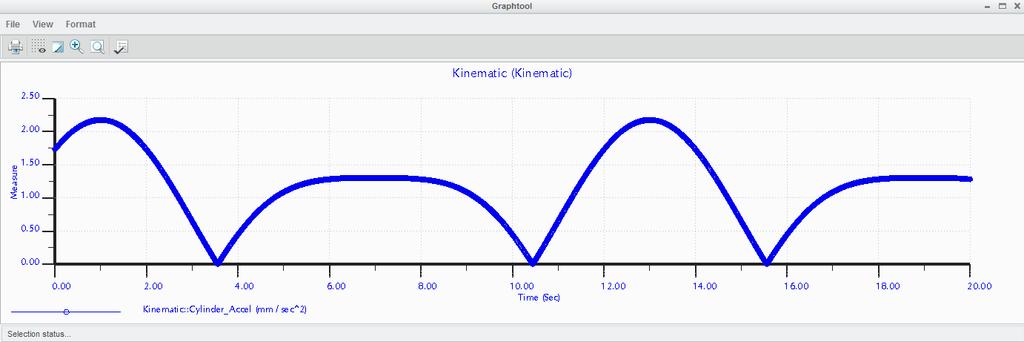
12 - Name your measurement and select its type. A position analysis will display position data. Kinematic analysis will display velocity and acceleration. Finally, dynamic will display all three. - After selecting the type, click the white arrow to select the point or motion axis to measure. An intuitive point to measure would be the Bottom or Top datum points located on the cam follower. The example plots at the end of this manual are from the Bottom datum point. - Once your measurement is created, select it and then select the Result Set that you want to plot from. If the measurement and results are a valid combination, the graph icon at the top of the window will become clickable. Click it to plot your data. Page 12 of 17

13 Task 9 Mechanism Turn In - Run a kinematic analysis on the system using the specified durations provided earlier in the lab manual. Turn in a graph for position, velocity and acceleration for the BOTTOM datum point located on the follower. You should use only the Kinematic result set. - Run a dynamic analysis on the system and turn in a plot of the position of the Bottom datum point of the follower. This analysis should be run with the spring, damper and duration values from earlier in the lab manual. - Run another dynamic analysis on the system, but change the spring constant from.5 to 1. - Your plots do not need to look exactly the same as the plots at the end of this manual. All we are looking for is plots that are similar in shape with roughly the same period, min and max values. Do not worry about matching exactly what is at the end of the lab. - You can use the Snipping Tool to save the plots as.jpg files. The snipping tool is found on every Windows computer in EWS labs. - Export one of your analysis animations to be turned in. o Click on the Playback button located next to the Mechanism Analysis button. Page 13 of 17


14 o Select your Result Set. If it isn t listed in the dropdown click the folder icon and open the result. Results are saved in your working directory. o Click the Play Current Result Set button located to the left of the folder icon to open the playback screen. o Turn the speed to maximum speed and click play to watch your animation. If it is too slow, change the End Time or Frame Rate options and rerun your analysis. o Finally, click capture and click Okay. Creo will start exporting your animation with the default settings. o The video is now located in your working directory. Verify that it works and turn it in. Page 14 of 17

15 Part II. Lab Assignment Turn-In Requirement: 1) Create a zip file named " <netid>_lab10.zip" with the following files. Submit it for grading through the my.mechse website. Be sure to include the latest version of the assembly. Animation.mpg Kinematic_position.jpg Kinematic_vel.jpg Kinematic_accel.jpg Dynamic_position.jpg Dynamic_position_highk.jpg Page 15 of 17


16 Page 16 of 17
17 Part III. Troubleshooting Guide: Here are a few helpful tips to troubleshoot any issues you might encounter. If your dynamic plot doesn t turn out as expected, check if you deleted the servo motor from the motor list. The dynamic plot should only have a force motor listed. Check the units on your spring and damper. They should be in units of m, not mm. Make sure to enter in a new value for your spring and damper constants as just changing the unit will scale the previously input constant. If your animation is not moving make sure to check the units on your spring and damper. The motor may not be able to overcome the spring and damper settings you have setup. If your model isn t animating correctly check to see if your servo motor is set to velocity and not position. Page 17 of 17
Animations in Creo 3.0
 Animations in Creo 3.0 ME170 Part I. Introduction & Outline Animations provide useful demonstrations and analyses of a mechanism's motion. This document will present two ways to create a motion animation
Drawing Tips ME170. Instructor: Mike Philpott (
 Drawing Tips Instructor: Mike Philpott (email: mphilpot@illinois.edu) Configuration of Creo Prepare Creo for drawing creation. - Open Creo Parametric 3.0 from the Start Menu. - Set your working directory.
Lab Assignment #1: Introduction to Creo ME 170
 Lab Assignment #1: Introduction to Creo ME 170 Instructor: Mike Philpott (email: mphilpot@illinois.edu) Date Due: One week from Start Day of Lab (turn in deadline 11pm night before next lab) Make sure
Animation and Mechanization Tutorial
 Animation and Mechanization Tutorial Animation v. Mechanization Animation: Allows the operator to move the standard assembly constraints Distance (Mate, Align and Offset) taking periodic snapshots of the
ME 3222 Design & Manufacturing II. Creating and Animating a Slider-Crank in Creo Elements (Version 2.0)
") ME 3222 Design & Manufacturing II Creating and Animating a Slider-Crank in Creo Elements (Version 2.0) Tom Chase February 18, 2016 Overview This document explains how to create a mechanism and animate
ME 3222 Design & Manufacturing II Creating and Animating a Slider-Crank in Creo Elements (Version 2.0) Tom Chase February 18, 2016 Overview This document explains how to create a mechanism and animate
Creo for Analyst. Overview
 Creo for Analyst Overview In this course, you will learn how to utilize the core functionality enhancements in Creo Parametric 2.0. First, you will become familiar with using and customizing the new ribbon
Introduction To Finite Element Analysis
 Creating a Part In this part of the tutorial we will introduce you to some basic modelling concepts. If you are already familiar with modelling in Pro Engineer you will find this section very easy. Before
Using Flash Animation Basics
 Using Flash Contents Using Flash... 1 Animation Basics... 1 Exercise 1. Creating a Symbol... 2 Exercise 2. Working with Layers... 4 Exercise 3. Using the Timeline... 6 Exercise 4. Previewing an animation...
SolidWorks Motion Study Tutorial
 SolidWorks Motion Study Tutorial By: Mohamed Hakeem Mohamed Nizar Mechanical Engineering Student- May 2015 South Dakota School of Mines & Technology August 2013 Getting Started This tutorial is for you
Mechanism Design using Creo Parametric 3.0
 Mechanism Design using Creo Parametric 3.0 Overview Course Code Course Length TRN-4521-T 1 Day In this course, you will learn about creating mechanism connections, configuring the mechanism model, creating
Step 1: Open the CAD model
 In this exercise you will learn how to: Ground a part Create rigid groups Add joints and an angle motor Add joints and an angle motor Run both transient and statics motion analyses Apply shape controls
Getting Started with HCA and X10
 Getting Started with HCA and X10 This Getting Started Guide continues from the previous Getting Started with HCA Installation and Introduction which covers installing HCA and the basic operations available
CATIA Electrical Space Reservation TABLE OF CONTENTS
 TABLE OF CONTENTS Introduction...1 Manual Format...2 Electrical Reservations...3 Equipment Reservations...5 Pathway Reservations...31 Advanced Reservations...49 Reservation Analysis...67 Clash...69 Sectioning...73
Flow Sim. Chapter 12. F1 Car. A. Enable Flow Simulation. Step 1. If necessary, open your ASSEMBLY file.
 Chapter 12 F1 Car Flow Sim A. Enable Flow Simulation. Step 1. If necessary, open your ASSEMBLY file. Step 2. If necessary, turn on Flow Simulation, click the flyout of Options on the Standard toolbar and
Getting Started with HCA and Insteon
 Getting Started with HCA and Insteon This Getting Started Guide continues from the previous Getting Started with HCA Installation and Introduction which covers installing HCA and the basic operations available
Adobe Flash CS3 Reference Flash CS3 Application Window
 Adobe Flash CS3 Reference Flash CS3 Application Window When you load up Flash CS3 and choose to create a new Flash document, the application window should look something like the screenshot below. Layers
Welcome to MSC.visualNastran 4D. 1.0 Installing MSC.visualNastran 4D
 Welcome to MSC.visualNastran 4D MSC.visualNastran 4D is the result of a twelve-year collaborative effort between professional engineers and software specialists. We are committed to providing you easy-to-use,
Getting Started with HCA and UPB
 Getting Started with HCA and UPB This Getting Started Guide continues from the previous Getting Started with HCA Installation and Introduction which covers installing HCA and the basic operations available
Analysis of a 4 Bar Crank-Rocker Mechanism Using COSMOSMotion
 Analysis of a 4 Bar Crank-Rocker Mechanism Using COSMOSMotion ME345: Modeling and Simulation Professor Frank Fisher Stevens Institute of Technology Last updated: June 29th, 2009 Table of Contents 1. Introduction
Autodesk Inventor 6 Essentials Instructor Guide Chapter Four: Creating Placed Features Chapter Outline This chapter provides instruction on the follow
 Chapter Four: Creating Placed Features Chapter Outline This chapter provides instruction on the following topics and provides exercises for students to practice their skills. Day Two Topic: How to create
Learning the Pro/ENGINEER Interface
 2 Learning the Pro/ENGINEER Interface This chapter introduces the Pro/ENGINEER interface tools: the menus, the dashboards, the selection tools and the viewing controls. As you go through this chapter,
Speedway. Motion Study. Step 2. If necessary, turn on SolidWorks Motion. To turn on SolidWorks Motion, click Tools Menu > Add-Ins.
 Chapter 8 Speedway Motion Study A. Enable SolidWorks Motion. Step 1. If necessary, open your Speedway Assembly file. Step 2. If necessary, turn on SolidWorks Motion. To turn on SolidWorks Motion, click
Lesson 1: Introduction to Pro/MECHANICA Motion
 Lesson 1: Introduction to Pro/MECHANICA Motion 1.1 Overview of the Lesson The purpose of this lesson is to provide you with a brief overview of Pro/MECHANICA Motion, also called Motion in this book. Motion
This page outlines some of the alternate pieces that can be used for building.
 Artbotics Exploring Mechanisms with Lego Mindstorms EV3 This packet contains information on each mechanism you will be using, including a to-scale image of all of the pieces needed to build each one and
Class #10 Wednesday, November 8, 2017
 Graphics In Excel Before we create a simulation, we need to be able to make a drawing in Excel. The techniques we use here are also used in Mathematica and LabVIEW. Drawings in Excel take place inside
Wheels and Axle. Chapter 7. Simples Machines. A. Save As. Step 1. If necessary, open your Track Assembly 15 file. B. Insert Truck Assembly.
 Chapter 7 Simples Machines Wheels and Axle A. Save As. Step 1. If necessary, open your Track Assembly 15 file. Step 2. Click File Menu > Save As. Step 3. Key-in WHEELS AND AXLE ASSEMBLY for the filename
Chapter 19 Assembly Modeling with the TETRIX by Pitsco Building System Autodesk Inventor
 Tools for Design Using AutoCAD and Autodesk Inventor 19-1 Chapter 19 Assembly Modeling with the TETRIX by Pitsco Building System Autodesk Inventor Create and Use Subassemblies in Assemblies Creating an
Overview The egg cup is made by
 123D Design Tutorial: Egg cup using the Loft Tool Before using these instructions, it is very helpful to watch this video screencast of the CAD drawing actually being done in the software. Click this link
Parametric Modeling with. Autodesk Fusion 360. First Edition. Randy H. Shih SDC. Better Textbooks. Lower Prices.
 Parametric Modeling with Autodesk Fusion 360 First Edition Randy H. Shih SDC PUBLICATIONS Better Textbooks. Lower Prices. www.sdcpublications.com Powered by TCPDF (www.tcpdf.org) Visit the following websites
2 SELECTING AND ALIGNING
 2 SELECTING AND ALIGNING Lesson overview In this lesson, you ll learn how to do the following: Differentiate between the various selection tools and employ different selection techniques. Recognize Smart
Introduction to Solid Modeling Using SolidWorks 2008 COSMOSMotion Tutorial Page 1
 Introduction to Solid Modeling Using SolidWorks 2008 COSMOSMotion Tutorial Page 1 In this tutorial, we will learn the basics of performing motion analysis using COSMOSMotion. Although the tutorial can
Visual Physics - Introductory Lab Lab 0
 Your Introductory Lab will guide you through the steps necessary to utilize state-of-the-art technology to acquire and graph data of mechanics experiments. Throughout Visual Physics, you will be using
[Type text] [Type text] [Type text] GearPro Procedure
![[Type text] [Type text] [Type text] GearPro Procedure](/thumbs/77/76062303.jpg "[Type text] [Type text] [Type text] GearPro Procedure") GearPro Procedure Pictured below is the GearPro main screen. In this manual the icons on the top right corner (Chapter 1), far left side (Chapters 2-5), and far right side (Chapters 6&7) will be discussed.
GearPro Procedure Pictured below is the GearPro main screen. In this manual the icons on the top right corner (Chapter 1), far left side (Chapters 2-5), and far right side (Chapters 6&7) will be discussed.
Tangents. In this tutorial we are going to take a look at how tangents can affect an animation.
 Tangents In this tutorial we are going to take a look at how tangents can affect an animation. One of the 12 Principles of Animation is called Slow In and Slow Out. This refers to the spacing of the in
Appendix E: Software
 Appendix E: Software Video Analysis of Motion Analyzing pictures (movies or videos) is a powerful tool for understanding how objects move. Like most forms of data, video is most easily analyzed using a
Create a Customised Tab on the Office 2013 Ribbon
 Create a Customised Tab on the Office 2013 Ribbon Office 2007 saw the addition of the Ribbon feature, which some users found confusing. However, you can use it to your advantage by adding your own custom
Motion Creating Animation with Behaviors
 Motion Creating Animation with Behaviors Part 1: Basic Motion Behaviors Part 2: Stacking Behaviors upart 3: Using Basic Motion Behaviors in 3Do Part 4: Using Simulation Behaviors Part 5: Applying Parameter
Creating a T-Spline using a Reference Image
 1 / 17 Goals Learn how to create a T-Spline using a Reference Image. 1. Insert an image into the workspace using Attach Canvas. 2. Use Calibrate to set the proper scale for the reference image. 3. Invoke
ECSE-323 Digital System Design. Lab #1 Using the Altera Quartus II Software Fall 2008
 1 ECSE-323 Digital System Design Lab #1 Using the Altera Quartus II Software Fall 2008 2 Introduction. In this lab you will learn the basics of the Altera Quartus II FPGA design software through following
Advanced Copy Pro 9.0 Plugin User Guide
 Advanced Copy Pro 9.0 Plugin User Guide UPDATED ON 6/26/2018 PlanSwift Authored by: Dave Hansen 1 Table of Contents Overview... 3 Purchasing and Installation... 4 Purchasing Plugins... 4 Installation and
Recipes4Success. Draw and Animate a Rocket Ship. Frames 5 - Drawing Tools
 Recipes4Success You can use the drawing tools and path animation tools in Frames to create illustrated cartoons. In this Recipe, you will draw and animate a rocket ship. 2012. All Rights Reserved. This
2 Ranking Task: complete this section and submit it to your instructor before you begin the lab.
 Experiment 2 Ranking Task: complete this section and submit it to your instructor before you begin the lab. The position vs. time graph below was made by a moving object. During certain times, the object
ROSE-HULMAN INSTITUTE OF TECHNOLOGY
 Introduction to Working Model Welcome to Working Model! What is Working Model? It's an advanced 2-dimensional motion simulation package with sophisticated editing capabilities. It allows you to build and
Speedway. Motion Study. on the Standard toolbar and click Add-Ins. at the lower
 Chapter 8 Speedway Motion Study A. Enable SOLIDWORKS Motion. Step 1. If necessary, open your Speedway Assembly file. Step 2. If necessary, enable Motion, click the flyout of Options on the Standard toolbar
Creating an Animated Sea Aquarium/Getting Acquainted with Power Point
 Creating an Animated Sea Aquarium/Getting Acquainted with Power Point Directions: Power Point is a presentation graphics application program you use to organize and present information. Whether you are
Flow Sim. Chapter 14 P-51. A. Set Up. B. Create Flow Simulation Project. Step 1. Click Flow Simulation. SolidWorks 10 Flow Sim P-51 Page 14-1
 Chapter 14 A. Set Up. P-51 Flow Sim Step 1. If necessary, open your ASSEMBLY file. Step 2. Click Tools Menu > Add-Ins. Step 3. In the dialog box, scroll down to Flow Simulation and place a check in the
Working with the Dope Sheet Editor to speed up animation and reverse time.
 Bouncing a Ball Page 1 of 2 Tutorial Bouncing a Ball A bouncing ball is a common first project for new animators. This classic example is an excellent tool for explaining basic animation processes in 3ds
Plasticity Bending Machine Tutorial (FFlex)
") Plasticity Bending Machine Tutorial (FFlex) Copyright 2018 FunctionBay, Inc. All rights reserved. User and training documentation from FunctionBay, Inc. is subjected to the copyright laws of the Republic
Plasticity Bending Machine Tutorial (FFlex) Copyright 2018 FunctionBay, Inc. All rights reserved. User and training documentation from FunctionBay, Inc. is subjected to the copyright laws of the Republic
Small rectangles (and sometimes squares like this
 Lab exercise 1: Introduction to LabView LabView is software for the real time acquisition, processing and visualization of measured data. A LabView program is called a Virtual Instrument (VI) because it,
Lesson 17 Shell, Reorder, and Insert Mode
 Lesson 17 Shell, Reorder, and Insert Mode Figure 17.1 Oil Sink OBJECTIVES Master the use of the Shell Tool Reorder features Insert a feature at a specific point in the design order Create a Hole Pattern
Computer Essentials Session 1 Lesson Plan
 Note: Completing the Mouse Tutorial and Mousercise exercise which are available on the Class Resources webpage constitutes the first part of this lesson. ABOUT PROGRAMS AND OPERATING SYSTEMS Any time a
REMEMBER TO BRING YOUR MEMORY STICK TO EVERY LAB!
 CS 1033 Multimedia and Communications Lab 07: Introduction to Animation using Photoshop REMEMBER TO BRING YOUR MEMORY STICK TO EVERY LAB! LAB #7 - Exercise 1 Objectives: Upon completion of Exercise 1 you
Candy is Dandy Project (Project #12)
") Candy is Dandy Project (Project #12) You have been hired to conduct some market research about M&M's. First, you had your team purchase 4 large bags and the results are given for the contents of those
Candy is Dandy Project (Project #12) You have been hired to conduct some market research about M&M's. First, you had your team purchase 4 large bags and the results are given for the contents of those
KIN 147 Lab Practical Mid-term: Tibial Acceleration Data Analysis Excel analyses work much better on PCs than on Macs (especially older Macs)
") KIN 147 Lab Practical Mid-term: Tibial Acceleration Data Analysis Excel analyses work much better on PCs than on Macs (especially older Macs) Your goal is to correctly analyze accelerometer data Analyzing
KIN 147 Lab Practical Mid-term: Tibial Acceleration Data Analysis Excel analyses work much better on PCs than on Macs (especially older Macs) Your goal is to correctly analyze accelerometer data Analyzing
Introduction to PowerPoint 2007
 Introduction to PowerPoint 2007 PowerPoint is one of the programs included in the Microsoft Office suite. It s used to create presentations, also called slide shows, that are typically displayed via a
Engine with Propeller Tutorial (Professional)
") Engine with Propeller Tutorial (Professional) Copyright 2017 FunctionBay, Inc. All rights reserved. User and training documentation from FunctionBay, Inc. is subjected to the copyright laws of the Republic
Engine with Propeller Tutorial (Professional) Copyright 2017 FunctionBay, Inc. All rights reserved. User and training documentation from FunctionBay, Inc. is subjected to the copyright laws of the Republic
User Interface Guide
 User Interface Guide 1 Contents Overview... 3 Tabmenu... 4 Design modes... 4 Tool groups... 5 Design function groups... 5 Main menu... 6 Toolbars... 7 Drawing area... 9 Status bar... 11 Coordinate box...
Excel 2013 Intermediate
 Instructor s Excel 2013 Tutorial 2 - Charts Excel 2013 Intermediate 103-124 Unit 2 - Charts Quick Links Chart Concepts Page EX197 EX199 EX200 Selecting Source Data Pages EX198 EX234 EX237 Creating a Chart
ME Week 12 Piston Mechanical Event Simulation
 Introduction to Mechanical Event Simulation The purpose of this introduction to Mechanical Event Simulation (MES) project is to explorer the dynamic simulation environment of Autodesk Simulation. This
Exercise 4a: Creating and Editing XY Plots
 Exercise 4a: Creating and Editing XY Plots This exercise uses the data file, LINACC. Step 1: Load the file LINACC and create multiple plots. 1. Open HyperWorks Desktop and set the application to HyperGraph
ME scope Application Note 17 Order Tracked Operational Deflection Shapes using VSI Rotate & ME scope
 ME scope Application Note 17 Order Tracked Operational Deflection Shapes using VSI Rotate & ME scope Requirements This application note requires the following software, Vold Solutions VSI Rotate Version
CHAPTER 1 COPYRIGHTED MATERIAL. Finding Your Way in the Inventor Interface
 CHAPTER 1 Finding Your Way in the Inventor Interface COPYRIGHTED MATERIAL Understanding Inventor s interface behavior Opening existing files Creating new files Modifying the look and feel of Inventor Managing
SolidWorks 2½D Parts
 SolidWorks 2½D Parts IDeATe Laser Micro Part 1b Dave Touretzky and Susan Finger 1. Create a new part In this lab, you ll create a CAD model of the 2 ½ D key fob below to make on the laser cutter. Select
Use Parametric notation. Interpret the effect that T has on the graph as motion.
 Learning Objectives Parametric Functions Lesson 3: Go Speed Racer! Level: Algebra 2 Time required: 90 minutes One of the main ideas of the previous lesson is that the control variable t does not appear
USING THE TRIBALL FOR POSITIONING
 USING THE TRIBALL FOR POSITIONING Although many important positioning tools are available, none are as versatile as the TriBall tool. This TriBall tool offers complete repositioning of many items: Shapes
This tutorial will take you all the steps required to import files into ABAQUS from SolidWorks
 ENGN 1750: Advanced Mechanics of Solids ABAQUS CAD INTERFACE TUTORIAL School of Engineering Brown University This tutorial will take you all the steps required to import files into ABAQUS from SolidWorks
-Remember to always hit Command + S every time you make a change to your project going forward.
 -Open Animate -Under Create New - Select ActionScript 3.0 -Choose Classic as the Design type located in the upper right corner -Animate workspace shows a toolbar, timeline, stage, and window tabs -From
Lesson 14 Blends. For Resources go to > click on the Creo Parametric 2.0 Book cover
 Lesson 14 Blends Figure 14.1 Cap OBJECTIVES Create a Parallel Blend feature Use the Shell Tool Create a Hole Pattern REFERENCES AND RESOURCES For Resources go to www.cad-resources.com > click on the Creo
Simulation of Turbulent Flow around an Airfoil
 1. Purpose Simulation of Turbulent Flow around an Airfoil ENGR:2510 Mechanics of Fluids and Transfer Processes CFD Lab 2 (ANSYS 17.1; Last Updated: Nov. 7, 2016) By Timur Dogan, Michael Conger, Andrew
Physics 211 E&M and Modern Physics Spring Lab #1 (to be done at home) Plotting with Excel. Good laboratory practices
 Plotting with Excel. Good laboratory practices") NORTHERN ILLINOIS UNIVERSITY PHYSICS DEPARTMENT Physics 211 E&M and Modern Physics Spring 2018 Lab #1 (to be done at home) Lab Writeup Due: Mon/Wed/Thu/Fri, Jan. 22/24/25/26, 2018 Read Serway & Vuille:
NORTHERN ILLINOIS UNIVERSITY PHYSICS DEPARTMENT Physics 211 E&M and Modern Physics Spring 2018 Lab #1 (to be done at home) Lab Writeup Due: Mon/Wed/Thu/Fri, Jan. 22/24/25/26, 2018 Read Serway & Vuille:
Lesson: Static Stress Analysis of a Connecting Rod Assembly
 Lesson: Static Stress Analysis of a Connecting Rod Assembly In this tutorial we determine the effects of a 2,000 pound tensile load acting on a connecting rod assembly (consisting of the rod and two pins).
SolidWorks Intro Part 1b
 SolidWorks Intro Part 1b Dave Touretzky and Susan Finger 1. Create a new part We ll create a CAD model of the 2 ½ D key fob below to make on the laser cutter. Select File New Templates IPSpart If the SolidWorks
2. Click on the Launch button and select Terminal. A window will appear which looks like:
 1. Log-in to one of the lab computers. If given a choice, select Gnome/Java Desktop (JDS) as your window manager. Don't select the Common Desktop Environment (CDE). You should then see something like the
Part A: Monitoring the Rotational Sensors of the Motor
 LEGO MINDSTORMS NXT Lab 1 This lab session is an introduction to the use of motors and rotational sensors for the Lego Mindstorm NXT. The first few parts of this exercise will introduce the use of the
4 TRANSFORMING OBJECTS
 4 TRANSFORMING OBJECTS Lesson overview In this lesson, you ll learn how to do the following: Add, edit, rename, and reorder artboards in an existing document. Navigate artboards. Select individual objects,
Design and Print Instruction Manual
 Diamond Design Design and Print Instruction Manual Contents Installation 1 Installing the Diamond Design Software 2-3 Installing the ORIGINAL Argox OS-214 printer drivers 4 Installing the EXCEL Argox OS-314
To complete this project, you will need the following folder:
 = CHAPTER 1 Windows 7 More Skills 12 Use Libraries to Organize Files A library is a collection of files and folders stored in different locations on your computer that can be viewed as a single folder.
Review the interactive to learn how to navigate and interact with slides in the PowerPoint window.
 Getting Started with PowerPoint Introduction Page 1 PowerPoint 2010 is a presentation software that allows you to create dynamic slide presentations that may include animation, narration, images, videos
liquivid Video Improve v2.x Installation Instructions for Windows, macos, Adobe Lightroom Manual
 liquivid Video Improve v2.x Installation Instructions for Windows, macos, Adobe Lightroom Manual Installation Instructions for Windows... 3 Required Hardware & Software... 3 Installation... 3 File Saving
Exchange Address Book Order
 Exchange Address Book Order From your Outlook Ribbon, locate the Address Book Click on Tools, Options 3 options are available, as shown below, select Custom to arrange the order of your address books.
KIN 147 Lab 02: Acceleration Data Analysis
 KIN 147 Lab 02: Acceleration Data Analysis Excel analyses work much better on PCs than on Macs (especially older Macs) Your goal is to correctly analyze accelerometer data Analyzing the Acceleration Data
An Introduction to Motion Analysis Applications with SolidWorks Motion, Instructor Guide
 Engineering Design and Technology Series An Introduction to Motion Analysis Applications with SolidWorks Motion, Instructor Guide Dassault Systèmes SolidWorks Corporation 300 Baker Avenue Concord, Massachusetts
Text Box Frames. Format Text Box
 Text Box Frames Publisher is different from Word Processing software in that text in Publisher only exists in Text Box Frames. These frames make it possible to type or import text and then move or resize
What s New to Version 3.0
 SU Animate 3.0 Guide What s New to Version 3.0... 2 Install... 3 Cameras, Curves & Paths... 4 Use a Camera path to create a simple walk thru effect... 6 Animating Objects with Target Groups... 6 Using
Electrical Starter Pack User Guide
 Electrical Starter Pack User Guide UPDATED ON 11/21/2018 PlanSwift Authored by: Dave Hansen 1 Table of Contents Overview... 3 Purchasing and Installation... 4 Purchasing Plugins... 4 Installation and Uninstallation...
The previous tutorial introduced you to 3D mesh objects. In this tutorial, you learn how to smooth them.
 New Commands in AutoCAD 2010: Part 11 Smoothing 3D Mesh Objects by Ralph Grabowski Introduction The previous tutorial introduced you to 3D mesh objects. In this tutorial, you learn how to smooth them.
Introduction to Engineering Analysis
 Chapter 1 Introduction to Engineering Analysis This chapter introduces you to the Stress Analysis and Dynamic Simulation environments. You learn how digital prototyping can be used to simulate your designs
Lesson 14 Blends. For Resources go to > click on the Creo Parametric Book cover
 Lesson 14 Blends Figure 14.1 Cap OBJECTIVES Create a Parallel Blend feature Use the Shell Tool Create a Swept Blend REFERENCES AND RESOURCES For Resources go to www.cad-resources.com > click on the Creo
Setup Instructions DOF Reality M2
 During initial assembly don t tight bolts completely, do it at the end. First you need to assemble full frame and fight screws and bolts after. The following arrow highlights the spot on the diagram or
3 AXIS STANDARD CAD. BobCAD-CAM Version 28 Training Workbook 3 Axis Standard CAD
 3 AXIS STANDARD CAD This tutorial explains how to create the CAD model for the Mill 3 Axis Standard demonstration file. The design process includes using the Shape Library and other wireframe functions
Autodesk Inventor - Basics Tutorial Exercise 1
 Autodesk Inventor - Basics Tutorial Exercise 1 Launch Inventor Professional 2015 1. Start a New part. Depending on how Inventor was installed, using this icon may get you an Inch or Metric file. To be
Chapter 18 Assembly Modeling with the LEGO MINDSTORMS NXT Set Autodesk Inventor
 Tools for Design Using AutoCAD and Autodesk Inventor 18-1 Chapter 18 Assembly Modeling with the LEGO MINDSTORMS NXT Set Autodesk Inventor Creating an Assembly Using Parts from the LEGO MINDSTORMS NXT Set
How to work with temporal and spatial keyframe interpolation
 How to work with temporal and spatial keyframe interpolation Keyframe interpolation changes the behavior of an effect option value as the clip plays toward or away from a keyframe. The two most common
Microsoft PowerPoint 2016 Part 2: Notes, Links, & Graphics. Choosing a Design. Format Background
 Microsoft PowerPoint 2016 Part 2: Notes, Links, & Graphics Choosing a Design Open PowerPoint. Click on Blank Presentation. Click on the Design tab. Click on the design tab of your choice. In part one we
Spur Gears Static Stress Analysis with Linear Material Models
 Exercise A Spur Gears Static Stress Analysis with Linear Material Models Beam and Brick Elements Objective: Geometry: Determine the stress distribution in the spur gears when a moment of 93.75 in-lb is
PowerPoint 2013 Advanced. PowerPoint 2013 Advanced SAMPLE
 PowerPoint 2013 Advanced PowerPoint 2013 Advanced PowerPoint 2013 Advanced Page 2 2013 Cheltenham Courseware Pty. Ltd. All trademarks acknowledged. E&OE. No part of this document may be copied without
The Monitor Window. 3.The Monitor Window Premiere Pro 1.5 H O T
 3.The Monitor Window Premiere Pro 1.5 H O T 3 The Monitor Window Source vs. Program Playing Source Video In and Out Points Setting In and Out Points Clearing In and Out Points H O T Premiere Pro HOT DVD
PowerPoint 2016 Part II
 PowerPoint 2016 Part II Animations In PowerPoint, any object, shape, image, etc. on a slide can be animated. Animations are a good way to add some attention grabbers to a presentation, but they can also
KCS Motion. Video Motion Analysis Software
 Video Motion Analysis Software Software and supporting material is property of G. Mason, Seattle University, 2007 Overview Overview KCS Motion tracks moving objects in a video clip and analyzes their position,
Creating a Text Frame. Create a Table and Type Text. Pointer Tool Text Tool Table Tool Word Art Tool
 Pointer Tool Text Tool Table Tool Word Art Tool Picture Tool Clipart Tool Creating a Text Frame Select the Text Tool with the Pointer Tool. Position the mouse pointer where you want one corner of the text