User Interface Guide
|
|
|
- Ethelbert Small
- 5 years ago
- Views:
Transcription
1 User Interface Guide 1
2 Contents Overview... 3 Tabmenu... 4 Design modes... 4 Tool groups... 5 Design function groups... 5 Main menu... 6 Toolbars... 7 Drawing area... 9 Status bar Coordinate box Layer button Special point editors Object snap tools Command line Filter Tool palettes Dialogs Chain button Numeric edit boxes List boxes Key bindings

3 Overview 3
4 Tabmenu This toolbar contains the main functionalities. The order of the tabs follows the suggested workflow of design. Each tab has different layer mode. By default, the status of the layers (Hidden, Protected, Active) is different for each tab according to the function of the particular tab, so that you cannot, for example, delete or alter a structural element accidentally while working with loads. The status of any layer can also be adjusted manually, however (Status bar/current layer). Design modes The buttons on the right side of the tabmenu represent various design modes. When in a particular design mode, the set of tabs in the tabmenu might change to reflect the functionalities available to that particular design mode. Documentation - In this mode, multi-page documentation of your project can be defined manually or by applying templates. New templates can also be created. Documentation can contain figures of structure, loads and results, chapters, texts, tables, images and title blocks (headers and footers). Exit current mode - Pressing this button, you can return to the previous design mode. 4
5 Tool groups Tools are organized into groups on the tabmenu. To spare space on the screen, most of them can be compacted into a single button, by clicking on the grey triangle at the lower left corner of the group. By clicking the grey triangle again the group can be reexpanded. Expanded group - an expanded tool group behaves just like and ordinary group, having a separate icon for each item of the group. Compacted group - a collapsed group is represented by a single icon on the tabmenu. Clicking the icon, it works like a simple push button. Hovering the mouse over the bottom right corner of the button (over the black triangle), a dropmenu appears, where you can select another tool from the group. Design function groups While designing reinforced concrete, steel or timber structures, a design function group is displayed on the tabmenu. It allows the user to select a particular structure or feature to design, as well as providing access to functionalities available to that structure only. You can switch function by clicking the leftmost icon of the group and select an item from the dropdown menu. Please note that, unlike that of a tool group, the icon of a design function group does not behave like a push button, it merely shows the current design mode. 5
 can be placed as a button on one of the toolbars, that can be placed around the Drawing area. Some commands can be executed by hotkeys.")
6 Main menu The Main menu contains file operations, drawing and editing commands, assistance tools, settings, views, window-system and user-guides (Help). Each menu item (a command along with the corresponding icon) can be placed as a button on one of the toolbars, that can be placed around the Drawing area. Some commands can be executed by hotkeys. The hotkey (or combination) for a particular command can be found on the right side of the dropdown menu along with the associated item. 6


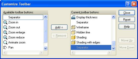
7 Toolbars The command icons of Main menu can be grouped into toolbars and placed around the Drawing area. By default, only the Standard and View toolbars are shown, the others remain hidden. You can drag a toolbar and move it around by clicking the left mouse button over the left edge of the toolbar and holding the button pressed. You can stick the toolbar to any of the four edges of the drawing area. If you right-click anywhere on the menu or on one of the additional toolbars, you can choose which toolbars are to be shown or hidden from the popup menu. By selecting the "Customize..." menu item, you may add or remove icons from the current toolbar (which was clicked upon). 7
8 8
 respectively. Its origin and directions can be modified at \"View/UCS\".")
9 Drawing area The thin arrows show the axes of the Global (or World) Coordinate System (WCS). The position of the origin and directions are fixed. The green and red infinite lines show the x' and y' axes of the user coordinate system (UCS) respectively. Its origin and directions can be modified at "View/UCS". If the origin of the UCS is out of the current view, the two thick arrows remains in view at the bottom of the drawing area giving the user a hint about the directions of the UCS. The location of the two arrows on the drawing area depends on your setting on "Settings/All/Window/Coordinate systems". 9
10 A list of currently available windows are shown at the bottom of the drawing area. In this case you can choose a window simply by clicking on its name. You may change the window's name of a window by right-clicking on its tab. Default mouse button actions available in the drawing area: Right button "Edit" menu Wheel up Zoom In Wheel down Zoom Out Middle button Animate pan Ctrl + Middle button Animate rotate around the center of the model cube Alt + Middle button Animate rotate around the user defined point Middle button double click Zoom margin There are quite a few ways to select objects: "Right to Left sweep" box selection Selects everything that the selection box intersects or covers. "Left to Right sweep" box selection Selects everything that is completely inside the box. Right button Selects the object that the cursor is hovering over. Shift + Right button Selects the object that the cursor is hovering over plus all the other objects of the same type. Ctrl + selection When holding "Ctrl" key pressed while selecting the first object by any of the methods above, the program lets you continue selection until "Enter" is pressed. Ctrl + A Selects all the objects the current command is applicable to. Quick modifications are implemented for all elements, depending on where the cursor is standing: Click LB (default) Click + hold LB CTRL + hold LB Line's end point Stretch Stretch Drag a copy Node on surface edge Along point along line Curve Move Drag a copy Any point inside surface Move Move Drag a copy Any point on screen, Box selection where there is nothing By right mouse clicking user can select another command in the Modify menu, whick is also available by right mouse clicking. 10
11 Status bar Coordinate box Shows the exact coordinates of the crosshair cursor. If you click on the box, while you are in any drawing and definition tools, you can define an exact coordinate of the point. The coordinate can be valid in WCS or UCS By clicking this button, you may change the orthogonal coordinate system to parametric coordinate system. Layer button By clicking on this button you may access the layer manager of the application, where you can set the status and properties of all the layers. Special point editors This option will provide reference line and point by using existing line and point during drawing and editing. Object snap tools Here you can set the snapping distance and turn object snaps on and off. Command line Here you can directly communicate with the program (eg.: typing in coordinate values). This field displays additional messages to show the steps of the current command. 11
12 In the command line you can define coordinates in several way: or 10,30,20 Using absolute coordinates in Descartes coordinate system: X=10, Y=30, Z=20. If only 2 coordinates are defined then Z=0. P Using polar coordinates: point is positioned with an angle of 45 degrees and 5 units from the X-axis and 10 units from the XY plane. R Using relative coordinates: point is positioned X=2.5, Y=3.5, Z=4.5 units from the last entered point. If only 2 coordinates are defined then Z=0. The coordinates are always valid in UCS. Add decimal point by "." (dot instead of comma). 12

13 Filter The new feature Filter is a pop-up window in the workspace, which helps to select the requested objects easily for all kind of editing and modifying functions. When clicking on it, the following appears: With the cursor pointing on Point support group +,- and & buttons appear, enabling the user to add or remove different elements. If you want to select most, but not all of the point support groups, you should click +, and then Continue for cancelling the few individual supports not needed for the selection. The & button works as an AND boolean operator: If you want to select the columns on the second storey, you have to click + at column and then & at storey 2. After closing the Filter palette, it can be switched on again by a right click on any toolbar, or on the main menu zone. Another way is available through Settings>All>Environment>General>View where filter palette can switched on and off: 13
.")
14 Tool palettes In most cases a command has its own "Tool palette", containing all the neccessary definitions and settings related to that particular command. The parts of a tool palette: Toolbar This toolbar is used to change editing mode. Main editing modes are: Define Properties Creates new objects with current settings (Default settings). Ask and/or changes the properties of selected object/s. "Default settings" button If this button is enabled, then you can set all default parameters for the given object type. Otherwise it only shows the symbol of the function. 14
15 Object parameters Here you can set the frequently changed parameters of the object while defining it. 15

.")
16 Dialogs Chain button If there is a "Chain" button next to an edit box and is pressed, any changes made to the related edit box will be transferred to the next edit box automatically. At the second example, if you set t1's value to ' ' then t2 and t3 will also be set to ' '. Numeric edit boxes If you press "c" button on the keyboard while a numeric field has the focus, then the Windows Calculator pops up. It is automatically filled in with the content of the edit box. When you close the Calculator, the value calculated or typed in would be written into the numeric field. It can be used with both views of the Calculator (Normal and Scientific). List boxes In some cases if you double-click on a list box item, then - apart from selecting the given item - the program performs an additional function. E.g.: when selecting an item in "Select result" dialog with a double-click, the program also calls the "Display and exit" command of the dialog. 16
17 Key bindings The following buttons have special functionalities during editing:... Temporarily activate object snap functions. Defines point on a line or edge by giving distance from the closest end point. Inserts a point relative from the position of the crosshair. Moves UCS to cursor position. + Moves UCS back to WCS (restores its original state). Cancels pending command. Opens the properties dialog ("Default settings") of the current command. Confirms data input / repeats last command / finishes multi-selection. Restarts the steps of the current command. Goes back to previous step in a multi-step command. Besides these, most of the commands can be accessed by hotkeys (see Main menu). 17
SolidWorks Intro Part 1b
 SolidWorks Intro Part 1b Dave Touretzky and Susan Finger 1. Create a new part We ll create a CAD model of the 2 ½ D key fob below to make on the laser cutter. Select File New Templates IPSpart If the SolidWorks
SolidWorks 2½D Parts
 SolidWorks 2½D Parts IDeATe Laser Micro Part 1b Dave Touretzky and Susan Finger 1. Create a new part In this lab, you ll create a CAD model of the 2 ½ D key fob below to make on the laser cutter. Select
The Department of Construction Management and Civil Engineering Technology CMCE-1110 Construction Drawings 1 Lecture Introduction to AutoCAD What is
 The Department of Construction Management and Civil Engineering Technology CMCE-1110 Construction Drawings 1 Lecture Introduction to AutoCAD What is AutoCAD? The term CAD (Computer Aided Design /Drafting)
Parametric Modeling with. Autodesk Fusion 360. First Edition. Randy H. Shih SDC. Better Textbooks. Lower Prices.
 Parametric Modeling with Autodesk Fusion 360 First Edition Randy H. Shih SDC PUBLICATIONS Better Textbooks. Lower Prices. www.sdcpublications.com Powered by TCPDF (www.tcpdf.org) Visit the following websites
General Information Project management Introduction... 4 Getting Started Input geometry... 7
 Tutorial Shell Tutorial Shell All information in this document is subject to modification without prior notice. No part or this manual may be reproduced, stored in a database or retrieval system or published,
This lesson introduces Blender, covering the tools and concepts necessary to set up a minimal scene in virtual 3D space.
 3D Modeling with Blender: 01. Blender Basics Overview This lesson introduces Blender, covering the tools and concepts necessary to set up a minimal scene in virtual 3D space. Concepts Covered Blender s
Using TeraRecon intuition Viewer with STAT Quick Reference Guide
 Using TeraRecon intuition Viewer with STAT Quick Reference Guide 1. Launching intuition 2. 3D Assessment of Coronary Arteries for Stenosis 3. Time Volume Analysis (TVA) for Determination of Left Ventricular
solidthinking Environment...1 Modeling Views...5 Console...13 Selecting Objects...15 Working Modes...19 World Browser...25 Construction Tree...
 Copyright 1993-2009 solidthinking, Inc. All rights reserved. solidthinking and renderthinking are trademarks of solidthinking, Inc. All other trademarks or service marks are the property of their respective
Text Box Frames. Format Text Box
 Text Box Frames Publisher is different from Word Processing software in that text in Publisher only exists in Text Box Frames. These frames make it possible to type or import text and then move or resize
Press the Plus + key to zoom in. Press the Minus - key to zoom out. Scroll the mouse wheel away from you to zoom in; towards you to zoom out.
 Navigate Around the Map Interactive maps provide many choices for displaying information, searching for more details, and moving around the map. Most navigation uses the mouse, but at times you may also
2D Tutorial. Project Description: Running VisualAnalysis: Setting Up the Project:
 2D Tutorial Project Description: This project has been set-up to demonstrate the basic features of VisualAnalysis. You will model and analyze the following two-dimensional frame with a curved glue-laminated
Chapter 2 Parametric Modeling Fundamentals
 2-1 Chapter 2 Parametric Modeling Fundamentals Create Simple Extruded Solid Models Understand the Basic Parametric Modeling Procedure Create 2-D Sketches Understand the "Shape before Size" Approach Use
Basic Modeling 1 Tekla Structures 12.0 Basic Training September 19, 2006
 Tekla Structures 12.0 Basic Training September 19, 2006 Copyright 2006 Tekla Corporation Contents Contents 3 1 5 1.1 Start Tekla Structures 6 1.2 Create a New Model BasicModel1 7 1.3 Create Grids 10 1.4
Introduction to SolidWorks Basics Materials Tech. Wood
 Introduction to SolidWorks Basics Materials Tech. Wood Table of Contents Table of Contents... 1 Book End... 2 Introduction... 2 Learning Intentions... 2 Modelling the Base... 3 Modelling the Front... 10
Control the Workplane
 Control the Workplane This tutorial outlines the procedures to understand and control the user coordinate system (UCS). You can realign and reorient the UCS to create and modify 3D objects on 2D workplanes
Advance Design. Tutorial
 TUTORIAL 2018 Advance Design Tutorial Table of Contents About this tutorial... 1 How to use this guide... 3 Lesson 1: Preparing and organizing your model... 4 Step 1: Start Advance Design... 5 Step 2:
Capstone Appendix. A guide to your lab computer software
 Capstone Appendix A guide to your lab computer software Important Notes Many of the Images will look slightly different from what you will see in lab. This is because each lab setup is different and so
Tutorial 3: Constructive Editing (2D-CAD)
") (2D-CAD) The editing done up to now is not much different from the normal drawing board techniques. This section deals with commands to copy items we have already drawn, to move them and to make multiple
(2D-CAD) The editing done up to now is not much different from the normal drawing board techniques. This section deals with commands to copy items we have already drawn, to move them and to make multiple
OpenForms360 Validation User Guide Notable Solutions Inc.
 OpenForms360 Validation User Guide 2011 Notable Solutions Inc. 1 T A B L E O F C O N T EN T S Introduction...5 What is OpenForms360 Validation?... 5 Using OpenForms360 Validation... 5 Features at a glance...
Autodesk Inventor - Basics Tutorial Exercise 1
 Autodesk Inventor - Basics Tutorial Exercise 1 Launch Inventor Professional 2015 1. Start a New part. Depending on how Inventor was installed, using this icon may get you an Inch or Metric file. To be
Troubleshooting in Microsoft Excel 2002
 Page 1 of 8 Troubleshooting in Microsoft Excel 2002 Result: To understand how to work with the Excel software to enter data, navigate the page, and print materials. Tabs Look at the tabs at the bottom
Virtual MODELA USER'S MANUAL
 Virtual MODELA USER'S MANUAL Virtual MODELA is a program that simulates the movement of the tool on the screen. Contents Contents Part 1 Introduction 1-1 System Requirements... 4 1-2 Overview of Virtual
Getting Started. In This Chapter
 Getting Started In This Chapter 2 This chapter introduces concepts and procedures that help you get started with AutoCAD. You learn how to open, close, and manage your drawings. You also learn about the
Tetra4D Reviewer. Version 5.1. User Guide. Details on how to use Tetra4D Reviewer.
 Tetra4D Reviewer Version 5.1 User Guide Details on how to use Tetra4D Reviewer. ii Contents Chapter 1: Work area... 7 Looking at the work area... 7 Toolbars and toolbar presets... 8 About toolbars and
Flair Geometry Editor Part I. Beginners FLUKA Course
 Flair Geometry Editor Part I Beginners FLUKA Course Starting the Geometry Editor Click on icon or from Menu View Geometry Editor or with [F4] shortcut Either start flair with option -g 2 Geometry editor
Beginning Paint 3D A Step by Step Tutorial. By Len Nasman
 A Step by Step Tutorial By Len Nasman Table of Contents Introduction... 3 The Paint 3D User Interface...4 Creating 2D Shapes...5 Drawing Lines with Paint 3D...6 Straight Lines...6 Multi-Point Curves...6
SOLIDWORKS: Lesson 1 - Basics and Modeling. Introduction to Robotics
 SOLIDWORKS: Lesson 1 - Basics and Modeling Fundamentals Introduction to Robotics SolidWorks SolidWorks is a 3D solid modeling package which allows users to develop full solid models in a simulated environment
LAB # 2 3D Modeling, Properties Commands & Attributes
 COMSATS Institute of Information Technology Electrical Engineering Department (Islamabad Campus) LAB # 2 3D Modeling, Properties Commands & Attributes Designed by Syed Muzahir Abbas 1 1. Overview of the
LIGHTCONVERSE TOOLS Interface Overview
 MANUAL 1 Contents Contents... 1 LIGHTCONVERSE TOOLS Interface Overview... 2 Tool Manager... 3 Mouse... 4 Mouse Control Operation:... 4 3D Space Area... 4 Modes... 5 Balance Calculator in Warehouse Mode...
Photocopiable/digital resources may only be copied by the purchasing institution on a single site and for their own use ZigZag Education, 2013
 SketchUp Level of Difficulty Time Approximately 15 20 minutes Photocopiable/digital resources may only be copied by the purchasing institution on a single site and for their own use ZigZag Education, 2013
SOLIDWORKS 2017 Keyboard Modifiers & Shortcuts
 SOLIDWORKS 2017 Keyboard Modifiers & Shortcuts Copy/Paste Ctrl+C and Ctrl+V These are similar in functionality to Windows. Sketches Copies and pastes sketch entities. Part Copies and pastes sketches. Assemblies
Blender Notes. Introduction to Digital Modelling and Animation in Design Blender Tutorial - week 1 The Blender Interface and Basic Shapes
 Blender Notes Introduction to Digital Modelling and Animation in Design Blender Tutorial - week 1 The Blender Interface and Basic Shapes Introduction Blender is a powerful modeling, animation and rendering
TUTORIAL 01: RHINO INTERFACE. By Jeremy L Roh, Professor of Digital Methods I UNC Charlotte s School of Architecture
 TUTORIAL 01: RHINO INTERFACE By Jeremy L Roh, Professor of Digital Methods I UNC Charlotte s School of Architecture Upon opening Rhinoceros 4.0, a Startup Template Dialog Box will appear. Left-click on
Schematic Editing Essentials
 Summary Application Note AP0109 (v2.0) March 24, 2005 This application note looks at the placement and editing of schematic objects in Altium Designer. This application note provides a general overview
Maple Quick Start. Maplesoft, a division of Waterloo Maple Inc.
 Maple Quick Start Maplesoft, a division of Waterloo Maple Inc. This tutorial is designed to help you become familiar with the Maple environment and teach you the few fundamental concepts and tools you
Autodesk Inventor Design Exercise 2: F1 Team Challenge Car Developed by Tim Varner Synergis Technologies
 Autodesk Inventor Design Exercise 2: F1 Team Challenge Car Developed by Tim Varner Synergis Technologies Tim Varner - 2004 The Inventor User Interface Command Panel Lists the commands that are currently
Chapter 4. Part 1 AutoCAD Basics
 Chapter 4. Part 1 AutoCAD Basics Chapter Objectives Describe the AutoCAD screen layout. Perform an AutoCAD drawing setup, including setting units, limits, layers, linetypes, and lineweights. Explain the
Tools for Design. Using AutoCAD 2015 and Autodesk Inventor 2015 SDC. Hand Sketching, 2D Drawing and 3D Modeling. Randy H. Shih
 Tools for Design Using AutoCAD 2015 and Autodesk Inventor 2015 Hand Sketching, 2D Drawing and 3D Modeling Randy H. Shih SDC PUBLICATIONS Better Textbooks. Lower Prices. www.sdcpublications.com Powered
Parametric Modeling with UGS NX 4
 Parametric Modeling with UGS NX 4 Randy H. Shih Oregon Institute of Technology SDC PUBLICATIONS Schroff Development Corporation www.schroff.com www.schroff-europe.com 2-1 Chapter 2 Parametric Modeling
Apex Sketch v7. Define First
 Apex Sketch v7 Legacy Draw First Drawing Method Define First Apex Sketch Version 7 Define First Apex Sketch Version 7 uses the same keystrokes as you would use traditionally in any other Apex program.
Guide to WB Annotations
 Guide to WB Annotations 04 May 2016 Annotations are a powerful new feature added to Workbench v1.2.0 (Released May 2016) for placing text and symbols within wb_view tabs and windows. They enable generation
CHAPTER 1 COPYRIGHTED MATERIAL. Getting to Know AutoCAD. Opening a new drawing. Getting familiar with the AutoCAD and AutoCAD LT Graphics windows
 CHAPTER 1 Getting to Know AutoCAD Opening a new drawing Getting familiar with the AutoCAD and AutoCAD LT Graphics windows Modifying the display Displaying and arranging toolbars COPYRIGHTED MATERIAL 2
Lesson 1: Creating T- Spline Forms. In Samples section of your Data Panel, browse to: Fusion 101 Training > 03 Sculpt > 03_Sculpting_Introduction.
 3.1: Sculpting Sculpting in Fusion 360 allows for the intuitive freeform creation of organic solid bodies and surfaces by leveraging the T- Splines technology. In the Sculpt Workspace, you can rapidly
INTRODUCTION TO CHEMDRAW ULTRA 12.0
 INTRODUCTION TO CHEMDRAW ULTRA 12.0 ITEC107 - Introduction to Computing for Pharmacy 1 Objectives Why use ChemDraw Open, view, save and close a document Exploring the user-interface and toolbars Analyzing
3 AXIS STANDARD CAD. BobCAD-CAM Version 28 Training Workbook 3 Axis Standard CAD
 3 AXIS STANDARD CAD This tutorial explains how to create the CAD model for the Mill 3 Axis Standard demonstration file. The design process includes using the Shape Library and other wireframe functions
Parametric Modeling with NX 12
 Parametric Modeling with NX 12 NEW Contains a new chapter on 3D printing Randy H. Shih SDC PUBLICATIONS Better Textbooks. Lower Prices. www.sdcpublications.com Powered by TCPDF (www.tcpdf.org) Visit the
Impress Guide Chapter 11 Setting Up and Customizing Impress
 Impress Guide Chapter 11 Setting Up and Customizing Impress This PDF is designed to be read onscreen, two pages at a time. If you want to print a copy, your PDF viewer should have an option for printing
Digital City: Introduction to 3D modeling
 Digital City: Introduction to 3D modeling Weixuan Li, 2017 PART I: Install SketchUp and Introduction 1. Download SketchUp Download SketchUp from their official website: https://www.sketchup.com Go to the
Solid surface modeling in AutoCAD
 Solid surface modeling in AutoCAD Introduction into 3D modeling Managing views of 3D model Coordinate Systems 1 3D model advantages ability to view the whole model looking inside the model collision checking
Using Coordinate Systems
 Using Coordinate Systems In This Chapter 5 As you draw you use the coordinate system to specify points in the drawing. You can locate and use your own movable user coordinate system (UCS) for working on
L E S S O N 2 Background
 Flight, Naperville Central High School, Naperville, Ill. No hard hat needed in the InDesign work area Once you learn the concepts of good page design, and you learn how to use InDesign, you are limited
AutoCAD 2009 User InterfaceChapter1:
 AutoCAD 2009 User InterfaceChapter1: Chapter 1 The AutoCAD 2009 interface has been enhanced to make AutoCAD even easier to use, while making as much screen space available as possible. In this chapter,
Impress Guide. Chapter 11 Setting Up and Customizing Impress
 Impress Guide Chapter 11 Setting Up and Customizing Impress Copyright This document is Copyright 2007 2013 by its contributors as listed below. You may distribute it and/or modify it under the terms of
StickFont Editor v1.01 User Manual. Copyright 2012 NCPlot Software LLC
 StickFont Editor v1.01 User Manual Copyright 2012 NCPlot Software LLC StickFont Editor Manual Table of Contents Welcome... 1 Registering StickFont Editor... 3 Getting Started... 5 Getting Started...
MICROSOFT WORD 2010 Quick Reference Guide
 MICROSOFT WORD 2010 Quick Reference Guide Word Processing What is Word Processing? How is Word 2010 different from previous versions? Using a computer program, such as Microsoft Word, to create and edit
After completing this lesson, you will be able to:
 LEARNING OBJECTIVES After completing this lesson, you will be able to: 1. Create a template. 2. Understand the AutoCAD Window. 3. Understand the use of the function keys. 4. Select commands using the Pull-down
SOLIDWORKS: Lesson 1 - Basics and Modeling. UCF Engineering
 SOLIDWORKS: Lesson 1 - Basics and Modeling Fundamentals UCF Engineering SolidWorks SolidWorks is a 3D solid modeling package which allows users to develop full solid models in a simulated environment for
Ansoft HFSS Windows Screen Windows. Topics: Side Window. Go Back. Contents. Index
 Modifying Coordinates Entering Data in the Side Windows Modifying Snap To Absolute Relative Each screen in divided up into many windows. These windows can allow you to change the coordinates of the model,
Panasonic VRF Software. New features of VRF software
 Panasonic VRF Software New features of VRF software April 2013 1 Contents: Mounting scheme... 5 1. Import building scheme into software... 5 1.1. Export building scheme as DXF from AutoCAD... 5 1.2. Export
COURSE UNIT 1. Beginners MESSERLI ELITECAD VERSION
 MESSERLI ELITECAD VERSION 13 27.09.2013 COURSE UNIT 1 Switzerland: Austria: Germany: Messerli Informatik AG Messerli Informatik GmbH Messerli Informatik GmbH Pfadackerstrasse 6 Hamoderstraße 4 Konrad-Adenauer-Straße
TRAINING SESSION Q2 2016
 There are 8 main topics in this training session which focus on the Sketch tools in IRONCAD. Content Sketch... 2 3D Scene Background Settings... 3 Creating a new empty Sketch... 4 Foam with cut out for
Tetra4D Reviewer. Version 2018 User Guide. Document version: V3.0. Tetra4D Reviewer 2018 Users Guide V3.0 1
 Tetra4D Reviewer Version 2018 User Guide Document version: V3.0 Tetra4D Reviewer 2018 Users Guide V3.0 1 Table of Contents Chapter 1: Tetra4D Reviewer overview... 4 Tetra4D Reviewer application... 4 Tetra4D
Tutorial : First board in CircuitMaker.
 Tutorial : First board in CircuitMaker. Objectives 1. Create a new project in CircuitMaker. 2. Design electronic circuit in CircuitMaker schematic editor. 3. Design a pcb board for your circuit in CircuitMaker
CECOS University Department of Electrical Engineering. Wave Propagation and Antennas LAB # 1
 CECOS University Department of Electrical Engineering Wave Propagation and Antennas LAB # 1 Introduction to HFSS 3D Modeling, Properties, Commands & Attributes Lab Instructor: Amjad Iqbal 1. What is HFSS?
solidthinking Inspired Tutorials 2009 solidthinking, Inc. for Mac
 solidthinking Inspired Tutorials 2009 solidthinking, Inc. for Mac Table of Contents Quick Start Tutorials 3 Tutorial 11: Simple... Bridge 4 Tutorial 22: Desk... 12 Tutorial 33: Bookcase... 35 2 1 Quick
Grips - Automatic Editing
 Grips - Automatic Editing Sacramento City College Engineering Design Technology Grips - Automatic Editing 1 Objectives Use grips to do automatic editing with the STRETCH, COPY, MOVE, ROTATE, SCALE and
An Introduction to Autodesk Inventor 2013 and AutoCAD
 An Introduction to Autodesk Inventor 2013 and AutoCAD 2013 Randy H. Shih SDC PUBLICATIONS Schroff Development Corporation Better Textbooks. Lower Prices. www.sdcpublications.com Visit the following websites
Roof Designer USER S GUIDE
 Roof Designer USER S GUIDE Roof Designer-1 Roof Designer-2 Roof Designer The Roof Designer makes it easy to define and place custom roofs in your project. You can start the Roof Designer independently,
Tools for Design. Autodesk Inventor 2017 SDC. Hand Sketching, 2D Drawing and 3D Modeling. Randy H. Shih
 Tools for Design Using AutoCAD 2017 and Autodesk Inventor 2017 Hand Sketching, 2D Drawing and 3D Modeling Randy H. Shih SDC PUBLICATIONS Better Textbooks. Lower Prices. www.sdcpublications.com Powered
Parametric Modeling. With. Autodesk Inventor. Randy H. Shih. Oregon Institute of Technology SDC PUBLICATIONS
 Parametric Modeling With Autodesk Inventor R10 Randy H. Shih Oregon Institute of Technology SDC PUBLICATIONS Schroff Development Corporation www.schroff.com www.schroff-europe.com 2-1 Chapter 2 Parametric
BobCAD-CAM FAQ #50: How do I use a rotary 4th axis on a mill?
 BobCAD-CAM FAQ #50: How do I use a rotary 4th axis on a mill? Q: I ve read FAQ #46 on how to set up my milling machine. How do I enable 4th axis to actually use it? A: Enabling 4th axis in the machine
3D Design with 123D Design
 3D Design with 123D Design Introduction: 3D Design involves thinking and creating in 3 dimensions. x, y and z axis Working with 123D Design 123D Design is a 3D design software package from Autodesk. A
Setting Up Your Drawing Environment
 Setting Up Your Drawing Environment In This Chapter 3 After you start a drawing, you can change its settings, including drawing units and limits, snap and grid settings, and layer, linetype, and lettering
Getting Started with ShowcaseChapter1:
 Chapter 1 Getting Started with ShowcaseChapter1: In this chapter, you learn the purpose of Autodesk Showcase, about its interface, and how to import geometry and adjust imported geometry. Objectives After
PARTS OF A WORKSHEET. Rows Run horizontally across a worksheet and are labeled with numbers.
 1 BEGINNING EXCEL While its primary function is to be a number cruncher, Excel is a versatile program that is used in a variety of ways. Because it easily organizes, manages, and displays information,
Exercise Guide. Published: August MecSoft Corpotation
 VisualCAD Exercise Guide Published: August 2018 MecSoft Corpotation Copyright 1998-2018 VisualCAD 2018 Exercise Guide by Mecsoft Corporation User Notes: Contents 2 Table of Contents About this Guide 4
Case Study 1: Piezoelectric Rectangular Plate
 Case Study 1: Piezoelectric Rectangular Plate PROBLEM - 3D Rectangular Plate, k31 Mode, PZT4, 40mm x 6mm x 1mm GOAL Evaluate the operation of a piezoelectric rectangular plate having electrodes in the
An Introduction to Autodesk Inventor 2010 and AutoCAD Randy H. Shih SDC PUBLICATIONS. Schroff Development Corporation
 An Introduction to Autodesk Inventor 2010 and AutoCAD 2010 Randy H. Shih SDC PUBLICATIONS Schroff Development Corporation www.schroff.com 2-1 Chapter 2 Parametric Modeling Fundamentals Create Simple Extruded
SketchUp Tool Basics
 SketchUp Tool Basics Open SketchUp Click the Start Button Click All Programs Open SketchUp Scroll Down to the SketchUp 2013 folder Click on the folder to open. Click on SketchUp. Set Up SketchUp (look
FactoryLink 7. Version 7.0. Client Builder Reference Manual
 FactoryLink 7 Version 7.0 Client Builder Reference Manual Copyright 2000 United States Data Corporation. All rights reserved. NOTICE: The information contained in this document (and other media provided
Lesson 1 Parametric Modeling Fundamentals
 1-1 Lesson 1 Parametric Modeling Fundamentals Create Simple Parametric Models. Understand the Basic Parametric Modeling Process. Create and Profile Rough Sketches. Understand the "Shape before size" approach.
Alibre Design Tutorial - Simple Revolve Translucent Glass Lamp Globe
 Alibre Design Tutorial - Simple Revolve Translucent Glass Lamp Globe Part Tutorial Exercise 2: Globe-1 In this Exercise, We will set System Parameters first. Then, in sketch mode, we will first Outline
It is a good idea to practice View Control tools for 5 minutes at the start of every 3D session, before doing any other work.
 3D View Control Module Overview All the 2D view controls, such as Fit View, Zoom In and Out, Window Area, and Pan, can be used in 3D. As in 2D, elements to the left, right, above, or below can be excluded
Altium Designer Viewer - Viewing PCB Documents
 Altium Designer Viewer - Viewing PCB Documents Old Content - visit altium.com/documentation Modified by on 6-Nov-2013 In Altium Designer Viewer PCB documents are opened in the PCB Editor. The tools and
Tools for Design. with FischerTechnik: Randy H. Shih Oregon Institute of Technology SDC PUBLICATIONS
 Tools for Design with FischerTechnik: AutoCAD 2012 and Autodesk Inventor 2012 2D Drawing 3D Modeling Hand Sketching INCLUDES: Randy H. Shih Oregon Institute of Technology AUTODESK INVENTOR PART FILES FOR
4 TRANSFORMING OBJECTS
 4 TRANSFORMING OBJECTS Lesson overview In this lesson, you ll learn how to do the following: Add, edit, rename, and reorder artboards in an existing document. Navigate artboards. Select individual objects,
Tutorial Second Level
 AutoCAD 2018 Tutorial Second Level 3D Modeling Randy H. Shih SDC PUBLICATIONS Better Textbooks. Lower Prices. www.sdcpublications.com Powered by TCPDF (www.tcpdf.org) Visit the following websites to learn
ROBOTSTUDIO LECTURES. Introduction to RobotStudio. What is RobotStudio? How to start it up Structured walk-through
 ROBOTSTUDIO LECTURES Introduction to RobotStudio What is RobotStudio? How to start it up Structured walk-through What is RobotStudio? RobotStudio is ABB's simulation and offline programming software It
Appendix J: Using Shortcut Keys and Shortcut Menus
 Appendix J: Using Shortcut Keys and Shortcut Menus Introduction This appendix covers shortcuts to many of the menu options, dialog boxes, and commands used in PC-DMIS. Using shortcuts will speed up your
ArtemiS SUITE diagram
 Intuitive, interactive graphical display of two- or three-dimensional data sets HEARING IS A FASCINATING SENSATION ArtemiS SUITE Motivation The diagram displays your analysis results in the form of graphical
Blender Lesson Ceramic Bowl
 Blender Lesson Ceramic Bowl This lesson is going to show you how to create a ceramic looking bowl using the free program Blender. You will learn how to change the view, add, delete, scale and edit objects
Power Point 2000 Level 1
 Introduction Opening PowerPoint, Using the AutoContent Wizard, Window Elements, Working in the Outline and Slide Window Panes, Understanding Different Views, and Saving the Presentation. Contents Introduction
XnView 1.9. a ZOOMERS guide. Introduction...2 Browser Mode... 5 Image View Mode...15 Printing Image Editing...28 Configuration...
 XnView 1.9 a ZOOMERS guide Introduction...2 Browser Mode... 5 Image View Mode...15 Printing... 22 Image Editing...28 Configuration... 36 Written by Chorlton Workshop for hsbp Introduction This is a guide
After completing this lesson, you will be able to:
 LEARNING OBJECTIVES After completing this lesson, you will be able to: 1. Create a template. 2. Understand the AutoCAD Window. 3. Understand the use of the function keys. 4. Select commands using the Pull-down
AEMLog Users Guide. Version 1.01
 AEMLog Users Guide Version 1.01 INTRODUCTION...2 DOCUMENTATION...2 INSTALLING AEMLOG...4 AEMLOG QUICK REFERENCE...5 THE MAIN GRAPH SCREEN...5 MENU COMMANDS...6 File Menu...6 Graph Menu...7 Analysis Menu...8
In this chapter, I explain the essentials that you need to start drawings. After a
 In this chapter, I explain the essentials that you need to start drawings. After a little background, I discuss the basics of the screen that you see when you open AutoCAD or AutoCAD LT, and how to use
NURBS modeling for Windows. Training Manual Level 1
 NURBS modeling for Windows Training Manual Level 1 Rhino Level 1 Training 2nd Ed.doc Robert McNeel & Associates 1997-2000 All Rights Reserved. Printed in U.S.A. Copyright by Robert McNeel & Associates.
Autodesk Inventor 2019 and Engineering Graphics
 Autodesk Inventor 2019 and Engineering Graphics An Integrated Approach Randy H. Shih SDC PUBLICATIONS Better Textbooks. Lower Prices. www.sdcpublications.com Powered by TCPDF (www.tcpdf.org) Visit the
WAYLAND FREE PUBLIC LIBRARY 3D Design and Printing Tutorial: Create a Keychain
 WAYLAND FREE PUBLIC LIBRARY 3D Design and Printing Tutorial: Create a Keychain Welcome! In this tutorial we will be creating a 3D printed keychain. You will personalize this name tag with text to make
Parametric Modeling. with. Autodesk Inventor Randy H. Shih. Oregon Institute of Technology SDC
 Parametric Modeling with Autodesk Inventor 2009 Randy H. Shih Oregon Institute of Technology SDC PUBLICATIONS Schroff Development Corporation www.schroff.com Better Textbooks. Lower Prices. 2-1 Chapter