^2 Laser Compensation
|
|
|
- Ethan Barber
- 5 years ago
- Views:
Transcription
1 ^1 USER MANUAL ^2 Laser Compensation ^3 Laser Compensation Software ^4 3AO-LASERC-xUxx ^5 October 22, 2003 Single Source Machine Control Power // Flexibility // Ease of Use Lassen Street Chatsworth, CA // Tel. (818) Fax. (818) //
2 Copyright Information 2003 Delta Tau Data Systems, Inc. All rights reserved. This document is furnished for the customers of Delta Tau Data Systems, Inc. Other uses are unauthorized without written permission of Delta Tau Data Systems, Inc. Information contained in this manual may be updated from time-to-time due to product improvements, etc., and may not conform in every respect to former issues. To report errors or inconsistencies, call or Delta Tau Data Systems, Inc. Technical Support Phone: (818) Fax: (818) Website: Operating Conditions All Delta Tau Data Systems, Inc. motion controller products, accessories, and amplifiers contain static sensitive components that can be damaged by incorrect handling. When installing or handling Delta Tau Data Systems, Inc. products, avoid contact with highly insulated materials. Only qualified personnel should be allowed to handle this equipment. In the case of industrial applications, we expect our products to be protected from hazardous or conductive materials and/or environments that could cause harm to the controller by damaging components or causing electrical shorts. When our products are used in an industrial environment, install them into an industrial electrical cabinet or industrial PC to protect them from excessive or corrosive moisture, abnormal ambient temperatures, and conductive materials. If Delta Tau Data Systems, Inc. products are exposed to hazardous or conductive materials and/or environments, we cannot guarantee their operation.
3 Table of Contents INTRODUCTION...1 Concept...1 Requirements...3 Automatic Laser Compensation...3 Laser Compensation Installation...3 Online Assist for Quick Start...3 PROGRAM SETUP...5 AUTOMATIC LASER COMPENSATION EXECUTION...7 Main Window...7 Highlights...7 Fields...7 File Management...9 Executing Automatic Laser Compensation...9 Step Step Step Step Step Step Step MANUAL LASER COMPENSATION EXECUTION...17 Main Screen...17 Highlights...17 Fields...17 Create Screen...19 Load Screen...19 File Management...19 Executing Manual Laser Compensation...20 Step Step Data Entry Screen...20 Table of Contents i
4 ii Table of Contents
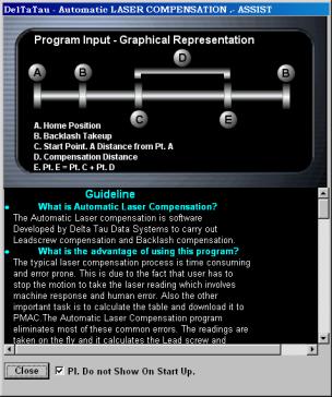
5 INTRODUCTION Laser Compensation using PMAC is now faster and more accurate in comparison to the conventional way. The typical laser compensation process is time consuming and error prone, because motion must be stopped to take the laser reading. This affects machine response and allows human error. The Automatic Laser Compensation program eliminates most of the common errors. The readings are taken on the fly and it calculates the Leadscrew and Backlash tables and then automatically downloads it to PMAC. With Manual Laser Compensation, the tables can be created and edited before downloading to PMAC. Concept The laser calibration program relies in the position compare and position capture feature of the PMAC motion controller. The motor under calibration uses the position compare to activate the EQU output signal at regular position intervals. This output triggers the position capture of the laser interferometer, which is read through an independent spare encoder channel. This technique, based on a highly precise hardwarecontrolled feature, allows creating a compensation table for each motor. In general, a spare encoder input is used to connect the laser interferometer quadrature encoder. In case no spare encoder input is available, an encoder input of a motor that is not currently being calibrated could be used temporarily. For a typical NC 4-axis machine, the Spindle channel can be used as a free channel. Then, the corresponding EQU line output that belongs to the motor under calibration is connected to the C channel input of the encoder channel used to connect the laser interferometer. The following examples show the connections for the most commonly used Delta Tau motion controllers. In PMAC boards, the JEQU connector is a 10-pin male header. In the UMAC accessories Acc-24E2x, the JEQU connector is a 3-pin terminal. Note: The indicated connections must be made every time an axis is selected for compensation. Board Name PMAC-Lite PCI PMAC1-PCI PMAC2-Lite PCI PMAC2-PCI Turbo PMAC-PCI UMAC Type of Connector on PMAC or UMAC J8 10 Pin Header J9 10 Pin Header J8 10 Pin Header J8 10 Pin Header J9 10 Pin Header TB3 top OR J1 (15 Pin DB male connector) top FOR DB option Example: A PMAC PCI board is used. Encoder channel #4 is used to connect the laser interferometer quadrature encoder. Motor #1 uses the encoder compare feature, triggering the EQU1/ at regular position intervals. The accessory board shown can be an Acc-8D, Acc-8P or any other breakout accessory board compatible with a PMAC board. Introduction 1
6 Laser Interferometer Encoder Connector Pin # Symbol 14 CHA4+ 16 CHA4-10 CHB4+ 12 CHB4-4 GND 6 CHC4+ ACC-8x Other Axes Selected Axis J9 - JEQU Pin # Symbol 1 EQU1/ 2 EQU2/ 3 EQU3/ PMAC-PCI Example: A PMAC2 board is used. Any spare encoder channel can be used to connect the laser interferometer quadrature encoder. Motor #1 uses the encoder compare feature, triggering the EQU1/ at regular position intervals. The accessory board shown can be an Acc-8E, Acc-8F or any other axis interface board compatible with a PMAC2 board. Laser Interferometer Encoder n Connector Pin # Symbol 1 CHAn+ 2 CHAn- 3 CHBn+ 4 CHBn- 8 GND 5 CHCn+ ACC-8x Other Axes Selected Axis JEQU Pin # Symbol 1 EQU1/ 2 EQU2/ 3 EQU3/ PMAC2 Example: A UMAC System is used. Any spare encoder channel can be used to connect the laser interferometer quadrature encoder. Motor #1 uses the encoder compare feature, triggering the BEQU1 at regular position intervals. The accessory board shown can be an Acc-24E2, Acc-24E2A or any other UMAC axis interface board with quadrature encoder inputs. 2 Introduction
7 Laser Interferometer TB1 Top Pin # Symbol 1 CHA+ 2 CHA- 3 CHB+ 4 CHB- 8 GND 5 CHC+ ACC-24E2x Other Axis Selected Axis TB3 Top Pin # Symbol 1 EQU1/ 2 EQU2/ ACC-24E2x Requirements Automatic Laser Compensation The following items are needed to run the Automatic Laser Program: Laser with A QUAD B output (not necessary for Manual Mode) Delta Tau s Automatic Laser Compensation Program (Window s 98, 2000, or NT operating system) Delta Tau s Turbo PMAC1/2 or PMAC1/2 Interfacing Cables Executive PRO Software to communicate with PMAC Laser Compensation Installation After the successful default installation, the directory structure will look like: C:\ Program Files \ Delta Tau \ Laser Compensation \ Laser_comp.exe C:\ Program Files \ Common Files \ Delta Tau Shared \ Lasercompdef.h Online Assist for Quick Start This function is available in Automatic Laser Compensation only. When the program is started, the main window displays along with the Assist window. The Assist window provides quick help for those wanting to use the application without the detailed manual. The Assist window consists of two sections. The first section outlines the steps to set up the Program Input and the second explains the meaning of the programming parameters with the help of diagram. Click Pl Do not show on Start up to prevent the display of the Assist window at the start of the application. Introduction 3
8 4 Introduction


9 PROGRAM SETUP Set up the program as follows: 1. Start the application by typing LASER.EXE. At the start of the program, the Welcome window displays. 2. Select the type of the compensation, either Automatic or Manual, and then click the Continue button. The PMAC Device Dialog Box displays. 3. Select the appropriate device and click OK. The Laser Compensation dialog box displays. See the Main Window section of this manual to proceed. Program Setup 5
10 6 Program Setup

11 AUTOMATIC LASER COMPENSATION EXECUTION Main Window Highlights Navigate the input by pressing Tab, or directly select the input by pressing Alt and the underlined letter. Single line help is available when the focus is set to the input field. Run time status displays in the Program Status group box. Fields The following outlines the different fields on the main screen. PMAC Type: This will detect and display the PMAC type automatically. This input cannot be altered. If there is no PMAC, then the default PMAC type will be Turbo PMAC 2. Machine Name: Enter a specific folder name for the application here, if desired. All the files created by the application are stored in this folder. The change can be observed in the Path input. The default name is MyLaser. Path: The default path to create the Machine Name folder is C:\Program Files \ Delta Tau \<Machine Name>. Browse to change the default path. Laser Setting: This important setting comes from the Laser manufacturer. This setting specifies the number of counts per unit of distance traveled. The Laser is required to have A QUAD B output. A typical method for calculating the number of pulses is 1/LAMBDA where LAMBDA is the wavelength of the laser. Automatic Laser Compensation Execution 7
12 PMAC Encoder Channel: This input specifies the PMAC channel used to connect Laser A QUAD B output. Usually, this is a free channel on PMAC. For the 4-axes system, the spindle encoder connection can be replaced by Laser A QUAD B connection. Program Input Section: Motor No: Specify the motor number selected for compensation. Comp Distance: Specify the compensation distance from the Start point. The laser reading will be taken on the fly over this distance. Set this distance so that Start Point + comp distance is not greater than total travel available on the machine, otherwise the machine limits will generate fault. No. of Repetitions: This field specifies the repetitions of readings. Multiple readings improve statistical validity of the measurements. Three is a good statistical value. The maximum value is 10. Feed Rate: Enter the feedrate at which the selected motor will move in units per minute. No of Readings: Enter the number of intervals at which the laser reading will be taken. For the Turbo PMAC, this limit is 500 points and for Non-Turbo, it is 200. Start Point: Enter the absolute distance from Home position. The compensation readings will start from this point and end at Start Point + comp Distance. This value should be large enough to accommodate Backlash Take up distance. Backlash Take Up Distance: This field specifies the distance from the start point to move so that motor motion will get rid of the backlash and backlash will not affect the first reading. This value should not be set to a value greater then zero. Start Direction: This is the direction of the motion. Normally this is opposite of the Homing direction. Compensation: This value differentiates between the creation of the table and the verification of the table. Normally, this checkbox is not clicked the first time the program is run, so that the compensation readings will accurate. This box can be checked after the data is collected and tables are downloaded to PMAC. This is for the verification of the compensation table. The box will be checked automatically on table download. Program Status: This group of boxes represents the parameters, which are displayed during the data collection run. Program Axis: This field shows the axis associated with the input motor number. Data Points: This is the current number of the reading. Capture Position: This is current data captured on the fly. Repetitions: This is the current repetition number. Increment: This increment field (Comp Distance/ No of readings) displays the trigger distance at which data will be captured on the fly. Program Data: This group of boxes represents the input set usually after the first data collection run. Select Table: This group of boxes represents the type of table to be created for the selected motor. Lead screw: Click to generate the Lead screw compensation table when the download key is clicked. Correction Source: Backlash: Click to generate the Backlash compensation table when the download key is clicked. Clear Table: This group of boxes represents the type of table to be deleted from PMAC for the selected motor. Leadscrew: Click to delete the Lead screw table on Clear key. Backlash: Click to delete the Backlash table on Clear key. Plot: Selecting this button will plot the current captured data. The plot can be re-scaled. 8 Automatic Laser Compensation Execution
13 Download: Selecting this button will generate the selected comp tables from the select table and those tables will be downloaded to PMAC. After download, this button will be grayed out until one data collection cycle executes. Show: Clicking this button will display the current data in tabular form. Control Buttons Section: Run: Click this button to start the motion program to capture data on the fly. Test: Click this button to match the encoder counting direction of selected axis and the laser axis. The encoder counting direction for the selected axis and laser (A QUAD B) encoder counting direction must be the same. Help: Click this button to get Online Quick Help to explain the Program Input. File Management The following files are generated from this application in the Path \ Machine Name folder. Axis<Motor No>_comp.pmc -: Lead screw compensation file for the motor number (e.g. Axis1_comp.pmc). Axis<Motor No>_blcomp.pmc -: Backlash compensation file for the motor number (e.g. Axis1_blcomp.pmc). <Axis Char>_comp_<repeat counter>.txt -: Data collection file (e.g. X_comp_1.txt). <Axis Char>_RMS_<Motor No>.txt -: Tabular data display file (e.g. X_RMS_1.pmc). Laser_comp.pmc and Laser_comp.plc are the motion program and plc files used in the application. Executing Automatic Laser Compensation To execute the automatic program, use the following seven steps: 1. Clear all tables. 2. Set Program Input group. 3. Start data collection. 4. Select type of compensation and download. 5. Verify backlash compensation. 6. Select type of compensation and download. 7. Verify leadscrew and backlash compensation. Step 1 Clear all the tables from the PMAC by selecting tables in the Clear Table group and clicking the Clear button. Step 2 Set Program Input group. 1. The compensation is for Motor No 1 at 100 inch/min Feed Rate. 2. The distance to be compensated is (Comp. Distance) 16 inches and No. Of Readings are 16. Thus the readings are taken at every inch. 3. The first data point is at 1 inch (Start Point). 4. The data will be collected for 3 cycles (No. Of Repetitions) and direction of the motion is Negative. All the output files are stored under C:\Program Files\Delta Tau\HAAS folder. Step 3 Click the Run key to start data collection. This will generate the following motion program and PLC. Motion Program Generated for the HAAS Machine This Program is designed to process the Automatic Position Compare - Capture for leadscrew compensation. Include the LaserCompDef.h file. Automatic Laser Compensation Execution 9
14 DATA_READY_2_UPLOAD = 0 FEED_RATE = 50 P_WIDTH =2 COMP_REPETATIONS = 3 COMP_DISTANCE = NO_OF_READINGS = 16 START_DISTANCE = START_DIRECTION = -1 BACKLASH_DISTANCE = Direction1 =0 Direction2 =0 I51 = 0 Comp1_correction = 0 Q = 0 I186 = 0 I185 = 0 Ix86_constant = 0 OPEN PROGRAM 100 CLEAR TEMP1 = LKHD_MODE LKHD_MODE = 0 TEMP2 = ACC_TIME_TA ERROR_NUMBER = 0 Pointer_to_P_Base =2000 ENC1_COMP_A_M = ENC1_COUNTER_M + (30 * * START_DIRECTION) ENC1_COMP_B_M = ENC1_COMP_A_M + (P_WIDTH * START_DIRECTION) IF (ENC1_COMP_A_M > ) ENC1_COMP_A_M = * START_DIRECTION ENC1_COMP_B_M = ENC1_COMP_A_M + (P_WIDTH * START_DIRECTION) ENDIF START_L_SCREW_COMP = 0 DATA_READY_2_UPLOAD = 0 Program_End = 0 CMD "EQU1_COMPARE_OUTPUT_M = 0 ENC1_COMP_LATCH_CNTL_M = 1" DWELL200 P2000 = ENC7_CAPTURE_M P2000= 0 CMD "DIS PLCC0" CMD "ENA PLCC0" INCREMENT = 0 ENC1_COMP_ATINCR_M = 0 IF (HOME_COMPLETE_1_M = 0) ERROR_NUMBER = 1 GOTO 1 ENDIF TEMP4 = COMP_DISTANCE/NO_OF_READINGS INCREMENT = TEMP4 * TEMP5 = NO_OF_READINGS TEMP8 = COMP_REPETATIONS Pointer_to_Q1000 = 1000 Pointer_to_Q2000 = 2000 TA(100) Feed1 = (FEED_RATE * 30) /100 LINEAR ABS F(Feed1) 10 Automatic Laser Compensation Execution
15 X(START_DISTANCE * START_DIRECTION) DWELL200 WHILE (IN_POSITION_M = 0 OR DES_VEL_ZERO_1_M=0) ENDWHILE DWELL1000 INC X(START_DIRECTION * -1 * BACKLASH_DISTANCE ) DWELL1000 WHILE (IN_POSITION_M = 0 OR DES_VEL_ZERO_1_M=0) ENDWHILE DWELL1000 WHILE (TEMP8!= 0) Pointer_to_P_Base = 2000 TEMP3 = START_DIRECTION Incremental_counter =INCREMENT ENC1_COMP_A_M = ENC1_COUNTER_M +(BACKLASH_DISTANCE * *START_DIRECTION) + Q1000_Pointer+Ix86_constant+Q2000_Pointer ENC1_COMP_B_M = ENC1_COMP_A_M + (P_WIDTH * START_DIRECTION) CMD "EQU1_COMPARE_OUTPUT_M = 0 ENC1_COMP_LATCH_CNTL_M = 1" Pointer_to_Q1000=Pointer_to_Q Pointer_to_Q2000 = Pointer_to_Q First_Data_POINT = ENC1_COUNTER_M + (BACKLASH_DISTANCE * * START_DIRECTION) DWELL200 Direction1 = 1 START_L_SCREW_COMP = 1 Pos_Reading_Counter = 0 INC F(FEED_RATE) X((COMP_DISTANCE + BACKLASH_DISTANCE+ BACKLASH_DISTANCE) * START_DIRECTION) DWELL200 WHILE (IN_POSITION_M = 0 OR DES_VEL_ZERO_1_M=0) ENDWHILE WHILE (Direction1 = 1) ENDWHILE START_L_SCREW_COMP = 0 TEMP3 = TEMP3 * -1 ENC1_COMP_A_M = ENC1_COUNTER_M +(30 * * TEMP3) ENC1_COMP_B_M = ENC1_COMP_A_M + (P_WIDTH * TEMP3) IF (ENC1_COMP_A_M > ) ENC1_COMP_A_M = * TEMP3 ENC1_COMP_B_M = ENC1_COMP_A_M + (P_WIDTH * TEMP3) ENDIF ENC1_COMP_A_M = First_Data_POINT -(Incremental_counter * TEMP3) + Q1000_Pointer ENC1_COMP_B_M = ENC1_COMP_A_M - (P_WIDTH * TEMP3) CMD "EQU1_COMPARE_OUTPUT_M = 0 ENC1_COMP_LATCH_CNTL_M = 1" DWELL200 Direction2 = 1 START_L_SCREW_COMP = 1 Pos_Reading_Counter = 0 F(FEED_RATE) X((Comp_Distance+Backlash_Distance+Backlash_Distance) * Start_Direction* -1) DWELL200 WHILE (IN_POSITION_M = 0 OR DES_VEL_ZERO_1_M=0) Automatic Laser Compensation Execution 11
16 ENDWHILE WHILE (Direction2 = 1) ENDWHILE START_L_SCREW_COMP = 0 TEMP8=TEMP8-1 CAPTURE_AT_HOME = P2000 DATA_READY_2_UPLOAD = 1 DWELL750 ENC1_COMP_A_M = ENC1_COUNTER_M + (30 * * START_DIRECTION) ENC1_COMP_B_M = ENC1_COMP_A_M + (P_WIDTH * START_DIRECTION) IF (ENC1_COMP_A_M > ) ENC1_COMP_A_M = * START_DIRECTION ENC1_COMP_B_M = ENC1_COMP_A_M + (P_WIDTH * START_DIRECTION) ENDIF WHILE (DATA_READY_2_UPLOAD = 1) ENDWHILE CMD "EQU1_COMPARE_OUTPUT_M = 0 ENC1_COMP_LATCH_CNTL_M = 1" DWELL200 ENDWHILE N1 TEMP8 = COMP_REPETATIONS LKHD_MODE = TEMP1 Program_End = 1 TA(TEMP2) ACC_TIME_TA = TEMP2 CLOSE PLCC Generated for the HAAS Machine This is a PLCC0 for reading the COMPARE data on the fly for leadscrew compensation. Include the LaserCompDef.h file. Pointer_to_P_Base =2000 Current_Capture_Pos = 0 I7132 = 13 OPEN PLCC 0 CLEAR WHILE (START_L_SCREW_COMP =1) IF (Direction1 = 1) IF (ENC1_COUNTER_M < ENC1_COMP_B_M) P_Base_Pointer = ENC7_CAPTURE_M Current_Capture_Pos =ENC7_CAPTURE_M Pointer_to_P_Base = Pointer_to_P_Base +1 Pos_Reading_Counter = Pos_Reading_Counter + 1 IF (Pos_Reading_Counter =17) Direction1 = 0 Pointer_to_Q1000 = NO_OF_READINGS Pointer_to_Q2000 = 2000 ELSE Incremental_counter = INCREMENT * Pos_Reading_Counter ENC1_COMP_A_M = First_Data_POINT + (Incremental_counter * TEMP3)+Q(Pointer_to_Q1000)+Ix86_constant+Q(Pointer_to_Q2000) ENC1_COMP_B_M = ENC1_COMP_A_M + (P_WIDTH * TEMP3) Pointer_to_Q1000 = Pointer_to_Q Pointer_to_Q2000 = Pointer_to_Q ENDIF ENDIF ENDIF IF (Direction2 = 1) 12 Automatic Laser Compensation Execution
 Direction2 = 0 Pointer_to_Q1000 = 1000 Incremental_counter = INCREMENT ELSE Incremental_counter = Incremental_counter - INCREMENT Pointer_to_Q1000 = Pointer_to_Q1000-1")
17 IF (ENC1_COUNTER_M > ENC1_COMP_B_M) P_Base_Pointer = ENC7_CAPTURE_M Current_Capture_Pos =ENC7_CAPTURE_M Pointer_to_P_Base = Pointer_to_P_Base +1 Pos_Reading_Counter = Pos_Reading_Counter + 1 IF (Pos_Reading_Counter =17) Direction2 = 0 Pointer_to_Q1000 = 1000 Incremental_counter = INCREMENT ELSE Incremental_counter = Incremental_counter - INCREMENT Pointer_to_Q1000 = Pointer_to_Q ENC1_COMP_A_M = First_Data_POINT - (Incremental_counter * TEMP3)+Q(Pointer_to_Q1000) ENC1_COMP_B_M = ENC1_COMP_A_M - (P_WIDTH * TEMP3) ENDIF ENDIF ENDIF ENDWHILE CLOSE On completion of motion, Program End will display. At this point, the Show Data, Plot Data and Download functions are enabled from the Program Data group. Click Plot Data to display the Position Vs Error plot for the current run. The points in blue are the points collected in Forward Run and the points in yellow are the points collected in Reverse Run. The dark blue and red points are the average of Forward and Reverse run. Note: There is an extra point in reverse run at (0,0). This is not a true point data collected point. This point is for the reference. Automatic Laser Compensation Execution 13

18 Step 4 Select the type of compensation from Select Table Group and click the Download button. This will generate and download the selected table. In the example, the Backlash table is selected first. On completion of download, Comp Table ON will be checked true. Note: It is not necessary to select the tables one at a time. This is just an example to show the effect of compensation. Step 5 Click Run to verify the backlash compensation. The motion program will be executed and data will be collected. On completion, Program End will display. At this point, select Plot Data. The plot on the following window shows the effect of the backlash compensation. The forward and reverse data points are very close to each other. Compare this plot with that of the previous window. Note: There is an extra point in reverse run at (0,0). This is not a true data collected point. This point is for reference. A typical Backlash table generated from the program will look like: // // BackLash Table // // Machine Name : HAAS Pmac Type : PMAC_TURBO2 // File Path : C:\Program Files\Delta Tau\HAAS\Axis1_BLCOMP.PMC // Backlash Table Definition #1 DEF BLCOMP // Backlash Table Automatic Laser Compensation Execution
19 // Backlash count I186 = -902 Step 6 Select the type of compensation from the Select Table Group and click the Download button. This will generate and download the selected table. In the example, the Backlash table was selected in step four, so now select Leadscrew Compensation. (Deselect Backlash if PMAC Firmware is less than for Turbo or 1.16G for PMAC 1 / 2.) On completion of Download, Comp Table ON will be checked true. Step 7 Click Run to verify Leadscrew and Backlash compensation. The motion program will be executed and data will be collected. On completion, Program End will display. At this point, select Plot Data. The following window shows the effect of Leadscrew and Backlash compensation. The forward and reverse data points are very close to each other and to zero. Compare this plot with the previous plot. Note: There is an extra point in reverse run at (0,0). This is not a true data collected point. This point is for reference. Automatic Laser Compensation Execution 15

20 A typical Leadscrew table generated from the program will look like: // // LeadScrew Compensation Table // // Machine Name : HAAS Pmac Type : PMAC_TURBO2 // File Path : C:\Program Files\Delta Tau\HAAS\Axis1_COMP.PMC // Leadscrew Table Definition #1 DEF COMP // LeadScrew Table // Backlash count I186 = Automatic Laser Compensation Execution

21 MANUAL LASER COMPENSATION EXECUTION Manual Laser Compensation allows data to be input and plotted manually. Then the compensation table can be created and downloaded. This option does not need additional wiring or a laser with A QUAD B output. Main Screen Highlights Navigate through the input by pressing Tab or directly select the input by pressing Alt and underlined letter. Single line help is available when the focus is set to the input field. Fields The following outlines the different fields on the main screen. PMAC Type: This will detect and display the PMAC type automatically. This input cannot be altered. If there is no PMAC, then default PMAC type will be Turbo PMAC 2. Machine Name: Enter a specific folder name for the application here, if desired. All the files created by the application are stored in this folder. The change can be observed in the Path input. The default name is MyLaser. Path: The default path to create the Machine Name folder is C:\Program Files \ Delta Tau \<Machine Name>. Browse to change the default path. Program Input: This group of boxes consists of different input parameters required for the application. Motor No: Specify the motor number selected for compensation. Comp Distance: This field specifies the compensation distance from the Start point. The laser reading will be taken on the fly over this distance. Set this distance such that Start Point + comp distance is not greater than total travel available on the machine, otherwise the machine limits will generate fault. Manual Laser Compensation Execution 17
22 No of Readings: Specify the number of intervals at which the laser reading is taken. For the Turbo PMAC, this limit is 500 points and for Non Turbo, it is 200. Start Point: Enter the absolute distance from Home position. The compensation readings will start from this point and end at the Start Point + comp Distance. This value should be large enough to accommodate Backlash Take up distance. Start Direction: This is the direction of the motion. Normally this is opposite of the Homing direction. Program Data: This group of boxes represents the input set usually after the first data collection run. Select Table: This group of boxes represents the type of table to be created for the selected motor. Lead screw: Click to generate the Lead screw compensation table when the download key is clicked. Correction Source: Backlash: Click to generate the Backlash compensation table when the download key is clicked. Clear Table: This group of boxes represents the type of table to be deleted from PMAC for the selected motor. Lead screw: Click to delete the Lead screw table on Clear key. Backlash: Click to delete the Backlash table on Clear key. Plot: Clicking this button will plot the current captured data. The plot can be re-scaled. Plot will enable Download and Show button. Download: Clicking this button will generate the selected comp tables from the select table and those tables will be downloaded to PMAC. After download, this button will be grayed out until one data collection cycle executes. Show: Clicking this button will display the current data in tabular form. Control Buttons: Create: Clicking this button will create the data entry table. The table will consider the values in the No. of readings, Comp distance, start point and motor number fields to create the table. Load: Clicking this button will load the previously saved manual data file. The extension for the file is.las file. 18 Manual Laser Compensation Execution

. <Axis Char>_comp_<repeat counter>.txt -: Data collection file (e.g. X_comp_1.txt). <Axis Char>_RMS_<Motor No>.txt -: Tabular data display file (e.g. X_RMS_1.")
23 Create Screen The following screen displays when the Create button is selected. Load Screen The following screen displays when the Load button is selected. File Management The following files are generated from this application in the Path \ Machine Name folder. Axis<Motor No>_comp.pmc -: Lead screw compensation file for the motor number (e.g. Axis1_comp.pmc). Axis<Motor No>_blcomp.pmc -: Backlash compensation file for the motor number (e.g. Axis1_blcomp.pmc). <Axis Char>_comp_<repeat counter>.txt -: Data collection file (e.g. X_comp_1.txt). <Axis Char>_RMS_<Motor No>.txt -: Tabular data display file (e.g. X_RMS_1.pmc). Manual Laser Compensation Execution 19

24 Axis<Motor No>_comp.las -: Compensation data file for the motor number (e.g. X_COMP_1.las). Executing Manual Laser Compensation To execute the compensation program manually, complete the following steps: Start the application and select Manual laser compensation. The Manual Laser Compensation Dialog box displays. Step 1 Clear the tables from the PMAC by selecting the tables in Clear Table group and select the Clear button. Step 2 Set the Program Input group. 1. The compensation is for Motor No The distance to be compensated is (Comp. Distance) 5 inches and No. Of Readings are 5. Thus, the readings are taken at every inch. 3. The first data point is at 1 inch (Start Point). 4. Set the compensation Direction to negative. 5. Click the Create button to create the blank table ready for data entry. The table has two columns, Data Points and Axis <* >. The Axis character will be displayed by reading the coordinate system definition from the PMAC. Initially, the Axis column will be set with zeros. 6. Measure the laser equivalent of one inch and enter the reading in the AXIS column. Data Entry Screen Click Plot to display the Position Vs Error plot for the current Run. Note: There is an extra point in reverse run at (0,0). This is not a true data point. This point is for the reference. 20 Manual Laser Compensation Execution
25 1. Select the type of compensation from the Select Table Group and click the Download button. This will generate and download the selected table. The Leadscrew, Backlash or both can be selected for download. 2. Set the Compensation On (I50 = 1) flag in the PMAC using the Executive program and then take another set of readings to check effect of the compensation. This program allows appending of the Leadscrew and backlash table. If the table exists already for the same number of points and distance, then the new calculated values are appended to the existing table. Manual Laser Compensation Execution 21
^2 PMAC Laser Calibration v2.0
 ^1 SOFTWARE REFERENCE MANUAL ^2 PMAC Laser Calibration v2.0 ^3 Software Reference Manual ^4 3A0-LASERC-xSxx ^5 July 19, 2006 Single Source Machine Control Power // Flexibility // Ease of Use 21314 Lassen
^3 Installation Procedures for PMAC/UMAC/QMAC NC. ^ xIxx. ^5 October 30, 2003
 ^ INSTALLATION MANUAL ^ PMAC/QMAC/UMAC NC ^ Installation Procedures for PMAC/UMAC/QMAC NC ^ 00-600-xIxx ^ October 0, 00 Single Source Machine Control Power // Flexibility // Ease of Use Lassen Street Chatsworth,
^2 Accessory 8D Option 4A
 ^1 USER MANUAL ^2 Accessory 8D Option 4A ^3 150W Four Channel PWM Amplifier Board ^4 3Ax-602311-xUxx ^5 October 24, 2003 Single Source Machine Control Power // Flexibility // Ease of Use 21314 Lassen Street
^2 Accessory 8DCE ^1 USER MANUAL. ^3 CE Certified PC Board/Terminal Block. ^4 3Ax xUxx. ^5 October 27, 2003
 ^1 USER MANUAL ^2 Accessory 8DCE ^3 CE Certified PC Board/Terminal Block ^4 3Ax-602654-xUxx ^5 October 27, 2003 Single Source Machine Control Power // Flexibility // Ease of Use 21314 Lassen Street Chatsworth,
^2 Accessory 24V ^1 USER MANUAL. ^3 PMAC VME Axis Expansion Card. ^4 3Ax xUxx. ^5 October 15, 2003
 ^1 USER MANUAL ^2 Accessory 24V ^3 PMAC VME Axis Expansion Card ^4 3Ax-602226-xUxx ^5 October 15, 2003 Single Source Machine Control Power // Flexibility // Ease of Use 21314 Lassen Street Chatsworth,
^3 Analog Servo Interface Board for PMAC2A-PC104. ^4 3Ax Hxx. ^5 December 15, 2009
 ^1 HARDWARE REFERENCE MANUAL ^2 Accessory 8ES ^3 Analog Servo Interface Board for PMAC2A-PC104 ^4 3Ax-603673-1Hxx ^5 December 15, 2009 Single Source Machine Control Power // Flexibility // Ease of Use
^2 Accessory 8D Option 4
 ^ USER MANUAL ^2 Accessory 8D Option 4 ^3 40W Four Channel Linear Amplifier Board ^4 3Ax-602235-xUxx ^5 October 24, 2003 Single Source Machine Control Power // Flexibility // Ease of Use 234 Lassen Street
^2 Accessory 55E DeviceNet Option
 1^ USER MANUAL ^2 Accessory 55E DeviceNet Option ^3 Universal Field Bus Adapter Network (UNET) ^4 3A0-603485-DUxx ^5 October 23, 2003 Single Source Machine Control Power // Flexibility // Ease of Use 21314
^2UMAC-CPCIAccessory Cx Family
 ^1 HARDWARE REFERENCE MANUAL ^2UMAC-CPCIAccessory Cx Family ^3 Compact UBUS Backplane Boards ^4 4Ax-603617-xHxx ^5 January 28, 2003 Single Source Machine Control Power // Flexibility // Ease of Use 21314
^2 Accessory 42PCI ^1 USER MANUAL. ^3 PMAC2-PC MACRO Interface Board. ^4 3Ax xUxx. ^5 September 30, 2003
 ^1 USER MANUAL ^2 ^3 PMAC2-PC MACRO Interface Board ^4 3Ax-603503-xUxx ^5 September 30, 2003 i Single Source Machine Control Power // Flexibility // Ease of Use 21314 Lassen Street Chatsworth, CA 91311
^2 Accessory 8D Option 7
 ^1 USER MANUAL ^2 Accessory 8D Option 7 ^3 Resolver To Digital Converter Board ^4 307-0ACC85-xUxx ^5 September 1, 2004 Single Source Machine Control Power // Flexibility // Ease of Use 21314 Lassen Street
^2 Accessory 8D Option 2
 i ^1 USER MANUAL ^2 ^3 Voltage to Frequency Converter Board ^4 3Ax-602234-xUxx ^5 October 24, 2003 Single Source Machine Control Power // Flexibility // Ease of Use 21314 Lassen Street Chatsworth, CA 91311
^2 Accessory 54E ^1 USER MANUAL. ^3 UMAC USB Communications Accessory. ^4 3Ax xUxx. ^5 October 23, 2003
 ^1 USER MANUAL ^2 Accessory 54E ^3 UMAC USB Communications Accessory ^4 3Ax-603467-xUxx ^5 October 23, 2003 Single Source Machine Control Power // Flexibility // Ease of Use 21314 Lassen Street Chatsworth,
^2 Accessory 8TS ^1 USER MANUAL. ^3 Interface Board with ACC-28B for PMAC2A-PC/104. ^4 3T xUxx. ^5 July 6, 2005
 ^ USER MANUAL ^ Accessory TS ^ Interface Board with ACC-B for PMACA-PC/ ^ T0-0-xUxx ^ July, 00 Single Source Machine Control Power // Flexibility // Ease of Use Lassen Street Chatsworth, CA // Tel. ()
^2 PMAC-NC Designer Manual
 ^1 SOFTWARE REFERENCE MANUAL ^2 PMAC-NC Designer Manual ^3 SOFTWARE REFERENCE MANUAL ^4 500-603831-xSxx ^5 September 28, 2007 Single Source Machine Control Power // Flexibility // Ease of Use 21314 Lassen
^1 EZ-QMAC Setup Software
 ^1 EZ-QMAC Setup Software ^3 EZ- QMAC Manual ^4 5EZ-603506-xSxx ^5 January 1, 2003 Single Source Machine Control Power // Flexibility // Ease of Use 21314 Lassen Street Chatsworth, CA 91311 // Tel. (818)
^3 MLDT Interface Board. ^4 3Ax xUxx. ^5 October 15, 2003
 ^1 USER MANUAL ^2 Accessory 29 ^3 MLDT Interface Board ^4 3Ax-602243-xUxx ^5 October 15, 2003 Single Source Machine Control Power // Flexibility // Ease of Use 21314 Lassen Street Chatsworth, CA 91311
^3 Software User Manual. ^4 5xx-09WPRO-xSxx. ^5 January 28, 2003
 ^1 USER MANUAL ^2 PmacPlot ^3 Software User Manual ^4 5xx-09WPRO-xSxx ^5 January 28, 2003 Single Source Machine Control Power // Flexibility // Ease of Use 21314 Lassen Street Chatsworth, CA 91311 // Tel.
^2 TURBO PMAC2 PCI ULTRALITE
 ^1HARDWARE REFERENCE MANUAL ^2 TURBO PMAC2 PCI ULTRALITE ^3 Programmable Multi-Axis Controller ^4 4AX-603726-XHXX ^5 December 12, 2011 Single Source Machine Control Power // Flexibility // Ease of Use
^2 UMAC Quick Reference
 ^1 Reference Guide ^2 UMAC Quick Reference ^3 Reference Guide for UMAC Products ^4 3A0-UMACQR-xPRx ^5 December 23, 2004 Single Source Machine Control Power // Flexibility // Ease of Use 21314 Lassen Street
UMAC Guide PUB NE 60th Way Vancouver, WA Voice Fax
 UMAC Guide PUB-0001-06 12000 NE 60th Way Vancouver, WA 98682 Voice 360.253.4810 Fax 360.253.4818 www.appliedmotionsystems.com 2007 Applied Motion Systems, Inc. All rights reserved. No part of this document
Copyright Information Delta Tau Data Systems, Inc. Technical Support Operating Conditions
 ^1 HARDWARE REFERENCE MANUAL ^2 PMAC2 PC Ultralite ^3 Programmable Multi-Axis Controller ^4 3Ax-602415-xHxx ^5 June 7, 2004 Single Source Machine Control Power // Flexibility // Ease of Use 21314 Lassen
^2 Accessory 34AA ^1 USER MANUAL. ^3 Opto 32-Bit Input/ 32-Bit Output Board. ^4 3Ax xUxx. ^5 July 6, 2004
 ^1 USER MANUAL ^2 Accessory 34AA ^3 Opto 32-Bit Input/ 32-Bit Output Board ^4 3Ax-602817-xUxx ^5 July 6, 2004 Single Source Machine Control Power // Flexibility // Ease of Use 21314 Lassen Street Chatsworth,
^3 Operating Instructions. ^4 3Ax-ACC33N-xUx0. ^5 September 30, 2003
 ^1 USER MANUAL ^2 PMAC NC ^3 Operating Instructions ^4 3Ax-ACC33N-xUx0 ^5 September 30, 2003 Single Source Machine Control Power // Flexibility // Ease of Use 21314 Lassen Street Chatsworth, CA 91311 //
^2 Accessory 36E ^1 USER MANUAL. DELTA TAU Data Systems, Inc. ^3 Analog I/O 16 x 12-bit Inputs ^4 3AX XUXX. ^5 February 24, 2014
 ^1 USER MANUAL ^2 Accessory 36E ^3 Analog I/O x 12-bit Inputs ^4 3AX-603483-XUXX ^5 February 24, 2014 DELTA TAU Data Systems, Inc. NEW IDEAS IN MOTION Single Source Machine Control...... Power // Flexibility
Installing Your 1394 Drive Interface Module
 Installation Instructions Installing Your Drive Interface Module (Catalog Number -DIM) Introduction This publication provides installation instructions for adding the Drive Interface Module to your system.
^2 PMAC2 PCI ^1 HARDWARE REFERENCE MANUAL. ^3 PMAC 2 PCI Bus Expansion Card. ^4 4XX xHxx. ^5 May 26, 2004
 ^1 HARDWARE REFERENCE MANUAL ^2 PMAC2 PCI ^3 PMAC 2 PCI Bus Expansion Card ^4 4XX-603486-xHxx ^5 May 26, 2004 Single Source Machine Control Power // Flexibility // Ease of Use 21314 Lassen Street Chatsworth,
^2 PMAC PCI ^1HARDWARE REFERENCE MANUAL. ^3 PCI-Bus Expansion w/piggyback CPU ^4 4A ^5 June 18, 2010
 ^1HARDWARE REFERENCE MANUAL ^2 PMAC PCI ^3 PCI-Bus Expansion w/piggyback CPU ^4 4A0-603588-100 ^5 June 18, 2010 Single Source Machine Control Power // Flexibility // Ease of Use 21314 Lassen Street Chatsworth,
^2 Turbo PMAC ^1 USER MANUAL. ^3 Programmable Multi Axis Controller. ^4 3Ax TUxx. ^5 October 5, 2004
 ^1 USER MANUAL ^2 Turbo PMAC ^3 Programmable Multi Axis Controller ^4 3Ax-602264-TUxx ^5 October 5, 2004 Single Source Machine Control Power // Flexibility // Ease of Use 21314 Lassen Street Chatsworth,
VT-50. Linear Positioning Stage Reference Manual. S e r i e s. (Open and Closed Loop Versions)
") VT-50 S e r i e s Linear Positioning Stage (Open and Closed Loop Versions) VT-50L Linear Stage Rev 1.03 MICRONIX USA, LLC 15375 Barranca Parkway, E-106 Irvine, CA 92618 Tel: 949-480-0538 Fax: 949-480-0538
VT-50 S e r i e s Linear Positioning Stage (Open and Closed Loop Versions) VT-50L Linear Stage Rev 1.03 MICRONIX USA, LLC 15375 Barranca Parkway, E-106 Irvine, CA 92618 Tel: 949-480-0538 Fax: 949-480-0538
^2 Accessory 53E ^1 USER MANUAL. ^4 3Ax xUxx. ^5 September 30, ^3 SSI (Synchronous Serial) Encoder Interface Board
 Encoder Interface Board") ^1 USER MANUAL ^2 Accessory 53E ^3 SSI (Synchronous Serial) Encoder Interface Board ^4 3Ax-603360-xUxx ^5 September 30, 2009 Single Source Machine Control Power // Flexibility // Ease of Use 21314 Lassen
^1 USER MANUAL ^2 Accessory 53E ^3 SSI (Synchronous Serial) Encoder Interface Board ^4 3Ax-603360-xUxx ^5 September 30, 2009 Single Source Machine Control Power // Flexibility // Ease of Use 21314 Lassen
UMAC Guide PUB NE 60th Way Vancouver, WA Voice Fax
 UMAC Guide PUB-0001-07 12000 NE 60th Way Vancouver, WA 98682 Voice 360.253.4810 Fax 360.253.4818 www.appliedmotionsystems.com 2007-2009 Applied Motion Systems, Inc. All rights reserved. No part of this
Axes Pairing Overview
 Axes Pairing Overview For the most part, this document pertains to all versions of CNC10 although some features discussed are available only in CNC10v 2.63 and above. For differences between your version
Preliminary Documentation. ^4 4XX xHxx. ^5 November 5, 2003
 ^1 HARDWARE REFERENCE MANUAL ^2 PMAC2 PCI Lite Preliminary Documentation ^3 PMAC 2 PCI Lite Bus Expansion Card ^4 4XX-603658-xHxx ^5 November 5, 2003 Single Source Machine Control Power // Flexibility
PMX Support FAQ There may be a few different causes to this issue. Check each item below:
 PMX Support FAQ USB Support What is the USB communication speed? The time interval between sending and command from a PC and receiving a response is 1-3ms. This applies to most commands. Commands dealing
(X 2,Y 2 ) (X 1,Y 1 ) (X 0,Y 0 ) (X c,y c ) (X 3,Y 3 )
 (X 1,Y 1 ) (X 0,Y 0 ) (X c,y c ) (X 3,Y 3 )") Application Note Nov-2004 Probing for Dimensional Analysis This example shows how you can use Turbo PMAC s move-until-trigger function with the super-fast hardware position capture to find the exact location
Application Note Nov-2004 Probing for Dimensional Analysis This example shows how you can use Turbo PMAC s move-until-trigger function with the super-fast hardware position capture to find the exact location
A Axis M-Functions Level 1 A Axis Standard A Axis SMT Level 2. Each console includes the following:
 Hardware List The 3000M Crusader II Upgrade system has been custom configured to provide the necessary hardware required for installation on your machine. Verify that you have received all the correct
TB048 (Rev1) - Laser Mapping Procedure (Software Versions Prior to 2.61)
 - Laser Mapping Procedure (Software Versions Prior to 2.61)") TB048 (Rev1) - Laser Mapping Procedure (Software Versions Prior to 2.61) Overview This document describes how to use a laser for ball screw mapping with CNC7 version 7.17 to CNC10 version 2.61. It assumes
TB048 (Rev1) - Laser Mapping Procedure (Software Versions Prior to 2.61) Overview This document describes how to use a laser for ball screw mapping with CNC7 version 7.17 to CNC10 version 2.61. It assumes
^3 Software User Manual. ^4 5xx-09WPRO-xSxx. ^5 January 28, 2003
 ^1 SOFTWARE USER MANUAL ^2 PmacPlot ^3 Software User Manual ^4 5xx-09WPRO-xSxx ^5 January 28, 2003 Single Source Machine Control Power // Flexibility // Ease of Use 21314 Lassen Street Chatsworth, CA 91311
^2 Turbo PMAC PCI ^1 HARDWARE REFERENCE MANUAL. ^3 PC Bus Expansion Board with Piggyback CPU. ^4 4xx xHxx.
 ^1 HARDWARE REFERENCE MANUAL ^2 Turbo PMAC PCI ^3 PC Bus Expansion Board with Piggyback CPU ^4 4xx-603588-xHxx ^5 April 27, 2010 Single Source Machine Control Power // Flexibility // Ease of Use 21314
DO NOT POWER ON THE ZEBRA PRINTER OR CONNECT THE USB CABLE UNTIL INSTRUCTED TO DO SO!
 1 EnviroMap Zebra Setup Utilities Installation, Local Print Client Installation, &.ZPL File Association for Zebra GX420d Printers Connected via USB Cable The steps outlined below must be followed the first
MRZJW3- SETUP154E. General-Purpose AC Servo Servo Configuration Software MODEL INSTALLATION GUIDE
 General-Purpose AC Servo Servo Configuration Software MODEL MRZJW3- SETUP154E INSTALLATION GUIDE Thank you for choosing the Mitsubishi general-purpose AC servo Servo Configuration Software. To optimize
1Developer's. Quick Start Power PMAC NC 2014
 1Developer's Quick Start Power PMAC NC 2014 Delta Tau Data Systems, Inc. June, 2015 1 COPYRIGHT INFORMATION Software: 2014 Delta Tau Data Systems, Inc. All rights reserved. Software User Manual: 2014 Delta
Contents. Introduction... iii. CHAPTER 1 - Getting Started... 5
 Transducer Characterization User s Guide Version 5 5 1 build 12 or later UTEX Scientific Instruments Inc support@utex com Winspect Transducer Characterization User s Guide Contents Table of Contents and
^2 Turbo PMAC PCI-Lite
 ^1 HARDWARE REFERENCE MANUAL ^2 Turbo PMAC PCI-Lite ^3 Programmable Multi-Axis Controller ^4 4xx-603657-THxx ^5 June 17, 2003 Single Source Machine Control Power // Flexibility // Ease of Use Table 21314
^2 PMAC-NC Pro2 ^1 SOFTWARE REFERENCE. ^3 Software Reference Manual. ^4 3Ax-NC32V5-xSxx. ^5 August 10, 2012
 ^1 SOFTWARE REFERENCE ^2 PMAC-NC Pro2 ^3 Software Reference Manual ^4 3Ax-NC32V5-xSxx ^5 August 10, 2012 Single Source Machine Control Power // Flexibility // Ease of Use 21314 Lassen Street Chatsworth,
First Steps in Commissioning CPU. 31xC: Positioning with digital output SIMATIC
 First Steps in Commissioning CPU 31xC: Positioning with digital output Introduction 1 Preparation 2 SIMATIC S7-300 First Steps in Commissioning CPU 31xC: Positioning with digital output Learning units
D115 The Fast Optimal Servo Amplifier For Brush, Brushless, Voice Coil Servo Motors
 D115 The Fast Optimal Servo Amplifier For Brush, Brushless, Voice Coil Servo Motors Ron Boe 5/15/2014 This user guide details the servo drives capabilities and physical interfaces. Users will be able to
Computer Numerical Control for Windows Version 1.2. User s Guide
 Computer Numerical Control for Windows Version 1.2 User s Guide 1998 FlashCut CNC, Inc. 1263 El Camino Real, Suite W, Menlo Park, CA 94025 Phone (650) 853-1444 Fax (650) 853-1405 www.flashcutcnc.com Table
Preliminary Documentation. ^3 16-Axis MACRO CPU. ^4 4Ax xHxx. ^5 April 21, 2010
 ^1 HARDWARE REFERENCE MANUAL ^2 16-Axis MACRO CPU Preliminary Documentation ^3 16-Axis MACRO CPU ^4 4Ax-603719-xHxx ^5 April 21, 2010 Single Source Machine Control Power // Flexibility // Ease of Use 21314
PPS-28. Precision Piezo Stage Reference Manual. S e r i e s. (Open and Closed Loop Versions)
") PPS-28 S e r i e s Precision Piezo Stage (Open and Closed Loop Versions) PPS-28 Piezo Positioner Stage Rev 3.02 MICRONIX USA, LLC 15375 Barranca Parkway, E-106 Irvine, CA 92618 Tel: 949-480-0538 Fax: 949-480-0538
PPS-28 S e r i e s Precision Piezo Stage (Open and Closed Loop Versions) PPS-28 Piezo Positioner Stage Rev 3.02 MICRONIX USA, LLC 15375 Barranca Parkway, E-106 Irvine, CA 92618 Tel: 949-480-0538 Fax: 949-480-0538
Ultimate Screen Reference Guide
 MACHMOTION Ultimate Screen Reference Guide 8/11/2011 Everything you need to know to use and setup the MachMotion Ultimate Screen. MachMotion Version 1.0.2 2 P a g e Copyright 2011, MachMotion.com All rights
^2 PMAC ^1 USER MANUAL. ^3 Programmable Multi-Axis Controller. ^4 3Ax xUxx. ^5 June 3, 2003
 ^1 USER MANUAL ^2 PMAC ^3 Programmable Multi-Axis Controller ^4 3Ax-602264-xUxx ^5 June 3, 2003 Single Source Machine Control Power // Flexibility // Ease of Use 21314 Lassen Street Chatsworth, CA 91311
Motion Controller. MXC Series Multi-Axis Motion Controller Compact Motion Controller with up to 6 Axes of Control
 MXC Series Multi-Axis Motion Controller Compact Motion Controller with up to 6 Axes of Control Allied Motion s MXC motion controller is a very compact, multi-axis servo and/or step motor motion controller,
Apollo III INSTALLATION MANUAL
 Apollo III INSTALLATION MANUAL 2 P a g e 5/1/14 N0112 This manual covers the setup and configuration of the Apollo III motion controller connected to the control using Mach3. Formatting Overview: Menus,
CNCcomp 4.5. CNC pitch compensation program. User Manual. Copyrights: Tampere University of Technology. Production engineering. Qplus Ltd.
 CNCcomp 4.5 CNC pitch compensation program User Manual Copyrights: Tampere University of Technology Production engineering Qplus Ltd. The software is developed by Qplus Ltd: Qplus Ltd. PL 70 33721 TAMPERE
micromax R Getting Started Guide
 PN# 34-2114 Rev 1 04-25-2007 micromax R Introduction Introduction Thank you for purchasing Agile System s micromax R product. This guide covers how to install DPWin, connect, configure and tune a motor
Manual DTM Digital Pressure Transmitter
 TetraTec Instruments GmbH Gewerbestr. 8 71144 Steinenbronn Deutschland E-Mail: info@tetratec.de Tel.: 07157/5387-0 Fax: 07157/5387-10 Manual Digital Pressure Transmitter *** VERSION 1.1 *** Update: 22.11.2006
^2 Turbo PMAC / PMAC2
 ^1 SOFTWARE REFERENCE MANUAL ^2 Turbo PMAC / PMAC2 ^3 V1.941 V1.945 Firmware Addendum ^4 3Ax-01.942-xSxx ^5 August 28, 2008 Single Source Machine Control Power // Flexibility // Ease of Use 21314 Lassen
^2 PMAC Quick Reference
 1^ REFERENCE GUIDE ^2 PMAC Quick Reference ^3 Reference Guide for PMAC Products ^4 3A0-PMACQR-xPRx ^5 September 29, 2009 USER MANUAL Single Source Machine Control Power // Flexibility // Ease of Use 21314
Date 18/05/17. Operation and maintenance instructions for driver configurator QSet
 Operation and maintenance instructions 28 1. General recommendations The recommendations regarding safe use in this document should be observed at all times. Some hazards can only be associated with the
ZETA6104. Linear Microstepping Motor/Drive Systems. Packaged Drive/Indexer System with L20 Perspective. C Step Motor Systems C81. Catalog /USA
 ZETA6104 Packaged Drive/Indexer System with L20 Perspective Compumotor s ZETA6104 is a stand-alone, single-axis drive/ indexer system. The ZETA6104 packs all the power and reliability of the 6000 family
^1 HARDWARE REFERENCE MANUAL
 ^1 HARDWARE REFERENCE MANUAL ^2 PMAC STD ^3 Programmable Multi-Axis Controller ^4 4Ax-602409-xHxx ^5 January 28, 2003 Single Source Machine Control Power // Flexibility // Ease of Use 21314 Lassen Street
Artisan Technology Group is your source for quality new and certified-used/pre-owned equipment
 Artisan Technology Group is your source for quality new and certified-used/pre-owned equipment FAST SHIPPING AND DELIVERY TENS OF THOUSANDS OF IN-STOCK ITEMS EQUIPMENT DEMOS HUNDREDS OF MANUFACTURERS SUPPORTED
^2 PMAC-NC Pro2 ^1 SOFTWARE REFERENCE. ^3 Software Reference Manual. ^4 3Ax-NC32V5-xSxx. ^5 October 10, 2006
 ^1 SOFTWARE REFERENCE ^2 PMAC-NC Pro2 ^3 Software Reference Manual ^4 3Ax-NC32V5-xSxx ^5 October 10, 2006 Single Source Machine Control Power // Flexibility // Ease of Use 21314 Lassen Street Chatsworth,
Installation Instructions for: Channel Thermocouple Amplifier
 Installation Instructions for: 30-2204 4 Channel Thermocouple Amplifier The Advanced Engine Management (AEM) 4 channel thermocouple amplifier revolutionizes temperature measurements by providing laboratory
DELTA TAU DATA SYSTEMS, INC. POWER PMAC UMAC CPU BOARD HARDWARE REFERENCE
 DELTA TAU DATA SYSTEMS, INC. ` POWER PMAC UMAC CPU BOARD HARDWARE REFERENCE DOCUMENT # 3A0-604020-360 PRELIMINARY May, 2009 Delta Tau Data Systems 21314 Lassen St. Chatsworth, CA 91311 Ph: (818) 998-2095
ION Demo Kit. Quick Start Guide PERFORMANCE MOTION DEVICES
 ION Demo Kit Quick Start Guide PERFORMANCE MOTION DEVICES 1.0 Introduction This guide will help you get your ION Demo Kit up and running quickly. Please follow the instructions below. The kit includes
UNIVERSAL MOTION INTERFACE (UMI) ACCESSORY
 ACCESSORY") USER GUIDE UNIVERSAL MOTION INTERFACE (UMI) ACCESSORY Contents This user guide describes how to use the UMI-77, UMI-A, UMI-Flex, and UMI-Flex accessories. Introduction... What You Need to Get Started...
USER GUIDE UNIVERSAL MOTION INTERFACE (UMI) ACCESSORY Contents This user guide describes how to use the UMI-77, UMI-A, UMI-Flex, and UMI-Flex accessories. Introduction... What You Need to Get Started...
PP-BOB2-V1.0 PARALLEL PORT BREAKOUT BOARD
 PP-BOB2-v1 PARALLEL PORT BREAKOUT BOARD Document: Operation Manual Document #: T17 Document Rev: 2.0 Product: PP-BOB2-v1.0 Product Rev: 1.0 Created: March, 2013 Updated: Dec, 2014 THIS MANUAL CONTAINS
Service Bulletin 147B
 DATA I/O Corporation 10525 Willows Road NE Redmond, WA 98052 Phone: 1.425.881.6444 Phone: 1.800.247.5700 (press 2) FAX: 425.867.6972 support@dataio.com Subject: PnP (SMAC) Head Tuning Guide This document
Flow Computer. Manual Configuration of Device Software. FC1-CDS-EN b i From ensuite version 3.4
 Flow Computer encore FC1 Manual Configuration of Device Software FC1-CDS-EN b 2015-11-18 i 2015-11-18 From ensuite version 3.4 Elster GmbH Schloßstraße 95a D - 44357 Dortmund/Germany Tel.: +49 231 937110-0
Electromechanical Automation Applications Note
 Electromechanical Automation Applications Note Product: Trilogy coils & Positioners Rev: 1.0 Subject: Wiring and Setup of Trilogy to AriesEPL with ACR9040 or AriesCE This applications note clarifies the
^3 PMAC Panel. ^4 3A0-9PLPRO-xUxx. ^5 July 2003
 ^1 USER MANUAL ^2 PMAC Panel ^3 PMAC Panel ^4 3A0-9PLPRO-xUxx ^5 July 2003 Single Source Machine Control Power // Flexibility // Ease of Use 21314 Lassen Street Chatsworth, CA 91311 // Tel. (818) 998-2095
Datasheet MX Axis Stepper Drive with Breakout Board & I/O s. Version
 Datasheet MX3660 3-Axis Stepper Drive with Breakout Board & I/O s Version 1.1 http://www.leadshine.com http://www.leadshineusa.com 2013 Leadshine Technology Co., Ltd. Notice This manual is not for use
PP-BOB2-V2.0 PARALLEL PORT BREAKOUT BOARD
 PP-BOB2-V2 PARALLEL PORT BREAKOUT BOARD Document: Operation Manual Document #: T18 Document Rev: 1.0 Product: PP-BOB2-V2.0 Product Rev: 1.0 Created: October, 2015 THIS MANUAL CONTAINS INFORMATION FOR INSTALLING
PR-32. Piezo Rotation Stage Reference Manual. S e r i e s. (Open and Closed Loop Versions)
") PR-32 S e r i e s Piezo Rotation Stage (Open and Closed Loop Versions) PR-32 Piezo Rotation Stage Rev 3.00 MICRONIX USA, LLC 15375 Barranca Parkway, E-106 Irvine, CA 92618 Tel: 949-480-0538 Fax: 949-480-0538
PR-32 S e r i e s Piezo Rotation Stage (Open and Closed Loop Versions) PR-32 Piezo Rotation Stage Rev 3.00 MICRONIX USA, LLC 15375 Barranca Parkway, E-106 Irvine, CA 92618 Tel: 949-480-0538 Fax: 949-480-0538
Apollo I Breakout Board User s Manual
 MACHMOTION Apollo I Breakout Board User s Manual 1/14/2012 Everything you need to know to set up and use your Apollo I Breakout Board. MachMotion Version 1.0.1 2 P a g e M a c h M o t i o n Copyright 2012,
Navigator Software User s Manual. User Manual. Navigator Software. Monarch Instrument Rev 0.98 May Page 1 of 17
 User Manual Navigator Software Monarch Instrument Rev 0.98 May 2006 Page 1 of 17 Contents 1. NAVIGATOR SOFTWARE 2. INSTALLATION 3. USING NAVIGATOR SOFTWARE 3.1 STARTING THE PROGRAM 3.2 SYSTEM SET UP 3.3
Galil Motion Control. DMC - 18x6. Datasheet (US ONLY)
") Galil Motion Control DMC - 18x6 Datasheet Galil Motion Control 270 Technology Way, Rocklin, CA 1-916-626-0101 (US ONLY) 1-800-377-6329 Product Description The DMC-18x6 PCI bus motor controllers belong
Galil Motion Control DMC - 18x6 Datasheet Galil Motion Control 270 Technology Way, Rocklin, CA 1-916-626-0101 (US ONLY) 1-800-377-6329 Product Description The DMC-18x6 PCI bus motor controllers belong
MPU User Guide Updated 3/11/15. Overview
 MPU11 090212 User Guide Updated 3/11/15 Overview The MPU11 is Centroid s next generation motion control card. It supports greater communication bandwidth with new protocols and more processing power. MPU11
INTEGRATED MICROSTEPPING MOTOR DRIVER AND HIGH PERFORMANCE MACHINE/PROCESS CONTROLLER
 Sold by Servo Systems Co. 115 Main Road, P.O. Box 97, Montville, NJ 07045-0097 Toll Free: (800) 922-1103 Phone: (973) 335-1007 Fax: (973) 335-1661 www.servosystems.com INTEGRATED MICROSTEPG MOTOR DRIVER
Chapter 5 SDM-20240/20242
 Chapter 5 SDM-20240/20242 Introduction The SDM-20240 and SDM-20242 are stepper driver modules capable of driving up to four bipolar two-phase stepper motors. The current is selectable with options of 0.5,
UNIVERSAL MOTION INTERFACE (UMI) ACCESSORY
 ACCESSORY") USER GUIDE UNIVERSAL MOTION INTERFACE (UMI) ACCESSORY Introduction This user guide describes how to use the UMI-A, UMI-Flex, and UMI-Flex accessories. The UMI products are connectivity accessories you
USER GUIDE UNIVERSAL MOTION INTERFACE (UMI) ACCESSORY Introduction This user guide describes how to use the UMI-A, UMI-Flex, and UMI-Flex accessories. The UMI products are connectivity accessories you
MESURgauge Software. User s Guide
 MESURgauge Software User s Guide MESURgauge Software Thank you! Thank you for purchasing MESURgauge software, a data collection and analysis program developed to: Measure Collect data from digital force
Si 2035 Programmable Stepper Drive
 Si 23 Programmable Stepper Drive Description The Si23 is a programmable stepper drive/ indexer packaged in a rugged steel case. Integral heat sink, mounting brackets, switch covers and connectors are included
Configuring Logosol CNC page 2. Setting up the machine limits and user units page 3. Setting up the Motion parameters page 4. I/O mapping page 7
 Configuring Logosol CNC page 2 Setting up the machine limits and user units page 3 Setting up the Motion parameters page 4 I/O mapping page 7 I/O setup page 9 Tools control page 11 Tool Life management
SIMATIC/SINAMICS. Getting started with SINAMICS V90 PN on S Motion Control. Fundamental safety instructions 1. Introduction
 Fundamental safety instructions 1 Introduction 2 SIMATIC/SINAMICS Getting started with SINAMICS V90 PN on S7-1500 Motion Control Getting Started Prepare the configuration 3 Create a project 4 Creating
^3 Universal Serial Encoder Interface. ^4 3Ax xUxx. ^5 August
 ^1 USER MANUAL ^2 Accessory 84E ^3 Universal Serial Encoder Interface ^4 3Ax-63927-xUxx ^5 August 24 216 DELTA TAU Data Systems, Inc. NEW IDEAS IN MOTION DELTA TAU Single Source Machine Control...... Power
Administrator Training. IDC TMWeb System. Control Room Technologies. IDC Corporation and. Presented for GM. April 2003 IDC Corporation
 IDC TMWeb System Administrator Training Presented for GM By IDC Corporation and Control Room Technologies April 2003 IDC Corporation 2003 1 Topics of Discussion Introduction to the system Steps to setup
StickFont v2.12 User Manual. Copyright 2012 NCPlot Software LLC
 StickFont v2.12 User Manual Copyright 2012 NCPlot Software LLC StickFont Manual Table of Contents Welcome... 1 Registering StickFont... 3 Getting Started... 5 Getting Started... 5 Adding text to your
PMAC Programmable Multi Axis Controller. Quick Reference
 PMAC Programmable Multi Axis Controller Quick Reference DELTA TAU DATA SYSTEMS, INC. 21314 Lassen Street, Chatsworth, CA 91311 Phone: (818) 998-2095 Fax: (818) 998-7807 1.0 - INTRODUCTION TO PMAC 1 1.1
MESURgauge Software. User s Guide
 MESURgauge Software User s Guide Thank you Thank you for purchasing MESURgauge software, a data collection and analysis program developed to: Measure Collect data from digital force gauges, torque gauges,
Connecting Your Rudder Potentiometers to The BU0836 Controller Card.
 Connecting Your Rudder Potentiometers to The BU0836 Controller Card. There are 3 Potentiometers fitted to the rudder pedals. Left Brake, Right Brake and the Rudder itself. This is how to connect them to
Linear Positioning Stage Reference Manual
 PP-30 Series Linear Positioning Stage PP-30 Piezo Positioner Stage Rev 3.00 MICRONIX USA, LLC 15375 Barranca Parkway, E-106 Irvine, CA 92618 Tel: 949-480-0538 Fax: 949-480-0538 Email: info@micronixusa.com
Epsilon EP. Compact and Economical. 16 Amp Drive. RoHS approved option! Position Tracker. Epsilon EP.
 Compact and Economical The Series is the most compact digital servo drive in the Control Techniques lineup. Designed to fit in cabinets as small as six inches (152 mm) deep, with cables attached. The drives
PMDX-424 SmartBOB-IsoUSB For use with Mach4
 PMDX-424 SmartBOB-IsoUSB For use with Mach4 Quick Start Guide Document Revision: 0.6 Date: 8 April 2016 Circuit Board Revisions: PCB-525A and PCB-525B PMDX Web: http://www.pmdx.com 9704-D Gunston Cove
Integrated Architecture Builder, PLC-to-ControlLogix Migration Hands-On Lab
 Integrated Architecture Builder, PLC-to-ControlLogix Migration Hands-On Lab For support or to comment, send e-mail to iab_support@ra.rockwell.com Integrated Architecture Builder, PLC-to-ControlLogix Migration
USER MANUAL PMAC-NC32. Technical Documentation Manual. 3Ax-ACC33N-xUxx
 ^1 USER MANUAL ^2 PMAC-NC32 ^3 Technical Documentation Manual ^4 3Ax-ACC33N-xUxx ^5 June 1999 Contents 1. Overview...1-1 Introduction...1-1 Manual Organization...1-1 NC 32 Bit Software - WHAT and WHY?...1-2
DMX-K-DRV. Integrated Step Motor Driver + (Basic Controller) Manual
 Manual") DMX-K-DRV Integrated Step Motor Driver + (Basic Controller) Manual Table of Contents 1. Introduction... 4 Features... 4 2. Part Numbering Scheme... 5 3. Electrical and Thermal Specifications... 6 Power
DMX-K-DRV Integrated Step Motor Driver + (Basic Controller) Manual Table of Contents 1. Introduction... 4 Features... 4 2. Part Numbering Scheme... 5 3. Electrical and Thermal Specifications... 6 Power