PPS-28. Precision Piezo Stage Reference Manual. S e r i e s. (Open and Closed Loop Versions)
|
|
|
- Sheila Brown
- 5 years ago
- Views:
Transcription


1 PPS-28 S e r i e s Precision Piezo Stage (Open and Closed Loop Versions)
2 PPS-28 Piezo Positioner Stage Rev 3.02 MICRONIX USA, LLC Barranca Parkway, E-106 Irvine, CA Tel: Fax:
3 Contents 1. Introduction Product Description Recommended Controllers Technical Data Load Characteristics Model configurations PPS-28 Order Numbers Preparing to Install the PPS Installation Preparation Package Contents Installing the PPS PPS-28 Installation General Mounting X-Y Mounting Connecting the PPS Atmospheric Environments Open Loop Installation & Wiring Diagram Closed Loop/Encoder Installation & Wiring Diagram Vacuum Environments Handling and Preparation Open loop Installation & Wiring Diagram Closed Loop/Encoder Installation & Wiring Diagram Dimensions PPS-28 20mm with Digital Encoder PPS-28 20mm with Analog Encoder Stacking Configurations Configuration Examples (Additional configurations available upon request) Supplementary Information Maintenance Units and Conventions A. Appendix 15 A.1 DB-9 Male Motor Connector A.2 2 Phase Piezo Motor Wiring Diagram A.3 Open Loop Vacuum Wiring Diagram
4 A.3.1 Straight Through 9-Pin Feed Through A.4 Using the Encoder Module A.4.1 Encoder Module Pin-out... Error! Bookmark not defined. A.4.2 Operating and Electrical Specifications... Error! Bookmark not defined. A.4.3 Output Signals & Signal Termination for A quad B, Index and limits A.4.4 Resolution A.4.5 Digital Encoder Wiring Diagram A.4.6 Straight Through 25-Pin Feed Through A.5 Using an Analog Encoder A.5.1 Analog Encoder Overview A.5.2 Encoder Pin-out A.5.3 Operating and Electrical Specifications A.5.4 Analog Output (Pins 1,2,6, and 7) A.5.5 Index Window (Pins 3) A.5.6 Resolution A.5.7 Analog Encoder Wiring Diagram A.5.8 Straight Through 15-Pin Feed Through
.")

5 1. Introduction 1.1 Product Description The PPS-28 is a high-precision, long travel linear piezo stage. Miniature cross-roller bearings assure high stiffness and guiding accuracy for loads up to 50N (Horizontal orientation). It utilizes our patent-pending multi-phase piezo motor resulting in high speed (>2mm/s) and high blocking force (>2N). The PPS-28 is available in travel lengths of up to 103mm, and an optional linear encoder provides nanometer repeatability. Vacuum, Ultra High Vacuum (10-9 torr) and/or Cryo (<4 Kelvin) compatible versions are available. Carriage Features: Travel ranges of 26mm, 35mm, 51mm, 76mm, and 102mm Load capacity up to 5kg Optional linear encoder Scale Bracket Bearings Base Encoder Scale Encoder Head Encoder Bracket PPS-28 20mm Open Loop Or Internal 10nm Encoder (Shown in center position) PPS-28 20mm with external 2nm encoder (Shown in center position) PPS-28 20mm with external Analog encoder (Shown in center position) 3
6 1.2 Recommended Controllers The following controllers are available from MICRONIX USA: MMC-100 MMC Technical Data Motor Speed Max. (mm/sec) Resolution Typical (nm) Bi-directional Repeatability (nm) Uni-directional Repeatability (nm) Accuracy (µm) PM (MMC-100), 10 (MMC-110) <1 (open loop), 2 (digital encoder), 10 (analog encoder) N/A (open loop), ± 20 (digital encoder), ±50 (analog encoder) N/A (open loop), 20 (digital encoder), 50 (analog encoder +/- 3 (+/- 1 on request) 1.4 Load Characteristics Load Characteristics Fx(N) Fy(N) Fz(N) Mx(Nm) My(Nm) Mz(Nm) PM
7 2. Model configurations 2.1 PPS-28 Order Numbers Order No. PPS Piezo Motor PM mm Travel 1 51mm Travel 3 76mm Travel 4 102mm Travel 5 Open Loop 0 Analog (1Vpp), 10nm 2 Digital, 2nm 3 No Limit Switch 0 Non-vacuum 0 Vacuum prepared, 10-6 mbar 6 Vacuum prepared, 10-9 mbar 9 Contact MICRONIX USA for custom applications and stacking configurations. 5
8 3. Preparing to Install the PPS Installation Preparation When mounting the stage it is important to consider the flatness of the mounting surface, as the stage will conform to the shape of that mounting surface. A surface that is not flat can adversely affect the performance and structural integrity of the stage. The stage is calibrated and guaranteed to be within specification at 20 C ±5 C unless otherwise specified. Be sure to use the stage under the following conditions: Mount to a clean and flat surface which is free of debris, burrs or dings An indoor atmosphere free of corrosive gasses, and condensation Temperature range of 0-40 C Relative humidity between 20-80% Locate away from water, heat, and electrical noise 3.2 Package Contents If product is damaged or there are missing components, contact MICRONIX USA immediately. Do not discard product packaging in case of return shipment. Package Should Contain: PPS-28 Linear Stage Any other previously agreed upon components such as a controller 6


 2x M2 x 5mm Socket Head Cap Screw for ear mounts Clearance Hole Direction of Travel Customer Supplied Base Plate")
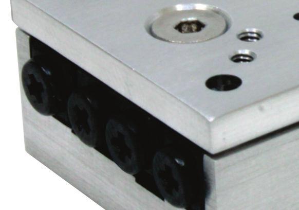
9 4. Installing the PPS-28 All mounting patterns require M2.5 screws for mounting and M1.5 x 5mm dowel pins for precision alignment. Additional brackets and screws may be needed for custom applications. 4.1 PPS-28 Installation General Mounting For general mounting configurations, mount the base to the mounting surface. Align carriage with clearance holes to access base mounting pattern. (Please note, it is possible to move the carriage manually without damaging the stage) Requires: 2x M1.5 x 5mm Dowel Pins 2x M2.5 x 5mm Socket Head Cap Screws (optional) 2x M2 x 5mm Socket Head Cap Screw for ear mounts Clearance Hole Direction of Travel Customer Supplied Base Plate or Mounting Surface 1. Align Carriage with Clearance Hole. Install Dowel Pins and M2 Socket Head Cap Screw 2. Align carriage with remaining clearance hole and install second M2 Socket Head Cap Screw Travel A B 26mm mm mm mm


10 4.1.2 X-Y Mounting For additional mounting configurations see section 8. Stacking Configurations (Please note, it is possible to move the carriage manually without damaging the stage) Travel A B 26mm mm mm mm Requires: 4x M1.5 x 4mm Dowel Pins 4X M2.5 Button Head Screws 2x M2 x 4mm Socket Head Screws Direction of Travel Y-Axis Stage 2. Align X-Axis Stage Carriage with Clearance Holes. Install Dowel Pins and M2 Socket Head Cap Screw 1. Align Carriage with remaining clearance holes and install second M2 Socket Head Cap Screw Note: For stages assembled in an XY configuration in factory do not require disassembly for base mounting 8
11 5. Connecting the PPS Atmospheric Environments For controller information refer to the appropriate MMC controller manual Open Loop Installation & Wiring Diagram Connecting the PPS-28 in an open loop configuration only requires that the D- sub 9 Pin Motor Cable be connected to a compatible controller. No other cables or components are needed Closed Loop/Encoder Installation & Wiring Diagram Using the PPS-28 stage with an encoder requires a closed loop compatible controller (MMC-100 or MMC-110) that recognizes encoder feedback. Connect the stage as shown below Analog Encoder Wiring Diagram 9
12 Digital Encoder Wiring Diagram For a PPS-28 with a digital encoder, connect the stage as shown below using the supplied 15 to 9 pin cable to connect the Encoder Module to the Controller. PPS-28 Shown with 2nm External Encoder 5.2 Vacuum Environments Handling and Preparation When preparing the stage for vacuum environments, take the necessary precautions (such as wearing gloves, clean room clothing, etc.) when handling the stage as to avoid any contaminants. Maximum Bake-out temperature is 100 C. MICRONIX USA supplies the stage with vacuum compatible connectors: 9-pin female PEEK connectors for open loop, 15-Pin female PEEK connector for closed loop with analog encoder, 25-pin female PEEK connector for closed loop with digital encoder Open loop Installation & Wiring Diagram Connecting an open loop PPS-28 in a vacuum chamber requires the use of a feed through connector at the vacuum chamber wall. The vacuum compatible PPS-28 will be supplied with wiring for a straight through feed through not a cross over gender changer. MICRONIX USA supplies test connectors that simulate the vacuum feed through to allow functionality test prior to installation in a vacuum chamber. For details regarding the pin-out and feed through specifications see the Appendix A.3 10
13 5.2.3 Closed Loop/Encoder Installation & Wiring Diagram Closed loop installation of the PPS-28 stage in vacuum environments requires an intermediate feed through connector at the vacuum chamber wall that can accommodate both the motor cable, and the encoder cable. The vacuum compatible PPS-28 will be supplied with wiring for a straight through feed through not a cross over gender bender. MICRONIX USA supplies test connectors that simulate the vacuum feed through to allow functionality test prior to installation in a vacuum chamber. For details regarding the pin-out and feed through specifications see the Appendix A.4.5, A Analog Encoder Wiring Diagram 11
14 Digital Encoder Wiring Diagram 6. Dimensions 6.1 PPS-28 20mm with Digital Encoder. * Grey parts for external closed loop only L Travel A B C 45 26mm mm mm mm


15 6.2 PPS-28 20mm with Analog Encoder L Travel A B C 45 26mm mm mm mm Stacking Configurations 7.1 Configuration Examples (Additional configurations available upon request) X-Y PPS-28, PPS-20 Using Adapter Plate (P/N: ) PPS-28 & PR-32 13
16 8. Supplementary Information 8.1 Maintenance The PPS-28 series of Linear Piezo stages utilizes a maintenance free design. Do not modify the stage or perform any maintenance unless specifically instructed to do so by MICRONIX USA personal. If the stage is not performing up to the original specifications, please contact MICRONIX USA. The PPS-28 Linear Piezo stage is a precision mechanical device and should be handled with care. Do not drop or mishandle the stage. Do not touch the bearings, as this will contaminate the lubrication and jeopardize the longevity of the stage. Follow the Installation Preparation requirements and use proper cable management to ensure a clean and safe operating environment. 8.2 Units and Conventions All measurements in this document are in the metric system of units. Metric Unit English Unit 1 millimeter inches 1 micron inches 1 Newton lbs 1 Newton-meter 8.85 in-lbs 14
17 A. Appendix A.1 DB-9 Male Motor Connector Pin Description Color 1 Phase 1 Red 2 Phase 2 Yellow 3 N/C N/C 4 Not In Use N/C 5 Ground Black& Green 6 +5V N/C 7 +5V N/C 8 Not In Use N/C 9 Not in Use N/C A.2 2 Phase Piezo Motor Wiring Diagram 15
18 A.3 Open Loop Vacuum Wiring Diagram A.3.1 Straight Through 9-Pin Feed Through 16


19 A.4 26BUsing the Digital Encoder Module When using the digital external encoder configuration, the Encoder Module should display two green LED s indicating a power source and proper encoder alignment. A Red or Yellow Signal Level LED indicates misalignment of the Encoder Head, if this occurs contact MICRONIX USA. Do not adjust the Encoder Head or scale. For more information refer to MicroE Systems Mercury Encoders. A BEncoder Module Pin-out Pin Description Pin Description 1 *Right Limit+ 9 Ground 2 Ground 10 *Left Limit+ 3 *Right Limit- 11 *Left Limit- 4 Index- 12 Index+ 5 B- 13 B+ 6 A- 14 A+ 7 +5V 15 (not used) 8 +5V *-Limits must be specified at the time of order, and calibrated at the factory. Note: Tri-state alarm: A and B are tri-stated if the encoder signal becomes too low for reliable operation. 17
20 A.4.2 Operating and Electrical Specifications Power Supply 5VDC 140mA (No outputs 180mA (A, B, I, and both limits terminated); 50mA at the sensor Operating Temperature 0 to 70 C Humidity 10-90% RH non-condensing A.4.3 Output Signals & Signal Termination for A quad B, Index and limits *Output signals are differential. Inverse signals are not shown for clarity. **Note: At some interpolations values the index pulse may be aligned with other states of A or B than the ones shown. ***Above are with reference to the sensor s optical centerline A.4.4 Resolution All closed loop stages are supplied with 20µm scales. The digital encoder module interpolates to a higher resolution as specified in the order. With a digital encoder the MMC-100 has an achievable resolution of 2nm. 18
 C. Encoder Module Breakout Cable (Female Dsub 25 Pin to MII 6000 Interpolator Module, 1m) D.")
21 A.4.5 Digital Encoder Wiring Diagram Cable Descriptions: A. PPS-28 Motor Cable - Vacuum Side (Female Dsub 25 Pin Peek Connector, 1.5m) B. PPS-28 Encoder Cable - Vacuum Side (Female Dsub 25 Pin Peek Connector, 1.5m) C. Encoder Module Breakout Cable (Female Dsub 25 Pin to MII 6000 Interpolator Module, 1m) D. Motor Breakout Cable (Female Dsub 25 Pin to Male Dsub 9 Pin, 1.5m) E. Encoder Module Adapter Cable (Female Dsub 15 Pin to Female Dsub 9 Pin,.5m) Wiring Diagram: A C E D J5 J6 B J1 J2 J3 J4 Description: Color J1 J2 J3 Color J4 J8 Phase 1 Red Red 13 1 Phase 2 Yellow W hite (Green TP) 12 2 Ground Black/Green Black/Green 25 5 Shield Casing + 5VDC Red Red 10 GND Black Black 22 DCLK - Gray Gray 9 DCLK + W hite (Gray TP) W hite (Gray TP) 21 M ISO - Violet Violet 8 M ISO + W hite (Violet TP) W hite (Violet TP) 20 M OSI - Blue Blue 7 M OSI + W hite (Blue TP) W hite (Blue TP) 19 nss - Green Green 6 nss + W hite (Green TP) W hite (Green TP) 18 CLK - Brown Brown 5 CLK + W hite (Brown TP) W hite (Brown TP) 17 Shield NC J8 J Female PEEK Dsub25 Connector - Rear View Description: J5 Color J6 J8 Index - 4 W hite (Purple TP) 4 8 B - 5 W hite (Yellow TP)5 7 A - 6 W hit e (Brow n TP) VDC 7 Red 7 5 Ground 2 Black 2 4 I ndex + 12 Purple 12 3 B + 13 Yellow 13 2 A + 14 Brow n 14 1 A.4.6 Straight Through 25-Pin Feed Through 19
22 A.5 Using an Analog Encoder A.5.1 Analog Encoder Overview A PPS-28 with Analog encoder will need to be paired with an appropriate controller. The MMC-100 has an Analog option. The PPS-28 with internal Analog encoder will be supplied with a 15 pin connector that incorporates both motor and encoder signals. A.5.2 Encoder Pin-out Pin Description 1 A+/Cos+ 2 B+/Sin+ 3 Index + 4 Ground 5 +5V 6 A-/Cos- 7 B-/Sin- 8 Index - 9 Not In Use A.5.3 Operating and Electrical Specifications Power Supply 5VDC 330mA (60mA for sensor) Operating Temperature 0 to 70 C Humidity 10-90% RH non-condensing A.5.4 Analog Output (Pins 1,2,6, and 7) A.5.5 Index Window (Pins 3) 20
23 A.5.6 Resolution All closed loop stages are supplied with 20µm scales. The interpolation is done in the MMC-100 to a higher resolution as specified in the order. With an analog encoder the MMC-100 has an achievable resolution of 10nm. A.5.7 Analog Encoder Wiring Diagram Standard Cable Descriptions: A. PPS-28 Motor Cable - Vacuum Side (Female Dsub 15 Pin Peek Connector, 1.5m) B. PPS-28 Encoder Cable - Vacuum Side (Female Dsub 15 Pin Peek Connector, 1.5m) C. Encoder Cable (Female Dsub 15 Pin to Dsub 9 Pin 1.5m) D. Motor Breakout Cable (Female Dsub 15 Pin to Male Dsub 9 Pin, 1.5m) Wiring Diagram: J6 A C B J1 J2 J3 J4 D J5 Description: Color J1 J2 J3 J4 J5 J6 Phase 1 Red (Red) 1 Phase 2 Yellow (W hite - Green TP) 2 Ground Black/Green (Black/Green) 5 Shield (Shield) Casing GND Black (Black) 4 Cos+ Brown (Brown) 1 +5V Red (Red) 5 Cos- Orange (W hite - Brown TP) 6 Sin+ Yellow (Yellow ) 2 Sin- Green (W hite - Yellow TP) 7 Index- Blue (Violet - W hite TP) 8 Index+ Violet (Violet ) 3 Shield (Shield) Casing Female PEEK Dsub15 Connector - Rear View A.5.8 Straight Through 15-Pin Feed Through 21
Precision Piezo Stage Reference Manual (Open and Closed Loop Versions)
") PPS-20 S e r i e s Precision Piezo Stage (Open and Closed Loop Versions) PPS-20 Piezo Positioner Stage Rev 3.10 MICRONIX USA, LLC 15375 Barranca Parkway, E-106 Irvine, CA 92618 Tel: 949-480-0538 Fax: 949-480-0538
PPS-20 S e r i e s Precision Piezo Stage (Open and Closed Loop Versions) PPS-20 Piezo Positioner Stage Rev 3.10 MICRONIX USA, LLC 15375 Barranca Parkway, E-106 Irvine, CA 92618 Tel: 949-480-0538 Fax: 949-480-0538
PR-32. Piezo Rotation Stage Reference Manual. S e r i e s. (Open and Closed Loop Versions)
") PR-32 S e r i e s Piezo Rotation Stage (Open and Closed Loop Versions) PR-32 Piezo Rotation Stage Rev 3.00 MICRONIX USA, LLC 15375 Barranca Parkway, E-106 Irvine, CA 92618 Tel: 949-480-0538 Fax: 949-480-0538
PR-32 S e r i e s Piezo Rotation Stage (Open and Closed Loop Versions) PR-32 Piezo Rotation Stage Rev 3.00 MICRONIX USA, LLC 15375 Barranca Parkway, E-106 Irvine, CA 92618 Tel: 949-480-0538 Fax: 949-480-0538
Precision Piezo Stage Reference Manual (Open and Closed Loop Versions)
") PPX-32 Series Precision Piezo Stage (Open and Closed Loop Versions) PPX-32 Piezo Positioner Stage Rev 3.02 MICRONIX USA, LLC 15375 Barranca Parkway, E-106 Irvine, CA 92618 Tel: 949-480-0538 Fax: 949-480-0538
PPX-32 Series Precision Piezo Stage (Open and Closed Loop Versions) PPX-32 Piezo Positioner Stage Rev 3.02 MICRONIX USA, LLC 15375 Barranca Parkway, E-106 Irvine, CA 92618 Tel: 949-480-0538 Fax: 949-480-0538
VT-50. Linear Positioning Stage Reference Manual. S e r i e s. (Open and Closed Loop Versions)
") VT-50 S e r i e s Linear Positioning Stage (Open and Closed Loop Versions) VT-50L Linear Stage Rev 1.03 MICRONIX USA, LLC 15375 Barranca Parkway, E-106 Irvine, CA 92618 Tel: 949-480-0538 Fax: 949-480-0538
VT-50 S e r i e s Linear Positioning Stage (Open and Closed Loop Versions) VT-50L Linear Stage Rev 1.03 MICRONIX USA, LLC 15375 Barranca Parkway, E-106 Irvine, CA 92618 Tel: 949-480-0538 Fax: 949-480-0538
Linear Positioning Stage Reference Manual
 PP-30 Series Linear Positioning Stage PP-30 Piezo Positioner Stage Rev 3.00 MICRONIX USA, LLC 15375 Barranca Parkway, E-106 Irvine, CA 92618 Tel: 949-480-0538 Fax: 949-480-0538 Email: info@micronixusa.com
PPS-60. Precision Positioner Stage Reference Manual. S e r i e s. (Open and Closed Loop Versions)
") PPS-60 S e r i e s Precision Positioner Stage (Open and Closed Loop Versions) PPS-60 Precision Positioner Stage Rev 1.04 MICRONIX USA, LLC 15375 Barranca Parkway, E-106 Irvine, CA 92618 Tel: 949-480-0538
PPS-60 S e r i e s Precision Positioner Stage (Open and Closed Loop Versions) PPS-60 Precision Positioner Stage Rev 1.04 MICRONIX USA, LLC 15375 Barranca Parkway, E-106 Irvine, CA 92618 Tel: 949-480-0538
Linear Actuator Reference Manual
 MP-21 S e r i e s Linear Actuator MP-21 Linear Actuator Rev 3.04 MICRONIX USA, LLC 15375 Barranca Parkway, E-106 Irvine, CA 92618 Tel: 949-480-0538 Fax: 949-480-0538 Email: info@micronixusa.com http://micronixusa.com
PXL33 with 25, 60 and 110 mm travel
 Linear Stages with 25, 60 and 110 mm travel Features < 2nm incremental motion possible Resolutions to 10nm and 1Vpp available Small footprint, low profile Travel to 110mm Linear motor Linear encoder Limit
SERIE 59. Rear clamp. Frontal clamp HIGH RESOLUTION HOLLOW SHAFT INCREMENTAL ENCODER FOR INDUSTRIAL APPLICATIONS
 HIGH RESOLUTION HOLLOW SHAFT INCREMENTAL ENCODER FOR INDUSTRIAL APPLICATIONS Resolution up to 50.000 pulses per turn External diameter 58 mm Hollow shaft from Ø 10 to 14 mm Protection class IP67 according
MTE Series Encoders. Performance and Value Compact Linear Encoder. Specifications. Benefits
 Specifications Resolution 5µm, 2.5µm, 1µm Linearity Outputs Tape Scale: ±10µm over 1m A-quad-B, Index Window, Alarm Scale Pitch 20µm Benefits Compact Footprint Miniature sensor Compact tape scale Energy
Performance and Value Optical Encoder System. Specifications. Benefits
 Specifications Resolution Linearity Accuracy Cyclical Error Outputs Linear: 1µm, 0.5µm, 0.1µm, or 50nm Rotary: 163k to 3.27M CPR Tape Scale: ±5µm over 1m Linear Glass Scale: ±3µm over 1m Rotary Glass Scale:
MX80S Ballscrew and Leadscrew Driven Stages
 Miniature MX80S Features MX80S Ballscrew and Leadscrew Driven Stages Features Miniature Size - Low Profile (35 mm high X 80 mm wide) Normal or cleanroom environments 25, 50,, 150 mm travels Multi-axis
MPS50SL Miniature Mechanical-Bearing Screw-Driven Linear Stage
 MPSSL Miniature Mechanical-Bearing Screw-Driven Linear Stage Compact mm width, with travel to mm Precision ground ball-screw or lead-screw drive DC servo or stepper motor Crossed-roller bearings High resolution
PLG160 Linear Stage PLG mm Travel PLG160 s. NEMA23 In-Line. Frameless Motor
 200mm Travel s NEMA23 In-Line Frameless Motor Features Travel to 600mm Loads up to 50kg Precision Ballscrew Drive Integrated Frameless Servo Motor or NEMA23 Motor Mount Internal Linear or Rotary encoder,
SENC 150 REFERENCE MANUAL
 SENC 50 REFERENCE MANUAL SENC 50 Table of Contents / Warnings Page Introduction / Supplied items... 4 2 Preparing the mounting / Mounting information... 5 3 Encoder dimensions... 8 4 Backup spar dimensions...
PCL40. PCL40 Linear Stage. PCL40 with 400 mm travel
 PCL4 Linear Stage PCL4 PCL4 with 4 mm travel Features Travel to 4mm Optional rotary encoder resolution to 1. micron 1 kg payload capacity Two motor options Limit sensors 4mm tall single axis, 8mm tall
LHM-E Product User's Manual Firmware 5.00 and up. Last Update: September Visit for more recent updates.
 LHM-E Product User's Manual Firmware 5.00 and up Last Update: September 15 2017 Visit www.zaber.com/wiki for more recent updates. Zaber Technologies Inc. #2-605 West Kent Ave. N. Vancouver, British Columbia
PLG110 Linear Stage PLG mm Travel PLG110 s. Frameless Motor With Ballscrew Linear Motor
 100mm Travel s Frameless Motor With Ballscrew Linear Motor Features Travel to 600mm Loads up to 25kg Precision Ballscrew Drive or Linear Motor Drive Integrated Frameless Servo Motor or NEMA23 Motor Mount
PLG210 Linear Stage PLG210. XYT stack of PLG160 and PLG210 Frameless Motor Stages on PLR350. XY stack of PLG210x300mm with in-line motor mount
 Linear Stage XYT stack of PLG160 and Frameless Motor Stages on PLR350 XY stack of x300mm with in-line motor mount Features Travel to 600mm Loads up to 100kg Precision Ballscrew Drive Integrated Frameless
RS-232 Industrial Media Converter
 USER GUIDE The leader in rugged fiber optic technology. U-151 2018C-0327 Industrial Media Converter COMPACT, RUGGED & TEMPERATURE HARDENED Introduction This Industrial Serial Data media converter transports
Cutter Option Installation Instructions
 This kit includes the parts and documentation necessary to install the cutter option on the Zebra XiII, XiIII, and XiIIIPlus-Series printers. NOTE: The Cutter Option is not available for the 96XiIII. Adding
MX Voice Gateway Series. Installation Manual
 MX Voice Gateway Series Installation Manual Revision Record Revision version 1.0 (2009-05-07 Author:ZNH) The first revision. Shanghai New Rock Technologies, Inc. Page 2/23 Contents 1 Installation Preparation...
LX80L Linear Motor Tables
 LX80L Series LX80L Linear Motor Tables Features Velocity to 3 m/sec Acceleration to 5 g s Encoder resolution to 0.1 micron Cleanroom compatible Easy multi-axis mounting Internal cable management Introduction
Delivery. Connection. C. AA+BB Helicoidal cable 2. Radial M12 8p CCW. 3. Radial M23 12p CCW
 PROGRAMMABLE INCREMENTAL HOLLOW SHAFT ENCODER FOR INDUSTRIAL APPLICATIONS Programmable incremental optical encoder from 1 to 65.536 pulses per rotation Programmable via USB, without an additional programming
KRAMER ELECTRONICS LTD. USER MANUAL MODELS: WP-110, XGA Line Transmitter. PT-120, XGA Line Receiver. TP-120, XGA Line Receiver. P/N: Rev 1
 KRAMER ELECTRONICS LTD. USER MANUAL MODELS: WP-110, XGA Line Transmitter PT-120, XGA Line Receiver TP-120, XGA Line Receiver P/N: 2900-300180 Rev 1 Contents 1 Introduction 1 2 Getting Started 2 2.1 Achieving
PSW-002. Fiber Optic Polarization Switch. User Guide
 PSW-002 Fiber Optic Polarization Switch User Guide Version: 1.1 Date: June 30, 2015 General Photonics Corporation is located in Chino California. For more information visit the company's website at: www.generalphotonics.com
ACORN User Guide For Revision (Aka Acorn_rev3) Updated 1/23/17
 Updated 1/23/17") ACORN User Guide For Revision 171025 (Aka Acorn_rev3) Updated 1/23/17 Overview ACORN is technically a breakout board for the BeagleBone Green or BeagleBone Black embedded computer. The remainder of this
ACORN User Guide For Revision 171025 (Aka Acorn_rev3) Updated 1/23/17 Overview ACORN is technically a breakout board for the BeagleBone Green or BeagleBone Black embedded computer. The remainder of this
VE-53 Sensor Uniaxial / Triaxial Surface and Downhole Velocity Sensor. Operation Manual
 VE-53 Sensor Uniaxial / Triaxial Surface and Downhole Velocity Sensor Operation Manual Company: Author: Checked: Approved: Level: Distribution: GeoSIG Ltd Wiesenstrasse 39, 8952 Schlieren, Switzerland,
RS-232 Fiber Link Card System
 USER GUIDE The leader in rugged fiber optic technology. U-152 2018B-0406 Fiber Link Card System SYSTEM INSTALLATION INFORMATION Introduction The Fiber Link Card system transports a full 9-Pin copper signal
Product Description. Simplifying Motion Control
 Vacuum compatible to 10-6 Torr 25, 50, 100, 150, 200 mm travel 10 kg load capacity Up to 100 mm/s speed and up to 35 N thrust Built-in controller; daisy-chains with other Zaber products Only 4 feedthrough
Product Information ECI 1118 EQI 1130 ECI 1119 EQI Absolute Rotary Encoders without Integral Bearing
 Product Information ECI EQI 0 ECI 9 EQI Absolute Rotary Encoders without Integral Bearing 0 ECIEQI 00 Absolute rotary encoders Synchro flange 0F) for axial mounting Blind hollow shaft A) Without integral
SDG1400 User s Guide
 SDG1400 User s Guide Model SDG1400 Rate Sensor Systron Donner Inertial Sales and Customer Service Phone: +1 925.979. 4500 Fax: +1 925.349.1366 E-Mail: sales@systron.com www.systron.com SDG1400 User s Guide
MPS75SL. Miniature Mechanical-Bearing Screw-Driven Linear Stage. Compact 75 mm width, with travel to 100 mm. Precision ground ball-screw drive
 MPSSL Miniature Mechanical-Bearing Screw-Driven Linear Stage Compact mm width, with travel to 0 mm Precision ground ball-screw drive DC servo or stepper motor nti-creep crossed-roller bearings High resolution
3-Card Slot, Includes P1/P2/P3/P4 compatibility for Analog I/O, Digital I/O, & Pulse/Frequency
 DBK213 Screw-Terminal & Expansion Card Module 3-Card Slot, Includes P1/P2/P3/P4 compatibility for Analog I/O, Digital I/O, & Pulse/Frequency Overview 1 Connection Tips 2 Installing DBK Cards 3 System Examples
SUM-40 OPERATING MANUAL. Ma0 DYNAMIC STRUCTURES AND MATERIALS, LLC REV
 Ma0 SUM-40 OPERATING MANUAL DYNAMIC STRUCTURES AND MATERIALS, LLC REV. 171011 Please review the following points for both personal and equipment safety while operating the SUM-40 motor. HIGH ENERGY/VOLTAGE
Data Sheet. Model ER position sensor, features a versatile rod-and-cylinder design with optional dual rod ends. Interrogation Return wire.
 Temposonics Magnetostrictive, Absolute, Non-contact Linear-Position Sensors E-Series Model ER Analog / Digital-Pulse (Start/Stop) Output SENSORS Document Part Number 550996 Revision D Data Sheet Model
4.8 Expansion Module MAC00-FS1/FS4
 .8 Expansion Module MAC00-FS/FS MAC00-FS With M connectors MAC00-FS With D sub connectors TT08GB.8. High speed serial RS8 module MAC00-FS and FS Introduction The MAC00-FS and FS are used for high speed
Includes P1/P2/P3/P4 compatibility for Analog I/O, Digital I/O, & Pulse/Frequency
 DBK214 16-Connector BNC Interface Module Includes P1/P2/P3/P4 compatibility for Analog I/O, Digital I/O, & Pulse/Frequency Overview 1 Block Diagram 2 Connection Tips 3 System Examples 4 Using the Screw-Terminal
GV-EL124S Electric Strike
 GV-EL124S Electric Strike Featured with a built-in door status sensor, the GV-EL124S is a fail-secure electric strike, but it is field convertible from fail secure to fail safe. It can be mounted either
CBM-105 Connections. Male Connector on Card WAGO # Male Connector on Card WAGO #
 CN1 2 PIN connector for Power CBM-105 Connections Male Connector on Card WAGO #734-162 Female Connector for Wiring WAGO #734-102 PN:1104417 & 18 PIN Description 1 +24VDC +/-10% (full-wave rectified, smoothed
Incremental Encoder with Hollow Shaft
 Incremental Encoder Type RI 36-H n miniature industry encoder for high number of pulses n short mounting length n easy mounting procedure n Application e.g.: - Motors - Machine tools - Packaging Machines
1500V - Vacuum Rated
 Preliminary 8/20/2008 Mercury Digital Output Encoder System Installation Manual and Reference Guide 1500V - Vacuum Rated Customer Controller Vacuum Wall Manual No. IM-M1500V Rev S7 Introduction MicroE
Stepper Systems. Chapter Four. Features Machine Specifications And Bid Proposals. Catalog Numbers
 Stepper Systems Features Machine Specifications And Bid Proposals Chapter Four Stepper 11x13: Stepper 21x19: Stepper 21x29: Stepper 21x39: Stepper 31x33: Stepper 49x41: Catalog Numbers HX33SBME01201505
Material: Weight: Shaft Loads: Cable: Connector:
 Absolute Encoder Type 2RMHF-SSI Absolute Encoder - Ø 24 mm Blind Hollow Shaft - Ø 3 mm to Ø 1/4 inch Singleturn or Multiturn SSI Interface Binary or Gray Code Preset of Zero Position Choice of Counting
Ultra Low Noise Laser 1550nm
 Ultra Low Noise Laser 1550nm User Manual Version 1.01 Last Updated 07/13/17 www.apichip.com T: 310 642-7975 F: 310 642-7829 Page 1 of 10 Revision Table Revision Description 1.0 Initial release 1.01 Cable
User Manual Version: Date:
 User Manual VT-80 Translation Stage 1 Order no. 6230-9- DC-B-026 1 2Phase-041 2 25 mm (xy mounted at PI micos) 1 50 mm 2 75 mm 3 100 mm 4 150 mm 5 200 mm 6 300 mm 8 VT-80 Translation Stage Order no. 6230-9-
Component identification
 IO-ATC8 I/O Expansion Module 8 Analog/Thermocouple Inputs The IO-ATC8 is an I/O Expansion Module that can be used in conjunction with specific Unitronics OPLC controllers. The module offers 8 inputs that
Features. 400LXR Series Linear Motor Tables. 400LXR Series
 400LXR Series Linear Motor Tables Features Velocity to 4.5 m/sec Acceleration to 5 Gs Encoder resolution to 0.1 micron Cleanroom compatible Easy multi-axis mounting Cable management system Proven strip
GSV-1A4 M12/2 M12/2. Highlights
 GSV-1A4 M12/2 M12/2 Highlights Input sensitivity: 2mV/V; 4mV/V, 2 mv/v, 1mV/V, 0.5mV/V configurable via jumpers Output signals ±10V AND 12mA+-8mA on 15 pin Sub-D Integrated half and quarter bridge completion
9 Maintenance and Repair
 Agilent 1200 Infinity II Series RID User Manual 9 Maintenance and Repair Introduction to Maintenance 120 Warnings and Cautions 121 Overview of Maintenance 123 Cleaning the Module 124 Storage of the Detector
Product Discontinuation Notices. Discontinuation Notice of Safety Laser Scanner Type OS3101 series
 PRODUCT NEWS Product Discontinuation Notices July 4, 2011 Presence Detection Sensors No. 2011195E Discontinuation Notice of Safety Laser Scanner Product Discontinuation Safety laser scanner Accessories
V8-80HS-1 SERIES OF HIGH-SPEED MOTORIZED ZOOM LENSES
 X684 V8-80HS-1 SERIES OF HIGH-SPEED MOTORIZED ZOOM LENSES Copyright 2000 Vicon Industries Inc. All rights reserved. Product specifications subject to change without notice. Vicon and its logo are registered
E2A. Ordering Information. Cylindrical Proximity Sensor. Safe Mounting with Greater Sensing Distance. E2A Cylindrical Proximity Sensor 1
 Cylindrical Proximity Sensor E2A Safe Mounting with Greater Sensing Distance Ensures a sensing distance approximately 1. to 2 times larger than that of any conventional OMRON Sensor. Problems such as the
AC-43 Accelerometer. User Manual
 AC-43 Accelerometer Manual Page 1 AC-43 Accelerometer User Manual Company: Author: Checked: Approved: Distribution: GeoSIG Ltd Wiesenstrasse 39, 8952 Schlieren, Switzerland, Tel: +41 44 810 21 50, Fax:
USER MANUAL. Kramer Electronics, Ltd. Models:
 Kramer Electronics, Ltd. USER MANUAL Models: PT-110, XGA Line Transmitter WP-110, XGA Line Transmitter PT-120, XGA Line Receiver TP-120, XGA Line Receiver Contents Contents 1 Introduction 1 2 Getting Started
Centroid ACORN CNC controller Specification and Use Guide Updated 8/3/17. Overview
 Centroid ACORN CNC controller Specification and Use Guide Updated 8//7 Overview ACORN is technically a CNC control breakout board for the BeagleBone Green or BeagleBone Black embedded computer the Beagle
T E M P O S O N I C S I I I INSTALLATION
 T E M P O S O N I C S I I I INSTALLATION A N A L O G O U T P U T W I R I N G - A N A L O G O U T P U T S 550572 B CONNECTORS RG Connector: Pin No. Wire Color Function 1 Gray Output #1 (Displacement) *
Connecting MicroE Optira Series Encoder to AMC DigiFlex Servo Drive
 TECHNICAL NOTES: INTERFACING WITH DRIVES Connecting MicroE Optira Series Encoder to AMC DigiFlex Servo Drive TN-1304 REV 151214 1 Introduction... 3 2 Required items... 4 2.1 Optira... 4 2.2 Optira Development
ENC 125 T/E REFERENCE MANUAL. Acu-Rite Companies Inc.
 ENC 125 T/E REFERENCE MANUAL Acu-Rite Companies Inc. ENC 125 T/E Page Introduction... 2 Mounting Preparation... 3 Mounting Information... 4 Encoder Dimensions - ENC 125 T (top mount)... 5 Encoder Dimensions
Optira Series Encoders
 NANO MicroE Encoders PRODUCT DATA SHEET Optira Series Encoders Miniature Precision Encoders for the World s Smallest Spaces By combining the patented PurePrecision optical encoder technology from MicroE
SERIES M813XX. PC/AT-COMPATIBLE KEYBOARDS Panel Mount
 ORIGINATOR NAME FRANKLIN TU DATE 4/20/11 7 MORGAN, IRVINE, CA 92618 PHONE: (877) 782-2648 FAX: (949) 297-8703 SERIES M813XX PC/AT-COMPATIBLE KEYBOARDS Panel Mount Laser Engraved Legends on Plastic Keycaps
Plug-in unit extension block One sensor extension block allows four plug-in units to be added. Power cable for sensors. Snap-connector inputs
 1 Sensor Block for SC Quick connection of 16 sensors Set of 16 inputs directly hooked up to PLC Up to 16 sensors can be connected on one main block followed by three extension blocks (or one snapconnector
Removal and Installation8
 8 Screw Types 8-4 Top Cover Assembly 8-5 Left Hand Cover 8-6 Right Hand Cover 8-10 Front Panel Assembly 8-14 Left Rear Cover 8-15 Right Rear Cover 8-16 Extension Cover (60" Model only) 8-17 Media Lever
FVT/FVR20D2I1C4E INSTALLATION AND OPERATION MANUAL
 2-CHANNEL 10-BIT DIGITALLY ENCODED VIDEO + 2 BI-DIRECTIONAL DATA + AIPHONE INTERCOM + 4 CONTACT CLOSURE + 100MB ETHERNET + REDUNDANT POINT-TO-POINT DUAL SFP OPTICAL PORTS The series utilize 10-bit digital
About this Document 2 Symbols and Typographic Conventions... 2 Figures... 2 Downloading Manuals... 2
 N-310 NEXACT OEM Miniature Linear Drive Contents About this Document 2 Symbols and Typographic Conventions... 2 Figures... 2 Downloading Manuals... 2 Safety 4 Intended Use... 4 Safety Precautions... 4
AI-102. IR Illuminator. Installation Guide. Rev IP Surveillance
 AI-102 IR Illuminator Installation Guide Rev. 1.1 IP Surveillance Revision History: Rev. 1.0: Initial release Rev. 1.1: Changed effective IR range and power consumption. AI-102 Tube Type Infrared Illuminator
Kramer Electronics, Ltd. USER MANUAL. Model: TP Channel UXGA/Audio/RS-232 to CAT 5 Transmitter
 Kramer Electronics, Ltd. USER MANUAL Model: TP-185 8 Channel UXGA/Audio/RS-232 to CAT 5 Transmitter Contents Contents 1 Introduction 1 2 Getting Started 1 2.1 Quick Start 2 3 Overview 3 3.1 Shielded Twisted
Absolute Rotary Encoder E6C-N. Ordering Information. Ideal for Stepping Motor Tripping Detection and Position Control of Loaders or Unloaders
 Absolute Rotary Encoder Ideal for Stepping Motor Tripping Detection and Position Control of Loaders or Unloaders No need to reset origin point at power-up IP50 certification Ideal for packaging, plastics,
USER MANUAL. RC-54DL KNET Auxiliary Control Panel MODEL: P/N: Rev 2
 KRAMER ELECTRONICS LTD. USER MANUAL MODEL: RC-54DL KNET Auxiliary Control Panel P/N: 2900-300130 Rev 2 Contents 1 Introduction 1 2 Getting Started 2 2.1 Achieving the Best Performance 2 3 Overview 3 3.1
3-position, AC100/200V controller for RCP2/RCP3 Series. 3 position, AC100V controller for RCA/RCA2/RCL Series. Controller. Power supply.
 / AMECController -position, AC0/00V controller for RCP/RCP Series position, AC0V controller for RCA/RCA/RCL Series /Flat Cylinder -position controller MEC (Mechanical Engineer Control) Feature Rotary Servo
The Butterfly LaserMount also offers all the features you would expect from a modern butterfly laser diode fixture, including:
 Page 2 202/204 Butterfly LaserMount User s Manual Introduction Thank you for choosing the Butterfly LaserMount from Arroyo Instruments. The Butterfly LaserMount is designed for high performance and long
Contents. Part no.: MLC500T Safety light curtain transmitter
 Part no.: 68000307 MLC500T30-750 Safety light curtain transmitter Figure can vary Contents Technical data Suitable receivers Dimensioned drawings Electrical connection Circuit diagrams Operation and display
DPST-NO None 2 channels Auto-reset Inverse (+/-) 24 VAC/VDC 4 G9SB-2002-A 1 channel or 2
 24 VAC/VDC 4 G9SB-2002-A 1 channel or 2") Safety Relay Unit Ultra Slim Safety Relay Unit 17.5 mm wide models available with 2 or 3 poles. 22.5 mm wide 3 pole models also available EN Standards (TÜV approval) DIN-track mounting possible Ordering
Safety Relay Unit Ultra Slim Safety Relay Unit 17.5 mm wide models available with 2 or 3 poles. 22.5 mm wide 3 pole models also available EN Standards (TÜV approval) DIN-track mounting possible Ordering
Kramer Electronics, Ltd.
 Kramer Electronics, Ltd. Preliminary USER MANUAL Model: FC-50 RS-232 Range Extender Contents Contents 1 Introduction 1 2 Getting Started 1 2.1 Quick Start 2 3 Overview 3 3.1 About the Power Connect Feature
Hall-Effect Paddle Joystick
 Hall-Effect Paddle Joystick Robust design for arduous applications Return-to-center or return-to-end options Under-panel depth minimized to 9mm Rated for 5 million cycles Hall-effect sensor technology
Linear Servo Motor Driven
 Linear Servo Motor Driven High Speed, High Precision Tables Positioning systems needed for many of today s high-technology applications must satisfy an ever-increasing demand for high throughput and the
APMC4110 POWERED PMC CARRIER STANDALONE PCI INTERFACE MODULE
 APMC4110 POWERED PMC CARRIER STANDALONE PCI INTERFACE MODULE USER S MANUAL ACROMAG INCORPORATED Tel: (248) 295-0310 30765 South Wixom Road Fax: (248) 624-9234 P.O. BOX 437 Wixom, MI 48393-7037 U.S.A. Copyright
 Model Number: 4212-PK-045Sensor Connections* SHIELD Silver/clear wire DEBRIS MEASURE RED DEBRIS REF BLUE OIL SIGNAL GREEN OIL REF WHITE TEMP ORANGE PROBE GND BLACK Wire 26 AWG PTFE 3G210 screened with
MPS75SLE. Miniature Mechanical-Bearing Screw-Driven Linear Stage with Linear Feedback. Compact stage with travels to 100 mm
 MPSSLE Miniature Mechanical-Bearing Screw-Driven Linear Stage with Linear Feedback Compact stage with travels to 0 mm Low-thermal expansion glass-scale linear encoder Precision-ground ball-screw drive
uservo box instruction manual
 Safety notes uservo box instruction manual Every machine controlled by computer (PC) can be really dangerous for human life and health. Comply with bolow rules and use Your common sense while working with
The sensor fulfills the specifications of the EMC requirements, if the instructions in the manual are followed.
 Assembly Instructions scancontrol 2600/2650/2900/2950 1. Warnings Connect the power supply and the display-/output device in accordance with the safety regulations for electrical equipment. The power supply
V , V PIMag Voice Coil Linear Actuators
 V-275.430, V-275.431 PIMag Voice Coil Linear Actuators Physik Instrumente (PI) GmbH & Co. KG, Auf der Roemerstrasse 1, 76228 Karlsruhe, Germany Contents About this Document 4 Symbols and Typographic Conventions...
Effective range ABS AT505A ABS AT524 AT527
 AT5XX-X Assembly Type ABS AT Series (Slim Spar Type) (Resolution 0.001µm/0.005µm/0.01µm) Features ABS AT500-S Series ABS AT5 5 - - Resolution 7: 0.001μm *only for AT52 5: 0.005μm (20μm/096) : 0.01μm *only
Electromechanical Automation Applications Note
 Electromechanical Automation Applications Note Product: Trilogy coils & Positioners Rev: 1.0 Subject: Wiring and Setup of Trilogy to AriesEPL with ACR9040 or AriesCE This applications note clarifies the
In-Sight 7010C/7200C/7400C
 The following sections list general specifications for the In-Sight vision system. Vision System Specifications Table 3-1: Vision System Specifications Specifications Minimum Firmware Requirement Job/Program
MobileView Junction Box
 Installation Instructions MobileView Junction Box (Catalog Number 2727-MRJB2) English The MobileView Junction Box (2727-MRJB2) integrates the following terminals into the control system: MobileView Guard
MLC 420. MAGNETIC Press Brake ENCODERS OPERATION MANUAL
 MLC 420 MAGNETIC Press Brake ENCODERS NON-CONTACT INTEGRATED BEARING SYSTEM USER SELECTABLE REFERENCE POSITION LEFT OR RIGHT MOUNTING HIGH RESOLUTION FROM 0.005mm HIGH PROTECTİON AGAİNST VIBRATION IP67
TECHNICAL DATASHEET Absolute Motorfeedback Series AD 34
 For brushless servo motors Light duty encoder Unique mounting concept: Save installation time and cost Mounting Depth: 25 mm (ST), 34 mm (MT) Up to 9 Bit ST - resolution + 2 Bit MT - resolution +20 C operating
TOP - 1. Instruction Manual. Version 1.0 Produced in Jan. 2004
 Version 1.0 Produced in Jan. 2004 Instruction Manual LCD monitor IV-08MP Thank you for purchasing the SHARP IV-08MP LCD monitor. Read this introductory instruction manual carefully to thoroughly familiarize
Thank you for choosing the DIL LaserMount from Arroyo Instruments. The DIL LaserMount is designed for high performance and long term use.
 Page 2 212/214 DIL LaserMount User s Manual Introduction Thank you for choosing the DIL LaserMount from Arroyo Instruments. The DIL LaserMount is designed for high performance and long term use. For applications
The SilverNugget is a servo controller/driver for NEMA 34 frame microstep motors.
 Date: 25 July 2008 www.quicksilvercontrols.com SilverNugget N3 M-Grade The SilverNugget is a servo controller/driver for NEMA 34 frame microstep motors. Property of Page 1 of 13 This document is subject
Fingertip Joystick. Single-axis joystick for easy and ergonomic actuation. Use. Variants
 Fingertip Joystick Single-axis joystick for easy and ergonomic actuation JFT + Compact design for simple "on top" installation in control panels + Parallel arrangement in the tightest installation spaces
Revision A 03/31/2017 GRTAvionics.com. Serial Combiner/Expander
 Quad Serial data Combiner/Expander Revision A 03/31/2017 GRTAvionics.com 1 Table of Contents Revision History...3 Description...4 Compatibility...4 Use with Non-Compatible GRT and other systems...4 Serial
VL BPC MINI. A configurable industrial computer platform. Data sheet 2930_en_F. 1 Description. 2 Features
 A configurable industrial computer platform Data sheet 90_en_F Description PHOENIX CONTACT 0-08- Features The VL BPC MINI is an embedded box PC and is part of the Valueline family of industrial computers.
HIGH PERFORMANCE TRANSISTOR INVERTER TRUE TORQUE CONTROL SERIES
 HIGH PERFORMANCE TRANSISTOR INVERTER TRUE TORQUE CONTROL SERIES 12-BIT BINARY OPTION MANUAL January, 1996 Introduction Thank you for purchasing the 12-bit binary option kit for the Toshiba TOSVERT-130
T E M P O S O N I C S I I I INSTALLATION CAUTION! B. CONNECTORS RG Connector. D6 Connector: INTEGRAL CABLE P Integral Cable
 T E M P O S O N I C S I I I INSTALLATION C A N B U S O U T P U T 550573 B W I R I N G - C A N b u s O U T P U T S CONNECTORS RG Connector Pin No. Wire Color Function 1 Gray CAN-L 2 Pink CAN-H 3 Yellow
Power & Communication Cables
 Power & Communication Cables CBLSM-M & CBLSM-X series is the main power and communications cable consisting of a 7W main motor connector split out to a pre-wired RS- DB- connector to plug directly into
Compact Magnetic Non-contact Safety Switches. Model Number Structure
 Compact Non-contact Safety Switches FS-TGR-N@C Coded Non-contact switches are designed to interlock hinge, sliding or removal guard doors. All coded Non-contact switches have a LED for easy diagnosis.
Power Over Fiber USER GUIDE. SYSTEM INSTALLATION INFORMATION Description. The leader in rugged fiber optic technology. RLH Industries, Inc.
 USER GUIDE RLH Industries, Inc. The leader in rugged fiber optic technology. U-145 2018A-0119 Power Over Fiber SYSTEM INSTALLATI INFORMATI Description Our patented Power Over Fiber (PoF) system provides
Mini Photoelectric Sensor
 Mini Photoelectric Sensor High cost-performance Mini Photoelectric Sensor Saves Installation Space and Wiring Effort and Detects Minute Sensing Objects Pin-point beam (1 to 2-mm dia.) makes it possible