PR-32. Piezo Rotation Stage Reference Manual. S e r i e s. (Open and Closed Loop Versions)
|
|
|
- Anastasia Crawford
- 5 years ago
- Views:
Transcription


1 PR-32 S e r i e s Piezo Rotation Stage (Open and Closed Loop Versions)
2 PR-32 Piezo Rotation Stage Rev 3.00 MICRONIX USA, LLC Barranca Parkway, E-106 Irvine, CA Tel: Fax:
3 Contents 1. Introduction Product Description Recommended Controllers Technical Data Load Characteristics Model Configurations PR-32 Order Numbers Preparing to Install the PR Installation Preparation Package Contents Installing the PR PR-32 Installation General Mounting Connecting the PR Atmospheric Environments Open Loop Installation & Wiring Diagram Closed Loop/Encoder Installation & Wiring Diagram Wiring Diagram for Atmospheric System with Analog Encoder Vacuum Environments Handling and Preparation Open loop Installation & Wiring Diagram Closed Loop/Encoder Installation & Wiring Diagram Technical Specifications Dimensions Stacking Configurations Configuration Examples (Additional configurations available upon request) Supplementary Information Units and Conventions Maintenance A. Appendix A.1 DB-9 Male Motor Connector A.2 Phase Piezo Motor Wiring Diagram A.3 Open Loop Vacuum Wiring Diagram A.3.1 Straight Through 9-Pin Feed Through A.4 Using an Analog Encoder A.4.1 Analog Encoder Overview A.4.2 Encoder Pin-Out A.4.3 Operating and Electrical Specifications A.4.4 Analog Output (Pins 1,2,6, and 7) A.4.5 Index Window (Pins 3) A.4.6 Resolution A.4.7 Analog Encoder Wiring Diagram A.4.8 Straight Through 15-Pin Feed Through A.5 Using the Encoder Module A.5.1 Encoder Module Overview A.5.2 Encoder Module Pinout A.5.3 Operating and Electrical Specifications A.5.4 Output Signals A.5.5 Digital Encoder Wiring Diagram


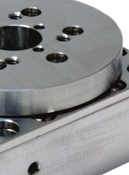
4 1. Introduction 1.1 Product Description The PR-32 is a rotary stage utilizing a dual phase piezo motor for increased precision and load carrying capacity. The use of two mutually pre-loaded steel ball bearings guarantees smooth and stable motion over continuous 360 travel, and an optional angular encoder provides up to 44µ resolution. Vacuum and Ultra High Vacuum (10-9 mbar) compatible versions are available. Features: 360 continuous Load capacity up to 1kg 44µ encoder resolution.5 Aperture Carriage.5 Aperture 2
 Resolution Typical (µ ) Bi-directional Repeatability (µ ) Uni-directional Repeatability (µ ) PM-002R 6 (MMC-100), 30 (MMC-110) 3.")
5 1.2 Recommended Controllers The following controllers are available from MICRONIX USA: MMD-100 MMD-1x1 MMC-100 MMC Technical Data Motor Speed Max. ( /sec) Resolution Typical (µ ) Bi-directional Repeatability (µ ) Uni-directional Repeatability (µ ) PM-002R 6 (MMC-100), 30 (MMC-110) 3.6 (open loop), 44 (encoder resolution) N/A (open loop), ± 220 (with encoder) N/A (open loop), 220(with encoder) 1.4 Load Characteristics Load Characteristics Fx(N) Fy(N) Fz(N) Mx(Nm) Mz(Nm) PM-002R
6 2. Model Configurations 2.1 PR-32 Order Numbers Order No. PR Piezo Motor, PM-002R Continuous 1 Open Loop 0 Analog (1Vpp) 2 No Limit Switch 0 Non-vacuum 0 Vacuum prepared, 10-6 mbar 6 Vacuum prepared, 10-9 mbar 9 Contact MICRONIX USA for custom versions and stacking configurations. 4
7 3. Preparing to Install the PR Installation Preparation When mounting the stage it is important to consider the flatness of the mounting surface, as the stage will conform to the shape of that mounting surface. A surface that is not flat can adversely affect the performance and structural integrity of the stage. The stage is calibrated and guaranteed to be within specification at 20 C ±5 C. Be sure to use the stage under the following conditions: Mount to a clean and flat surface which is free of debris, burrs or dings An indoor atmosphere free of corrosive gasses, and condensation Temperature range of 0-40 C Relative humidity between 20-80% Locate away from water, heat, and electrical noise 3.2 Package Contents If the product is damaged or there are missing components, contact MICRONIX USA immediately. Do not discard product packaging in case of return shipment. Package Should Contain: PR-32 Rotary Stage Any other previously agreed upon components such as a controller 4. Installing the PR-32 All mounting patterns require M2 screws for mounting and M1.5 x 5mm dowel pins for precision alignment. Additional brackets and screws may be needed for custom applications. 5


8 4.1 PR-32 Installation General Mounting For general mounting configurations, mount the base to the mounting surface. Closed Loop System Requires: 2x M1.5 x 5mm Dowel Pins 4x M2 x 25mm Cheese Head Cap Screws Clearance Hole x4 Customer Supplied Base Plate or Mounting Surface 1. Install Dowel Pins and M2 Cheese Head Cap Screw Open Loop System Requires: 2x M1.5 x 5mm Dowel Pins 4x M2 x 12mm Cheese Head Cap Screws 6
9 5. Connecting the PR Atmospheric Environments For controller information refer to the appropriate MMC controller manual Open Loop Installation & Wiring Diagram Connecting the PR-32 in an open loop configuration only requires that the D-sub 9 Pin Motor Cable be connected to a compatible controller. No other cables or components are needed Closed Loop/Encoder Installation & Wiring Diagram Using the PR-32 stage with an encoder requires a closed loop compatible controller that recognizes encoder feedback Wiring Diagram for Atmospheric System with Analog Encoder 7
10 5.2 Vacuum Environments Handling and Preparation When preparing the stage for vacuum environments, take the necessary precautions (wearing latex gloves, clean room clothing, etc.) when handling the stage to avoid any contaminants. Maximum Bake-out temperature 100 C. MICRONIX USA supplies the stage with vacuum compatible connectors: 9-pin female PEEK connector for open loop, 15-Pin female PEEK connector for closed loop Open loop Installation & Wiring Diagram Connecting an open loop PR-32 in a vacuum chamber requires the use of a feed through connector at the vacuum chamber wall. The vacuum compatible PR-32 will be supplied with wiring for a straight through feed through not a cross over gender changer. MICRONIX USA supplies test connectors that simulate the vacuum feed through to allow functionality test prior to installation in a vacuum chamber. For details regarding the pin-out and feed through specifications see the Appendix A Closed Loop/Encoder Installation & Wiring Diagram Closed loop installation of the PR-32 stage in vacuum environments requires the use of a feed through connector at the vacuum chamber wall. The vacuum compatible PR-32 will be supplied with wiring for a straight through feed through not a cross over gender changer. MICRONIX USA supplies test connectors that simulate the vacuum feed through to allow functionality test prior to installation in a vacuum chamber. For details regarding the pin-out and feed through specifications see the Appendix A.4. 8
11 Wiring Diagram for System with Analog Encoder 6. Technical Specifications 6.1 Dimensions 9


12 7. Stacking Configurations 7.1 Configuration Examples (Additional configurations available upon request) PPX-32 & PR-32 Using Adapter Plate (P/N: ) PPS-28 & PR Supplementary Information 8.1 Units and Conventions All measurements in this document are in the metric system of units. Metric Unit English Unit 1 millimeter inches 1 micron inches 1 Newton lbs 1 Newton-meter 8.85 in-lbs 8.2 Maintenance The PR-32 series of rotary stages utilizes a maintenance free design. Do not modify the stage or perform any maintenance unless specifically instructed to do so by MICRONIX USA personal. If the stage is not performing up to the original specifications, please contact MICRONIX USA. The PR-32 rotary stage is a precision mechanical device and should be handled with care. Do not drop or mishandle the stage. Do not touch the bearings, as this will contaminate the lubrication and jeopardize the longevity of the stage. Follow the Installation Preparation requirements and use proper cable management to ensure a clean and safe operating environment. 10
13 A. Appendix A.1 DB-9 Male Motor Connector Pin Description Color 1 Phase 1 Red 2 Phase 2 Yellow 3 N/C N/C 4 Not In Use N/C 5 Ground Black& Green 6 +5V N/C 7 +5V N/C 8 Not In Use N/C 9 Not in Use N/C A.2 Phase Piezo Motor Wiring Diagram 11
14 A.3 Open Loop Vacuum Wiring Diagram A.3.1 Straight Through 9-Pin Feed Through 12
15 A.4 Using an Analog Encoder A.4.1 Analog Encoder Overview A PPS-20 with Analog encoder will need to be paired with an appropriate controller. The MMC-100 has an Analog option. The PPS-20 with an analog encoder will be supplied with a 15 pin connector that incorporates both motor and encoder signals. A.4.2 Encoder Pin-Out Pin Color Description 1 Brown A+/Cos+ 2 Yellow B+/Sin+ 3 Violet Index + 4 Black Ground 5 Red +5V 6 Orange A-/Cos- 7 Green B-/Sin- 8 Blue Index - 9 Not In Use Not In Use A.4.3 Operating and Electrical Specifications Power Supply 5VDC 330mA (60mA for sensor) Operating Temperature 0 to 70 C Humidity 10-90% RH non-condensing A.4.4 Analog Output (Pins 1,2,6, and 7) A.4.5 Index Window (Pins 3) 13
 B. PR-32 Encoder Cable - Vacuum Side (Female Dsub 15 Pin, 1.5m) C. Atmospheric Encoder Cable (Female Dsub 15 Pin to Female Dsub 9 Pin, 1.")
16 A.4.6 Resolution Interpolation done in controller to a higher resolution as specified in the order. With an analog encoder the MMC-100 has an achievable Resolution down to 44μ. A.4.7 Analog Encoder Wiring Diagram Standard Cable Descriptions: A. PR-32 Motor Cable - Vacuum Side (Female Dsub 15 Pin, 1.5m) B. PR-32 Encoder Cable - Vacuum Side (Female Dsub 15 Pin, 1.5m) C. Atmospheric Encoder Cable (Female Dsub 15 Pin to Female Dsub 9 Pin, 1.5m) D. Atmospheric Motor Cable (Female Dsub 15 Pin to Male Dsub 9 Pin, 1.5m) Wiring Diagram: A C D B J1 J2 J3 J4 Description: Color J1 J2 J3 J4 J5 J6 Phase 1 Red (Red) 1 Phase 2 Yellow (W hite - Green TP) 2 Ground Black/Green (Black&Green) 5 Shield (Shield) Casing GND Black (Black) 4 Cos+ Brow n (Brow n) 1 +5V Red (Red) 5 Cos- Orange (W hite - Brow n TP) 6 Sin+ Yellow (Yellow ) 2 Sin- Green (W hite - Yellow TP) 7 Index- Blue (W hite - Violet TP) 8 Index+ Violet (Violet ) 3 Shield (Shield) Casing J5 J Female PEEK Dsub15 Connector - Rear View Female Dsub9 Connector - Rear View Male Dsub9 Connector - Rear View A.4.8 Straight Through 15-Pin Feed Through 14
17 A.5 Using the Encoder Module A.5.1 When connected, the Encoder Module should display two green LED s indicating a power source and proper encoder alignment. A Red or Yellow LED indicates misalignment of the Encoder Head, if this occurs contact MICRONIX USA. Do not manually adjust the Encoder Head or scale. For more information refer to MicroE Systems Mercury Encoders Encoder Module Overview Proper Alignment LED (Green) 15 pin D-sub Connector Improved Alignment LED (Yellow) Improper Alignment LED (Red) Power/Calibration Indicator A.5.2 Encoder Module Pinout Pin Description Pin Description 1 Reserved 9 B- 2 Transmit** 10 B+ 3 Receive** 11 Alarm** 4 A V 5 A+ 13 Ground 6 Reserved 14 Index + 7 Reserved 15 Index - *Note: Proprietary pins reserved for manufacturer programming, not 8 Reserved required to be connected to controller. A.5.3 Operating and Electrical Specifications Power Supply 5VDC 330mA (30mA for sensor) Operating Temperature 0 to 70 C Humidity 10-90% RH non-condensing 15
18 A.5.4 Output Signals *Note: The index pulse may be aligned with A- or B- at some interpolation values. 16
19 A.5.5 Digital Encoder Wiring Diagram Cable Descriptions: A. PR-32 Motor Cable - Vacuum Side (Female Dsub 15 Pin, 1.5m) B. PR-32 Encoder Cable - Vacuum Side (Female Dsub 15 Pin, 1.5m) C. Encoder Module Breakout Cable (Female Dsub 15 Pin to M3500 Interpolator Module, 1m) D. Motor Breakout Cable (Female Dsub 15 Pin to Male Dsub 9 Pin, 2m) E. Encoder Module Adapter Cable (Female HD Dsub 15 Pin to Female Dsub 9 Pin, 1m) Wiring Diagram: A C Mercury 3500 J5 J6 E D B J1 J2 J3 J4 Description: Color J1 J2 J3 J4 J8 Phase 1 Red (Red) 1 Phase 2 Yellow (W hite - Green TP) 2 Ground Black/Green (Black&Green) 5 Shield (Shield) Casing GND Black (Black) Cos+ Brow n (Brow n) +5V Red (Red) Cos- Orange (Orange) Sin+ Yellow (Yellow ) Sin- Green (Green) Index- Blue (Blue) Index+ Violet (Violet ) Shield (Shield) J8 J Female PEEK Dsub15 Connector - Rear View Female Dsub9 Connector - Rear View 17
Precision Piezo Stage Reference Manual (Open and Closed Loop Versions)
") PPX-32 Series Precision Piezo Stage (Open and Closed Loop Versions) PPX-32 Piezo Positioner Stage Rev 3.02 MICRONIX USA, LLC 15375 Barranca Parkway, E-106 Irvine, CA 92618 Tel: 949-480-0538 Fax: 949-480-0538
PPX-32 Series Precision Piezo Stage (Open and Closed Loop Versions) PPX-32 Piezo Positioner Stage Rev 3.02 MICRONIX USA, LLC 15375 Barranca Parkway, E-106 Irvine, CA 92618 Tel: 949-480-0538 Fax: 949-480-0538
PPS-28. Precision Piezo Stage Reference Manual. S e r i e s. (Open and Closed Loop Versions)
") PPS-28 S e r i e s Precision Piezo Stage (Open and Closed Loop Versions) PPS-28 Piezo Positioner Stage Rev 3.02 MICRONIX USA, LLC 15375 Barranca Parkway, E-106 Irvine, CA 92618 Tel: 949-480-0538 Fax: 949-480-0538
PPS-28 S e r i e s Precision Piezo Stage (Open and Closed Loop Versions) PPS-28 Piezo Positioner Stage Rev 3.02 MICRONIX USA, LLC 15375 Barranca Parkway, E-106 Irvine, CA 92618 Tel: 949-480-0538 Fax: 949-480-0538
Linear Positioning Stage Reference Manual
 PP-30 Series Linear Positioning Stage PP-30 Piezo Positioner Stage Rev 3.00 MICRONIX USA, LLC 15375 Barranca Parkway, E-106 Irvine, CA 92618 Tel: 949-480-0538 Fax: 949-480-0538 Email: info@micronixusa.com
VT-50. Linear Positioning Stage Reference Manual. S e r i e s. (Open and Closed Loop Versions)
") VT-50 S e r i e s Linear Positioning Stage (Open and Closed Loop Versions) VT-50L Linear Stage Rev 1.03 MICRONIX USA, LLC 15375 Barranca Parkway, E-106 Irvine, CA 92618 Tel: 949-480-0538 Fax: 949-480-0538
VT-50 S e r i e s Linear Positioning Stage (Open and Closed Loop Versions) VT-50L Linear Stage Rev 1.03 MICRONIX USA, LLC 15375 Barranca Parkway, E-106 Irvine, CA 92618 Tel: 949-480-0538 Fax: 949-480-0538
Precision Piezo Stage Reference Manual (Open and Closed Loop Versions)
") PPS-20 S e r i e s Precision Piezo Stage (Open and Closed Loop Versions) PPS-20 Piezo Positioner Stage Rev 3.10 MICRONIX USA, LLC 15375 Barranca Parkway, E-106 Irvine, CA 92618 Tel: 949-480-0538 Fax: 949-480-0538
PPS-20 S e r i e s Precision Piezo Stage (Open and Closed Loop Versions) PPS-20 Piezo Positioner Stage Rev 3.10 MICRONIX USA, LLC 15375 Barranca Parkway, E-106 Irvine, CA 92618 Tel: 949-480-0538 Fax: 949-480-0538
Linear Actuator Reference Manual
 MP-21 S e r i e s Linear Actuator MP-21 Linear Actuator Rev 3.04 MICRONIX USA, LLC 15375 Barranca Parkway, E-106 Irvine, CA 92618 Tel: 949-480-0538 Fax: 949-480-0538 Email: info@micronixusa.com http://micronixusa.com
PPS-60. Precision Positioner Stage Reference Manual. S e r i e s. (Open and Closed Loop Versions)
") PPS-60 S e r i e s Precision Positioner Stage (Open and Closed Loop Versions) PPS-60 Precision Positioner Stage Rev 1.04 MICRONIX USA, LLC 15375 Barranca Parkway, E-106 Irvine, CA 92618 Tel: 949-480-0538
PPS-60 S e r i e s Precision Positioner Stage (Open and Closed Loop Versions) PPS-60 Precision Positioner Stage Rev 1.04 MICRONIX USA, LLC 15375 Barranca Parkway, E-106 Irvine, CA 92618 Tel: 949-480-0538
SERIE 59. Rear clamp. Frontal clamp HIGH RESOLUTION HOLLOW SHAFT INCREMENTAL ENCODER FOR INDUSTRIAL APPLICATIONS
 HIGH RESOLUTION HOLLOW SHAFT INCREMENTAL ENCODER FOR INDUSTRIAL APPLICATIONS Resolution up to 50.000 pulses per turn External diameter 58 mm Hollow shaft from Ø 10 to 14 mm Protection class IP67 according
KRAMER ELECTRONICS LTD. USER MANUAL MODELS: WP-110, XGA Line Transmitter. PT-120, XGA Line Receiver. TP-120, XGA Line Receiver. P/N: Rev 1
 KRAMER ELECTRONICS LTD. USER MANUAL MODELS: WP-110, XGA Line Transmitter PT-120, XGA Line Receiver TP-120, XGA Line Receiver P/N: 2900-300180 Rev 1 Contents 1 Introduction 1 2 Getting Started 2 2.1 Achieving
ACORN User Guide For Revision (Aka Acorn_rev3) Updated 1/23/17
 Updated 1/23/17") ACORN User Guide For Revision 171025 (Aka Acorn_rev3) Updated 1/23/17 Overview ACORN is technically a breakout board for the BeagleBone Green or BeagleBone Black embedded computer. The remainder of this
ACORN User Guide For Revision 171025 (Aka Acorn_rev3) Updated 1/23/17 Overview ACORN is technically a breakout board for the BeagleBone Green or BeagleBone Black embedded computer. The remainder of this
RS-232 Industrial Media Converter
 USER GUIDE The leader in rugged fiber optic technology. U-151 2018C-0327 Industrial Media Converter COMPACT, RUGGED & TEMPERATURE HARDENED Introduction This Industrial Serial Data media converter transports
LHM-E Product User's Manual Firmware 5.00 and up. Last Update: September Visit for more recent updates.
 LHM-E Product User's Manual Firmware 5.00 and up Last Update: September 15 2017 Visit www.zaber.com/wiki for more recent updates. Zaber Technologies Inc. #2-605 West Kent Ave. N. Vancouver, British Columbia
USER MANUAL. Kramer Electronics, Ltd. Models:
 Kramer Electronics, Ltd. USER MANUAL Models: PT-110, XGA Line Transmitter WP-110, XGA Line Transmitter PT-120, XGA Line Receiver TP-120, XGA Line Receiver Contents Contents 1 Introduction 1 2 Getting Started
SUM-40 OPERATING MANUAL. Ma0 DYNAMIC STRUCTURES AND MATERIALS, LLC REV
 Ma0 SUM-40 OPERATING MANUAL DYNAMIC STRUCTURES AND MATERIALS, LLC REV. 171011 Please review the following points for both personal and equipment safety while operating the SUM-40 motor. HIGH ENERGY/VOLTAGE
The SilverNugget is a servo controller/driver for NEMA 34 frame microstep motors.
 Date: 25 July 2008 www.quicksilvercontrols.com SilverNugget N3 M-Grade The SilverNugget is a servo controller/driver for NEMA 34 frame microstep motors. Property of Page 1 of 13 This document is subject
Performance and Value Optical Encoder System. Specifications. Benefits
 Specifications Resolution Linearity Accuracy Cyclical Error Outputs Linear: 1µm, 0.5µm, 0.1µm, or 50nm Rotary: 163k to 3.27M CPR Tape Scale: ±5µm over 1m Linear Glass Scale: ±3µm over 1m Rotary Glass Scale:
1500V - Vacuum Rated
 Preliminary 8/20/2008 Mercury Digital Output Encoder System Installation Manual and Reference Guide 1500V - Vacuum Rated Customer Controller Vacuum Wall Manual No. IM-M1500V Rev S7 Introduction MicroE
MX Voice Gateway Series. Installation Manual
 MX Voice Gateway Series Installation Manual Revision Record Revision version 1.0 (2009-05-07 Author:ZNH) The first revision. Shanghai New Rock Technologies, Inc. Page 2/23 Contents 1 Installation Preparation...
The SilverNugget is a servo controller/driver for NEMA 17 & 23 frame microstep motors.
 Date: 5 November 2008 www.quicksilvercontrols.com SilverNugget N2 M-Grade The SilverNugget is a servo controller/driver for NEMA 17 & 23 frame microstep motors. Property of Page 1 of 13 This document is
MPS50SL Miniature Mechanical-Bearing Screw-Driven Linear Stage
 MPSSL Miniature Mechanical-Bearing Screw-Driven Linear Stage Compact mm width, with travel to mm Precision ground ball-screw or lead-screw drive DC servo or stepper motor Crossed-roller bearings High resolution
SENC 150 REFERENCE MANUAL
 SENC 50 REFERENCE MANUAL SENC 50 Table of Contents / Warnings Page Introduction / Supplied items... 4 2 Preparing the mounting / Mounting information... 5 3 Encoder dimensions... 8 4 Backup spar dimensions...
RS-232 Fiber Link Card System
 USER GUIDE The leader in rugged fiber optic technology. U-152 2018B-0406 Fiber Link Card System SYSTEM INSTALLATION INFORMATION Introduction The Fiber Link Card system transports a full 9-Pin copper signal
E2A. Ordering Information. Cylindrical Proximity Sensor. Safe Mounting with Greater Sensing Distance. E2A Cylindrical Proximity Sensor 1
 Cylindrical Proximity Sensor E2A Safe Mounting with Greater Sensing Distance Ensures a sensing distance approximately 1. to 2 times larger than that of any conventional OMRON Sensor. Problems such as the
PSW-002. Fiber Optic Polarization Switch. User Guide
 PSW-002 Fiber Optic Polarization Switch User Guide Version: 1.1 Date: June 30, 2015 General Photonics Corporation is located in Chino California. For more information visit the company's website at: www.generalphotonics.com
Centroid ACORN CNC controller Specification and Use Guide Updated 8/3/17. Overview
 Centroid ACORN CNC controller Specification and Use Guide Updated 8//7 Overview ACORN is technically a CNC control breakout board for the BeagleBone Green or BeagleBone Black embedded computer the Beagle
PXL33 with 25, 60 and 110 mm travel
 Linear Stages with 25, 60 and 110 mm travel Features < 2nm incremental motion possible Resolutions to 10nm and 1Vpp available Small footprint, low profile Travel to 110mm Linear motor Linear encoder Limit
CBM-105 Connections. Male Connector on Card WAGO # Male Connector on Card WAGO #
 CN1 2 PIN connector for Power CBM-105 Connections Male Connector on Card WAGO #734-162 Female Connector for Wiring WAGO #734-102 PN:1104417 & 18 PIN Description 1 +24VDC +/-10% (full-wave rectified, smoothed
USER MANUAL. RC-54DL KNET Auxiliary Control Panel MODEL: P/N: Rev 2
 KRAMER ELECTRONICS LTD. USER MANUAL MODEL: RC-54DL KNET Auxiliary Control Panel P/N: 2900-300130 Rev 2 Contents 1 Introduction 1 2 Getting Started 2 2.1 Achieving the Best Performance 2 3 Overview 3 3.1
Incremental Encoder with Hollow Shaft
 Incremental Encoder Type RI 36-H n miniature industry encoder for high number of pulses n short mounting length n easy mounting procedure n Application e.g.: - Motors - Machine tools - Packaging Machines
PLG110 Linear Stage PLG mm Travel PLG110 s. Frameless Motor With Ballscrew Linear Motor
 100mm Travel s Frameless Motor With Ballscrew Linear Motor Features Travel to 600mm Loads up to 25kg Precision Ballscrew Drive or Linear Motor Drive Integrated Frameless Servo Motor or NEMA23 Motor Mount
Product Information ECI 1118 EQI 1130 ECI 1119 EQI Absolute Rotary Encoders without Integral Bearing
 Product Information ECI EQI 0 ECI 9 EQI Absolute Rotary Encoders without Integral Bearing 0 ECIEQI 00 Absolute rotary encoders Synchro flange 0F) for axial mounting Blind hollow shaft A) Without integral
ivu TG Gen2 Image Sensor with Integrated Display
 Datasheet The ivu image sensor is used to monitor parts for type, size, orientation, shape, and location. The ivu TG Gen2 Image Sensor package consists of lighting, sensor, lens, and display. Appropriate
SDG1400 User s Guide
 SDG1400 User s Guide Model SDG1400 Rate Sensor Systron Donner Inertial Sales and Customer Service Phone: +1 925.979. 4500 Fax: +1 925.349.1366 E-Mail: sales@systron.com www.systron.com SDG1400 User s Guide
Can eliminate static charge over an extensive range
 No.BK-P3 Static Electricity Removing Unit Ionizer Wide Area Fan Type Overhead Fan Type Can eliminate static charge over an extensive range Wide area fan type RoHS compliant product Overhead fan type Static
Includes P1/P2/P3/P4 compatibility for Analog I/O, Digital I/O, & Pulse/Frequency
 DBK214 16-Connector BNC Interface Module Includes P1/P2/P3/P4 compatibility for Analog I/O, Digital I/O, & Pulse/Frequency Overview 1 Block Diagram 2 Connection Tips 3 System Examples 4 Using the Screw-Terminal
PCL40. PCL40 Linear Stage. PCL40 with 400 mm travel
 PCL4 Linear Stage PCL4 PCL4 with 4 mm travel Features Travel to 4mm Optional rotary encoder resolution to 1. micron 1 kg payload capacity Two motor options Limit sensors 4mm tall single axis, 8mm tall
Installation Sensing distance Connection Output configuration Operation mode NO Operation mode NC
 Standard (thin shape) Inductive Proximity Sensor Thin shape for space saving surface mounting Direct side wall mounting for bracket-less installation Ordering Information DC 3-wire Models Installation
Kramer Electronics, Ltd.
 Kramer Electronics, Ltd. Preliminary USER MANUAL Model: FC-50 RS-232 Range Extender Contents Contents 1 Introduction 1 2 Getting Started 1 2.1 Quick Start 2 3 Overview 3 3.1 About the Power Connect Feature
Precision Actuators. // West // East
 Precision Actuators www.pimicos.com // info@pi-usa.us // 58.832.3456 East 949.679.9191 West // www.pi-usa.us 4.14 Micro Actuator MA-35 FACTS from the drive. Compared to other Fx(N) Fy(N) Fz(N) DC-B-13
MTE Series Encoders. Performance and Value Compact Linear Encoder. Specifications. Benefits
 Specifications Resolution 5µm, 2.5µm, 1µm Linearity Outputs Tape Scale: ±10µm over 1m A-quad-B, Index Window, Alarm Scale Pitch 20µm Benefits Compact Footprint Miniature sensor Compact tape scale Energy
PLG160 Linear Stage PLG mm Travel PLG160 s. NEMA23 In-Line. Frameless Motor
 200mm Travel s NEMA23 In-Line Frameless Motor Features Travel to 600mm Loads up to 50kg Precision Ballscrew Drive Integrated Frameless Servo Motor or NEMA23 Motor Mount Internal Linear or Rotary encoder,
VE-53 Sensor Uniaxial / Triaxial Surface and Downhole Velocity Sensor. Operation Manual
 VE-53 Sensor Uniaxial / Triaxial Surface and Downhole Velocity Sensor Operation Manual Company: Author: Checked: Approved: Level: Distribution: GeoSIG Ltd Wiesenstrasse 39, 8952 Schlieren, Switzerland,
uservo box instruction manual
 Safety notes uservo box instruction manual Every machine controlled by computer (PC) can be really dangerous for human life and health. Comply with bolow rules and use Your common sense while working with
3-Card Slot, Includes P1/P2/P3/P4 compatibility for Analog I/O, Digital I/O, & Pulse/Frequency
 DBK213 Screw-Terminal & Expansion Card Module 3-Card Slot, Includes P1/P2/P3/P4 compatibility for Analog I/O, Digital I/O, & Pulse/Frequency Overview 1 Connection Tips 2 Installing DBK Cards 3 System Examples
Delivery. Connection. C. AA+BB Helicoidal cable 2. Radial M12 8p CCW. 3. Radial M23 12p CCW
 PROGRAMMABLE INCREMENTAL HOLLOW SHAFT ENCODER FOR INDUSTRIAL APPLICATIONS Programmable incremental optical encoder from 1 to 65.536 pulses per rotation Programmable via USB, without an additional programming
Mechanically Activated Device for Dry Run Protection in Applications with LORENTZ Solar Pump Systems
 Well Probe Mechanically Activated Device for Dry Run Protection in Applications with LORENTZ Solar Pump Systems The switch can be used to detect the water level within a well. When the water level in the
Product Discontinuation Notices. Discontinuation Notice of Safety Laser Scanner Type OS3101 series
 PRODUCT NEWS Product Discontinuation Notices July 4, 2011 Presence Detection Sensors No. 2011195E Discontinuation Notice of Safety Laser Scanner Product Discontinuation Safety laser scanner Accessories
-C5RS-LC RS232 EXTENDER
 XTENDEX Series ST-C5RS-LC RS232 EXTENDER Installation and Operation Manual ST-C5RS-LC RS232 Extender Man249 Rev. 10/30/17 TRADEMARK XTENDEX is a registered trademark of Network Technologies Inc in the
Kramer Electronics, Ltd. USER MANUAL. Model: TP Channel UXGA/Audio/RS-232 to CAT 5 Transmitter
 Kramer Electronics, Ltd. USER MANUAL Model: TP-185 8 Channel UXGA/Audio/RS-232 to CAT 5 Transmitter Contents Contents 1 Introduction 1 2 Getting Started 1 2.1 Quick Start 2 3 Overview 3 3.1 Shielded Twisted
PLG210 Linear Stage PLG210. XYT stack of PLG160 and PLG210 Frameless Motor Stages on PLR350. XY stack of PLG210x300mm with in-line motor mount
 Linear Stage XYT stack of PLG160 and Frameless Motor Stages on PLR350 XY stack of x300mm with in-line motor mount Features Travel to 600mm Loads up to 100kg Precision Ballscrew Drive Integrated Frameless
MobileView Junction Box
 Installation Instructions MobileView Junction Box (Catalog Number 2727-MRJB2) English The MobileView Junction Box (2727-MRJB2) integrates the following terminals into the control system: MobileView Guard
USER MANUAL. RC-74DL Master Room Controller MODEL: P/N: Rev 4
 KRAMER ELECTRONICS LTD. USER MANUAL MODEL: RC-74DL Master Room Controller P/N: 2900-000691 Rev 4 Contents 1 Introduction 1 2 Getting Started 2 2.1 Achieving the Best Performance 2 2.2 Safety Instructions
User Manual Version: Date:
 User Manual VT-80 Translation Stage 1 Order no. 6230-9- DC-B-026 1 2Phase-041 2 25 mm (xy mounted at PI micos) 1 50 mm 2 75 mm 3 100 mm 4 150 mm 5 200 mm 6 300 mm 8 VT-80 Translation Stage Order no. 6230-9-
Kramer Electronics, Ltd. USER MANUAL. Models: TP-125, UXGA / Audio / Data Line Transmitter TP-126, UXGA / Audio / Data Line Receiver
 Kramer Electronics, Ltd. USER MANUAL Models: TP-125, UXGA / Audio / Data Line Transmitter TP-126, UXGA / Audio / Data Line Receiver Contents Contents 1 Introduction 1 2 Getting Started 1 2.1 Quick Start
Beam Position Monitor For High Energy Particle Beams
 Beam Position Monitor For High Energy Particle Beams Features 16 by 16 strip ionization chamber sensor High vacuum compatible Small insertion length (152.4 mm) Robust thin steel foil vacuum windows Very
Driver/Controller Development Assistance Package For IDEX Health & Science TitanHT TM Driver Board
 Driver/Controller Development Assistance Package For IDEX Health & Science TitanHT TM Driver Board Page 1 of 19 Table of Contents Proprietary Letter... 3 Introduction... 4 Section 1.0 Driver Specifications
The Butterfly LaserMount also offers all the features you would expect from a modern butterfly laser diode fixture, including:
 Page 2 202/204 Butterfly LaserMount User s Manual Introduction Thank you for choosing the Butterfly LaserMount from Arroyo Instruments. The Butterfly LaserMount is designed for high performance and long
V8-80HS-1 SERIES OF HIGH-SPEED MOTORIZED ZOOM LENSES
 X684 V8-80HS-1 SERIES OF HIGH-SPEED MOTORIZED ZOOM LENSES Copyright 2000 Vicon Industries Inc. All rights reserved. Product specifications subject to change without notice. Vicon and its logo are registered
GV-EL124S Electric Strike
 GV-EL124S Electric Strike Featured with a built-in door status sensor, the GV-EL124S is a fail-secure electric strike, but it is field convertible from fail secure to fail safe. It can be mounted either
E4PA. Ultrasonic Displacement Sensor. Ordering Information
 Ultrasonic Displacement Sensor Ideal for controlling liquid level. Long sensing distance and high-resolution analog output. High-precision detection with a wide range of measurements Four types of Sensors
2 Channel POTS DIN Fiber Link System
 USER GUIDE The leader in rugged fiber optic technology. U-8 07A-040 Channel POTS DIN Fiber Link System SYSTEM INSTALLATION INFORMATION The RLH Channel Plain Old Telephone Service (POTS) DIN Fiber Link
Material: Weight: Shaft Loads: Cable: Connector:
 Absolute Encoder Type 2RMHF-SSI Absolute Encoder - Ø 24 mm Blind Hollow Shaft - Ø 3 mm to Ø 1/4 inch Singleturn or Multiturn SSI Interface Binary or Gray Code Preset of Zero Position Choice of Counting
Thread length. 27 (40) mm. 27 (44) mm. 27 (40) mm. 34 (50) mm. 34 (49) mm. 39 (60) mm. 39 (54) mm. 44 (65) mm. 44 (59) mm
 mm. 27 (44) mm. 27 (40) mm. 34 (50) mm. 34 (49) mm. 39 (60) mm. 39 (54) mm. 44 (65) mm. 44 (59) mm") Long Distance Cylindrical. Extra long for increased protection and sensing performance triple proximity sensors for flush mounting requirements. designed and tested for extra long life. Ordering Information
Long Distance Cylindrical. Extra long for increased protection and sensing performance triple proximity sensors for flush mounting requirements. designed and tested for extra long life. Ordering Information
4.8 Expansion Module MAC00-FS1/FS4
 .8 Expansion Module MAC00-FS/FS MAC00-FS With M connectors MAC00-FS With D sub connectors TT08GB.8. High speed serial RS8 module MAC00-FS and FS Introduction The MAC00-FS and FS are used for high speed
USER MANUAL. RC-76R/RC-78R Room Controllers MODEL: P/N: Rev 2
 KRAMER ELECTRONICS LTD. USER MANUAL MODEL: RC-76R/RC-78R Room Controllers P/N: 2900-300253 Rev 2 Contents 1 Introduction 1 2 Getting Started 2 2.1 Achieving the Best Performance 2 2.2 Safety Instructions
NRG 200M Wind Vane Authors:
 NRG 200M Wind Vane Authors: Technical Services CONTENTS INTRODUCTION... 3 SENSOR IDENTIFICATION... 3 POWER REQUIREMENTS... 3 MOUNTING... 4 Install the sensor onto mounting boom:... 4 Note about new NRG
Component identification
 IO-ATC8 I/O Expansion Module 8 Analog/Thermocouple Inputs The IO-ATC8 is an I/O Expansion Module that can be used in conjunction with specific Unitronics OPLC controllers. The module offers 8 inputs that
VM 6.1. Capacitive Air Gap Measuring Chains User s Manual P/N: M7A-110
 VM 6.1 Capacitive Air Gap Measuring Chains User s Manual P/N: 9428-25M7A-110 Safety Information The following manual contains information and warnings. They must be followed in order to keep the instrument
Stepper Systems. Chapter Four. Features Machine Specifications And Bid Proposals. Catalog Numbers
 Stepper Systems Features Machine Specifications And Bid Proposals Chapter Four Stepper 11x13: Stepper 21x19: Stepper 21x29: Stepper 21x39: Stepper 31x33: Stepper 49x41: Catalog Numbers HX33SBME01201505
Cutter Option Installation Instructions
 This kit includes the parts and documentation necessary to install the cutter option on the Zebra XiII, XiIII, and XiIIIPlus-Series printers. NOTE: The Cutter Option is not available for the 96XiIII. Adding
USER MANUAL. TP-145 XGA/Audio/Data Line Transmitter. TP-146 UXGA/Audio/Data Line Receiver MODELS: P/N: Rev 3
 KRAMER ELECTRONICS LTD. USER MANUAL MODELS: TP-145 XGA/Audio/Data Line Transmitter TP-146 UXGA/Audio/Data Line Receiver P/N: 2900-000607 Rev 3 Contents 1 Introduction 1 2 Getting Started 2 2.1 Achieving
Absolute Rotary Encoder E6C-N. Ordering Information. Ideal for Stepping Motor Tripping Detection and Position Control of Loaders or Unloaders
 Absolute Rotary Encoder Ideal for Stepping Motor Tripping Detection and Position Control of Loaders or Unloaders No need to reset origin point at power-up IP50 certification Ideal for packaging, plastics,
USER MANUAL. 621T DVI Optical Transmitter. 621R DVI Optical Receiver MODEL: P/N: Rev 8
 KRAMER ELECTRONICS LTD. USER MANUAL MODEL: 621T DVI Optical Transmitter 621R DVI Optical Receiver P/N: 2900-000103 Rev 8 Contents 1 Introduction 1 2 Getting Started 2 2.1 Achieving the Best Performance
USER S MANUAL VER.2. C76- MULTIFUNCTION CNC BOARD Rev. 1.4
 USER S MANUAL VER.2 C76- MULTIFUNCTION CNC BOARD Rev. 1.4 MARCH 2018 User s Manual Page i USER'S MANUAL TABLE OF CONTENTS Contents Page # 1.0 FEATURES... 1 2.0 I/O SPECIFICATIONS... 2 3.0 BOARD DESCRIPTION...
MX80S Ballscrew and Leadscrew Driven Stages
 Miniature MX80S Features MX80S Ballscrew and Leadscrew Driven Stages Features Miniature Size - Low Profile (35 mm high X 80 mm wide) Normal or cleanroom environments 25, 50,, 150 mm travels Multi-axis
UR51 Industrial Cellular Router
 UR51 Industrial Cellular Router Quick Start Guide 1 Ursalink Technology Co., Ltd. Welcome Thank you for choosing Ursalink UR51 industrial cellular router. This guide describes how to install the UR51 and
Thread length (overall length) material
 material") Cylindrical Proximity Sensor for Mobile Usage Designed and tested to keep your machines moving IP69k tested and certified for highest water resistance e1 type approval (according to automotive directive
Cylindrical Proximity Sensor for Mobile Usage Designed and tested to keep your machines moving IP69k tested and certified for highest water resistance e1 type approval (according to automotive directive
Data Sheet. Model ER position sensor, features a versatile rod-and-cylinder design with optional dual rod ends. Interrogation Return wire.
 Temposonics Magnetostrictive, Absolute, Non-contact Linear-Position Sensors E-Series Model ER Analog / Digital-Pulse (Start/Stop) Output SENSORS Document Part Number 550996 Revision D Data Sheet Model
9 Maintenance and Repair
 Agilent 1200 Infinity II Series RID User Manual 9 Maintenance and Repair Introduction to Maintenance 120 Warnings and Cautions 121 Overview of Maintenance 123 Cleaning the Module 124 Storage of the Detector
HMT330 Series Humidity and Temperature Transmitters for Industrial Applications
 HMT330 Series Humidity and Temperature Transmitters for Industrial Applications The HMT330 transmitter family has the solution for demanding industrial humidity measurements. Six models for demanding industrial
KRAMER ELECTRONICS LTD. USER MANUAL MODEL: RC-74DL Master Room Controller. P/N: Rev 5
 KRAMER ELECTRONICS LTD. USER MANUAL MODEL: RC-74DL Master Room Controller P/N: 2900-000691 Rev 5 Contents 1 Introduction 1 2 Getting Started 2 2.1 Achieving the Best Performance 2 2.2 Safety Instructions
MDrive Linear Actuator
 MDrive Linear Actuator Compact, integrated all-in-one linear motion systems Hybrid Linear Actuator, Description MDrive Hybrid Linear Actuator MDrive Hybrid Linear Actuator,, non-captive and external shaft
2 Channel POTS with I/O DIN Fiber Link System
 USER GUIDE The leader in rugged fiber optic technology. U-9 07A-040 Channel POTS with DIN Fiber Link System SYSTEM INSTALLATION INFORMATION The RLH Channel Plain Old Telephone Service (POTS) DIN Fiber
KRAMER ELECTRONICS LTD. USER MANUAL MODEL: RC-76R/RC-78R Room Controllers. P/N: Rev 5
 KRAMER ELECTRONICS LTD. USER MANUAL MODEL: RC-76R/RC-78R Room Controllers P/N: 2900-300253 Rev 5 Contents 1 Introduction 1 2 Getting Started 2 2.1 Achieving the Best Performance 2 2.2 Safety Instructions
Thank you for choosing the DIL LaserMount from Arroyo Instruments. The DIL LaserMount is designed for high performance and long term use.
 Page 2 212/214 DIL LaserMount User s Manual Introduction Thank you for choosing the DIL LaserMount from Arroyo Instruments. The DIL LaserMount is designed for high performance and long term use. For applications
Kramer Electronics, Ltd. USER MANUAL. Model: WP-209. Wall Plate
 Kramer Electronics, Ltd. USER MANUAL Model: WP-209 Wall Plate Contents Contents 1 Introduction 1 2 Getting Started 1 2.1 Quick Start 1 3 Overview 3 4 Your WP-209 4.1 Your WP-209 Front Panel 4 4 4.2 Your
AC-43 Accelerometer. User Manual
 AC-43 Accelerometer Manual Page 1 AC-43 Accelerometer User Manual Company: Author: Checked: Approved: Distribution: GeoSIG Ltd Wiesenstrasse 39, 8952 Schlieren, Switzerland, Tel: +41 44 810 21 50, Fax:
The Model 464-BC Monitor controls and stores flow data from Marsh- McBirney Flo-Dar sensors. A portable computer and Flo-Ware software is used to
 Chapter 5 Model 464-BC Monitor Operation The Model 464-BC Monitor controls and stores flow data from Marsh- McBirney Flo-Dar sensors. A portable computer and Flo-Ware software is used to setup the flowmeter
Revision A 03/31/2017 GRTAvionics.com. Serial Combiner/Expander
 Quad Serial data Combiner/Expander Revision A 03/31/2017 GRTAvionics.com 1 Table of Contents Revision History...3 Description...4 Compatibility...4 Use with Non-Compatible GRT and other systems...4 Serial
KRAMER ELECTRONICS LTD. USER MANUAL MODEL: 622T Dual Link DVI Optical Transmitter. 622R Dual Link DVI Optical Receiver. P/N: Rev 4
 KRAMER ELECTRONICS LTD. USER MANUAL MODEL: 622T Dual Link DVI Optical Transmitter 622R Dual Link DVI Optical Receiver P/N: 2900-000104 Rev 4 Contents 1 Introduction 1 2 Getting Started 2 2.1 Achieving
Lexium MDrive. LMD P57 Pulse / direction input REACH IP65. Product overview. General features. Intelligent motion systems
 LMD P57 Pulse / direction input REACH IP65 Product overview Robust Pulse /Direction products integrate 1.8 2-phase stepper motors with onboard control electronics and hmt closed loop performance. Products
KOBOLD TDA Series Digital Temperature Transmitter
 KOBOLD TDA Series Digital Temperature Transmitter TDA-15 Series User Instructions KOBOLD Instruments Inc. 1801 Parkway View Drive Pittsburgh, PA 15205 Phone (412) 788-2830 Fax (412)-788-4890 www.koboldusa.com
T E M P O S O N I C S I I I INSTALLATION
 T E M P O S O N I C S I I I INSTALLATION A N A L O G O U T P U T W I R I N G - A N A L O G O U T P U T S 550572 B CONNECTORS RG Connector: Pin No. Wire Color Function 1 Gray Output #1 (Displacement) *
CHAPTER 1. Introduction Introduction 3
 Technical & User Manual Weight Indicator: SMIT-3015 Manufactured By: Samyak Instrumentation Pvt.Ltd. F-4, Memnagar Complex, Opp.Petrol Pump, Memnagar Village, Ahmedabad, India-380052. Phone: +91-79-27495500/5600,
VL BPC MINI. A configurable industrial computer platform. Data sheet 2930_en_F. 1 Description. 2 Features
 A configurable industrial computer platform Data sheet 90_en_F Description PHOENIX CONTACT 0-08- Features The VL BPC MINI is an embedded box PC and is part of the Valueline family of industrial computers.
General Purpose ph/orp Sensor
 Instruction Sheet PN 51A-399VP/rev.J January 2011 Model 399VP General Purpose ph/orp Sensor SPECIFICATIONS Sensor Type: General purpose 399VP Measured Range: ph: ACCUGLASS 0-14 ORP: -1500 to +1500 mv Percent
MODEL: R1M-P4. PC Recorders R1M Series. SPECIFICATIONS OF OPTION: Q COATING (For the detail, refer to M-System's web site.)
") PC Recorders Series PC RECORDER (4 totalized counter inputs, 8 contact inputs and outputs) Functions & Features Industrial recorder on PC Totalized counter inputs Counts stored in E 2 PROM Easy system
PC Recorders Series PC RECORDER (4 totalized counter inputs, 8 contact inputs and outputs) Functions & Features Industrial recorder on PC Totalized counter inputs Counts stored in E 2 PROM Easy system
OPERATOR S MANUAL VM-4100
 TABLE OF CONTENTS OPERATOR S MANUAL The Daugherty Companies, Inc. P.O. Box 306 Warren, IN 46792 Ph. 260-375-2415 - Fax 260-375-3800 www.ag-electronics.com Planter Monitor NOTES: 2 INTRODUCTION System Overview
Mini Photoelectric Sensor
 Mini Photoelectric Sensor High cost-performance Mini Photoelectric Sensor Saves Installation Space and Wiring Effort and Detects Minute Sensing Objects Pin-point beam (1 to 2-mm dia.) makes it possible
EF-S1 SERIES. Continuously check invisible static electricity in lines. Constantly check static in lines!
 1215 PHOTO PHOTO SAFETY USE SERIES Related Information General terms and conditions... F- General precautions... P.1595 guide... P.1155~ MEASUREMENT panasonic.net/id/pidsx/global Continuously check invisible