OS 4.1 AND AUTOMAP UNIVERSAL 2.0
|
|
|
- Magnus Wright
- 6 years ago
- Views:
Transcription

1 OS 4.1 AND AUTOMAP UNIVERSAL 2.0 Rev-02
2 ReMOTE SL USER GUIDE FOR ReMOTE SL OS 4.1 AND AUTOMAP UNIVERSAL 2.0 CONTENTS 1 INTRO 2 REGISTRATION 3 HARDWARE OVERVIEW 3.1 FRONT PANEL OVERVIEW 3.2 REAR PANEL CONNECTIONS AND OTHER FEATURES 4 GETTING STARTED WITH THE REMOTE SL 4.1 POWERING THE REMOTE SL 4.2 INSTALLATION - PC 4.3 INSTALLATION - MAC 4.4 CONNECTING THE REMOTE SL 4.5 USING THE REMOTE SL AS A MIDI INTERFACE 4.6 MODES AND MENUS OVERVIEW 4.7 TEMPLATES 5 AUTOMAP OVERVIEW 5.1 AUTOMAP UNIVERSAL 5.2 SEQUENCER AUTOMAP 5.3 AUTOMAP AND THE REMOTE SL S MIDI PORTS 5.4 AUTOMAP TEMPLATES AND STANDARD TEMPLATES WHAT IS THE DIFFERENCE? 5.5 RECORDING PARAMETER AUTOMATION WHEN USING AUTOMAP 6 AUTOMAP UNIVERSAL 6.1 AUTOMAP UNIVERSAL TERMINOLOGY 6.2 THE AUTOMAP SERVER 6.3 THE AUTOMAP SETTINGS 6.4 THE PLUG-IN MANAGER 7 CONTROLLING PLUG-INS WITH AUTOMAP UNIVERSAL 7.1 AUTOMAP-WRAPPED PLUG-INS 7.2 THE AUTOMAP UNIVERSAL TEMPLATE 7.3 THE AUTOMAP UNIVERSAL WINDOW 7.4 CONTROL MAP OPTIONS 7.5 PLUG-IN PARAMETER LAYOUT 7.6 DEFAULT AND INSTANCE CONTROL MAPS 7.7 EDITING A CONTROL MAP 7.8 CONTROL SETTINGS NAME, RANGE AND STEP SIZE 7.9 SAVING A CONTROL MAP
3 8 CONTROLLING A SEQUENCER MIXER WITH AUTOMAP UNIVERSAL 8.1 CUBASE/NUENDO SETUP 8.2 SONAR SETUP 8.3 TRACKTION SETUP 9 THE AUTOMAP MIDI CLIENT 9.1 MIDI PORTS 9.2 MIDI CONTROL MAPS 9.3 ASSIGNING MIDI MESSAGES 9.4 USING LEARN MODE TO ASSIGN MIDI MESSAGES 9.5 SAVING A MIDI CONTROL MAP 10 SEQUENCER AUTOMAP 10.1 LOGIC 10.2 ABLETON LIVE 10.3 PRO TOOLS 10.4 DIGITAL PERFORMER 10.5 REASON 10.6 VJAMM 11 THE GLOBAL MENU 11.1 SAVING GLOBAL SETTINGS 12 STANDARD TEMPLATES 13 PLAY MODE 13.1 THE DATA/SELECT ENCODER 14 EDIT MODE 14.1 CONTROL CHANGE (CC) 14.2 NON-REGISTERED PARAMETER NUMBER (NRPN) 14.3 REGISTERED PARAMETER NUMBER (RPN) 14.4 SYSTEM EXCLUSIVE (SYSEX) 14.5 MIDI MACHINE CONTROL (MMC) 14.6 NOTE ON/OFF (NOTE) 14.7 PROGRAM CHANGE (PROG CHG) 14.8 BANK CHANGE (BANK CHG) 14.9 DRUM PAD NOTE (DRUMNOTE) TEMPLATE SYSTEM REAL TIME (REALTIME) PITCH BEND (PITCHBND) 15 THE TEMPLATE MENU 16 KEYBOARD ZONES
4 17 SAVING AND NAMING TEMPLATES 17.1 RESTORING TEMPLATES APPENDIX I SPECIFICATIONS II LIST OF FACTORY TEMPLATES III GUIDE TO FACTORY STANDARD TEMPLATES IV STANDARD SYNTH PARAMETER LAYOUT FOR FACTORY STANDARD TEMPLATES
5 1 INTRO Welcome to the Novation ReMOTE SL User Guide! This guide is designed to help you get started with the controller, as well as to provide comprehensive information about its operational features and Automap software. The content is structured in a way that should allow you to read only as far as you need to. Basic and essential information is covered early on whilst the latter sections deal with more advanced features. We are constantly developing the ReMOTE SL and Automap Universal, and software updates will be made available as free downloads on the Novation website. We suggest checking the ReMOTE SL product page regularly to ensure you have the latest update and documentation. No troubleshooting section has been included in this guide. If you require further guidance or technical support after reading this guide, please visit the Novation Answerbase, which can be found in the support area at com. The Novation Answerbase contains troubleshooting articles for all Novation products and a technical support contact form that you can use to get in touch with us if you cannot find the information you are after. 2 REGISTRATION To register your ReMOTE SL, visit and click the Register link in the main menu at the top of the home page, then fill in the required details. Once you have registered, your one-year product warranty will become active, providing a no compromise service solution. In addition to this you can sign up to receive Novation e-zines, which are newsletters (sent once every two or three months) containing product update news, competitions, freebies and tips from signed artists. Registering your ReMOTE SL is the best way to ensure you are aware of updates, and receive help with any technical enquires you may make.

6 3 HARDWARE OVERVIEW 3.1 FRONT PANEL OVERVIEW Assignable controls - Numbers 1-8: These are controls that can be assigned to parameters of the software or hardware you are controlling detented endless rotary encoders 2. 8 pots mm sliders buttons 5. 8 velocity-sensitive drum pads 6. 6 transport buttons 7. Pitch/mod joystick 8. X-Y touchpad System controls - Numbers 9-14: These controls are not assignable. They have fixed functions. 9. SCROLL buttons: Use these to scroll through pages of options when in a menu or through pages of additional control info when in Play mode. These buttons have other functions when using Automap (see sections 7 to 10 for further info). 10. ROW-SELECT buttons: Use these to select which row of controls has its info shown on the display. These buttons can have other functions when using Automap (see sections 7 to 10 for further info). 11. Mode/Menu buttons (WRITE, TEMPLATE, EDIT, GLOBAL and PLAY): Use these to access the different modes and menus of the ReMOTE SL. 12. TAP TEMPO button: Press this repeatedly to set the tempo. 13. OCTAVE UP/DOWN buttons: Use these to transpose the keyboard up/down in octave steps. 14. DATA/SELECT encoder: Use this to select templates, send bank or program change messages or set the tempo. Press the encoder to change its current function, indicated by the LEDs to the right of it.
 to be connected for powering the ReMOTE SL from a mains supply.")


7 3.2 REAR PANEL CONNECTIONS AND OTHER FEATURES PSU Connector: This allows a power supply unit (not supplied with the ReMOTE SL) to be connected for powering the ReMOTE SL from a mains supply. Power select switch: This sets the power supply between Battery/DC, Off and USB. USB connector: This allows the ReMOTE SL to be connected to a computer using the supplied USB cable. The USB connection provides power as well as data flow. Sustain pedal input: This allows connection of a damper-style sustain pedal or footswitch to the ReMOTE SL. Expression pedal input: This allows connection of an expression pedal to the ReMOTE SL. 5-pin DIN MIDI Connectors: These allow the ReMOTE SL to be connected to other hardware MIDI devices. Four connectors are provided in total one IN, one THRU and two OUT connectors. Battery Compartment: Found on the bottom of the unit, this compartment holds four 1.5V IEC R14 (C size) batteries for powering the ReMOTE SL. Pitch/Mod Joystick Spring Selector: Found on the bottom of the ReMOTE SL, this slider selects whether the pitch/mod joystick springs to the bottom or moves freely in the vertical (mod) direction. Slide it towards the back of the ReMOTE SL to enable the spring or towards the front for free movement. The raised end (opposite the slider) must be gently pushed in before the slider is moved backwards or forwards.

 batteries into the battery compartment of the ReMOTE SL and set the power select switch to Battery/Ext DC. 4.")

8 4 GETTING STARTED WITH THE REMOTE SL 4.1 POWERING THE REMOTE SL The ReMOTE SL can be powered in one of three ways: USB: Connect the ReMOTE SL to a computer using the supplied USB cable and set the power select switch to USB. PSU: Connect a mains PSU to the ReMOTE SL and set the power select switch to Battery/Ext DC. The required PSU output specs are 9V, mA d.c., centre pin positive. Battery: Insert four 1.5V IEC R14 (C size) batteries into the battery compartment of the ReMOTE SL and set the power select switch to Battery/Ext DC. 4.2 INSTALLATION - PC The latest ReMOTE SL installer is compatible with Windows XP SP2, XP X64 and Vista (32 and 64 bit editions) Connect the ReMOTE SL to your computer via USB and ensure it is switched on. If the Windows Found New Hardware Wizard opens, click Cancel to close it. If you already have an older version of Automap Universal installed, make sure the Automap Server is NOT running. Double-click on ReMOTESLSetup.exe to run the installer. Whilst the driver is installing, the following message may appear: Win XP Win Vista Click Continue Anyway (Win XP) or Install (Win Vista) to continue installation. 4. Once the driver is installed, you will be prompted to select whether you have a keyboard version of the ReMOTE SL or a ReMOTE SL ZeRO. The installer will then guide you through updating your ReMOTE SL with on-screen instructions. Please read and follow these instructions carefully to ensure the unit gets updated correctly.


9 5. Towards the end of installation, the Automap Plug-in Manager will open automatically. Select the plug-ins you want to use with Automap by dragging them from the left-hand list to the right-hand list, then click OK to close the Plug-in Manager window and complete the installation. 4.3 INSTALLATION - MAC The latest ReMOTE SL installer is compatible with OS X or later Connect the ReMOTE SL to your computer via USB and ensure it is switched on. If you already have an older version of Automap Universal installed, make sure the Automap Server is NOT running. Mount ReMOTESLInstaller.dmg and double click on Setup ReMOTE SL to run the installer.


: The Sysex Upgrade application will guide you through updating your ReMOTE SL with on-screen instructions.")
10 3. During installation, the Automap Plug-in Manager will open automatically. Select the plug-ins you want to use with Automap by dragging them from the left-hand list to the right-hand list, then click OK to close the Plug-in Manager window. 4. The ReMOTE SL Sysex Upgrade application will also run automatically and prompt you to select whether you have a keyboard version of the ReMOTE SL or a ReMOTE SL ZeRO (watch out - this window may open behind the Plug-in Manager and Installer windows!): The Sysex Upgrade application will guide you through updating your ReMOTE SL with on-screen instructions. Please read and follow these instructions carefully to ensure the unit gets updated correctly. 4.4 CONNECTING THE REMOTE SL If you want to control software using the ReMOTE SL, connect it to your computer using the supplied USB cable: 10
11 If you want to control hardware MIDI devices using the ReMOTE SL, connect them to the MIDI OUT ports on the back of the unit: Sound Module 1 Midi cable Midi In Midi Out 1 It is possible to use the ReMOTE SL to control hardware MIDI devices in this way without it being connected to a computer. However, if there is no USB connection, the ReMOTE SL must be powered using batteries or a PSU. 4.5 USING THE REMOTE SL AS A MIDI INTERFACE As well as being able to control software and hardware, the ReMOTE SL can be used as a MIDI interface, i.e. it can route MIDI data between your computer and hardware MIDI devices. For this, the ReMOTE SL must be connected to your computer via USB and to your hardware MIDI devices via the MIDI connectors on the back of the unit: USB cable Midi cable Midi In Sound Module 1 USB port Midi Out 1 Midi In Midi Out Computer The ReMOTE SL has two physical MIDI ports. Port 1 has IN, OUT and THRU connectors and port 2 has an OUT connector only. These ports are labelled as M1 and M2 in the menus on the ReMOTE SL where you set how MIDI data is routed in, out or through the unit. The ReMOTE SL has a further three virtual ports over the USB connection. These ports are labelled as U1, U2 and U3 in the menus on the ReMOTE SL where you set how MIDI data is routed in, out or through the unit. Because there are three virtual USB ports, the ReMOTE SL will appear three times in the MIDI input and output device lists in your software as follows: ReMOTE SL Port 1 ReMOTE SL Port 2 ReMOTE SL Port 3 11
12 If you use Windows Vista, the ReMOTE SL will appear as: Input: ReMOTE SL MIDIIN2 (ReMOTE SL) MIDIIN3 (ReMOTE SL) Output: ReMOTE SL MIDIOUT2 (ReMOTE SL) MIDIOUT3 (ReMOTE SL) The Global menu on the ReMOTE SL contains options that allow you to set which ports incoming MIDI data is routed to (see section 11 for further info). The following diagram shows how data can be routed through the ReMOTE SL between the physical MIDI and virtual USB ports: Midi Out 2 Midi Out 1 Midi In In Out USB Port 1 In Out USB Port 2 Reserved for Automap Universal In Out USB Port 3 12
, general template settings (TEMPLATE) and the overall keyboard settings (GLOBAL).")
13 4.6 MODES AND MENUS OVERVIEW The WRITE, TEMPLATE, EDIT, GLOBAL and PLAY buttons in the centre of the ReMOTE SL are the mode and menu buttons. They allow access to settings that affect individual controls within a template (EDIT), general template settings (TEMPLATE) and the overall keyboard settings (GLOBAL). Whilst accessing any of the menus, the left-hand display will show the available settings. The encoder, pot and buttons aligned with each setting on the left-hand side of the ReMOTE SL can be used to edit the settings as follows: Use the SCROLL buttons to scroll through all pages of available settings when accessing a menu. Play Mode: This is the default mode for the ReMOTE SL and the one that will be active when it powers up. In this mode you can use the ReMOTE SL to control software and hardware MIDI devices. The ReMOTE SL can be put into Play mode at any time by pressing the PLAY mode button. Template Menu: This menu allows access to settings that affect the currently selected template. Press the TEMPLATE menu button to access this menu and then use the SCROLL buttons to scroll between the two pages of settings. Pressing the TEMPLATE menu button a second time will access the Template Keyboard Zones menu, where the keyboard can be split into zones for playing different instruments from different areas of the keyboard (see section 16 for further info). Subsequent presses of the TEMPLATE menu button will switch between the Template menu and Template Keyboard Zones menu. Edit Mode: This mode allows access to the individual settings for any assignable control within the currently selected template. Controls that can be edited in this mode are encoders, pots, sliders, buttons, drum pads, transport controls, sustain pedal, expression pedal, pitch/mod joystick and the X-Y touchpad. To access the settings for a control, press and hold the EDIT mode button and operate the control whose settings you want to edit, then release the EDIT mode button. Use the SCROLL buttons to scroll through the pages of settings for the currently selected control (where available). Global Menu: This menu allows access to the general device settings on the ReMOTE SL such as memory protect and joystick calibration. Press the GLOBAL menu button to access the Global menu and use the SCROLL buttons to scroll through the seven pages of global settings. Pressing the GLOBAL menu button a second time will access the Global Keyboard Zones menu, where the keyboard can be split into zones for playing different instruments from different areas of the keyboard (see section 16 for further info). Subsequent presses of the GLOBAL menu button will switch between the Global Menu and Global Keyboard Zones menu. Write Button: The WRITE button allows you to save settings on the ReMOTE SL. Whilst in Play, Edit or Template modes, pressing WRITE will save all changes to the currently selected template (see section 17 for further info on saving templates). Whilst in the Global menu, pressing WRITE saves all global settings. 13
14 4.7 TEMPLATES All the settings for every individual control accessed in Edit mode and the settings accessed in the Template menu can be saved to the ReMOTE SL s internal memory and recalled at any time. A group of saved settings is called a template. As an example of using templates, you may have two synths (software or hardware) that you want to control from the ReMOTE SL. You can set the ReMOTE SL up to control one of the synths and save all the settings as a template. Then you can set the ReMOTE SL up to control the other synth and save the settings as a separate template. Now to switch between controlling the two synths from the ReMOTE SL, you can simply switch between the separate templates you have created for them. There is space for 40 templates on the ReMOTE SL. Templates 1-33 are pre-programmed standard templates, designed to work with popular software instruments. Templates are blank user templates and templates 34, are Automap templates (see section 5.4 for more info on Automap templates). You cannot delete templates so that there are less than 40 stored on the ReMOTE SL, however you can overwrite any template by re-saving one that is already stored on the unit or by uploading one from your computer. There are three ways to switch between the 40 templates: DATA/SELECT Encoder: Ensure that the DATA/SELECT encoder is set to template (press the encoder to change its current function) and then rotate it to select different templates. Quick-Jump: Press and hold the PLAY mode button and then press the TEMPLATE button to use Quick-Jump to select a different template. The names of 16 templates will appear on the left-hand ReMOTE SL display. The upper left-hand row of buttons on the ReMOTE SL can be pressed to jump to one of the 8 templates shown on the top line of the display and the lower left-hand row of buttons can be pressed to jump to one of the 8 templates shown on the bottom line of the display. Templates always appear on the bottom line of the display so that the Automap templates are always available to jump to. Use the SCROLL buttons whilst in Quick-Jump mode to switch the top line between templates 1-8, 9-16, and Use Any Assignable Button or Drum Pad: It is possible to set any assignable button (this excludes the ROW-SELECT, SCROLL, OCTAVE and mode/menu buttons) or drum pad to switch to a different template. See section 14 for further info on how to do this. When you switch to a different template, the name and number of the template will appear briefly on the ReMOTE SL displays before they switch to showing control names and values. To see the name and number of the currently selected template, you can press and hold the PLAY mode button at any time - the number and name of the currently selected template will show for as long as the button is held down. The ReMOTE SL will start up on template 1 by default from the factory. To change the start up template, select the template you want the unit to load on start up, then press the GLOBAL menu button to access the Global menu and press the WRITE button to save the global settings. 14
15 5 AUTOMAP OVERVIEW Automap is a revolutionary system for controlling software plug-ins and sequencers using the ReMOTE SL. Certain templates on the ReMOTE SL are reserved for use with Automap. These are templates 34 and To avoid problems when using Automap, we suggest that, unless instructed, you do not edit these templates. Automap works in two different ways, Automap Universal and Sequencer Automap. 5.1 AUTOMAP UNIVERSAL Automap Universal is a pioneering system that allows automatic mapping of software parameters to the ReMOTE SL. It also provides a quick and simple learn system which you can use to create your own custom control maps. Automap Universal can be used to control any VST, AU or Pro Tools (RTAS or TDM) format plug-in in any sequencer (note Pro Tools plug-in format support is only currently available on Mac). It can also be used to control the mixer in Cubase, Nuendo, Sonar and Tracktion. It is also possible to control software or hardware MIDI devices with Automap Universal using the Automap MIDI client. To use Automap Universal you must select the Automap Universal template (template 38) on the ReMOTE SL and run the Automap Server software on your computer. The Automap Server handles communication between the ReMOTE SL and the software you are controlling. When you run the Server, the Automap Universal window will appear. This is a resizable, semi-transparent, heads-up display from which you can view and edit control assignments, select a different client to control and view the interactive help. To control a plug-in you must first enable it for Automap control in the Plug-in Manager. Once enabled, it will be wrapped, meaning that a new version of the plug-in will be created which is contained within the Automap software. The new Automap-wrapped plug-in will appear in your sequencer with (Automap) after its original name. Load the Automapwrapped plug-in in your sequencer to allow Automap control over it. The plug-in will look exactly the same as before but with the addition of an Automap border at the bottom of the window, from which you can access Automap functions. When you load an Automap-wrapped plug-in, the plug-in parameters will be automatically mapped to the ReMOTE SL controls. You can open as many Automap-wrapped plug-ins as you like (up to a limit of 253) but you can only control one at a time from the ReMOTE SL. To select a plug-in for control, click on the Automap logo in the bottom-left hand corner of the plug-in window so that it turns red. To control the mixer in Cubase, Nuendo, Sonar or Tracktion, first follow the relevant set up instructions in section SEQUENCER AUTOMAP There are separate Automap templates on the ReMOTE SL to allow control over sequencers that do not use Automap Universal for mixer control. These are Pro Tools (template 34), Reason (template 37), Logic (template 39), Ableton Live (template 40) and Digital Performer (installed as template 34 instead of Pro Tools if selected during installation). These work differently to Automap Universal in that the ReMOTE SL communicates directly with the sequencer when using these templates, rather than through the Automap Server software. Each sequencer has its own set up procedure, detailed in section 10 of this guide. Once the set up procedure is complete, the ReMOTE SL will automatically switch to the relevant template each time you open your sequencer. You are free to switch from this template to any other on the unit (to control other software or hardware) and back again. This includes the Automap Universal template for when you want to control Automap-wrapped plug-ins. If you select a Sequencer Automap template for a program which is not running on your computer, you will see an OFFLINE message appear on the ReMOTE SL displays. The Pro Tools, Logic and Ableton Live Sequencer Automap templates include some means for controlling plug-ins. This can be used where it is not possible to use Automap Universal for plug-in control i.e. for those that use a proprietary plug-in format, or where you find it easier than using Automap Universal. 15
16 5.3 AUTOMAP AND THE REMOTE SL S MIDI PORTS The ReMOTE SL has three virtual MIDI ports over the USB connection. USB ports 2 and 3 are used for transfer of Automap data between the ReMOTE SL and the computer. Port 2 is used for transferring Automap data between a sequencer program and the ReMOTE SL (i.e. Sequencer Automap). Port 3 is used for transferring Automap data between the Automap Server software and the ReMOTE SL. If you are using Automap, it is important to only select port 2 or 3 in your software where instructed in this guide. USB Port 1 is used for transfer of all non-automap data between the ReMOTE SL and your computer. This includes keyboard note and aftertouch, pitch bend, modulation, expression and sustain pedals, and program/bank change data. All factory standard (non-automap) templates send data on USB Port 1 too. Ensure only ReMOTE SL Port 1 is selected as the input to MIDI tracks in your sequencer. When controlling plug-ins using Automap Universal, it is important to remember that the keyboard, joystick and pedal inputs on the ReMOTE SL will NOT follow the currently selected Automap-wrapped plug-in. They will always send data to whichever MIDI track is record enabled in your sequencer, meaning you can simultaneously play a soft-synth from the keyboard and use the controls to tweak the parameters of a different plug-in. If you select an Automap-wrapped instrument plug-in for control then you must also record enable the corresponding MIDI or instrument track in your sequencer before the keyboard, joystick and pedals will control it. 5.4 AUTOMAP TEMPLATES AND STANDARD TEMPLATES WHAT IS THE DIFFERENCE? Templates 1-33, 35 & 36 on the ReMOTE SL are standard templates, so called because when they are selected the ReMOTE SL functions as a standard MIDI controller. A standard MIDI controller allows you to set what MIDI message each of its controls sends. If you want to control software or hardware that responds to MIDI then you need to know what messages it responds to. This information can usually be found in the documentation for the software or hardware. Once you know this, you can set up the controls on a standard MIDI controller to send those messages. We have used this method to program the standard templates on the ReMOTE SL to work with popular software instruments (except templates 35 and 36, which are blank user standard templates). These templates can be used where it is not possible or desirable to use Automap Universal for controlling software instruments, for example when using a software instrument as a stand-alone program rather than a plug-in within a sequencer. With standard templates there is only one-way communication from the ReMOTE SL to the software or hardware you are controlling and the ReMOTE SL has no way of knowing when a parameter is changed from the software or hardware itself. For example, if you change a parameter on a software instrument with the mouse, the parameter value displayed on the ReMOTE SL will not update to reflect that change. The Automap templates have been set up such that the controls send MIDI messages that are recognised by the Automap software i.e. the Automap Server or Sequencer Automap implementation. The Automap software then automatically maps those MIDI messages to different plug-in or sequencer parameters, depending on what you select to control. Because Automap incorporates two-way communication between your computer and the ReMOTE SL, the Automap software can send display data back to the ReMOTE SL to automatically name the controls and let you know which parameter each control is currently assigned to. Additionally you can see the current value of each parameter, even if it is being changed using the mouse. 5.5 RECORDING PARAMETER AUTOMATION WHEN USING AUTOMAP To record control movements from the ReMOTE SL in a sequencer when using a standard template, you must record enable a MIDI track and then put the sequencer into record. MIDI control data will then be recorded onto the MIDI track when you operate a control on the ReMOTE SL. When using an Automap template, MIDI control data is converted into Automation data by the Automap software i.e. the Automap Universal Server or Sequencer Automap implementation, to allow control over software parameters. This means that control movements will not be recorded as MIDI data. 16
17 To record control movements from the ReMOTE SL in a sequencer when using an Automap template, you must set the Automation mode on the relevant instrument or audio track to write (some sequencers have a number of different write modes) and then put the sequencer into playback (not record). Automation data will then be written when you operate a control on the ReMOTE SL. Remember to set the Automation mode for the track back to read when you have finished recording control movements. Note that some sequencers use different methods for writing Automation data compared with this so check the documentation for your sequencer. 17
18 6 AUTOMAP UNIVERSAL 6.1 AUTOMAP UNIVERSAL TERMINOLOGY Before you start to use Automap Universal we recommend getting to know the terminology associated with it: Clients Client is the term used for anything you can control using Automap Universal. This could be one of the following: Automap-wrapped plug-in (VST, AU or Pro Tools format) Sequencer mixer Automap MIDI Client Clients connect to the Automap Server and tell it what parameters they have available to control. The Server assigns these parameters to controls on the ReMOTE SL. A maximum number of 253 clients can be connected to the Server at one time. At present only Cubase, Nuendo, Sonar and Tracktion support Automap Universal mixer control. For other sequencers, mixer control may be possible using Sequencer Automap. Automap Universal mixer control for other sequencers will be included in future updates so keep an eye out on for update news. The Automap MIDI client can be used to control software or hardware that responds to MIDI control change (CC) messages. More information on the Automap MIDI client can be found in section 9. Control Maps Control Map is the term used for the arrangement of parameters across the ReMOTE SL s controls. It is possible to assign the parameters of whatever you are controlling to the physical controls on the ReMOTE SL however you like. For example, if you are controlling a software synthesizer you may wish to assign filter cutoff to encoder 1, filter resonance to encoder 2, filter envelope decay to encoder 3 etc. Once you have assigned parameters in the way you want, you can save the arrangement of parameters as a control map that can be recalled when you next control that software or device so that the ReMOTE SL s controls still control those same parameters. Pages Although there is a finite number of assignable controls on the ReMOTE SL, you are not limited to assigning only that same number of parameters. A control map can have more than one page of controls. You can create a new page and assign all the controls to different parameters, then switch between the new and original pages to access double the number of parameters. It is possible to create as many pages as you like, or remove them if you have too many. The LEFT- HAND SCROLL buttons can be used to navigate through pages within a control map. It is possible to assign more than one control on the ReMOTE SL to the same parameter, meaning the same physical control can be assigned to the same parameter on different pages of a control map. Control Map Groups Each control map will belong to one of four groups, according to the type of client it controls. The four groups are User, FX, Instrument and Mixer. A control map will be automatically assigned to a group, however you can change the group that it belongs to from the Automap Universal window (see section 7.3). The group system allows quicker selection of control maps. If you want to control a certain effect plug-in then you know it will be in the FX group and you will only have to look through the FX control maps to find it, not all control maps. We have given the groups useful names, however, since you can assign a control map to any group you like, there is nothing to stop you from using them differently to the way they are labelled. For example, you may wish to control the plug-ins on only four of the tracks in your session, in which case you could assign the control maps such that they are separated between the four groups on a track-by-track basis rather than according to the type of client. 18
19 6.2 THE AUTOMAP SERVER The Automap Server software is the bridge between the ReMOTE SL and the software you are controlling. It runs in the background, handling communication between your software and the ReMOTE SL. However, it allows access to all the features of Automap. If the Server is not already running on your computer then it will open up automatically when you open an Automapwrapped plug-in or run a sequencer which is set up for Automap Universal mixer control. The ReMOTE SL will automatically switch to the Automap Universal template (template 38) when the Server starts. This template must be selected to use Automap Universal. If it is selected but the Server is not running, Automap is OFFLINE will appear on the ReMOTE SL displays. If it is selected and the Server is running then, unless a client is selected for control, the ReMOTE SL displays will look as follows: The Automap Server can be launched manually by running it from: Windows: Start -> All Programs -> Novation -> Automap Universal -> Launch Server Mac OSX: /Applications/AutomapServer After launching the Automap Server, you will see the following window: This is the Automap Universal window. You can resize, maximize and minimize the Automap Universal window but it will not go to the background when you give another window focus. When open, it will remain visible in front of all other windows, however you can set it to be semi-transparent so that you can see what is going on behind it (see section 6.3). Press the VIEW button on the ReMOTE SL (button 2 in the bottom right-hand row) to open and close the Automap Universal window. 19


20 6.3 THE AUTOMAP SETTINGS Once the Automap Server is running, you can access the Automap settings as follows: Windows: Click on the Automap logo in the system tray. Mac OSX: Click on the Automap logo in the dock and then select the Settings menu. The following options are available: Enable Pot Pickup: This option only applies to the pots and sliders on the ReMOTE SL. If this is active then the pot/ slider will not affect the parameter it is assigned to until the physical position of the pot/slider matches the current value of the parameter. This stops the parameter value jumping to the position of the pot/slider after selecting a different control map. Automap Focus Follows Plug-in UI: This option applies to controlling Automap-wrapped plug-ins in your sequencer. If this is active then the ReMOTE SL will automatically map to whichever plug-in you select in your sequencer. If this is not active then you must manually select a different plug-in to control, either by clicking the Automap logo in the bottom left-hand corner of a plug-in window or selecting one from the Browser View of the Automap Universal window. Encoder Acceleration: This option only applies to the endless rotary encoders on the ReMOTE SL and is used to set the encoder acceleration i.e. the relationship between how fast you rotate an encoder and the magnitude of its effect over the parameter you are controlling. The default setting is Medium but this can also be set to Fast (for coarser control) or Off (for finer control). 20


21 Show View Window On Startup: This option allows you to select whether or not the Automap Universal window appears when you launch the Automap Server. Window Transparency: This option is used to set the transparency of the Automap Universal window. MIDI Input Port, MIDI Output Port & MIDI Channels: These options relate to the Automap MIDI Client. See section 9 for further information on using the Automap MIDI Client. Control Map Options: The options contained in the Control Map sub-menu relate to control maps. These options are found under the File menu on Mac OSX and more information on them is given in section 7.4. Plug-in Manager: This option opens a separate window, the Plug-in Manager, where you can select which plug-ins you want to enable for Automap control. 6.4 THE PLUG-IN MANAGER It is possible to control any VST, AU or Pro Tools (RTAS & TDM) format plug-in using Automap Universal, however a plug-in must first be enabled for Automap control in the Plug-in Manager (note Pro Tools plug-in format support is only currently available on Mac). Once enabled it will be wrapped, meaning that a new version of the plug-in will be created which is contained within the Automap software. The left-hand list in the Plug-in Manager window shows all plug-ins installed on your system and the right-hand list shows all plug-ins that have been wrapped. To select a plug-in to be wrapped for Automap control, simply drag it from the lefthand list to the right-hand list. You can ctrl-click (PC) or command-click (Mac) to select multiple plug-ins in either list. Once you have dragged all plug-ins that you want to wrap, click OK to close the Plug-in Manager window. You can wrap as many VST or RTAS plug-ins as you like, but only a maximum of 256 AU plug-ins can be wrapped. If you wrap a plug-in whilst your sequencer is running then you will need to restart your sequencer before the wrapped version will be available to use. Mac OSX Windows When running in Windows, the Plug-in Manager has the option to add or remove VST folders. Use these options to make sure all of your VST plug-in folders appear in the VST plug-in folders list so that all plug-ins are scanned by the Plug-in Manager. On Windows computers only, once a VST plug-in has been wrapped, a new *.dll file will be created for that plug-in in the same folder as the original plug-in *.dll file. You can move the new *.dll file to any location you like on your computer, e.g. to a separate VST plug-ins folder or a subfolder in your current VST plug-ins folder. 21

22 7 CONTROLLING PLUG-INS WITH AUTOMAP UNIVERSAL The following sub-sections of this guide focus on using Automap Universal to control plug-ins, however much of the information is relevant to controlling sequencer mixers and the Automap MIDI client. Therefore we suggest becoming familiar with plug-in control before moving on to the next sections of this guide. 7.1 AUTOMAP-WRAPPED PLUG-INS An Automap-wrapped plug-in will appear in the list of plug-ins in your sequencer with (Automap) after its original name. Load the Automap-wrapped version of a plug-in into your sequencer to allow Automap control over it. The plug-in will look exactly the same as the original version but with an additional Automap border at the bottom of the window. The Automap border allows access to Automap functions as follows: Automap logo switch: This indicates which plug-in currently has Automap focus i.e. which plug-in can currently be controlled from the ReMOTE SL. It will be red for the plug-in which has Automap focus and white for all other plug-ins. Click it when it is white to turn it red and give Automap focus to that plug-in. It will then automatically turn white on the plug-in that previously had Automap focus. Note that if Automap Focus Follows Plug-in UI is enabled (see section 6.3) then simply selecting a different plug-in within your sequencer, with the mouse, will change which plug-in has Automap focus. Learn switch (crosshair): This indicates whether learn mode is currently active or not. It will be red when either Learn Once or Learn Latch is active and white when learn mode is turned off. When it is red you can click it to disable learn mode. When it is white you can click it to activate Learn Once. Learn mode is described in more detail in section 7.7. Novation Logo: When clicked, this opens up a drop-down menu from which you can access some Control Map options. More information is given on these in section 7.4. Name Text Box: This serves two functions. Firstly, immediately after loading a plug-in or giving it Automap focus, it displays the instance name for that plug-in. Every instance of an Automap-wrapped plug-in will have its own instance name that you can use for identification when selecting a control map. You can change the instance name by clicking on the box, typing in a new name and pressing enter. Secondly, once a control on the ReMOTE SL has been operated, it displays the control name. Once again you can change the control name by clicking on the box, typing in a new name and pressing enter. 22


23 Max Number Box: Displays the max value of the last control operated on the ReMOTE SL. To edit the max value click on the box, type in a new value and press Enter. Min Number Box: Displays the min value of the last control operated on the ReMOTE SL. To edit the min value click on the box, type in a new value and press Enter. Step Size Number Box: Displays the step size value of the last control operated on the ReMOTE SL. To edit the step size value click on the box, type in a new value and press Enter. Pot Button: Sets the max, min and step values for the last control operated on the ReMOTE SL to max=127, min=0 and step size=1 so that it has a continuous pot-type response. Button Button: Sets the max, min and step values for the last control operated on the ReMOTE SL to max=1, min=0 and step size=1 so that it has a toggle (on/off) button-type response. 7.2 THE AUTOMAP UNIVERSAL TEMPLATE The Automap Universal template (template 38) must be selected on the ReMOTE SL to use Automap Universal. When using Automap Universal, it is only possible to assign software parameters to the controls highlighted in green below: The bottom right-hand row of buttons on the ReMOTE SL is not assignable in Automap mode and instead has been set aside for activating Automap functions, the purpose of which will become clearer as you continue to read through this guide. Press the ROW-SELECT button next to that row of buttons to show the available Automap functions on the righthand ReMOTE SL display. There are two pages of functions available: the Main Menu and the Control Map Menu. Page 1 Main Menu Button 1 - Learn: Toggles the learn mode state between Off, Learn Once and Learn Latch. Button 2 - View: Opens the Automap Universal window in Control Map View. Button 3 - User: Opens the Automap Universal window in Browser View and shows all user control maps. Button 4 - FX: Opens the Automap Universal window in Browser View and shows all FX control maps. Button 5 - Inst.: Opens the Automap Universal window in Browser View and shows all instrument control maps. Button 6 - Mixer: Opens the Automap Universal window in Browser View and shows all mixer control maps. Buttons 7 & 8 - Control Map Menu: Press these to access the Control Map Menu (2nd page of options). 23
24 Page 2 Control Map Menu Buttons 1 & 2 - Main Menu: Press these to return to the Main Menu (1st page of options). Button 3 - Add Page: Creates another page of assignable controls for the selected control map. You can create as many pages as you like. Button 4 - Remove Page: Removes the currently selected page. Button 6 - Clear All: Clears all controls of their current assignment. Button 7 - Set As Default: Saves the current control map as the default control map for that client. Button 8 - Rebuild Map: Reverts the parameter mapping to the default order exported by the client. Other functions available on the Automap Universal template are: LEFT-HAND SCROLL Buttons: Press these to scroll through the different pages of assignable controls for the currently selected control map. Also press and hold the DRUM PAD ROW-SELECT button and then press the LEFT- HAND SCROLL buttons to scroll through all available control maps and select a different one for Automap control. The available control maps will appear on the left-hand ReMOTE SL display in the order of most recently used, from the left. RIGHT-HAND SCROLL Buttons: Press these to select different plug-in presets. Preset navigation will only work where a plug-in uses the host preset navigation system, rather than its own built-in one. Transport Buttons: These buttons will control the transport in your sequencer. The Automap Server uses ReWire to allow transport control and you may need to enable the Automap Server as a ReWire input in your sequencer before the transport buttons will work (instructions for this are given later in this guide where necessary). Note that the record button will not work, as the record function is not available though ReWire. If you use Cubase, Nuendo, Sonar or Tracktion and have set up Automap Universal mixer control then the record button will work since, in this case, transport commands are sent directly to the host rather than using ReWire. TAP TEMPO Button and DATA/SELECT Encoder: The Automap Universal Server also uses ReWire to allow tempo control over your sequencer. Use the TAP TEMPO button or the DATA/SELECT encoder (set to tempo mode) to control the tempo in your sequencer. The BPMPort setting in the Global menu on the ReMOTE SL must be set to ON for tempo control to work (this ensures the ReMOTE SL sends ReWire tempo messages when you change tempo see section 11). You can use these controls to set the tempo in your sequencer regardless of which template is selected on the ReMOTE SL, however if the Automap Universal Server is not running the tempo controls will not work. 7.3 THE AUTOMAP UNIVERSAL WINDOW The Automap Universal Window allows viewing of control assignments, control maps and help information. This window can be opened by: Launching the Automap Server (if Show View Window On Startup is enabled in the Automap settings menu) Selecting Interactive Help from the Automap Universal Help menu (Mac) or Automap settings menu (PC) Pressing either the VIEW, USER, FX, INST. or MIXER button on the ReMOTE SL The window opens over all other currently open windows. It cannot be moved to the background, however you can set it to be semi-transparent from the Automap settings menu. The window can be closed by: Clicking the close icon in the top corner of the window Pressing the VIEW button on the ReMOTE SL The window can be resized to be as big or small as you like. There are three different views Control Map View, Browser View and Help View. 24

25 Control Map View To open the Automap Universal window in Control Map view, ensure an Automap-wrapped plug-in has Automap focus and then press the VIEW button on the ReMOTE SL. The Automap Universal window will open and show the current control map, as shown above. The window is divided into three sections: the control map info at the top, the control layout in the middle and the control settings at the bottom: Control Map Info This section shows the following info about the control map: Instance Name: This is the name of the control map as it will appear in Browser View and on the ReMOTE SL displays when selecting a control map. The instance name defaults to the name of the plug-in, however you can change the instance name by clicking on it, typing in a new one and then pressing enter. The instance name is unique to each instance of an Automap-wrapped plug-in in a session, allowing you to easily identify the correct control map for the plugin you want to control when in Browser View (see section 7.8 for more info on instance names). Group: This is the control map group to which the control map belongs. There are four control map groups User, FX, Instrument and Mixer. You can assign a control map to any one of these you like by clicking on the group and selecting a different one from the drop-down menu. Control maps for FX plug-ins will automatically be put in the FX group and control maps for instrument plug-ins in the instrument group. Client name: This is shown in the middle of the info section and tells you what the ReMOTE SL is currently controlling. Preset name and number: This is shown below the client name, where available. Learn: This indicates whether learn mode is Off, Learn Once or Learn Latch. You can change the learn mode state by clicking on the learn mode box and selecting a different option from the drop-down menu. The info section will change colour when learn mode is active (dark red for Learn Once and bright red for Learn Latch). Page: This shows the number of the currently displayed page and the total number of pages of the selected control map. When you operate a control on the ReMOTE SL, the client name and preset name will change to show the control name and parameter value: 25

26 Control Layout This shows the controls on the hardware, their names and current values. To rename a control simply click on the control name, type in a new one and press Enter to confirm, or Escape to cancel. To clear a control of its current parameter assignment, click on it and press Backspace or Delete. The sliders or pots may appear red instead of white. Red indicates that the current physical control position does not match the value of the parameter it is assigned to (see Enable Pot Pickup in section 6.3). Control Settings This section shows the settings for the currently selected control (also available from the Automap border in the plug-in window). Click on a control to bring its settings up in this section. You can enter new max, min and step values by clicking on the current value, typing in a new one and pressing Enter to confirm, or Escape to cancel. It is also possible to change which parameter the currently selected control is assigned to by clicking on the parameter name and selecting a different one from the drop-down menu. Browser View To open the Automap Universal window in Browser View, press one of the control map group buttons (USER, FX, INST. or MIXER) on the ReMOTE SL. The Automap Universal window will then appear as shown above. All available control maps in the selected group are shown in the order of most recently used, from the left. The currently selected control map, if in that group, will be highlighted red. You can select a control map by clicking on it with the mouse or by using the upper and lower rows of buttons on the left-hand side of the ReMOTE SL. Selection from the hardware allows you to switch between different control maps without using the mouse at all. 26
. Also if you press the VIEW button on the ReMOTE SL when no control map is selected, the Automap Universal window will open in Help View.")

27 Help View To open the Automap Universal window in Help View, select Interactive Help from the Automap Universal Help menu (Mac) or from the Automap settings menu (PC). Also if you press the VIEW button on the ReMOTE SL when no control map is selected, the Automap Universal window will open in Help View. Click on the linked red words to navigate to other pages of the interactive help. 7.4 CONTROL MAP OPTIONS The control map options can be accessed as follows: Windows: click on the Automap logo in the system tray and select the Control Map sub-menu: Mac OSX: click on the Automap logo in the dock and then select the File menu: 27
. Here is a quick guide to each of the options.")
28 Some of the control map options are also available from the drop-down menu that appears when you click on the Novation logo on the Automap border of an Automap-wrapped plug-in: Furthermore some of these options are available from the bottom right-hand row of buttons on the ReMOTE SL (see section 7.2). Here is a quick guide to each of the options. See the following sections for further information on them. Learn Once (only available from border menu and ReMOTE SL): When this is active you can alter a plug-in parameter with the mouse and then operate an assignable control on the ReMOTE SL to assign the parameter to it. Learn mode will automatically be disabled after one control has been assigned. Learn Latch (only available from border menu and ReMOTE SL): This is the same as Learn Once however learn will not be automatically disabled after learning one control and you can continue learning controls as described above. You must remember to disable learn mode manually after you have finished learning controls. To do this either deselect it from the menu, click the Learn Switch (crosshair), press the LEARN button on the ReMOTE SL or select a different control map. Open (not available from ReMOTE SL): Select this to open a previously saved control map for the selected plug-in from a *.automap file. Save As (not available from ReMOTE SL): Save the current control map for the selected plug-in to a *.automap file. Add New Page (not available from border menu): Adds another page of assignable controls to the control map. You can create as many pages as you like. Remove Current Page (not available from border menu): Removes the currently selected page from the control map. Use the LEFT-HAND SCROLL buttons on the ReMOTE SL to change the currently selected page. Clear All Controls: Clears all controls that are assigned to the plug-in with Automap focus. This should be used when you want to completely re-assign all controls in your own custom way. Set As Default: Saves the current control map for the selected plug-in as the default control map that loads when you subsequently open an instance of that plug-in. Rebuild Control Map: Rebuilds the control map from the order in which parameters are exported by the plug-in. Import/Export Control Maps (not available from border menu or ReMOTE SL): These options allow you to import or export all default and instance mappings in the form of a single *.mappings file. See section 7.6 for further info on default and instance control maps and where these options are useful. 7.5 PLUG-IN PARAMETER LAYOUT When you open an Automap-wrapped plug-in for the first time, or when you use the Rebuild Control Map feature, the plugin parameters will be mapped to the ReMOTE SL in the order in which they are presented by the plug-in. It is unlikely that this order will be intuitive and you will probably want to clear some or all controls and re-assign them in a more organised way. You can then use the Save As Default feature so that your mapping is recalled whenever you subsequently open an Automap-wrapped instance of that plug-in. 28
29 We have already created default mappings for some popular plug-ins that are installed on your system by the ReMOTE SL installer. If you open an Automap-wrapped instance of a plug-in for which we have created a default mapping, the parameters will be mapped to the ReMOTE SL in the order in which we programmed them rather than the order in which they are presented by the plug-in. 7.6 DEFAULT AND INSTANCE CONTROL MAPS When you use the Set As Default option, the Automap Server saves the current control map as a *.automap file, named according to the plug-in it was created with, in the following location: Win XP: C:\Documents and Settings\[your user name]\local Settings\Application Data\Novation\Automap Universal\ Mappings\ReMOTE SL Win Vista: C:\Users\[your user name]\local\appdata\novation\automap Universal\Mappings\ReMOTE SL Mac OSX: ~/Library/Application Support/Novation/Automap Universal/Mappings/ReMOTE SL That control map will then be recalled every time you load an instance of the corresponding plug-in into a sequencer session. This is a default control map. When you load an Automap-wrapped plug-in into a session, the Automap system will automatically store a control map for that instance of the plug-in without you having to use the Save As or Set As Default options. This is an instance control map and it will only be recalled for that instance of the plug-in in that particular session. Any changes you make to the control map for that plug-in instance will be automatically saved to the instance control map when you save your sequencer session and automatically recalled when you next load the session. The default and instance control maps make up the content of the *.mappings file which is created when you use the Export Control Maps option. If you transfer a session which uses Automap-wrapped plug-ins from one computer to another then, after importing the *.mappings file, both the default and the instance control maps will be recalled. 7.7 EDITING A CONTROL MAP Clearing Controls To clear a parameter from one of the ReMOTE SL s controls simply open up the Automap Universal window in Control Map View, use the mouse to select the control you want to clear and press Backspace or Delete. Clearing parameters can be useful where a parameter has a long name that does not fit in the 8-character space on the display above it. If you want to see the full parameter name on the ReMOTE SL display (rather than an abbreviation of it) then clear the control to the right of it. The ReMOTE SL will automatically use the extra blank display space to show the full parameter name. If you want to completely change how the parameters of a plug-in are mapped to the ReMOTE SL then use the Clear All Controls option so that you can start creating a control map from scratch. Learning Controls Software parameters can only be learned to the encoders, pots, sliders, upper left buttons, lower left buttons and upper right buttons on the ReMOTE SL. To learn a parameter to a control on the ReMOTE SL, activate either Learn Once or Learn Latch. Next use the mouse to alter the parameter you want to assign and then operate the control on the ReMOTE SL that you want to assign it to. The parameter will then be mapped to that control. Learn Once and Learn Latch can be activated in one of the following four ways: Selecting Learn Once or Learn Latch from the drop-down menu which appears when you click the Novation logo on the Automap border Clicking the crosshair on the Automap border (this activates Learn Once) 29
30 Selecting Learn Once or Learn Latch from the drop-down menu which appears when you click on the learn state in the Control Map Info section of the Automap Universal window (when in Control Map View). Pressing the LEARN button on the ReMOTE SL. Repeated presses of the LEARN button cycle through Learn Once, Learn Latch and Off. If you use Learn Latch (instead of Learn Once) then you can continue assigning parameters by altering them with the mouse and operating a control on the ReMOTE SL until you turn learn mode off (don t forget to turn it off once you are done assigning!). Note that it is possible to assign more than one control on the ReMOTE SL to the same software parameter but only one parameter can be assigned to each control. 7.8 CONTROL SETTINGS NAME RANGE AND STEP SIZE The Name, Max, Min and Step Size settings are available to edit from both the Automap border and Control Map View of the Automap Universal window. You can edit these settings by clicking on them with the mouse, typing in a new name/ value and pressing Enter to confirm, or Escape to cancel. When you first load an instance of an Automap-wrapped plug-in, or immediately after a plug-in is given Automap focus, the Name box on the Automap border will show the instance name of that plug-in as it appears in Browser View and on the ReMOTE SL when selecting a control map. It may be useful to change the instance name so you can differentiate it from another instance of the same plug-in. For example, you may have two instances of the Novation Bass Station soft-synth in your project, one playing a bass line and another playing a lead line. When you select a different control map you will see them both appear as BassSta. Renaming them to e.g. BS-Bass and BS-Lead will allow you to see which one is which. Once a plug-in has been given Automap focus, simply operate any control to bring up its Name, Max, Min and Step Size settings in the Automap border. In the Automap Universal window, you must select a control with the mouse to bring up its Max, Min and Step Size settings. If the control is not assigned to a parameter then no settings will appear. To change the name of a control as it appears on the ReMOTE SL display, simply click on the Name box on the Automap border, or on the control name in the Control Map View, then type in a new name and press Enter to confirm, or Escape to cancel. If the name is longer than 8 characters it will be automatically abbreviated on the ReMOTE SL display unless the control to the right of it is unassigned, in which case the blank display space is used to show the full control name. The Max, Min and Step Size settings have a different effect depending on whether the control is a pot, slider, encoder or button: Encoders: The difference between the max and min values determines the number of encoder steps it takes to scale the whole range of a parameter i.e. it determines how sensitive the encoder is. Since it is the difference between the max and min values and not their absolute values that determine sensitivity, the values you enter can be anything you like. We recommend leaving the min value set to 0 and the step size value set to 1, you can then simply edit the max value to change the encoder sensitivity. A higher max value will give finer control over a parameter and a lower max value will give coarser control. If you want the encoder action to be reversed so that it changes the parameter from min to max as you rotate it anticlockwise, swap the max and min values around. If you want an encoder to have its 0 position in the centre, enter a negative number for the min value. This is useful for parameters such as pan and EQ gain. Buttons: The difference between the max and min values determines the number of button presses required to change the parameter from its minimum value to its maximum value. For a switch-type parameter with only two states e.g. bypass on/off, max=1, min=0 and step size=1 will give the button a toggle action. If the assigned parameter is a switch-type with more than two states e.g. filter type switchable between low-pass, band-pass and high-pass, enter a higher max value. For the example given, a max value of 2 will cause the button to switch between the three filter types. 30
31 If the assigned parameter is a continuous type e.g. filter cutoff, the button can be used to step up through the parameter range. With the min value set to 0 and step value set to 1, you can simply adjust the max value to determine the number of button presses it takes to step up through the whole parameter range. If you want the button action to be reversed so that it steps down through the parameter range, swap the max and min values around. Setting the step value to 0 will give the button a momentary type action. This means it will cause the parameter to go to its maximum value when pressed and minimum value when released. This may be useful for e.g. quickly toggling an effect such as a beat masher on/off in real time. Pots and Sliders: The pots and sliders have a fixed sensitivity so the difference between the max and min values will have no effect over them. As with encoders, if the min value is made larger than the max value, the action of the pot or slider will be reversed i.e. it will change the parameter value from min to max as you rotate it anticlockwise (pot) or move it from top to bottom (slider). If you want a pot to have its 0 position in the centre, enter a negative number for the min value. 7.9 SAVING A CONTROL MAP When you have finished clearing controls, assigning parameters and adjusting control settings, you can save the control map. To save it as the default control map, which loads when you open an Automap-wrapped instance of that plug-in, use the Set As Default option. It is possible to save the control map but not make it the default control map. An example of where this would be useful is when using Native Instruments Reaktor, where you may use different control maps for the different ensembles available within Reaktor and a single default control map is not useful. Use the Save As option to save a control map as a *.automap file to wherever you like on your computer. Whether you use the Set As Default or Save As.. option to save a control map, the name, max value, min value, step size value and parameter assigned to each control will be stored. The instance name is not stored. Instance names for all Automap-wrapped plug-ins in a sequencer project are stored automatically with the instance control maps when you save the project and will be recalled when you next load it. To load a previously saved control map you must first load an Automap-wrapped instance of the plug-in it was created with. This will automatically load the default control map for that plug-in. Ensure the plug-in has Automap focus and then use the Open option to load the previously saved control map. 31
 Mackie Tracktion (version 3.0.4.6 or later) Steinberg Cubase (version SX/SL/SE 3.1.1.944 or later, including versions 4, Studio 4 and LE 4) Steinberg Nuendo (version 3.")
32 8 CONTROLLING A SEQUENCER MIXER WITH AUTOMAP UNIVERSAL At the time of writing, only the following sequencers support Automap Universal Mixer Control: Cakewalk Sonar (version 6.2 or later, including version 7) Mackie Tracktion (version or later) Steinberg Cubase (version SX/SL/SE or later, including versions 4, Studio 4 and LE 4) Steinberg Nuendo (version or later, including version 4) Support for other sequencers will be included in future updates so keep an eye out on for update news. You will need to follow the relevant set up instructions for your sequencer, given in sections 8.1 to 8.3. After you have done so, a control map for your sequencer mixer will appear in the Mixer group of control maps. This control map will appear each time you subsequently start your sequencer and disappear when you quit it. Only one control map can be used to control a sequencer mixer you cannot create more control maps for the same sequencer mixer. Remember however that, as with any other control map, you can create as many pages in the mixer control map as you like. The default parameter mapping for the mixer control map is as follows: When using the ReMOTE SL to control a sequencer mixer, you can clear and assign parameters just as you would when controlling a plug-in, as described in section 7.7. Only the following mixer parameters can be assigned: Track level Track pan Mute Solo Record Arm Send level After clearing and learning parameters, you can use the Set As Default option to save the current control map as the default mixer control map that loads when you open or start a new a sequencer project. With the exception of Tracktion, any changes to the default mixer control map are not automatically saved with the project. If you change the default mixer control map to suit the needs of a particular project then you must save the control map using the Save As... option before closing the project. After reopening the project, select the mixer control map from the Browser View of the Automap Universal window and then use the Open option to load the previously saved mixer control map. 32


33 8.1 CUBASE/NUENDO SETUP 1. Connect the ReMOTE SL to your computer, switch it on and launch the Automap Server Launch Cubase/Nuendo and select Device Setup from the Devices menu. In the Device Setup window click + and add Novation Automap Universal. Leave the MIDI input and MIDI output not connected. 4. Select the MIDI Port Setup page of Device Setup and ensure ReMOTE SL ports 2 and 3 are not selected in the Visible or All MIDI Inputs columns, then click Apply. 5. Click OK to close the Device Setup window, then open a project and start controlling! The Enable Auto Select option on the Novation Automap Universal page of Cubase Device Setup allows automatic selection of a track in Cubase/Nuendo when you adjust the level of that track from the ReMOTE SL. Use the RIGHT-HAND SCROLL buttons on the ReMOTE SL to select the send bank (1-8) that the encoders will control. The currently selected send bank is shown in place of preset name/number in the Control Map View of the Automap Universal window. 33


34 8.2 SONAR SETUP 1. Connect the ReMOTE SL to your computer, switch it on and launch the Automap Server Launch Sonar and select Controllers/Surfaces from the Options menu. In the Controllers/Surfaces window, click the star icon to add a new control surface. The Controller/Surface Settings window will appear. Set the Controller/Surface to Novation Automap Universal and set the Input Port and Output Port to ---None---, then click OK and close the Controllers/Surfaces window. 5. Select MIDI Devices from the Options menu and make sure ReMOTE SL ports 2 and 3 are unchecked in the MIDI Inputs and Outputs list, then click OK, open a project and start controlling! When controlling bus send level of track in Sonar, it is only possible to assign controls on the ReMOTE SL to bus send level 1. Bus send levels 2-4 cannot be learned to controls on the ReMOTE SL. 34


35 8.3 TRACKTION SETUP 1. Connect the ReMOTE SL to your computer, switch it on and launch the Automap Server Launch Tracktion and go to the Control Surfaces page of the settings. Select Novation Automap Universal in the Supported Control Surfaces list and click Enable in the properties panel. 4. Select the MIDI page of the Tracktion settings and make sure ReMOTE SL ports 2 and 3 are disabled, then open a project and start controlling! When the Tracktion mixer control map is selected, the encoders on the ReMOTE SL will be unassigned because the tracks in a Tracktion project do not, by default, have any aux sends to control. To control send level you must add an aux send filter to a track and then learn the send level to a control on the ReMOTE SL. The Map Native Filters and Map VST Plug-ins options shown in the Novation Automap Universal properties panel allow you to control Tracktion s native filters and also non-automap-wrapped VST plug-ins running in Tracktion. This is not the same as controlling Automap-wrapped VST plug-ins, which can also be loaded into Tracktion, because the ReMOTE SL is communicating with the filters and VST plug-ins via the Automap Server and Tracktion, rather than just via the Automap Server. This has certain implications that are explained below. When these options are enabled, a control map will be added to one of the four control map groups when you add a new native filter or non-wrapped VST plug-in. It will be put in the correct group, according to whether the filter is an instrument, effect or something else (e.g. an aux send filter will be put in the User group). You can select different filters or VST plugins (wrapped and non-wrapped) to control from the Browser View of the Automap Universal window. If Automap Focus Follows Plug-in UI is enabled in the Automap settings (see section 6.3) you can also select different filters and VST plugins to control by simply clicking on them in the main Tracktion window. Click on a volume/pan filter to select the Tracktion mixer control map. 35
36 When controlling native filters and non-wrapped VST plug-ins, you can clear and assign controls as described in section 7.7, however saving of default and instance control maps will not work (see section 7.6). If you change the control map for a native filter or non-wrapped VST plug-in, you must use the Save As option to save the control map before quitting the project. After reloading the project, you will need to select the control map for that filter/plug-in and use the Open option to load the previously saved control map for it. 36
37 9 THE AUTOMAP MIDI CLIENT Client is the term used for anything you can control with Automap Universal. The Automap MIDI client is a bit of software that runs in the background on your computer and communicates with the Automap server. When you control it using Automap Universal, it sends MIDI messages to a destination of your choice. This allows you to use Automap Universal to control software and hardware using standard MIDI messages. The Automap MIDI client can also receive MIDI data, allowing MIDI feedback and learning of MIDI messages to the controls on the ReMOTE SL. The following sections give a guide to how the Automap MIDI client works. 9.1 MIDI PORTS Before using the Automap MIDI client, you must select the MIDI input port and MIDI output port from the Automap settings menu. These are the ports that the MIDI client will receive and send MIDI data on and you can select any physical MIDI port on your system. You will also see an Automap MIDI port. This is a special virtual port that can be used to send MIDI data between the Automap MIDI client and a software application. Consequently you will also see Automap MIDI appear as an available MIDI input and output port in your music software. The virtual Automap MIDI port will only be available when the Automap Server is running. You must launch the Automap Server before launching your music software so that your music software can establish a connection to it as it launches. If you quit the Automap Server whilst your music software is running, you must quit your music software, re-launch the Automap Server and then re-launch your music software to re-establish the connection. An option for All MIDI ports has been included in the MIDI input ports list, for when you want the Automap MIDI client to receive on all available MIDI ports, including the virtual Automap MIDI port. On Windows computers, MIDI interface devices that do not have a multi-client MIDI driver may not work correctly with your music software if you select this option so you may need to select a specific input port instead. 9.2 MIDI CONTROL MAPS Once you have selected the MIDI ports, you can create a MIDI control map. All controls in a MIDI control map will send data on the same MIDI channel. You must therefore select which MIDI channel you want the controls to send data on by selecting that channel from the Automap settings menu. A check will appear next to the selected MIDI channel in the menu to show it is active and a MIDI control map assigned and named according to that channel will appear in the User control map group. You can edit the name of the control map as you would for the instance name of a plug-in control map. It is possible to activate more than one MIDI channel in fact you can activate all 16. To activate another MIDI channel, select it from the Automap settings menu. Another MIDI control map for the newly selected MIDI channel will be added to the User group. To deactivate a MIDI channel and remove its control map, deselect it from the Automap settings menu so there is no check next to it. 37
 number, starting from 0 and going up to 127, plus an extra control at the end that is assigned to pitch bend.")
38 9.3 ASSIGNING MIDI MESSAGES The Control Map View of the Automap Universal window will look as follows when a MIDI control map is selected: The default MIDI control map has 129 assigned controls across multiple pages. Each control is assigned to a different MIDI Control Change (CC) number, starting from 0 and going up to 127, plus an extra control at the end that is assigned to pitch bend. This is how the controls will be mapped when you activate a MIDI channel, however you can change the default MIDI control map by reassigning the controls and using the Set As Default option. To change the MIDI message that a control is assigned to, click on it with the mouse and then select a different message from the drop-down menu which appears when you click on the Parameter box in the control settings section of the window. Only MIDI CC and pitch bend messages are available. The controls will be named by default with the MIDI message they are assigned to send, however you can change the control name to whatever you like by clicking on it in the control layout section of the window, typing in a new name and pressing Enter to confirm, or Escape to cancel. The max, min and step size values will have the same effect over the parameter you are controlling as described in section USING LEARN MODE TO ASSIGN MIDI MESSAGES Since the MIDI client can receive MIDI data, it is possible to use learn mode to assign MIDI messages to controls on the ReMOTE SL. When learn mode is active the Automap Server will listen for MIDI messages on the MIDI client s MIDI input port. It will only listen for the messages which can be assigned to controls i.e. MIDI CC and pitch bend messages. After a MIDI message is received, simply operate a control on the ReMOTE SL to assign it to that message. 9.5 SAVING A MIDI CONTROL MAP Once you have finished clearing, assigning and renaming controls you can save the MIDI control map to a *.automap file using the Save As option. When you activate a MIDI channel, you can load in a saved control map using the Open option (the MIDI channel is not stored with the MIDI control map). If you use the Set As Default option then that MIDI control map will be recalled every time you activate a MIDI channel from the Automap settings menu. When you quit the Automap Server, the MIDI input and output port settings, the currently active MIDI channels, and all control assignments in their MIDI control maps are automatically stored. On launching the Automap Server again, all Automap MIDI client settings and MIDI control maps will be restored. This means that if you have a permanent musicmaking set up, you do not have to worry about re-activating MIDI channels or importing MIDI control maps every time you sit down to make music. 38

 or close the Install window (Logic 8). Click on the ReMOTE SL in the Control Surface Setup window to view its settings (on the left-hand side of the window).")
39 10 SEQUENCER AUTOMAP This section contains set up instructions for all sequencers that use Sequencer Automap LOGIC Setup To set up Logic Automap, carry out the following steps: Make sure you have Logic 7.1 or later. Logic 8 is also supported. Connect the ReMOTE SL to your computer, turn it on and launch Logic. In Logic, go to Preferences -> Control Surfaces -> Setup... Select Scan All Models... from the New menu. The ReMOTE SL should be automatically detected. A message may appear saying that some models cannot be scanned. Click OK, then click Done (Logic 7) or close the Install window (Logic 8). Click on the ReMOTE SL in the Control Surface Setup window to view its settings (on the left-hand side of the window). Ensure the Input and Out Port are set to Port 2. Note that if you have any other MIDI interfaces or USB MIDI devices, their ports will be listed as port 1, port 2 etc. so make sure you have the correct port 2 selected. 7. Open the Logic Environment and select the Clicks & Ports page from the drop-down menu on the left-hand side of the window. 8. Logic Pro only: Select Monitor from the New menu to create a Monitor object and connect both port 2 and port 3 of the ReMOTE SL to it from the Physical Input, as shown: 39
40 Again remember that any other MIDI devices will have their ports labeled as port 1, port 2 etc. too so be careful which ports you connect! 9. Logic Express only: Select Channel Splitter from the New menu to create a Channel Splitter object. Delete the connection from the Physical Input to the Input Notes keyboard. Make a new connection from the Physical Input to the Channel Splitter and then another from the SUM port of the Channel Splitter to the Input Notes keyboard. Select Monitor from the New menu to create a Monitor object and connect the channel 16 port of the Channel Splitter to it. The Environment should then look as follows: Close the Environment. To avoid having to repeat step 8 or 9 every time you start a new project you may wish to save the current project as the default project which loads when you start Logic. To do so, select Save As from the File menu, name the project autoload and save it in the following location: [user]/library/application Support/Logic/Song Templates Note that step 8 or 9 should be repeated for any existing Logic projects. The Logic Automap template (template 39) must be selected on the ReMOTE SL when using it in Logic Automap mode. Once you have followed the above set up instructions, the ReMOTE SL will automatically switch to the Logic Automap template and will do so each time you subsequently launch Logic. Whilst using the ReMOTE SL in Logic Automap mode, you can switch to any other template on the unit (for example to control hardware MIDI devices or Automap-wrapped AU plugins using the Automap Universal template) and then switch back to the Logic Automap template to control the Logic mixer again. The ReMOTE SL has two modes of operation when using it in Logic Automap mode Mixer mode and Instrument mode. Mixer mode can be used to control the Logic Mixer and Instrument mode can be used to control the software instrument on the currently selected instrument track. Use the DRUM PAD ROW-SELECT button to switch between Mixer and Instrument modes. The LED next to the DRUM PAD ROW-SELECT button will light when the ReMOTE SL is in Instrument mode. 40


41 Mixer Mode In Mixer mode you will see the track names on the ReMOTE SL displays and you can use the ReMOTE SL controls as follows: Track Select Instrument Mode In instrument mode you will see the parameters of the currently selected instrument on the ReMOTE SL displays. If the currently selected track does not have an instrument loaded into it, or is not an instrument track, then you will see dashes across the ReMOTE SL displays indicating that there is nothing to control. In Instrument mode you can use the ReMOTE SL controls as follows: Note that only encoders, pots and sliders are used for control over plug-in parameters in Logic Instrument mode, not buttons. 41

42 10.2 ABLETON LIVE Setup To set up Ableton Live Automap, carry out the following steps: 1. Make sure you have Ableton Live 5.2 or later. If you need to update Live then you can download the latest version from Live 6 and 7 are also supported. 2. Connect the ReMOTE SL to your computer and open Ableton Live. Go to the MIDI/Sync page of the Live preferences and set the options as shown in the following screenshot: NOTE: The Input AND Output of the ReMOTE SL in the Control Surfaces section must be set to ReMOTE SL Port Exit the preferences and start using Live! The Ableton Live Automap template (template 40) must be selected on the ReMOTE SL when using it in Ableton Live Automap mode. Once you have followed the above set up instructions, the ReMOTE SL will automatically switch to the Ableton Live Automap template and will do so each time you subsequently launch Live. Whilst using the ReMOTE SL in Ableton Live Automap mode, you can switch to any other template on the unit (for example to control hardware MIDI devices or Automap-wrapped plug-ins using the Automap Universal template) and then switch back to the Ableton Live Automap template to control Live again. 42
.")

43 Controlling Ableton Live The Live Automap template works as follows: The pots and bottom left-hand row of buttons on the ReMOTE SL are not assigned to any parameters in Live however they are set to send MIDI CC messages, meaning that you can assign them to parameters in Live as you like using Live s MIDI learn feature (click on MIDI in the top right-hand corner of the Live window). To select a plug-in in Live for hardware control from the ReMOTE SL, click on the Device Title Bar using the mouse, as shown: The plug-in parameters will then appear on the left-hand ReMOTE SL display. Use the LEFT-HAND SCROLL buttons to scroll through pages of plug-in parameters. The 8 encoders can be used to control the parameters shown and the top left-hand row of buttons can be used to return them to their default value or, for the DeviceOn parameter, toggle the plug-in on/off. To lock the ReMOTE SL to the currently selected plug-in, press the ROW-SELECT button for the upper left-hand buttons. The LED next to the button will light to indicate that the ReMOTE SL is locked to a plug-in in Live. Press the ROW-SELECT button for the upper left-hand buttons again to unlock the ReMOTE SL. How to Trigger Impulse from the ReMOTE SL Drum Pads On the Ableton Live Automap template the drum pads are, by default, mapped to MIDI notes C1-G1. Impulse s samples can be triggered using the notes C3, D3, E3, F3, G3, A3, B3 and C4. To trigger Impulse from the ReMOTE SL drum pads you must change the note values that the drum pads send out. To do this, follow these steps: 1. Press and hold the EDIT mode button and hit the drum pad whose settings you want to change, then release the EDIT mode button. 2. Set the Note parameter to the new value. 3. Repeat steps 1 and 2 for all other drum pads. 4. Press WRITE 3 times to save the settings and then the PLAY mode button to return to Play mode. 43
, which have 8 macro controls to that you can assign any parameter from any plug-in within the")

44 Can I edit the order in which plug-in parameters are mapped to the 8 encoders? This is possible using Live s Rack plug-ins (Instrument Rack, Audio Effect Rack and MIDI Effect Rack), which have 8 macro controls to that you can assign any parameter from any plug-in within the Rack. When you select a Rack plug-in for control, its 8 macro controls are mapped to encoders 1-8 on the ReMOTE SL, allowing you access to all parameters you have assigned to those macro controls PRO TOOLS Setup 1. Select template 34 on the ReMOTE SL and ensure it is called ProTools SL Automap. If not, run the latest ReMOTE SL installer. When given the option to update the unit, select to Install Pro Tools HUI Support. Mac OSX Windows 2. On the ReMOTE SL, press the GLOBAL menu button to enter the Global menu, scroll up to the 3rd page and set the HUI parameter to ON. Press WRITE to save the setting and then the PLAY mode button to return to Play mode. 3. Check that the Pro Tools HUI Control Surface Personality file, HUI or HUI-MotorMix, is installed on your computer. This is found in the following location: PC: C:\Program Files\Common Files\Digidesign\DAE\Controllers Mac: HD/Applications/Digidesign/Pro Tools/Controllers If it is not there then you can download it from 4. Make sure the ReMOTE SL is connected to your computer and switched on, then launch Pro Tools. 5. In Pro Tools, select Peripherals from the Setup menu and then select the MIDI Controllers page in the Peripherals window. Set Type to HUI and Send To and Receive From to ReMOTE SL Port 2, then click OK. 44

45 6. In Pro Tools, load a project then select MIDI -> Input Devices from the Setup menu and ensure ReMOTE SL Port 3 is unchecked, then click OK. This prevents Automap Universal data, intended for the Automap Server, from being routed into Pro Tools. The Pro Tools Automap template (template 34) must be selected on the ReMOTE SL to use it in Pro Tools Automap mode. Once you have followed the above set up instructions, the ReMOTE SL will automatically switch to the Pro Tools Automap template and will do so each time you subsequently start Pro Tools. Whilst using the ReMOTE SL in Pro Tools Automap mode, you can switch to any other template on the unit (for example to control a soft-synth) and then switch back to the Pro Tools Automap template to control Pro Tools again. The Automap Universal server software allows tempo control from the ReMOTE SL over any ReWire host application, including Pro Tools, and also transport control from the Automap Universal template (see sections 7.2 and 13.1). For this tempo and transport control to work you must enable the Automap Server as a ReWire input in Pro Tools. To do this, create a stereo aux track in your session and add an Automap Universal Transport ReWire instrument plug-in to the first insert slot on that track. The ReMOTE SL can be in one of three modes when controlling Pro Tools: Track mode, Flip mode or Insert mode. The lefthand ReMOTE SL display shows information fed back from Pro Tools, which will be different depending on which mode the ReMOTE SL is in, as detailed in the following sections. The right-hand display shows the names and values/states of the currently selected row of controls on the right-hand side of the ReMOTE SL. 45
 are shown on the bottom line of the display and the current wiper position is shown in the top right-hand corner.")
46 Controlling The Mixer Track Mode You can use the ReMOTE SL to control the Pro Tools mixer as follows: The left-hand ReMOTE SL display will look as follows in Track mode: Abbreviated track names (4 characters max.) are shown on the bottom line of the display and the current wiper position is shown in the top right-hand corner. The 8 sliders control track level of the currently selected bank of tracks. The slider levels are displayed on the right-hand ReMOTE SL display as a MIDI value (0-127). To see the slider value in db, hold down the SLIDER ROW-SELECT button whilst operating a slider and the abbreviated track name on the left-hand display will temporarily change to show level in db. The 8 encoders can be used to control track panning, send level and send routing. To control track panning press either the 2nd or 3rd ROW-SELECT button on the left-hand side of the ReMOTE SL: 2nd ROW-SELECT button: Encoders control panning of a mono track, or left-channel panning of a stereo track. 3rd ROW-SELECT button: Encoders control right-channel panning of a stereo track. To control send level, select a send bank using the SEND SELECT pot. The encoders will then control send level for the selected send bank. The currently selected send bank is shown above the SEND SELECT pot on the top line of the left-hand ReMOTE SL display. To control send routing, press the ASSIGN (LEFT-HAND SCROLL DOWN) button and then use the SEND SELECT pot to select a send bank. The left-hand display will change to show the current routing for the selected send bank, as shown: The - symbol indicates no send routing and > indicates the current routing setting when scrolling through the different options. Use the 8 encoders to change send routing and press the ASSIGN button once more to confirm your selection. 46

47 The current function of the encoders is indicated on the top line of the left-hand ReMOTE SL display, as follows: Pan: Encoders control panning of a mono track, or left-channel panning of a stereo track. PanR: Encoders control right-channel panning of a stereo track. SndA: Encoders control send bank A level. SndB: Encoders control send bank B level. SndC: Encoders control send bank C level. SndD: Encoders control send bank D level. SndE: Encoders control send bank E level. ASGN: Encoders control send routing of currently selected send bank. FLIP: ReMOTE SL is in Flip Mode (see below) The upper left-hand row of buttons on the ReMOTE SL can be used to set track automation mode. Select an automation mode using the AUTOMATION MODE SELECT pot, then press a button in the top left-hand row to set the corresponding track to the selected mode. The currently selected automation mode is shown above the AUTOMATION MODE SELECT pot on the top line of the left-hand ReMOTE SL display. If you simply want to see the current automation mode of a track without changing it, set the automation mode to *View and press the button corresponding to that track. The abbreviated track name on the left-hand display will temporarily change to show that track s automation mode. Controlling Sends Flip Mode Flip mode allows control over additional send parameters on the Pro Tools mixer. To put the ReMOTE SL into Flip mode, press the 4th ROW-SELECT button on the left-hand side (next to the pots). The 4th ROW-SELECT LED will light when the ReMOTE SL is in Flip mode. You can then use the ReMOTE SL to control sends as follows: The left-hand ReMOTE SL display will look as it does in Track mode, however send routing is shown in place of abbreviated track names (the - symbol indicates no send routing): In Flip mode, the sliders control send level of the currently selected send bank. As in Track mode, the slider levels are displayed on the right-hand ReMOTE SL display as a MIDI value (0-127). To see the slider value in db, hold down the SLIDER ROW-SELECT button whilst operating a slider and the abbreviated track name on the left-hand display will temporarily change to show level in db. 47

48 In Flip mode, the encoders can be used to control send panning of the currently selected send bank by pressing either the 2nd or 3rd ROW-SELECT button on the left-hand side of the ReMOTE SL: 2nd ROW-SELECT button: Encoders control panning of a mono send, or left-channel panning of a stereo send. 3rd ROW-SELECT button: Encoders control right-channel panning of a stereo send. To exit Flip mode and return to Track mode, press the 4th ROW-SELECT button on the left-hand side of the ReMOTE SL once more. Controlling Plug-ins Insert Mode Insert mode allows control over plug-ins in Pro Tools. To put the ReMOTE SL into Insert mode, press the 1st ROW-SELECT button on the left-hand side (next to the upper left-hand row of buttons). The 1st ROW-SELECT LED will light when the ReMOTE SL is in Insert mode. You can then use the ReMOTE SL to control plug-ins as follows: There are in fact two modes for controlling plug-ins Insert Select mode and Insert Edit mode. You can switch between these two modes using the INSERT EDIT/SELECT TOGGLE button. In Insert Select mode you can select and load plug-ins into insert slots and in Insert Edit mode you can edit plug-in parameters. In Insert mode, the left-hand ReMOTE SL display can show a maximum of 4 insert slots or 8 plug-in parameters at one time. Encoders 1-4 and buttons 1-4 (above the encoders) correspond to these insert slots/parameters. The PAGE buttons can be used to scroll through pages of insert slots or plug-in parameters. In Insert Select mode, the left-hand ReMOTE SL display shows the insert slots of the currently selected track. There are 5 insert slots for each track in Pro Tools but only 4 can be displayed at one time on the ReMOTE SL so use the PAGE buttons to access the 5th insert slot. The currently displayed insert slots ( Insert 1-4 or Insert 5 ) and the name of the selected track are shown on the top line and the plug-in names are shown on the bottom line: To edit the inserts on a different track, press and hold the INSERT (LEFT-HAND SCROLL UP) button. You will see abbreviated track names on the left-hand ReMOTE SL display (as in Track mode). Press the button in the upper left-hand row on the ReMOTE SL that corresponds to the track whose inserts you want to edit and THEN release the INSERT button. You may need to press the BANK UP/DOWN buttons whilst INSERT is held down to scroll through banks of tracks and find the track you want. You can also select a track for insert editing in this way when the ReMOTE SL is in Track mode or Flip mode - the ReMOTE SL will then automatically switch to Insert mode. 48
49 To load a plug-in into an insert slot, press the ASSIGN (LEFT-HAND SCROLL DOWN) button to enable Plug-in Assign mode. A > symbol will appear next to each insert slot to indicate Plug-in Assign mode is enabled and show the currently selected plug-in when scrolling though all available plug-ins. Rotate encoders 1-4 to select plug-ins for the insert slots. Once you have selected a plug-in, press the ASSIGN button once more to confirm your selection, load the plug-in into the insert slot and disable Plug-in Assign mode. In Insert Select mode, one of the insert slots on the left-hand ReMOTE SL display will constantly flash, indicating that it is currently selected for editing in Insert Edit mode. To switch to Insert Edit mode to control plug-in parameters, press the INSERT EDIT/SELECT TOGGLE button. If you want to select a different insert slot for editing, press the button in the top left-hand row on the ReMOTE SL that corresponds to that slot in Insert Select mode. If there is a plug-in already loaded into that insert slot then the ReMOTE SL will automatically switch to Insert Edit mode. Up to 8 parameters of the currently selected plug-in will appear on the left-hand ReMOTE SL display (4 on the top line and 4 on the bottom line): Use buttons 1-4 to control the parameters shown on the top line and encoders 1-4 to control parameters shown on the bottom line. Use the PAGE buttons to scroll through pages of plug-in parameters. The page number will appear on the left-hand ReMOTE SL display as you scroll. Press the INSERT SELECT/EDIT TOGGLE button to return to Insert Select mode once you have finished editing plug-in parameters. When in Insert Select or Insert Edit mode, the selected track/insert slot on the ReMOTE SL will follow what you select onscreen using the mouse so it is not necessary to select different tracks or insert slots from the ReMOTE SL hardware. To exit Insert mode press either the 2nd or 3rd ROW-SELECT button on the left-hand side of the ReMOTE SL. Extra Functions Some extra functions are available from the ReMOTE SL when using the Pro Tools Automap template. To access these, press and hold the FUNCTION (DRUM PAD ROW-SELECT) button. The right-hand ReMOTE SL display will then show the extra functions: With the FUNCTION button held down, the upper right-hand row of buttons can be pressed to activate these functions: Edit: Brings the Pro Tools edit window to the foreground. Mix: Brings the Pro Tools mixer window to the foreground. AltView: Brings the window of the currently selected plug-in to the foreground. Compare: Toggles Compare of the currently selected plug-in. Bypass: Toggles Bypass of the currently selected plug-in. RTZ: Returns the wiper to zero. End: Moves wiper to end of project. 49


 as shown in the following screenshot: 6. Select Control Surface Setup... from the Setup menu in Digital Performer.")
50 10.4 DIGITAL PERFORMER Setup 1. Run the latest ReMOTE SL installer. When given the option to update the unit, select to Install Digital Performer HUI Support. 2. On the ReMOTE SL, press the GLOBAL menu button to enter the Global menu, scroll up to the 3rd page and set the HUI parameter to ON, then press WRITE to save the setting and the PLAY mode button to return to Play mode. 3. Make sure the ReMOTE SL is connected to your computer and switched on, then launch Digital Performer. 4. Select Bundles from the Studio menu in Digital Performer and select the MIDI Devices tab in the Bundles window. 5. Add two new devices using the Add button at the bottom of the window and rename them ReMOTE SL Port 1 and ReMOTE SL Port 2 respectively. Set the input and output for these devices (by clicking on the boxes) as shown in the following screenshot: 6. Select Control Surface Setup... from the Setup menu in Digital Performer. In the setup window, add a control surface using the + button then select HUI from the Driver drop-down menu and ReMOTE SL Port 2-1 from the MIDI drop-down menu. Make sure Listen to control surfaces in background is enabled, then click OK. 50

51 The MOTU DP Automap template (Template 34) must be selected on the ReMOTE SL when using it in Digital Performer Automap mode. Once you have followed the above set up instructions, the ReMOTE SL will automatically switch to the MOTU DP Automap template and will do so each time you subsequently start Digital Performer. Whilst using the ReMOTE SL in Digital Performer Automap mode, you can switch to any other template on the unit (for example to control AU plugins) and then switch back to the MOTU DP Automap template to control Digital Performer again. It is important to ensure that ReMOTE SL port 1 is selected as the input for all MIDI and Instrument tracks in Digital Performer so that Automap data on ports 2 and 3 does not get routed to soft-synths and MIDI devices. To allow specific input ports to be selected, you need to turn on Multi Record by selecting it from the Studio menu in Digital Performer. The Automap Universal Server software allows tempo control from the ReMOTE SL over any ReWire host application, including Digital Performer (see section 13.1). If you are using the Automap Universal template (template 38) to control Automap-wrapped AU plug-ins in Digital Performer then it is also possible to use the transport controls on the ReMOTE SL to control the transport in Digital Performer via ReWire (see section 7.2). For this tempo and transport control to work you must enable the Automap Server as a ReWire input in Digital Performer. To do this, create a stereo aux track in your session and set its input to Automap Universal Transport:Dummy channel L 1-Dummy channel R 2. Controlling the Digital Performer Mixer You can use the ReMOTE SL to control the Digital Performer mixer as follows: t The BANK UP/DOWN buttons scroll through banks of 8 tracks. The DP Mixer window will always show the 8 tracks currently available to control from the ReMOTE SL. Abbreviated track names are shown on the left-hand display (4 characters max.). The 8 encoders can be used to control track panning or send level. To control track panning, press the 2nd ROW-SELECT button on the left-hand side of the ReMOTE SL. To control send level, select a send bank using the SEND SELECT pot or press the 3rd ROW-SELECT button on the left-hand side of the ReMOTE SL. The encoders will then control send level for the selected send bank. The currently selected send bank is shown above the SEND SELECT pot on the top line of the lefthand ReMOTE SL display ( Send A to Send D corresponds to send banks 1-4 in Digital Performer, Send E is for Pro Tools use only). The current function of the encoders is indicated on the top line of the left-hand ReMOTE SL display, as follows: Pan: Encoders control track panning. Snd1: Encoders control send bank 1 level. Snd2: Encoders control send bank 2 level. Snd3: Encoders control send bank 3 level. Snd4: Encoders control send bank 4 level. 51


52 Snd5: Encoders have no function (this applies to Pro Tools only) The upper left-hand row of buttons on the ReMOTE SL can be used to set track automation mode. Select an automation mode using the AUTOMATION MODE SELECT pot and then press a button to set the corresponding track to that mode. The currently selected automation mode is shown above the AUTOMATION MODE SELECT pot on the top line of the lefthand ReMOTE SL display. When setting automation mode, the abbreviated track names will change to show the current automation setting for each track. Once you have finished setting track automation, set the Automation mode to *View to return the left-hand display to showing abbreviated track names REASON 1. Make sure you have Reason or later. If you need to update then you can download the latest version from 2. Connect the ReMOTE SL to your computer and launch Reason. 3. Go to the Control Surfaces and Keyboards page of the Reason preferences. 4. Click Auto-detect surfaces the ReMOTE SL will automatically be recognised and appear in the list of attached surfaces. 5. Click on the ReMOTE SL in the list to select it and then click Edit to access its settings. 6. Ensure the In Port and Out Port are set to ReMOTE SL Port 2, then click OK. 7. Exit preferences and start using Reason! 52


53 The ReMOTE SL will now automatically switch to the Reason Automap template (template 37) and will do so each time you subsequently launch Reason. To control a Reason device from the ReMOTE SL, select it with the mouse in the Reason sequencer, as shown here with the Perc Loop track: When a Reason device is selected for hardware control, the ReMOTE SL controls will automatically be mapped to the device parameters and you will see the parameter names and current values on the ReMOTE SL displays. Where the same type of parameter is found on different Reason devices, it will generally be mapped to the same control on the ReMOTE SL e.g. filter cutoff is mapped to pot 8 for all Reason devices that have a filter. Pressing the RIGHT-HAND SCROLL buttons whilst in Reason Automap mode causes an information display to appear on the right-hand ReMOTE SL display. The information shown is different depending on whether you press the SCROLL UP or SCROLL DOWN button, as follows: SCROLL UP: Document name, currently selected device, currently selected device parameter page, song position and device name. SCROLL DOWN: Tempo, loop on/off status, left loop position, right loop position and target track name. When either information display is active, you can use buttons 7 and 8 in the top right-hand row to scroll through the available Reason devices in the project and select a different one to control, instead of using the mouse. You can also use buttons 5 and 6 in the top right-hand row to scroll through presets on the currently selected Reason device. Press the SLIDER ROW-SELECT button to exit the information display. Reason devices that have lots of assignable parameters will have more than one page of parameters available for some rows of controls on the ReMOTE SL. For example, when controlling ReDrum, the 8 encoders can be switched between controlling pan, length and velocity. Repeatedly press a ROW-SELECT button to cycle through the available pages of parameters. If a row of controls has no parameters assigned to it then the ROW-SELECT button for that row will be inactive. To see which page of controls is currently selected, press the RIGHT-HAND SCROLL UP button the page name will be displayed under Section. The Reason devices which use multiple pages of controls are BV512, Dr. Rex, Maelstrom, Mixer 14:2, NN19, ReDrum, ReGroove Mixer, Subtractor and Thor. 53

54 To control the ReGroove Mixer from the ReMOTE SL, select the Transport track in the Reason sequencer: Use buttons 1-4 in the lower left-hand row of buttons to switch the ReMOTE SL between controlling banks A to D of the ReGroove mixer. When controlling Mixer 14:2 you can switch between controlling channels 1-7 and 8-14 using the LEFT-HAND SCROLL buttons. Controlling Reason running in ReWire Mode If you use Reason in ReWire mode with another sequencer then it is possible to switch the ReMOTE SL between controlling your main sequencer and Reason, however this may require you to set up the ReMOTE SL slightly differently with Reason. All sequencers that use Sequencer Automap for control use USB port 2 to communicate with the ReMOTE SL. If your main sequencer and Reason are both listening for Automap data from the ReMOTE SL on port 2 then data which is intended for one program will also get passed to the other and cause unexpected parameter changes. If your main sequencer uses Automap Universal for mixer control i.e. if you use Cubase, Nuendo, Sonar or Tracktion, there will be no problem as USB port 3 is used for communication between the Automap Universal Server and the ReMOTE SL, leaving port 2 free for communication with Reason. Simply set up Reason as instructed above and then switch between the Automap Universal template (template 38) and the Reason Automap template (template 37) when you want to switch from controlling your sequencer mixer or Automap-wrapped plug-ins to controlling Reason. If you use Logic, Ableton Live, Pro Tools or Digital Performer as your main sequencer and run Reason in ReWire mode then you will need to set up Reason so that it communicates with the ReMOTE SL using USB port 3. Although port 3 is reserved for communication between the ReMOTE SL and the Automap Universal Server, the Automap system has been designed so that the Server will ignore messages intended for Reason. Set up Reason as instructed above and then carry out the following steps: 1. Select the Reason Automap template (template 37) on the ReMOTE SL and press the TEMPLATE button to enter the Template menu. 2. Set KeybPort to ComnPORT. 3. Set ComnPort to U3. 4. Press WRITE three times to save the settings and then the PLAY mode button to return to Play mode. 5. Launch Reason and go to the Control Surfaces and Keyboards page of the Reason preferences. 6. Click on the ReMOTE SL in the list to select it and then click Edit to access its settings. 54
55 7. Ensure the In Port and Out Port are set to ReMOTE SL Port 3, then click OK. After following these steps you can switch between the Reason Automap template (to control Reason), the Automap Universal template (to control Automap-wrapped plug-ins) and the Automap template for your sequencer. Remember that you can use any of the three methods detailed in section 4.7 to switch between templates on the ReMOTE SL. With Reason set up to use port 3 it will still be possible to use the ReMOTE SL with Reason when it is running in stand-alone mode. When the Reason Automap template is selected, the ReMOTE SL keyboard will control the currently selected Reason device. When running Reason in ReWire mode with another sequencer, it may be desirable for the keyboard to send data to whichever MIDI track is record enabled in your main sequencer instead of following the currently selected Reason device. If you want the ReMOTE SL to work in this way then select the Reason Automap template and set KeybPort to U1 in the Template menu. Note that the pitch/mod joystick, sustain pedal and expression pedal will also follow the KeybPort setting VJAMM Automapping with VJamm allows instant control of the software s main features. The basic functionality of the SL sees the top and bottom rows of controls on the left side (buttons and trigger pads, respectively) selecting and triggering the 16 video clips in the main software window. Repeated presses of the row select buttons to the left of these two rows of controls alternates between the two banks of 8 clips (Q-I and A-K), as shown in the diagram linked to below. Meanwhile, the faders and top row of buttons on the right side are used to edit the currently selected clip or control the main Master VJ parameters, as shown in the diagram linked to below. These two modes are selected with alternate presses of the arrow button to the right of the LCDs. The transport controls can be used to stop and play the selected clip throughout both modes. The pots and (in 2D mode) buttons above on the left side of the SL can also be used to edit 2D, 3D and FreeFrame options for the currently selected clip. Simply press the row select button to the left of the row of pots repeatedly to cycle between these three editing modes. (Diagram on next page) 55

56 Automapping requires VJamm Pro, version or above, which can be downloaded from the VJamm website. If not already a VJamm user, you can try out the software and Automap by downloading the free demo. Once installed and booted up, the MIDI communication port must be set to ReMOTE SL Port 2 in the VJamm setup preferences. Then, the SL will begin Automapping instantly when VJamm starts up 56
57 11 THE GLOBAL MENU The Global menu allows access to settings that affect how the ReMOTE SL works. Press the GLOBAL button on the ReMOTE SL to access it. There are seven pages in the Global menu that you can scroll through using the SCROLL BUTTONS. Additionally, pressing the GLOBAL menu button a second time accesses the Global Keyboard Zones menu, which has two pages. Repeated presses of the GLOBAL menu button will switch between the Global menu and the Global Keyboard Zones menu. Further information on the Global Keyboard Zones menu can be found in section 16. Here is an explanation of the settings available on each page of the global menu: Page 1 ReMOTE SL X.X.XX Left and Right Contrast: Adjust these to change the display contrast for the left and right LCD displays. Note that these settings will only have an effect on early ReMOTE SL models. Page 2 USB1 To USB2 To U1 M1 M2 Mem Prot (Memory Protect): With this set to ON, templates on the ReMOTE SL cannot be overwritten. Global settings can be saved regardless of whether this is set to ON or OFF. USB1To and USB2To: These set where MIDI data received from a computer on USB port 1 or USB port 2 is routed to (see section 4.5). The routing options are: OFF: MIDI data is not routed through the ReMOTE SL M1: routed to MIDI OUT port 1 M2: routed to MIDI OUT port 2 M1 M2: routed to both MIDI OUT port 1 and MIDI OUT port 2 MIDITo: This sets where MIDI data received at the MIDI in connector on the back of the ReMOTE SL is routed to (see section 4.5). The routing options are: OFF: MIDI data is not routed through the ReMOTE SL U1: routed to USB Port 1 U2: routed to USB Port 2 M1: routed to MIDI OUT Port 1 M2: routed to MIDI OUT Port 2 57
58 plus the following combinations of the above: U1 M1 U2 M1 U1 M2 U2 M2 M1 M2 U1 M1 M2 U2 M1 M2 PotMode: This sets the pot response for all controls in all templates that have their individual response set to GLOBAL. See section 14.1 for further info on pot response. DispTime (Display Timeout): This sets the length of time that temporarily displayed information e.g. keyboard octave setting, remains on the ReMOTE SL displays. Set the value between 0 and 1260ms, or to PERM (permanent). KeepVals (Keep Values): This applies to standard (non-automap) templates. If this is set to ON then the ReMOTE SL will automatically store the value of each control when you switch away from the currently selected template and restore those values when you select that template again. If this is set to OFF then the ReMOTE SL will only store control values when you manually save the template. Midi Clk (MIDI Clock): This setting defines the MIDI clock source. The options are: AUTO: automatic sensing of a MIDI clock source, including the ReMOTE SL s internal clock INTERNAL: the ReMOTE SL s internal clock EXT-AUTO: automatic sensing of a MIDI clock source, excluding the ReMOTE SL s internal clock USB1: MIDI clock received on USB port 1, from a computer USB2: MIDI clock received on USB port 2, from a computer MIDI-IN: MIDI clock received at the MIDI IN connector on the back of the ReMOTE SL Page 3 BPMPorts IDPorts U1 U2 M1 U1 M1 M2 U1 M1 M2 U1 M1 M2 HUI ON Template Change: It is possible to use program change messages to remotely select templates on the ReMOTE SL. The first Template Change setting allows you to define which MIDI Channel the ReMOTE SL will respond to program change messages on. This can be set from 1 to 16 or to ANY. The second Template Change setting allows you to set which MIDI ports the ReMOTE SL will respond to program change messages on, and can be set as follows: OFF: The ReMOTE SL will not respond to program change messages U1: The ReMOTE SL will respond to program change messages sent from a computer on USB port 1 U2: The ReMOTE SL will respond to program change messages sent from a computer on USB port 2 M1: The ReMOTE SL will respond to program change messages received at the MIDI IN port on the back of the unit. 58
59 plus the following combinations of the above: U1 M1 U2 M1 U1 U2 U1 U2 M1 Sustain Pedal: This option configures the sustain pedal input for: AUTO: Automatic detection of whether the pedal is a normally closed or normally open type. If your sustain pedal has an inverted action on this setting, try the other two options. NormOPEN: Use with a normally open pedal. NormCLSD: Use with a normally closed pedal. MClk-To (MIDI Clock To): This allows you to set the ports on which the ReMOTE SL sends out MIDI clock. The options are the same as those listed for MIDITo on page 2 of the Global menu. BPMPort: This sets whether or not ReWire BPM messages are sent to your computer when you use the TAP TEMPO button or DATA/SELECT encoder in tempo mode. These messages are used for tempo control over your sequencer from the ReMOTE SL but they will only have an effect when the Automap Universal server software is running. This should be set to OFF if you do not want to control the tempo in your sequencer from the ReMOTE SL using ReWire. IDPorts: This sets the ports that the ReMOTE SL will respond to a sysex ID request message on and subsequently send a sysex ID message on in return. The choices are the same as the options for the Template Change ports setting (see previous page). For Sequencer Automap to work correctly, this should be set to U2. HUI: This sets whether HUI mode is on or off. This should only be set to ON when using the ReMOTE SL in Automap mode with Pro Tools or Digital Performer. Page 4 Template Dump Send U1 M1 M2 USB1 O/S Template Dump: The first two options on this page allow you to dump templates in sysex format from the ReMOTE SL to your computer or another MIDI device for backing up or editing in the Template Editor software. The first option allows you to dump a single template. Rotate encoder 1 to select which template you want to dump (range is Current, 1-40), then press button 1 to send the template. If you edit a template but do not save it, the edited version can be dumped by selecting Current instead of the template number. Selecting the template number will dump the version stored in the ReMOTE SLs flash memory. Press button 2 (below All on the left-hand display) to send all templates. Send Globals: Press button 3 (below Send Globals on the left-hand display) to dump the global settings in sysex format. Ports: This option sets where template and global sysex dumps are sent to. The choices are the same as the options for MIDITo on page 2 of the Global menu. MIDI O/S Send and Receive: Press the buttons below Send or Receive on the left-hand display to transmit or listen for an operating system (OS) dump on the MIDI IN and OUT connectors on the back of the ReMOTE SL. The ReMOTE SL will ask you to confirm that you want to dump or update the OS before it will transmit or accept an OS dump. USB1 O/S Receive: Press the button below USB1 O/S Receive on the left-hand display to prepare the ReMOTE SL to receive an OS sysex dump from a computer on USB port 1. The ReMOTE SL will ask you to confirm that you want to update the OS before it will accept an OS dump. 59
60 Page 5 Joystick Calibration: To calibrate the pitch/mod joystick, slowly move it from the centre to fully left, then to fully right and back to the centre again. Do not force the wheel at the end of its travel. Repeat this and look at the value under Pitch on the ReMOTE SL display. It should now reach 0 when the stick is fully left, 255 when it is fully right and 128 when it is at rest in the centre. Next, slowly move the joystick from the bottom, up to the top and then back to the bottom again. Do not force it at the end of its travel. Repeat this and look at the value under Mod on the ReMOTE SL display. It should now reach 127 when the joystick reaches the top of its travel and 0 when it reaches the bottom. Aftertouch Calibration: To calibrate the aftertouch, press a keyboard key down with enough pressure to fully engage the aftertouch mechanism and hold the key in that position. Whilst holding the key down, use encoder 4 to increase the Set value from 0. Whilst increasing the Set value, watch the Read value, which will automatically start increasing from 0. As soon as the Read value reaches 127, stop increasing the Set value and release the key. Try fully pressing some other keys to make sure that the Read value reaches 127 when the aftertouch mechanism is fully engaged. If it does not reach 127 then increase the Set value so that it does (it may only require an increase of 1 or 2). Keyboard Size Calibration: A further calibration available on this page is setting the keyboard size of your unit. Press the bottom and top keyboard keys at the same time. Octaves and the number of octaves on the keyboard (2, 3 or 5) will appear on the display to show that the ReMOTE SL has recognised the correct keyboard size. This should only need to be done if the right-hand display shows the incorrect number of octaves when the ReMOTE SL is powering up. Power: The power source is displayed underneath Power ; USB, PSU or BATT will be shown. The power source cannot be set from the Global menu. Use the power select switch on the back of the ReMOTE SL to set the power source. BatChrg (Battery Charge): This setting allows you to charge rechargeable batteries whilst the ReMOTE SL is being powered from a PSU. Set this to PSU Low to trickle charge the batteries, PSU Max for faster charging or OFF to turn battery charging off. BatVolts (Battery Volts): The voltage of any dry cells inserted in the ReMOTE SL is displayed below BatVolts on the lefthand display. Page 6 The sixth page of the Global menu is the first of two pages for calibrating the drum pads. The eight values across the lefthand display correspond to drum pads 1-8. The pad hit velocity value is shown on the top line ( --- if the pad has not yet been hit) and the calibration value is shown on the bottom line. This first page is for full velocity (maximum strength hit) calibration: Hit a pad at full strength to check the current calibration. If the hit velocity value above the pad goes to 127 too easily, decrease the pad calibration value using the encoder or buttons underneath. This will reduce the sensitivity of the pad, meaning you need to hit it harder to reach maximum velocity. 60
61 Page 7 The seventh page of the Global menu is the second of the two pages for calibrating the drum pads. This is for soft hit calibration: Hit a pad softly and view the hit velocity value. If the value does not update when you hit the pad then the threshold is too high. Use the encoders to adjust the threshold values. Lowering the threshold will increase the sensitivity of the pad meaning that it will respond to a softer hit SAVING GLOBAL SETTINGS To save all global settings, press the WRITE button whilst in the Global menu. It is important to do this after calibrating the joystick, aftertouch, keyboard size or drum pads. Remember that global settings can be saved regardless of whether memory protect is set to ON or OFF. When you save the global settings the currently selected template in Play mode will become the template that the unit loads when it is powered up. If you want to change the template that the unit starts up on, simply select that template in Play mode, then go to the Global menu and press WRITE. 61
62 12 STANDARD TEMPLATES The majority of templates on the ReMOTE SL (1-33, 35 and 36) are standard templates. They are so-called because when they are selected the ReMOTE SL functions as a standard MIDI controller. A standard MIDI controller allows you to set what MIDI message each of its controls sends when operated. If you want to control software or hardware that responds to MIDI messages then you need to know what messages it responds to. This information can usually be found in the manual for the software or hardware. Once you know this, you can set the controls on the MIDI controller to send those messages. Communication is only one-way from the controller to the software or hardware. This is unlike Automap where two-way communication between the software and the ReMOTE SL allows the MIDI messages sent from the ReMOTE SL to be automatically remapped to different software parameters, depending on what you select on-screen, and then for the information displayed on the ReMOTE SL to be updated to reflect the new mapping. With standard templates the controls are assigned and named accordingly by the user. Because there is no feedback from the software or hardware you are controlling, the ReMOTE SL has no way of knowing when a parameter is changed from the software or hardware itself. For example, if you are controlling a soft-synth using a standard template and you change a parameter with the mouse, the parameter value displayed on the ReMOTE SL will not update to reflect that change. We have pre-programmed the standard templates on the ReMOTE SL to work with popular software instruments. These templates can be used where it is not possible or desirable to use Automap Universal for controlling software instruments. Note that some of the factory programmed standard templates require some form of set up within the software instrument before they will work. See the Standard Template Guide at the end of this user guide for further information and instructions for each individual template. Standard templates can be created and edited using the ReMOTE SL Template Editor software that is free to download from If you want to control a hardware MIDI device then you will need to create one or more standard templates for it. All information in this user guide from this point on applies to using the ReMOTE SL as a standard MIDI controller and describes how to use and edit standard templates. 62
63 13 PLAY MODE Play mode is the default ReMOTE SL mode and will be active after powering the keyboard up. In Play mode, the ReMOTE SL can be used to control software and hardware MIDI devices. When a template first loads, either on power up or when a different template is selected, its name and number will appear briefly on the ReMOTE SL displays. The DispTime setting on the second page of the Global menu determines how long these details remain on the display (see section 11). After that the displays will show the names and values of the controls in the currently selected left and right control rows. When you select a template, the left and right control rows that were selected when the template was last saved will automatically be selected again. To change the default control rows for a template simply select the desired rows and then re-save the template (see section 17 for instructions on saving templates). To see the name and number of the currently selected template you can press and hold the PLAY mode button at any time - the number and name of the currently selected template will show for as long as the button is held down. Additional information about each control in the currently selected row can be displayed in Play mode by pressing the SCROLL buttons. Scroll up once to see the MIDI message type and value for each control and scroll up a second time to see the MIDI port routing and MIDI channel setting for each control. If you select a different control row whilst viewing one of the additional information pages then the display will automatically switch back to showing control names and values. The ROW-SELECT buttons are used to select which rows of controls have their information displayed on the left and right displays. The LEDs next to the buttons indicate which control rows are currently displayed. Operating any control (except a drum pad) will automatically force a row-select operation, for example if the encoders are currently selected and you rotate a pot then the display will automatically switch to displaying information for the pots and the LED next to the POT ROW-SELECT button will light. The drum pads do not force a row-select operation so that you can play them whilst still viewing information for other controls. The only way to view the information for the drum pads is to press the DRUM PAD ROW-SELECT button. Standard templates can be grouped together to allow quick switching between them in Play mode. This feature is useful where the software or hardware you are controlling has lots of parameters and you need to create more than one template to allow access to all of them. To quickly switch between grouped templates repeatedly press any ROW-SELECT button. As an example, there are three factory programmed V-Station templates on the ReMOTE SL. In the first template the encoders are assigned to the parameters for oscillator 1, in the second they are assigned to the parameters for oscillator 2 and in the third they are assigned to oscillator 3. Try selecting one of the V-Station templates and repeatedly press the ENCODER ROW SELECT button. You will see the parameter names change between Osc1, Osc2 and Osc3 as you switch between the templates in the group. When a grouped template is selected a number will appear in the bottom left-hand corner of the left-hand display to indicate which template in the group is currently selected. You will see this change from 1-3 as you switch between the V-Station templates using the ENCODER ROW-SELECT button THE DATA/SELECT ENCODER The DATA/SELECT encoder can have one of four functions in Play mode. Press the encoder to change its current function, which is indicated by the LEDs to its right. Here is a description of each function: Template: Rotating the encoder will scroll through the 40 templates on the ReMOTE SL. Bank: Rotating the encoder will send MIDI bank change messages from the ReMOTE SL. Bank change messages are sent as a CC0 (bank MSB) and CC32 (bank LSB) pair. The bank MSB value is always set to 0 and the bank LSB value ranges from 0 to 127. The MIDI channel and ports on which the messages are sent are determined by the KeybChan and KeybPort settings in the Template menu (see section 15). The right-hand display will show the current bank number when the encoder is rotated. Program: Rotating the encoder will send MIDI program change messages from the ReMOTE SL. The MIDI channel and ports on which the messages are sent are determined by the KeybChan and KeybPort settings in the Template menu (see section 15). The right-hand display will show the current program number when the encoder is rotated. 63
64 Tempo: Rotating the encoder will control the tempo of the ReMOTE SL s internal clock. If you are sending MIDI clock from the ReMOTE SL to other MIDI devices then changing the tempo will only affect the synced devices if MIDI Clk is set to INTERNAL in the Global menu (see section 11). When you change the tempo the right-hand display will look as follows: Here is a guide to the information displayed: Internal Tempo: This is the tempo of the ReMOTE SL s internal clock. Current Tempo: This is the current MIDI clock tempo. Source: This is the MIDI clock source. The available sources are INTERNAL, USB 1, USB 2 and MIDI IN. Status: This shows whether the ReMOTE SL is receiving MIDI clock or not. If it is then RECEIVING will be displayed. If not then FLYWHEEL will be displayed and the ReMOTE SL will remain at the current tempo until a valid MIDI clock source is detected again. When set to control tempo, the DATA/SELECT encoder has an additional function when using the ReMOTE SL in Automap mode. If the Automap Universal Server software and a ReWire host application are running on your computer then the tempo in the ReWire host will follow the tempo setting on the ReMOTE SL. The BPMPort setting in the Global menu must be set to ON for this to work so that ReWire tempo messages are sent when the tempo setting is changed (see section 11 for more info on the BPMPort setting). Note that the TAP TEMPO button can be used to set tempo as well as the DATA/SELECT encoder. The tempo/clock info will not be displayed when using the TAP TEMPO button so that you can view information for other controls whilst setting tempo. 64
. These settings define what MIDI message is sent when the control is operated.")
65 14 EDIT MODE In Edit mode you can access the settings for each individual assignable control on the ReMOTE SL (all encoders, pots, sliders, buttons, the joystick, the X-Y touchpad, transport buttons and pedals). These settings define what MIDI message is sent when the control is operated. To access the settings for a particular control press and hold the EDIT mode button and then operate the control you want to edit. The joystick and X-Y touchpad are the only controls on the ReMOTE SL that can have more than one MIDI message assigned to them. The joystick can be assigned separate messages for the horizontal (pitch) and vertical (mod) axes. Press and hold EDIT mode button and move the joystick left to right to access the settings for the horizontal (pitch) axis or move it up and down to access the settings for the vertical (mod) axis. The X-Y touchpad can have up to four MIDI assignments; two on the X axis (horizontal) and two on the Y axis (vertical). Press and hold the EDIT mode button and then touch the area of the touchpad that corresponds to the axis whose settings you want to edit: In Edit mode the right-hand display shows which control is currently selected for editing along with the user-defined name for that control: SLIDER 1 [Env Attk] The left-hand display shows the available settings for the currently selected control. Once you have selected a control to edit, use the SCROLL buttons to scroll through pages of settings for the control (there will be between 1 and 3 pages of settings, depending on the type of control). If a control is not already assigned to send a MIDI message then when you select it in Edit mode the left-hand display will look like this: The Control setting is the first one you will set as it defines the type of MIDI message the control sends. If you are not familiar with any of the different types of MIDI messages listed in the table below (with the exception of Template they are all defined in the MIDI Specification) then we suggest doing some background reading on MIDI at this point so that you can better understand the options available in Edit mode. 65
66 The available options for the Control setting depend on the physical control type i.e. whether it is an encoder, button, pedal etc. For example it is only possible to assign the X-Y touchpad and horizontal axis of the joystick to send pitch bend messages, consequently you cannot set Control to PITCHBND for any other assignable controls on the ReMOTE SL. The following table shows which MIDI messages can be assigned to each of the different types of physical control on the ReMOTE SL: Once you have chosen the type of MIDI message you want a control to send, you can adjust the rest of the settings for that control. The available settings will depend on what Control is set to. The following is a guide to each of settings available for the different Control options. Follow through the section for Control Change (CC) first of all as these are the most commonly used MIDI messages for parameter control and also many of the settings for CC apply to the other Control options too: 14.1 CONTROL CHANGE (CC) DispType (Display Type): This setting allows you to select how the value for the control is displayed on the ReMOTE SL. For encoders it can also be used to change the mode of operation. The options are: 0-127: Control value displayed with range 0 to 127. This is best suited to a parameter with a single direction increase/ decrease e.g. track volume. -64/+63: Control value displayed with range -64 to +63. This is best suited to a parameter with a bi-directional increase/decrease (zero position in the middle) e.g. track pan. Additional options for encoders only: REL1 (Relative 1): A message with value 65 is sent out for every clockwise step (increment) and a message with value 63 is sent out for every anti-clockwise step (decrement). With this option the encoder functions as a true endless control rather than emulates an analogue pot as with the and -64/+63 settings. 66
67 REL2 (Relative 2): This is similar to the REL1 setting however it includes encoder acceleration. A message with value 64+n is sent out for every clockwise step (increment) and a message with value 64-n is sent out for every anticlockwise step (decrement). The value n depends on how fast you rotate the encoder. It will be 1 when you rotate it slowly and get larger the faster you rotate it, meaning that you can scale the full range of a parameter with a small quick turn of an encoder. 0-16K (14-bit mode): MIDI data values are transmitted as a 7-bit binary number, allowing a maximum value range of The MIDI Specification allows for two MIDI control messages to be sent together where the data values form an MSB (most significant byte) and LSB (least significant byte) pair, making a 14-bit binary number and allowing a maximum value range of This is useful where fine control over a parameter is required, however the parameter you are controlling must be able to receive 14-bit MIDI values. If you want to send 14-bit values for fine control over a parameter then set DispType to 0-16K. For CC controls, the MIDI Specification only allows for CC numbers 0 to 31 to be used in this way. Two CC messages are sent when the value of a parameter is changed the first with the MSB value and the second with the LSB value. To enable the receiving device to distinguish between which CC message has the MSB value and which has the LSB value, the LSB value message is sent using a different CC number, calculated by adding 32 to the original CC number. Consequently CC numbers 32 to 63 are used for sending the LSB value in 0-16K (14-bit) mode. As an example, if a CC encoder has DispType set to 0-16K and CC Num set to 0 then, for each encoder step, two messages will be sent a CC0 message with the MSB value and a CC32 message with the LSB value. The important point to note is that if an encoder has Control set to CC and DispType set to 0-16K then CC Num should only be set from 0 through 31 and not higher. APOT: This is a variation of REL2 and is the same system that is used by some other existing popular control surfaces. A message with value 0+n is sent out for every clockwise step (increment) and a message with value 64+n is sent out for every anti-clockwise step (decrement). The value n will equal 1 when you rotate the encoder slowly and increases as you rotate the encoder faster. Additional options for buttons only: ON/OFF: Control value displayed as either ON or OFF. The low value setting determines the ON value and the high value setting determines the OFF value. This is best suited to a bi-state parameter where you want to see whether it is in an on or off state e.g. phase reverse on a mixer channel. LED: This is like ON/OFF except that nothing is displayed when the control is in an OFF state. Additional option for when Control is set to NoContrl : LABEL: If a control is not assigned to send a MIDI message then no information will be displayed for it in Play mode and there will be a blank space above it on the display. You can however use that blank space to display up to 8 characters (on the top line of the display) by setting DispType to LABEL. If this is set, the control name will be displayed, even though the control is not assigned to anything. You can edit the control name by scrolling up to the second page of options in Edit mode (see below for further info on editing control names). LowVal (Low Value) and HighVal (High Value): These options allow you to set the upper and lower limits of the control value. By default the Low Value will be set to the lowest possible value and the High Value will be set to the highest possible value. In this case the control will affect a parameter throughout its whole range. Adjust these settings if you want the control on the ReMOTE SL to affect a parameter though only part of its range. 67
68 The range of values allowed for both of these settings will depend on the DispType setting as follows: With an encoder or pot, the control value will scale from the Low Value to the High Value as you rotate it clockwise. Consequently if you want the control value to increase as you rotate the encoder clockwise, make sure the High Value is larger than the Low Value. If you want the control value to decrease as you rotate the encoder clockwise (inverted action), make the Low Value larger than the High Value. It is possible to invert the action of the sliders, joystick, X-Y touchpad and the expression pedal in this way. For buttons, drum pads and the sustain pedal, the Low Value and High Value should be set in conjunction with the BtnType (Button Type) setting (see below). Ports: This sets the port routing for the control i.e. where the MIDI messages generated by the control are routed to when it is operated. The options are as follows: OFF: MIDI data is not transmitted U1: sent to USB Port 1 U2: sent to USB Port 2 U3: sent to USB Port 3 M1: sent to MIDI OUT Port 1 M2: sent to MIDI OUT Port 2 plus the following combinations of the above: U1 M1 U2 M1 U3 M1 U1 M2 U2 M2 U3 M2 M1 M2 U1 M1 M2 U2 M1 M2 U3 M1 M2 and also: KeybPORT: Sent to the Keyboard Port (set in the Template menu) ComnPORT: Sent to the Common Port (set in the Template menu) 68
69 KeybPORT and ComnPORT are special options that allow the port routing for the control to follow one of two common routing settings that can be accessed from the Template menu (Keyboard Port and Common Port). The advantage presented by these options is that if a number of controls are set to either KeybPORT or ComnPORT then you can change the port routing for all of those controls by editing a single parameter, rather than editing the individual setting for each control. More information on the Keyboard Port and Common Port routing settings can be found in the section 15. MidiChan (MIDI Channel): This option sets the MIDI Channel on which the data will be transmitted. This can be set to a value between 1 and 16, or to KeybCHAN or ComnCHAN. Like the KeybPORT and ComnPORT options for the Ports setting, KeybCHAN and ComnCHAN are special options which allow the MIDI Channel setting for the control to follow one of two common MIDI Channel settings which can be accessed from the Template menu (Keyboard Channel and Common Channel). More information on the Keyboard Channel and Common Channel routing settings can be found in section 15. CC Num (Control Change Number): This allows you to set the Control Change (CC) number for the control to a value from 0 through 127. You can toggle the display format of the CC Num setting between decimal and hexadecimal by pressing the ROW-SELECT button for the upper left-hand row of buttons. Response: This setting is only available for pots, sliders, the pitch/mod joystick and the expression pedal. Where available, it can be found on the second page of control settings so scroll up to access it. It allows you to set the response of the control to one of the following: JUMP: After selecting a template, if the current position of a control does not match the value of the control stored with the template, the control value will jump from the stored value to match the position of the control as soon as the control is operated. PICK-UP: After selecting a template, if the current position of a control does not match the value of the control stored with the template, the control will not have any effect when operated until its position matches the value stored with the template. TEMPLATE: The control will follow the PotMode setting in the Template menu, which can be set to JUMP or PICK-UP. The advantage presented by this option is that the response of some or all controls in a template can be changed by editing a single parameter, rather than editing the individual setting for each control. GLOBAL: The control will follow the PotMode setting in the Global menu, which can be set to JUMP or PICK-UP. The advantage presented by this option is that the response of some or all controls in multiple templates can be changed by editing a single parameter, rather than editing the individual setting for each control. BtnType (Button Type): This setting is only available for buttons, drum pads and the sustain pedal. Where available, it can be found on the second page of control settings so scroll up to access it. It should be set in conjunction with the Low Value and High Value for the control to determine how the button works. The options are as follows: NORMAL: The Low Value is sent when the button is pressed, nothing is sent on release. MOMENTRY: The Low Value is sent when the button is pressed and the High Value is sent when the button is released. TOGGLE: The Low Value is sent when the button is first pressed, nothing is sent on release. The High Value is sent on the next button press, nothing is sent on release. The Low and High Values will be sent alternately on further button presses. This setting is useful when you want to control a bi-state parameter such as Track Solo On/Off. Remember that if you set DispType to ON/OFF, the Low Value is sent for the ON state and the High Value is sent for the OFF state. This means you will need to adjust the Low Value and High Value settings for the control such that the Low Value is the one which causes Solo to turn on and the High Value is the one which causes Solo to turn off, otherwise the labelling will be incorrect on the ReMOTE SL displays. STEP: If this option is selected then an extra setting, StepVal (Step Value), will appear next to BtnType. With the STEP option, the value sent each time the button is pressed will step from the Low Value to the High Value in steps whose size are determined by the StepVal setting. When the High Val is reached the next button press will cause the Low Val to be sent and the value will step up again on subsequent presses. Note that the High Value is always sent before returning to the Low Value, even if it takes a jump less than the step size to reach the High Value. For example if 69
70 a button had the settings Low Value 0, High Value 16 and Step Value 5 then on alternate button presses the value sent would be 0, 5, 10, 15, 16, 0, 5. If you want a button to step down instead of up then make the Low Value larger than the High Value. The Step Value range is The MOMENTRY option is not available for the drum pads because they only respond to a hit and do not have a mechanism to detect when you release your finger from them. Instead of MOMENTRY they have a special VELOCITY option. When this is set, the value sent out when you hit the pad will depend on how hard you hit it. The control value is still constrained within the Low Value and High Value settings. As an example if Low Value is 0 and High Value is 127 then a soft hit will give a value near 0, a medium hit will give a value near 64 and a hard hit will give a value near 127. If Low Value is 2 and High Value is 0 then a soft hit will give value 2, a medium hit will give value 1 and a hard hit will give 0. TchMode (Touch Pad Mode): This setting is only available for the X-Y touchpad. Where available, it can be found on the second page of control settings so scroll up to access it. It allows you to set how the value for the selected axis behaved when you remove your finger from the touchpad as follows: X1 and X2 axes: HOLD: Value remains the same HomeLeft: Value returns to the Low Value HomeCntr (Home Centre): Value returns to the centre of the control value range HomeRght (Home Right): Value returns to the High Value Y1 and Y2 axes: HOLD: Value remains the same HomeDown: Value returns to the Low Value HomeCntr (Home Centre): Value returns to the centre of the control value range HomeUp: Value returns to the High Value Name: This setting can be found on the second page of control settings so scroll up to access it. Here you can set the name for the control that appears on the ReMOTE SL displays. The control name can be a maximum of 8 characters long. To enter a character first use the encoders or buttons in line with the < and > symbols on the display to move the cursor to where you want to enter the character. Then use the buttons in line with Upper, Lower and Punctu / Number to select the type of character you want to enter (upper case, lower case, punctuation or number). Note that repeated presses of the button below Punctu / Number will switch between Punctu and Number. Finally use the encoder, pot or buttons in line with CHAR to select the character you want to enter. If you want to enter a space then select Punctu, as the first punctuation character is a blank space NON-REGISTERED PARAMETER NUMBER (NRPN) 70
71 The DispType, LowVal, HighVal, Ports, MidiChan, Response, BtnType, TchMode and Name settings are the same as for Control Change (CC) so see the previous section for information on these settings. NRPN lsb (Non-Registered Parameter Number Least Significant Byte): This allows you to set the NRPN lsb value for the control to a value from 0 through 127. NRPN msb (Non-Registered Parameter Number Most Significant Byte): This allows you to set the NRPN msb value for the control to a value from 0 through 127. You can toggle the display format of the NRPN lsb and NRPN msb settings between decimal and hexadecimal by pressing the ROW-SELECT button for the upper left-hand row of buttons REGISTERED PARAMETER NUMBER (RPN) The DispType, LowVal, HighVal, Ports, MidiChan, Response, BtnType, TchMode and Name settings are the same as for Control Change (CC) so see that section for information on these settings. RPN lsb (Registered Parameter Number Least Significant Byte): This allows you to set the RPN lsb value for the control to a value from 0 through 127. RPN msb (Registered Parameter Number Most Significant Byte): This allows you to set the RPN msb value for the control to a value from 0 through 127. You can toggle the display format of the RPN lsb and RPN msb settings between decimal and hexadecimal by pressing the ROW-select button for the upper left-hand row of buttons SYSTEM EXCLUSIVE (SYSEX) The LowVal, HighVal, Ports, MidiChan, Response, BtnType, TchMode and Name settings are the same as for Control Change (CC) so see that section for information on these settings. 71
72 DispType (DisplayType): The options for this setting are the same as for CC however the REL1, REL2 and APOT display types are not available for encoders. Length: This determines the length of the sysex message sent when the control is operated. The value sets the number of bytes and is variable between 0 and 12, or 9 and 12 for ROLAND type sysex messages. DataType: This allows you to set the format of the sysex message as follows: NONE: Sysex message does not contain a variable byte and a fixed message is sent every time the control is operated. SINGLE: Sysex message contains one variable byte. The value of this byte is determined by the current control value and limited by the Low Value and High Value settings. The position of the variable byte in the sysex message can be edited. ROLAND: Sysex message contains one variable byte and one checksum byte. The value of the variable byte is determined by the current control value and limited by the Low Value and High Value settings. The format of the sysex message is fixed such that the second-to-last byte is always the variable byte and the last byte is always the checksum byte (excluding the F7 byte). If an encoder has DispType set to 0-16K then the options for DataType are as follows: NONE: Sysex message does not contain a variable byte and a fixed message is sent every time the control is operated. LSB-MSB: Sysex message contains two variable bytes which form an MSB and LSB pair, allowing a 14-bit value to be transmitted. The LSB precedes the MSB in the sysex message. The two bytes cannot be separated by non-variable bytes but the position of the pair of bytes in the message can be edited. MSB-LSB: This is the same as LSB-MSB except the MSB precedes the LSB in the sysex string. ROLAND: Sysex message contains two variable bytes and one checksum byte. The format of the message is fixed such that the last three bytes of the string are always MSB, then LSB and then checksum (excluding the F7 byte). DataPsn (Data Position): This allows you to set the position of the variable data byte(s) in the sysex message. This value will automatically be constrained by the Length setting. Note that if DataType is set to ROLAND then this value will be fixed, as the format of ROLAND sysex messages cannot be edited. To edit the value of each of the non-variable bytes in the sysex message scroll up to the sysex message page. All bytes are displayed in hexadecimal format. By default the ReMOTE SL will place an F0h at the start and F7h at the end of the message and set all other non-variable bytes to 00h. Variable bytes appear as DV and a checksum byte will appear as CS - these cannot be edited. To edit a byte use the buttons or encoders in line with the << and >> symbols to navigate the cursor to the desired byte and then use the buttons, encoder or pot in line with VALUE to set the value (range 00 to 7F). Scroll down after editing the sysex message to return to the control settings MIDI MACHINE CONTROL (MMC) The Ports setting is the same as for Control Change (CC) so see that section for information on these settings. 72
73 Command: This sets the type of MMC command that the control will transmit from the following options: STOP, PLAY, DEF PLAY (deferred play), FORWARD, REWIND, RECORD, REC EXIT (record exit), REC PSE (record pause), PAUSE, EJECT, CHASE, ERRRESET (error reset), MMCRESET. DeviceID: This sets the Device ID number transmitted in the MMC command message (range 0-127) NOTE ON/OFF (NOTE) The Ports, MidiChan, and Name settings are the same as for Control Change (CC) so see that section for information on these settings. Note: This sets the MIDI note value that the control will transmit (range C-2 to G8). The Note setting will be displayed as a MIDI note value by default but you can toggle the display format between note value, decimal and hexadecimal by pressing the ENCODER ROW-SELECT button. The note value can be set using the buttons, encoder and pot in line with the Note setting or by pressing a key on the keyboard. To enable keyboard entry of the note value either press the ROW-SELECT BUTTON for the lower left-hand row of buttons or edit the note value using one of the buttons or encoder in line with the setting. A flashing cursor will then appear by the note value to indicate that you can edit it using the keyboard. Velocity: This sets the velocity value sent with the note on message (range 0-127). BtnType (Button Type): This is exactly as described for Control Change (CC) however the STEP option is not available. If this is set to MOMENTRY then the button will send a note on message when pressed and a note off message when released. If this is set to TOGGLE then alternate presses of the button will send note on and off messages PROGRAM CHANGE (PROG CHG) The Ports, MidiChan, BtnType and Name settings are the same as for Control Change (CC) so see that section for information on these settings. LowProg and HighProg: These are like the Low Value and High Value settings but instead they define the Low and High Program Change number. They should be set in conjunction with the BtnType setting as described in the Control Change (CC) section. This way you can use a button to select a single program/patch, toggle between two different programs/ patches or step through a whole bank of programs/patches on repeated presses. Note that the VELOCITY option for drum pads is not available if Control is set to PROG CHG. 73
74 14.8 BANK CHANGE (BANK CHG) The Ports, MidiChan and Name settings are the same as for Control Change (CC) so see that section for information on these settings. BankMode: This determines the format of the bank change message that is sent. CC numbers 0 and 32 are reserved for bank selection in the MIDI Specification. CC0 messages are used for coarse bank selection (Bank MSB) and CC32 for fine bank selection (Bank LSB). As an example, a synth may accept CC0 messages to select different categories of sounds e.g. keyboard instruments and then CC32 to select different sub-categories e.g. acoustic piano. Some synths however do not respond to CC0 messages and some do not respond to CC32 messages. You should check the manual for the synth to which you are sending the bank change message to find out what the required format for bank change messages is and then set BankMode accordingly to one of the following options: LSB: A single CC32 message is sent whose value is determined by the Banklsb setting (see below). MSB: A single CC0 message is sent whose value is determined by the Bankmsb setting (see below). MSB-LSB: A CC0 message followed by a CC32 message is sent. The values are determined by the Bankmsb and Banklsb settings (see below). Banklsb: This determines the bank least significant byte value i.e. the value of the CC32 message. Bankmsb: This determines the bank most significant byte value i.e. the value of the CC0 message DRUM PAD NOTE (DRUMNOTE) This option only applies to the drum pads and allows you to set them up to send MIDI note data when hit. The velocity value sent is always dependent on how hard you hit the drum pads and cannot be set to a fixed value. The Ports, MidiChan and Name settings are the same as for Control Change (CC) so see that section for information on these settings. Note: This is the same as for NOTE ON/OFF so see that section for information on this setting. Auto-Off: This sets the amount of time (in milliseconds) that a note off message is sent after the drum pad has been hit. It can be set to NONE, in which case a note off message is not sent at all, or from 10ms to 16383ms. Off Sync: This sets the timing reference for the note off message that is sent after the drum pad has been hit. It can be set to TIMER, in which case the note off message will be transmitted after the number of milliseconds Auto-Off is set to (or if Auto-Off is set to NONE no note off message will be sent at all). The other options allow you to set a note length, in which case the ReMOTE SL will ignore the Auto-Off setting. Instead it uses MIDI clock as a timing reference and sends 74
75 a note off message after the selected note length has passed. If you are recording notes into a sequencer then you will need to make sure that you are sending MIDI clock from the sequencer to the ReMOTE SL and that the ReMOTE SL is set to sync to incoming MIDI clock (see section 11 for information on setting the MIDI clock source). The range of the note length setting ranges from 32nd triplet to 12 bars. When selecting a note length, T indicates a triplet note length and D indicates a dotted note length TEMPLATE This option is different to the others in that it is not a type of MIDI message. Instead this option allows you to set any button, drum pad or the sustain pedal to switch to another template on the ReMOTE SL. No MIDI message is sent when you operate a Template control. There is only one setting available: Template: This sets the template number that the unit will switch to when the control is operated SYSTEM REAL TIME (REALTIME) The Ports and Name settings are the same as for Control Change (CC) so see that section for information on these settings. LowVal (Low Value) and HighVal (High Value): These define the Low and High control value and should be set in conjunction with the BtnType parameter (see below). The available options for this setting are standard MIDI system real time messages: start (RT-Start), continue (RT-Contu), stop (RT-Stop), active sensing (RT-Actvs) and system reset (RT-Reset). BtnType: This is exactly as described for Control Change (CC) however the STEP option and also the VELOCITY option for drum pads are not available. If this is set to NORMAL then the button will send the Low Value message when pressed and nothing when released. If this is set to TOGGLE then alternate presses of the button will send the Low Value and High Value messages. This means that if Low Value is set to RT-Start and High Value to RT-Stop you can use a single button to start and stop the transport on the receiving device PITCH BEND (PITCHBND) This option only applies to the X-Y touchpad and horizontal (pitch) axis of the joystick. No other controls on the ReMOTE SL can be assigned to send pitch bend messages. There are no options for limiting the control value as this can be done on the instrument you are controlling by altering the pitch bend up/down range (if the option is available). The Ports, MidiChan and Name settings are the same as for Control Change (CC) so see that section for information on these settings. 75
76 15 THE TEMPLATE MENU This menu allows access to template settings that do not apply to individual assignable controls and are not found in Edit mode. Press the TEMPLATE menu button to access the Template menu and edit the settings for the currently selected template. There are two pages in the Template menu that you can scroll between using the SCROLL buttons. Additionally, pressing the TEMPLATE menu button a second time accesses the Template Keyboard Zones menu that also has two pages. Repeated presses of the TEMPLATE menu button will switch between the Template menu and the Template Keyboard Zones menu. Further information on the Template Keyboard Zones menu can be found in section 16. The first page of the Template menu is as follows: SOFT 1 U2 U2 VelCurve (Velocity Curve): This sets the velocity curve (loudness response) of the keyboard keys to either SOFT 1-2, MEDIUM 1-3, HARD 1-2 or a fixed velocity value between 8 and 127. AfterTch (Aftertouch): This setting allows you to turn the keyboard aftertouch mechanism on/off for the currently selected template. KeybChan (Keyboard MIDI Channel): This sets the MIDI channel on which note on/off and aftertouch messages are sent when the keyboard keys are operated. Additionally when bank and program messages are sent using the DATA/SELECT encoder in Play mode (see section 13.1), they are sent using the Keyboard MIDI channel. Any assignable controls that have MidiChan set to KeybCHAN in Edit mode will also send messages using the Keyboard MIDI channel. If you change the Keyboard MIDI channel setting then all controls assigned to KeybCHAN will follow the change automatically. The range for this setting is 1-16 and ComnCHAN (see below). KeybPort (Keyboard Port): This sets the port(s) on which MIDI data from the keyboard (note and aftertouch messages) are sent from the ReMOTE SL. Additionally when bank and program messages are sent using the DATA/SELECT encoder in Play mode (see section 13.1) they are sent on the ports set here. Any assignable controls that have MidiPort set to KeybPORT will also send messages using the Keyboard Ports. If you change the Keyboard Ports setting then all controls assigned to KeybPORT will follow the change automatically. The options for this setting are as follows: OFF: MIDI data is not transmitted. U1: Sent to USB Port 1. U2: Sent to USB Port 2. M1: Sent to MIDI OUT Port 1. M2: Sent to MIDI OUT Port 2. plus the following combinations of the above: U1 M1 U2 M1 U1 M2 U2 M2 M1 M2 U1 M1 M2 U2 M1 M2 76
77 and also: ComnPORT: Sent to the Common Port (see below). ComnChan (Common MIDI Channel): This sets the Common MIDI channel. Any assignable controls that have MidiChan set to ComnCHAN in Edit mode will send messages using the Common MIDI channel. If you change the Common MIDI channel setting then all controls assigned to ComnCHAN will follow the change automatically. This feature is useful where you want to change the channel of some or all assignable controls in one template as it can be achieved by changing only one setting. The factory programmed standard templates on the ReMOTE SL have been created such that all assignable controls have MidiChan set to ComnCHAN so that you can change the MIDI channel by simply altering the Common MIDI Channel setting. This setting can be changed whilst in Play mode by pressing and holding the PLAY mode button and pressing the OCTAVE UP/DOWN buttons. ComnPort (Common Port): This sets the Common MIDI port(s). Any assignable controls that have Ports set to ComnPORT in Edit mode will send messages on the MIDI ports set here. If you change the Common port setting then all controls assigned to ComnPORT will follow the change automatically. This feature is useful where you want to change the routing of some or all assignable controls in one template as it can be achieved by changing only one setting. The factory programmed standard templates on the ReMOTE SL have been created such that all assignable controls have Ports set to ComnPORT so that you can change the routing by simply altering the Common Port setting. The options for this setting are as follows: OFF: MIDI data is not transmitted U1: sent to USB Port 1 U2: sent to USB Port 2 U3: sent to USB Port 3 M1: sent to MIDI OUT Port 1 M2: sent to MIDI OUT Port 2 plus the following combinations of the above: U1 M1 U2 M1 U3 M1 U1 M2 U2 M2 U3 M2 M1 M2 U1 M1 M2 U2 M1 M2 U3 M1 M2 PotMode: This sets the pot response for all controls in the currently selected template that have their individual response set to TEMPLATE. See section 14.1 for further info on pot response. The second page of the Template menu contains the settings that apply to creating template groups. Template groups have already been mentioned in section 13, and an example was given as to where template groups might be a useful feature. Here is an explanation of the settings used to create template groups: 77
78 Template: This selects the template whose group settings you are currently editing. The template name will appear on the top line of the display to the right of the settings. Position: This sets the position of the template within the group. Size: This sets the size of the group i.e. the number of templates in the group. This must be set to the same value for all templates in a group. For template groups to work correctly it is important to make sure that grouped templates are stored in consecutive memory locations on the ReMOTE SL. For example, if you have three templates that form a group then you could store them in e.g. memory locations 16, 17 and 18. Also it is important to make sure that Position is set correctly for each template according to the order in which they are stored. Using the same example, template 16 must have Position set to 1, template 17 must have it set to 2 and template 18 to 3. 78
79 16 KEYBOARD ZONES It is possible to split the ReMOTE SL keyboard into up to four zones and set the MIDI channel, port routing and other settings separately for each zone. This feature allows you to trigger different software or hardware MIDI instruments from different areas of the keyboard. There are two keyboard zone menus; the Template Keyboard Zones menu, accessed by pressing the TEMPLATE menu button twice, and the Global Keyboard Zones menu, accessed by pressing the GLOBAL menu button twice. Both of these menus contain the same settings and options, with the exception of one option (see the Zone option below). There are two pages of settings available in the Keyboard Zones menus that you can scroll between using the SCROLL buttons. The first page is as follows: U1 M1 M2 Zones: In the Template Keyboard Zones menu this can be set to: OFF: Keyboard zones are not active on the currently selected template ON: Keyboard zones are active on the currently selected template and use the Template Keyboard Zone settings saved with that template. GLOBAL: Keyboard zones are active on the currently selected template but use the Global Keyboard Zone settings. The settings in the Template Keyboard Zones menu are stored with the currently selected template. They do not apply to any other template. They will only be active when Zones is set to ON in the Template Keyboard Zones menu. The Global Keyboard Zone settings apply to all templates that have Zones set to GLOBAL. In the Global Keyboard Zones menu, Zones can be set to: OFF: Keyboard zones will not be active for any templates that have Zones set to GLOBAL. ON: Global Keyboard Zone settings will be recalled for any templates that have Zones set to GLOBAL. Zone: This selects the keyboard zone whose settings you are currently editing. Low Note: This sets the lowest note of the keyboard zone range. It is possible to set this value using the keyboard. To enable keyboard entry of the note value either press the ROW-SELECT button for the lower left-hand row of buttons or edit the note value using one of the controls in line with the setting. A flashing cursor will then appear by the note value to indicate that you can edit it using the keyboard. HighNote: This sets the highest note of the keyboard zone range. It is possible to set this value using the keyboard in the same way as for Low Note, except that the POT ROW-SELECT button should be pressed instead. The Low Note and HighNote settings will be displayed as a MIDI note value by default but you can toggle the display format between note value, decimal and hexadecimal by pressing the ENCODER ROW-SELECT button. Transpose: This sets the transpose amount in semitones for the keyboard zone (range -64 to +63 semitones). VelCurve (Velocity Curve): This defines the velocity curve for the keys within the keyboard zone. It can be set to SOFT 1-2, MEDIUM 1-3, HARD 1-2 or between 8 and 127 for a fixed velocity value. MidiChan (MIDI Channel): This sets the MIDI channel of the keyboard zone (range 1-16). 79
80 Ports: This sets the port(s) on which MIDI data from the keyboard zone (note and aftertouch messages) are sent from the ReMOTE SL. The options for this setting are as follows: OFF: MIDI data is not transmitted U1: sent to USB Port 1 U2: sent to USB Port 2 M1: sent to MIDI OUT Port 1 M2: sent to MIDI OUT Port 2 plus the following combinations of the above: U1 M1 U2 M1 U1 M2 U2 M2 M1 M2 U1 M1 M2 U2 M1 M2 The second page of the Keyboard Zones menu is as follows: Zones: This is a duplicate of the Zones setting on the first page of the Keyboard Zones menu. Zone: This is a duplicate of the Zone setting on the first page of the Keyboard Zones Menu and selects the keyboard zone whose settings you are currently editing. AfterTch (Aftertouch): This sets whether or not aftertouch messages will be sent using the MIDI channel and ports settings for that zone. Note that the ReMOTE SL has a channel aftertouch mechanism (not polyphonic aftertouch) meaning that any keyboard key you press, whether it is within the zone range or not, will cause aftertouch messages to be sent using the MIDI channel and ports settings for the that zone. PitchBnd (Pitch Bend): This sets whether or not pitch bend messages will be sent using the MIDI channel and ports settings for that zone when the joystick is moved in the horizontal (pitch) direction. ModWheel (Modulation Wheel): This sets whether or not modulation wheel (CC1) messages will be sent using the MIDI channel and ports settings for that zone when the joystick is operated in the vertical (mod) direction. PitchBnd & ModWheel: This sets whether the pitch and modulation wheels are included in the keyboard zones or not as follows: USE TEMPLATE CHAN/PORTS: Joystick follows its individual settings as set in Edit mode and the PitchBnd and ModWheel settings in the Keyboard Zones menu are ignored. USE ZONE CHAN PORTS: Joystick transmits pitch bend and modulation messages on the MIDI Channels and Ports for all zones that have PitchBnd and ModWheel set to ON. The individual settings for the pitch and modulation wheels, as set in Edit mode, are ignored. This means that if you have previously set the wheels to send other types of MIDI messages in Edit mode i.e. not pitch bend and modulation messages, then when you set USE ZONE CHAN PORTS they automatically revert back to sending pitch and modulation messages (although the individual settings in Edit mode will not be lost). 80
81 17 SAVING AND NAMING TEMPLATES Before you perform a save operation make sure that Memory Protect is set to OFF in the Global menu (see section 11). When you save a template, the following data is stored and will be recalled when you next select that template: -All settings for each individual control, as set in Edit mode -All settings in the Template menu -All settings in the Template Keyboard Zones menu -The last bank and program change values sent from the DATA/SELECT encoder -The current keyboard octave setting -The currently selected rows of controls -The current value of each assignable control To save a template press WRITE when in Play mode, Edit mode, the Template menu or the Template Keyboard Zones menu. The ReMOTE SL displays will then look as follows: If you want to cancel the save operation then press one of the other mode/menu buttons (PLAY, TEMPLATE, EDIT or GLOBAL), which will take you to that mode or menu. On the template save display you can set the template name, shown on the top line of the left-hand display. The template name can be a maximum of 48 characters long. To enter a character first use the encoders or buttons in line with the < and > symbols on the display to move the cursor to where you want to enter the character. Then use the buttons in line with Upper, Lower and Punctu / Number to select the type of character you want to enter (upper case, lower case, punctuation or number). Note that repeated presses of the button below Punctu / Number will switch between Punctu and Number. Finally use the encoder, pot or buttons in line with CHAR to select the character you want to enter. If you want to enter a space then select Punctu, as the first punctuation character is a blank space. Once you have set the template name use the encoder or buttons in line with To Template to select the template memory location that you want to save the template to. To complete the save operation press WRITE once more RESTORING TEMPLATES If you edit a template and then accidentally select another template without remembering to save your edits, you can restore the last edited template by pressing the DATA/SELECT encoder when in Edit mode, the Template menu or the Template Keyboard Zones menu. The ReMOTE SL displays will then look as follows: The name and number of the template that you last edited will be shown. Press WRITE to restore the template with the edited settings. This template will automatically be selected and you can press WRITE again to save it using the template save procedure. 81
82 APPENDIX I SPECIFICATIONS Keyboard Keys: 25/37/61 Type: semi-weighted with channel aftertouch Velocity Curves: 7, ranging from soft to hard, plus option for fixed velocity in range Displays 2 x 144-character giant LCD displays Connections Data: USB (USB 1.1 and USB 2.0 compatible) MIDI: 2 x MIDI out, 1 x MIDI in, 1 x MIDI thru External Control Inputs 1 x ¼ jack sustain pedal/footswitch input 1 x ¼ jack expression pedal input Assignable Controls 8 x detented endless rotary encoders 8 x 270 pots 8 x 35mm sliders 8 x velocity sensitive drum pads 32 x buttons 6 x transport buttons (labelled rewind, fast forward, stop, play, loop and record) Pitch/mod joystick X-Y touchpad Onboard Memory Onboard memory holds 40 templates Powering Options USB bus power External PSU (not supplied) 9V, mA d.c., centre pin positive 4 x 1.5V IEC R14 (C size) batteries can charge rechargeable batteries if PSU connected Size 25 key: W=468mm, H=68mm, D=293mm 37 key: W=640mm, H=68mm, D=293mm 61 key: W=965mm, H=68mm, D=293mm Weight 25 key: 2.5kg 37 key: 4.2kg 61 key: 6.2kg Computer OS Requirements Mac: OSX or greater and 10.5 both supported. Windows: XP with service pack 2 or greater. XP X64, Vista 32-bit and Vista 64-bit are all supported. Minimum Recommended Computer Specs Mac: G4/1GHz, 256MB RAM PC: Pentium 3/1GHz, 256MB RAM (computers running Windows Vista will require a higher spec) 82
83 II LIST OF FACTORY TEMPLATES Novation V-Station 1 Novation V-Station 2 Novation V-Station 3 Novation Bass Station Native instruments FM7 Native instruments Pro53 1 Native instruments Pro53 2 Native instruments Battery 2 Native instruments B4 Native instruments Kontakt 2 G-Force imposcar 1 G-Force imposcar 2 G-Force Oddity 1 G-Force Oddity 2 G-Force Minimonsta 1 G-Force Minimonsta 2 Korg MS20 Korg Polysix Korg LegacyCell Arturia CS-80V 1 Arturia CS-80V 2 Arturia ARP2600V 1 Arturia ARP2600V 2 Linplug Albino 1 Linplug Albino 2 Cakewalk z3ta+ 1 Cakewalk z3ta+ 2 Cakewalk z3ta+ 3 Steinberg HALion refx Vanguard 1 refx Vanguard 2 refx Vanguard 3 Image Line FL Studio Pro Tools Automap template User 1 User 2 Reason Automap template Automap Universal template Logic Automap template Ableton Live Automap template 83
84 III GUIDE TO FACTORY STANDARD TEMPLATES V-Station A group of three standard templates is used for the V-Station. The templates follow the general synth parameter layout but additional arpeggiator parameters are assigned to the upper right-hand button row. Bass Station This template follows the general synth parameter layout however no controls are available for individual oscillator levels on the Bass Station so instead encoder 1 is assigned to the osc mix level. FM7 Before using the FM7 template you must import a mapping file into the plug-in. To do this go to the Master page in the plug-in window and click Load in the Controller Define section. Locate the file RemoteSL.f7c in the FM7 resources folder on the ReMOTE SL DVD and click Open. Once you have done this click Pref to access the FM7 preferences and make sure the following options are checked/set: MIDI controller range : off / : on Use op A controllers for selected op (op select controller: 9) Use 3 CCs for ratio The ReMOTE SL FM7 template will then map correctly to the software. You can save the RemoteSL.f7c file to your computer with the other mapping files that come with the FM7, stored in the following location: PC: C:\Program Files\Native Instruments\FM7\Assigns Mac: HD/Applications/FM7/Assigns The envelope and filter parameters are assigned as in the general synth parameter layout. The encoders are assigned to the operator parameters where encoder 1 selects the operator and encoders 2-8 can be used to control the selected operator. Pro-53 Before using the Pro-53 template you must import a controllermap file into the plug-in. To do this click on the NI logo on the Pro-53 window and select load controllermap from the drop-down menu. Locate the file RemoteSL.txt in the Pro-53 resources folder on the ReMOTE SL DVD and click Open. The ReMOTE SL Pro-53 template will then map correctly to the software, mainly following the general synth parameter layout. You can save the RemoteSL.txt file to your computer with the other mapping files that come with the Pro-53, stored in the following location: PC: C:\Program Files\Native Instruments\Pro-53\ Presets\Controller Maps Mac: HD/Applications/Pro-53/Presets/Controller Maps Battery 2 Drum pads 1-8 trigger cells 1-8 (MIDI notes C1-G1). The sliders are assigned to CC0-CC7 and correspond to controllers A-H in the modulation section. Kontakt 2 We have created a default Kontakt multi to work with the ReMOTE SL Kontakt 2 template. To load this into Kontakt 2 select load from the Load/Save drop-down menu and select the file ReMOTE_SL.nkm file found in the Kontakt 2 resources folder on the ReMOTE SL DVD. The multi contains 8 empty instruments assigned to MIDI channels 1-8 respectively. Once it is loaded you can use the encoders to control tuning of the 8 instruments, the pots to control pan and the sliders for level. 84
85 imposcar A group of two standard templates, which mainly follow the standard synth parameter layout, is used for imposcar. Encoder 3 is used to control osc 1 wave in template 1 and osc 2 wave in template 2. Minimonsta A group of two standard templates, which mainly follow the standard synth parameter layout, is used for Minimonsta. The encoders are assigned to Osc 1 and Delay parameters on template 1 and Osc 2 and Osc 3 parameters on template 2. Oddity A group of two standard templates, which mainly follow the standard synth parameter layout, is used for Oddity. Additional osc parameters are assigned to the pots and lower left-hand row of buttons. HPF cutoff is assigned to encoder 6. VCA and VCF velocity amounts are assigned to sliders 7 and 8. MS-20 This template follows the standard synth parameter layout. The lower left-hand buttons are assigned to Osc 2 parameters. PolySix This template mainly follows the standard synth parameter layout. The sliders and upper right-hand buttons are assigned to the arpeggiator parameters. LegacyCell The encoders are assigned to the encoder parameters and the sliders are assigned to the slider parameters. CS-80V A group of two standard templates is used for the CS-80V. Before using these templates you must copy a mapping file to your computer. Locate the file controlmidi in the CS-80V resources folder on the ReMOTE SL DVD and copy it to the following location: PC: C:\Program Files\Arturia\CS-80V\save Mac: HD/Library/Preferences/Cs80V/save The ReMOTE SL CS80-V templates will then map correctly to the software. Template 1 should be used to control osc 1 and its HPF and LPF filters. Template 2 should be used to control osc 2 and its HPF and LPF filters. With both templates the HPF parameters are assigned to encoders 7 and 8 and the LPF parameters are assigned to pots 7 and 8. ARP2600V A group of two standard templates is used for the ARP2600V. Before using these templates you must copy a mapping file to your computer. Locate the file controlmidi in the ARP2600V resources folder on the ReMOTE SL DVD and copy it to the following location: PC: C:\Program Files\Arturia\ARP2600V\save Mac: HD/Library/Preferences/arp2600v/save The ReMOTE SL ARP2600V templates will then map correctly to the software. The templates follow the general synth parameter layout where possible. Template 1 contains controls assigned to osc 1 and template 2 contains controls assigned to osc 2. 85

86 Albino A group of two standard templates is used for Albino. Before using the Albino templates you must import a mapping file into the plug-in. To do this click on ECS in the plug-in window and select Load from the drop-down menu. Locate the file Albino_ReMOTE_SL.MOD in the Albino resources folder on the ReMOTE SL DVD and click Open. The ReMOTE SL Albino templates will then map correctly to the software. Note that the file on the DVD will not work with Albino 3. A new file for Albino 3 is available in the ReMOTE SL Templates download, available from The templates follow the general synth parameter layout but additional arpeggiator parameters are assigned to the upper right-hand buttons. z3ta+ A group of three standard templates is used for z3ta+. Before using these templates you must copy two mapping files to your computer. Locate the files midic00.rgc and midicfg.txt in the z3ta+ resources folder on the ReMOTE SL DVD and copy them to the directory in which the z3ta+ plug-in is installed (your VST plug-ins folder). The ReMOTE SL z3ta+ templates will then map correctly to the software, mainly following the general synth parameter layout. Halion This template follows the general synth parameter layout where possible. Vanguard A group of three standard templates is used for Vanguard. The templates follow the general synth parameter layout but additional effects parameters are assigned to the pots on template 2. Also the envelope modulation amount parameters are assigned to the sliders in template 3. FLStudio To set the ReMOTE SL up to work with FL Studio, follow these steps: Make sure you have FL Studio 7 or later. Connect the ReMOTE SL to your computer, switch it on, select the FLStudio template (template 33) and launch FL Studio. In FL Studio select MIDI Settings from the Options menu to open the MIDI Settings window. 4. In the MIDI Settings Window you will see ReMOTE SL: Port 1, ReMOTE SL: Port 2 and ReMOTE SL: Port 3 in the Input list. Ensure that only ReMOTE SL: Port 1 is active by clicking on it in the list and then clicking the Enable box. Also select Novation ReMOTE SL from the Controller Type drop-down menu, then close the MIDI Settings window. 86
87 Many of the controls in the template are unassigned so that you can learn them to parameters in FL using the Link to controller feature, accessed by right-clicking on a parameter. Some controls however are assigned to functions in FL Studio, as follows: Encoder 6: pattern select Encoder 7: mixer channel select Encoder 7: sequencer channel select Lower right-hand button 1: metronome on/off Lower right-hand button 2: blend record on/off Lower right-hand button 3: loop record on/off Lower right-hand button 4: step editing mode on/off Lower right-hand button 5: loop time select Lower right-hand button 6: add marker Lower right-hand button 7: undo Lower right-hand button 8: shift Transport buttons: assigned as labelled The controls that have no assigned function are set to send MIDI messages so that you can instantly learn them to parameters in FL using the Link to controller feature. Simply right-click on a parameter and select Link to controller to view the Remote control settings for that parameter. Ensure Auto detect is enabled and then operate the control on the ReMOTE SL that you want to assign to that parameter. The controls available for learning to parameters in FL Studio work in different ways as follows: Encoders 1-5: These are relative type controls with encoder acceleration. When you assign a parameter to one of these controls the parameter value will increase/decrease by 1 for every encoder step when you rotate the control slowly. When you rotate it faster the parameter value will increase/decrease by a larger amount for every encoder step, meaning you can scale the full parameter range with a small quick rotation of the control. Pots and sliders: These act as standard analogue rotary controls. Upper left-hand buttons 1-4: These are momentary or hold buttons. If a parameter is assigned to these then it will be turned on when the button is pressed and off when the button is released. Upper left-hand buttons 5-8: These are two pairs of increment/decrement buttons. When you assign either button in a pair to a parameter the decrement button will decrease the parameter value by one step when pressed and the increment button will increase it by one step when pressed. Lower left-hand buttons and upper right-hand buttons: These are switch-type buttons. When you assign a button to a parameter it will cause the parameter value to go to minimum and maximum on alternate presses. 87


88 IV STANDARD SYNTH PARAMETER LAYOUT FOR FACTORY STANDARD TEMPLATES 88
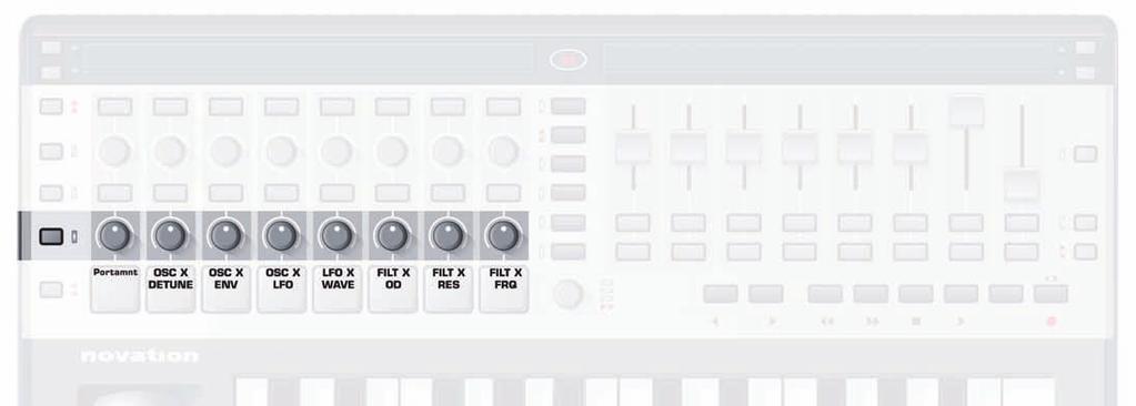
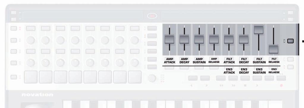
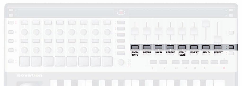
89 89
Combined pitch bend/modulation joystick GLOBAL) or carry out an action (WRITE, TAP TEMPO) Keyboard
 or carry out an action (WRITE, TAP TEMPO) Keyboard") CONNECTING TO A COMPUTER If wanting to use your ReMOTE SL to control software then the setup couldn t be simpler. As the unit is MIDI class compliant, no drivers are required so the only action to take
CONNECTING TO A COMPUTER If wanting to use your ReMOTE SL to control software then the setup couldn t be simpler. As the unit is MIDI class compliant, no drivers are required so the only action to take
Prophet '08 PlugSE Editor
 Prophet '08 PlugSE Editor SoundTower PlugSE for Prophet 08 Synthesizer VST (PC/Mac) AudioUnits (Mac) SoundEditor, PlugSE, and ipad Products Reach Inside... SoundTower Inc. 2012 www.soundtower.com Special
Copyright: Novation E.M.S Limited 2003 ReMOTE User Guide Version 1.5. Features and specifications subject to change without notice due to improvements
 Copyright: Novation E.M.S Limited 2003 ReMOTE User Guide Version 1.5 Features and specifications subject to change without notice due to improvements www.novationmusic.com CONTENTS Contents Introduction...
Editor/Plug-In Editor Manual
 Editor/Plug-In Editor Manual E Table of Contents Introduction... 1 Main features...1 Please note before use...1 M50 Editor and M50 Plug-In Editor operating requirements...1 Installation... Installation
Worlde TUNA MINI MIDI Controller User s Manual
 HANGZHOU WORLDE DIGITAL PIANO CO.,LTD WEBSITE: WWW.WORLDE.COM.CN EMAIL:SALES@WORLDE.COM.CN TEL:86 571 88730848 Worlde TUNA MINI MIDI Controller User s Manual -1- Contents 1. INTRODUCTION... 3 2. FEATURES...
FRONT PANEL OVERVIEW...1 REAR PANEL OVERVIEW...3 HOOKUP DIAGRAM...4 DISPLAYING INFORMATION...6
 TABLE OF CONTENTS FRONT PANEL OVERVIEW...1 REAR PANEL OVERVIEW...3 HOOKUP DIAGRAM...4 DISPLAYING INFORMATION...6 OCTAVE AND TRANSPOSITION...6 NOTE...6 NOTE AFTERTOUCH (Channel Pressure)...6 CONTROL CHANGE...6
User Guide. English. Manual Version 1.0
 User Guide English Manual Version 1.0 Table of Contents (Click a chapter/section to skip to it.) Introduction... 5 Box Contents... 5 Support... 5 About This User Guide... 5 Initial Setup... 6 1. Software/Driver
MainStage 2. Exploring MainStage
 MainStage 2 Exploring MainStage KKApple Inc. Copyright 2011 Apple Inc. All rights reserved. Your rights to the software are governed by the accompanying software license agreement. The owner or authorized
KURZWEIL Artis PlugSE
 KURZWEIL Artis PlugSE SoundTower PlugSE for KURZWEIL Artis Stage Piano VST (PC/Mac) AudioUnits (Mac) SoundEditor, PlugSE, and ipad Products Reach Inside... SoundTower Inc. 2014 www.soundtower.com Special
Axiom. User Guide. English
 Axiom User Guide Table of Contents.......................................................................... 3 Introduction...................................................................... 3 What
MCS 2 USB Software for OSX
 for OSX JLCooper makes no warranties, express or implied, regarding this software s fitness for a particular purpose, and in no event shall JLCooper Electronics be liable for incidental or consequential
Using Nektar Impact LX with Cubase & Nuendo
 www.nektartech.com www.nektartech.com Using Nektar Impact LX with Cubase & Nuendo Cubase Integration Installation and Setup The Impact LX Cubase Integration is compatible with Cubase 5, 6, 6.5, 7 and 8,
Using Nektar Impact LX with Reaper
 www.nektartech.com www.nektartech.com Using Nektar Impact LX with Reaper Reaper Integration Installation and Setup The Impact LX Reaper Integration is compatible with Reaper 4.59 or later. We recommend
Emote 1.0 Users Manual
 Emote 1.0 Users Manual Part No: 141318 Rev A 2018 Eventide Inc., One Alsan Way, Little Ferry, NJ, 07643 USA 1 Table of Contents Introduction... 3 Downloading the Installer... 3 Making Sure Your H9000 Hardware
MIDISynth-Circuit User Guide
 MIDISynth-Circuit 1.2.3 User Guide http://isotonikstudios.com/novation-x-isotonik/circuit-editor-vst-au/ http://sigabort.co/midisynth.html Table of Contents 1 Overview... 5 1.1 Requirements... 5 1.2 Limitations...
CONTENTS Template Parameter Edit 1 Page PROG CHG Messages. (just buttons/trigger pads/pedals) 1. Introduction
 1. Introduction") CONTENTS 1. Introduction 2. Connecting the ReMOTE SL 2. 1 Using the SL as a MIDI interface 2. 2 MIDI I/O within the sequencer 2. 3 Advanced routing options 3. Controlling with the ReMOTE SL 3. 1 PLAY Mode
CONTENTS 1. Introduction 2. Connecting the ReMOTE SL 2. 1 Using the SL as a MIDI interface 2. 2 MIDI I/O within the sequencer 2. 3 Advanced routing options 3. Controlling with the ReMOTE SL 3. 1 PLAY Mode
User Guide. English. Manual Version 1.1
 User Guide English Manual Version 1.1 Table of Contents Introduction... 4 Editing the Controls... 10 Information & Support... 4 Installation... 4 Overview... 10 Graphical User Interface... 10 Control Panel...
User Guide. English ( 3 16 ) Appendix English ( )
 Appendix English ( )") User Guide English ( 3 16 ) Appendix English ( 17 19 ) USB SUSTAIN C17 POWER ON OFF User Guide (English) Box Contents Oxygen 25 USB Cable Ableton Live Lite Software Download Card Quickstart Guide Safety
User Guide English ( 3 16 ) Appendix English ( 17 19 ) USB SUSTAIN C17 POWER ON OFF User Guide (English) Box Contents Oxygen 25 USB Cable Ableton Live Lite Software Download Card Quickstart Guide Safety
User Guide. Manual Version 1.0
 User Guide Manual Version 1.0 Table of Contents Introduction... 3 System Requirements and Product Support... 3 Installation... 3 Windows... 3 Mac OS X... 3 Quick Start... 4 Operation... 5 Global Controls...
Inear Display AMALGAME
 Inear Display AMALGAME User Guide Version 1.1 Table Of Contents Introduction 3 Overview 4 Installation and First Launch 5 Interface Overview 6 Loading and Saving Presets 7 Effects 8 XY Pad 9 Sequences
FM 4/100 USB Software for OSX
 FM 4/100 USB Software for OSX JLCooper makes no warranties, express or implied, regarding this software s fitness for a particular purpose, and in no event shall JLCooper Electronics be liable for incidental
Evolution UC-33e Getting Started. Evolution UC-33e Getting Started UC33
 20 1 Trouble-Shooting My Evolution hardware suddenly stopped working after having performed fine since installation. Switch off the unit and leave for 10 seconds. Then restart your computer and try again.
Introduction: -The Beat Kangz
 Introduction: Thank you for choosing Beat Thang Virtual as part of your creative process. As artists ourselves, we know how important this decision is. We understand that you have many products to choose
The Compact Make-Music-Now Keyboard Studio. English. User Guide
 The Compact Make-Music-Now Keyboard Studio English User Guide 1 Introduction.............................................................. 3 Session KeyStudio Features..............................................
OPERATION MANUAL VST / AU
 OPERATION MANUAL VST / AU This manual is under construction. If you want to help to improve it contact: info@audiorealism.se Introduction AudioRealism Bass Line 3 (ABL3) is an emulation of a classic pattern
Akai Pro Advance Series and VIP - Setup with Logic Pro X
 Akai Pro Advance Series and VIP - Setup with Logic Pro X Akai Professional's Advance Keyboards are like nothing else you've ever played. Along with the VIP software, the Advance series gives you unprecedented
MIDI HARMONISER PLUGIN
 Obelisk by FrozenPlain 1 MIDI HARMONISER PLUGIN www.frozenplain.com Obelisk by FrozenPlain 2 1 - WHAT IS OBELISK? Obelisk is a MIDI plugin instrument. Rather than produce audio, it produces MIDI. Obelisk
LiveProfessor 2. User Manual. Rev audiostrom.com
 LiveProfessor 2 User Manual Rev 1.0 - audiostrom.com Contents Introduction 4 System Requirements 4 License files 4 First Run 5 Installing Plugins Plugin Manager Audio Settings MIDI Inputs 7 Replacing A
MCS3 USB Software for OSX
 MCS3 USB Software for OSX JLCooper makes no warranties, express or implied, regarding this software s fitness for a particular purpose, and in no event shall JLCooper Electronics be liable for incidental
Circuit Editor PRO Read Me.
 EDITOR PRO READ ME Circuit Editor PRO Read Me. This document will guide you through editing patches and creating patches for your circuit. It will not be going into details of synthesizer patch design,
Midi Madness 3. Owner s Manual V3.0.2-RC1
 Midi Madness 3 Owner s Manual V3.0.2-RC1 Table of Contents Table of Contents... 2 Introduction... 3 Installation... 3 Registering... 4 Probability Concept... 4 Using Midi Madness... 6 The User Interface
MIDIPLUS Co, Ltd.
 MIDIPLUS Co, Ltd. http://www.midiplus.com.tw CONTENTS Preface... 1 What s in the Box?... 1 O62 Keyboard Overview... 1 Chapter 1:Quick Start... 2 1.1 O62 Overview... 2 1.1.1 Front panel Overview... 2 1.1.2
Using Impact LX with Reason
 Using Impact LX with Reason Applicable to Impact LX25, 49, 61 & 88 www.nektartech.com www.nektartech.com Using Impact LX with Reason Reason Integration Setup and Configuration The Impact LX Reason Integration
Seaboard RISE Creator Manual
 Seaboard RISE Creator Manual 1 Introduction Hello creator, and welcome to the Creator Manual for the Seaboard RISE. We think of the people who buy and use ROLI s products as creators more than customers.
nativekontrol PXT-Live Plus User Manual Version 1.0.8
 nativekontrol PXT-Live Plus User Manual Version 1.0.8 1 CHANGES IN THIS VERSION 2 GENERAL OVERVIEW 3 SETUP 3.1 Live Settings 3.2 UserPlusPreferences 4 GLOBAL CONTROLS 4.1 Touch Strip 5 PLUS MATRIX MODES
Work Smart: Windows 7 New Features
 About Windows 7 New Features The Windows 7 operating system offers several new features to help you work faster and more efficiently, and enable you to access the files, folders, programs, and applications
Using Panorama with Bitwig Studio
 www.nektartech.com www.nektartech.com Using Panorama with Bitwig Studio Bitwig Studio Integration Setup and Configuration The Panorama Bitwig Studio Integration is compatible with Bitwig Studio 1.3.5 and
Kameleono. User Guide Ver 2.1
 Kameleono Ver 2.1 Table of Contents Overview...4 MIDI Processing Chart...5 Kameleono Inputs...5 Kameleono Core...5 Kameleono Output...5 Getting Started...6 Installing...6 Manual installation on Windows...6
GETTING STARTED GUIDE. Features of the SP6
 GETTING STARTED GUIDE This Getting Started Guide will give you a quick overview of the SP6. A full manual with additional information is available from www.kurzweil.com. Features of the SP6 FlashPlay technology
A project is the basic file type in Cubase, in the same way that a document is the basic file type in Microsoft Word.
 CUBASE Menu > Cubase SL help The Cubase.net website: http://www.cubase.net/phpbb2/ A project is the basic file type in Cubase, in the same way that a document is the basic file type in Microsoft Word.
QUICKSTART GUIDE ENGLISH
 QUICKSTART GUIDE ENGLISH WWW.AKAIPRO.COM BOX CONTENTS LPK25 USB cable Software CD SOFTWARE CD Safety Instructions & Warranty Information PC Users: To install the Akai Professional LPK25 Editor, open the
QuantiChord. MIDI Chord Quantizer App & Audio Unit MIDI effect for ios
 QuantiChord MIDI Chord Quantizer App & Audio Unit MIDI effect for ios Presentation... 1 Application setup... 2 MIDI connections between ios applications... 2 MIDI over WiFi on macos... 3 MIDI over USB
Welcome Installation Authorization The T-Pain Engine: Quick Start Interface Sound Check... 10
 CONTENTS Welcome... 5 Installation... 5 Authorization... 6 The T-Pain Engine: Quick Start... 8 Interface... 8 Sound Check... 10 The T-Pain Engine: First Steps... 11 Beat... 11 Vocals... 14 FX... 15 Mixdown...
MOX6/MOX8 Editor VST Owner s Manual
 MOX6/MOX8 Editor VST Owner s Manual Contents What is the MOX6/MOX8 Editor VST?...2 Data Structure of the MOX6/MOX8 Editor VST...3 Starting the MOX6/MOX8 Editor VST...4 An Example of MOX6/MOX8 Editor VST
Sono 61. English User Guide
 Sono 61 English User Guide 1 Introduction.............................................................. 3 ProKeys Sono 61 Features............................................... 4 What s in the Box?.......................................................
USB / MIDI / CV KEYBOARD CONTROLLER
 USB / MIDI / CV KEYBOARD CONTROLLER 1. MAX49 2. AC 3. USB 4. CD (Vyzex AKAI CONNECT ) 5. DVD (Ableton Live Lite Akai Edition) 6. () AC () () () () 1. CD CD 2. : Windows : CD Vyzex installer (.exe) Mac:
Revision and Quality Control: Cristina Bachmann, Marion Bröer, Heiko Bischoff, Sabine Pfeifer The information in this document is subject to change
 MIDI Devices Revision and Quality Control: Cristina Bachmann, Marion Bröer, Heiko Bischoff, Sabine Pfeifer The information in this document is subject to change without notice and does not represent a
Push. Figure A4.1 Push.
 Push Figure A4.1 Push. Push is a hardware controller designed by Ableton and Akai to drive Live s Session View. Simply connect the Push unit using the provided USB cable to your computer and off you go.
Table of Contents. Introduction 2 1. Intelligent Remote Control 2 2. Charging the Remote Control 3
 Table of Contents Introduction 2 1. Intelligent Remote Control 2 2. Charging the Remote Control 3 Getting Started 6 1. Activating the Remote Control 6 2. Selecting a Device 7 3. Operating a Device 8 4.
MOTIF XF Editor Owner s Manual
 MOTIF XF Editor Owner s Manual Contents What is the MOTIF XF Editor?...2 Studio Manager...2 Studio Connections...2 About Open Plug-in Technology...3 Data Structure of the MOTIF XF Editor...4 Starting the
and close the various Traktor Panels. Setup: click on the setup icon to open the setup dialog. Close: clicking this icon will close TRAKTOR DJ Studio.
 Welcome... TRAKTOR DJ Studio 2 Quick Reference...to TRAKTOR DJ Studio 2, the latest and most advanced version of the software that changed the way DJs think about computers. We ve introduced a number of
Pro Tools Setup for Impact LX+
 Pro Tools Setup and Troubleshooting: Impact LX+ Pro Tools Setup for Impact LX+ First you will need to set the Impact LX+ keyboard to USB Port Setup Mode 3 1. Hold 'Shift/Mute' and press the 'Patch>' button
CV.OCD USER MANUAL. CV.OCD has four assignable continuous analog CV outputs and twelve assignable gate/trigger outputs. MIDI-TO-CV
 six4pix.com/cvocd CV.OCD USER MANUAL Introduction CV.OCD is a device which converts MIDI signals to the Control Voltage (CV) and Trigger/Gate signals which are used to control traditional analog synthesizers.
Editor v User's Manual.
 Editor v. 1.00 User's Manual www.genuinesoundware.com - 1/42 Welcome to the user's manual for the GSi DMC-122 Editor. This application for Windows and OS X operating systems lets you configure every aspect
Installing the VS-700 Control Surface Plug-in
 Installing the VS-700 Control Surface Plug-in 1. Close all programs and any open windows. If you are running any antivirus programs the prevent software installation these will need to be disabled. 2.
25/37/49/61-note velocity-sensitive piano-style keys USB MIDI controller keyboard. ikeyboard 3. ikeyboard 4. ikeyboard 5. ikeyboard 6.
 25/37/49/61-note velocity-sensitive piano-style keys USB MIDI controller keyboard ikeyboard 3 ikeyboard 4 ikeyboard 5 ikeyboard 6 User manual Important Safety Instructions 1. Read this manual thoroughly
SuperNova. Magnifier & Speech. Version 15.0
 SuperNova Magnifier & Speech Version 15.0 Dolphin Computer Access Publication Date: 19 August 2015 Copyright 1998-2015 Dolphin Computer Access Ltd. Technology House Blackpole Estate West Worcester WR3
AUDIO VIDEO MEDIA CONTROLLERS. EuCon Application Setup Guide. Document Revision: K
 EuCon Application Setup Guide Document Revision: K MC Control, MC Mix, MC Transport, Studio Monitor Express, Studio Monitor Pro, EuControl, EuCon and EuCon Powered are trademarks of Euphonix Inc. All other
DROP-X. Drag & Drop - Beat Repeat Sampler USER MANUAL. VST / AU / AAX Plugin Mac OSX / WIN 32 / 64 bit
 DROP-X Drag & Drop - Beat Repeat Sampler VST / AU / AAX Plugin Mac OSX / WIN 32 / 64 bit USER MANUAL BEAT SKILLZ 10 SOUND BANKS - OVER 250 PRESETS Features: DropX is a very easy to use Drag & Drop Sampler
Firmware Version 1.60 User s Guide
 MZ-X500 EN MZ-X300 Firmware Version 1.60 User s Guide MZX500/300-160-E-1A 1 Updates Provided by Firmware Version 1.10 Firmware changes provided by Version 1.0X are those described below. Addition of a
User Guide FFFA
 User Guide FFFA001508-01 www.focusrite.com Contents Introduction... 3 About this User Guide...3 System Requirements........................................................ 4 Software Installation... 4
HALion 4. Version history Known issues & solutions. Januar 2013 Steinberg Media Technologies GmbH
 HALion 4 Version history Known issues & solutions Januar 2013 Steinberg Media Technologies GmbH Table of contents About... 3 HALion 4.5.4... 4 Issues resolved... 4 HALion 4.5.3... 5 Improvements... 5 Issues
Axiom DirectLink for Cubase User Guide
 Axiom DirectLink for Cubase User Guide Legal Notices This guide is copyrighted 2010 by Avid Technology, Inc., with all rights reserved. Under copyright laws, this guide may not be duplicated in whole or
User Manual v1.5.
 User Manual v1.5 www.directsynth.com 1 Introduction Thank you for choosing our product, we wish you lot of fun using it. What is EMX? The EMX, also known as «Electribe MX» is a hardware audio workstation
EUCON Application Setup
 EUCON Application How to install EuControl Software to use Avid media controllers with applications from Avid and our EUCON Development Partners Introduction Overview of Avid Media Controllers Avid Pro
Basic Concepts 1. For this workshop, select Template
 Basic Concepts 1 When you create a new presentation, you re prompted to choose between: Autocontent wizard Prompts you through a series of questions about the context and content of your presentation not
MOTIF XS Editor VST Owner s Manual
 MOTIF XS Editor VST Owner s Manual Contents What is the MOTIF XS Editor VST?...2 Data Structure of the MOTIF XS Editor VST...3 Starting the MOTIF XS Editor VST...4 An Example of MOTIF XS Editor VST in
User Guide FFFA
 User Guide FFFA001508-02 www.focusrite.com Contents INTRODUCTION... 3 About this User Guide...3 SYSTEM REQUIREMENTS........................................................ 4 SOFTWARE INSTALLATION... 4
MorphEdit for Windows. Copyright 1994,1995,1996 PJA White
 MorphEdit for Windows Copyright 1994,1995,1996 PJA White Table of Contents 1. INTRODUCTION... 1 2. REQUIREMENTS... 2 3. INSTALLATION... 3 4. STARTING THE EDITOR... 4 5. MODES OF OPERATION... 5 5.1 STAND-ALONE
Worlde Orca PAD64 MIDI Controller User s Manual
 Worlde Orca PAD64 MIDI Controller User s Manual - 1 - CONTENTS 1. INTRODUCTION... 4 2. FEATURES... 4 3. PARTS AND THEIR FUNCTIONS... 6 3.1 Orca PAD64 Overview... 6 3.1.1 Top Panel Overview... 6 3.1.2 The
COPYRIGHT AND LEGAL NOTICES. Trademarks. Disclaimer. English
 Novation A division of Focusrite Audio Engineering Ltd. Windsor House, Turnpike Road, Cressex Business Park, High Wycombe, Bucks, HP12 3FX. United Kingdom Tel: +44 1494 462246 Fax: +44 1494 459920 e-mail:
J74 Volca Control - Instructions and FAQ
 J74 Volca Control - Instructions and FAQ http://www.fabriziopoce.com/vc_faq.html [1] - What do I need to make use of the VolcaControl devices (VKeys, VBeats, VBass)? You need the Volca unit or units, a
User Manual. Drum Machine
 User Manual Drum Machine Overview Interface Overview Interface 1 Nithonat s interface is split into three parts: Internal sequencer Responsible for editing patterns in Int.Seq. mode. Internal sequencer
User Guide
 www.nektartech.com www.nektartech.com User Guide Table of Contents Introduction 4 Box Content 4 Panorama T4/T6 Features 4 Minimum System Requirements 4 Getting Started 5 Connection and Power 5 Getting
TB-303. Software Bass Line Owner s Manual Roland Corporation 01
 TB-303 Software Bass Line Owner s Manual 2019 Roland Corporation 01 Introduction For details on the settings for the DAW software that you re using, refer to the DAW s help or manuals. About Trademarks
Manual addendum written by Nadine Raihani, Cornelius Lejeune Manual version: 1.3 (09/2008) Software version: 2.0.4
 Software version: 2.0.4") MANUAL ADDENDUM The information in this document is subject to change without notice and does not represent a commitment on the part of NATIVE INSTRUMENTS GmbH. The software described by this document
MANUAL ADDENDUM The information in this document is subject to change without notice and does not represent a commitment on the part of NATIVE INSTRUMENTS GmbH. The software described by this document
KARMA Motif Using the Remote Mode S70/S90 XS
 KARMA Motif Using the Remote Mode S70/S90 XS Revision 07-Oct-2014 by Stephen Kay www.karma-lab.com Overview Note: the use of S90 XS in this document refers to either an S70 XS or an S90 XS. The information
Digitakt OS 1.07 Release Information
 Digitakt OS 1.07 Release Information Elektron Music Machines March 9, 2018 How to upgrade: Upgrading from within the OS Select SYSTEM in the SETTINGS menu, and then select OS UPGRADE. Send the SysEx firmware
StepPolyArp Unit. Step Polyphonic Arpeggiator / Sequencer App & Audio Unit MIDI effect for ios
 StepPolyArp Unit Step Polyphonic Arpeggiator / Sequencer App & Audio Unit MIDI effect for ios Presentation... 1 Application setup... 2 MIDI connections between ios applications... 2 MIDI over WiFi on macos...
Digitakt OS 1.06 Release Information
 Digitakt OS 1.06 Release Information Elektron Music Machines February 12, 2018 How to upgrade: Upgrading from within the OS Select SYSTEM in the SETTINGS menu, and then select OS UPGRADE. Send the SysEx
WAVES BASS RIDER USER GUIDE
 WAVES BASS RIDER USER GUIDE TABLE OF CONTENTS Chapter 1 Introduction...3 1.1 Welcome...3 1.2 Product Overview...3 1.3 Concepts and Terminology...4 1.4 Components...5 Chapter 2 Quick Start Guide...6 Chapter
FaderPort. Quick Start Guide. English.
 FaderPort www.presonus.com English Table of Contents 1 Introduction 1 1.1 About This Guide 1 1.2 What s in the Box 1 2 Hookup 2 2.1 Getting Started 2 3 Connections and Controls 3 3.1 Controls 3 3.2 Connections
KARMA Motif Getting Started
 KARMA Motif Getting Started Revision 07-Oct-2014 by Stephen Kay www.karma-lab.com Prerequisites Please perform the steps in the Installation and First Launch tutorial before beginning this one. Note: the
Procussion operation manual Basic Operation 15 BASIC OPERATION
 Basic Operation 15 BASIC OPERATION 16 Main Controls 17 BASIC OPERATION MAIN CONTROLS MIDI ACTIVITY EDIT MENU SELECT CURSOR CONTROL VOLUME CONTROL I/O MASTER EDIT ENTER C01 Vol127 Pan=K CURSOR DATA VOLUME
PS04 Pattern Editor. Last Update: Feb,
 PS04 Pattern Editor www.soundside.de Last Update: Feb,12 2004 Index 1. Introduction. 2. Overview of the Pattern Editor. 3. Setting up the Pattern Editor. 4. Loading and playing a Rhythm Pattern in the
IMPORTANT NOTE: If you are new to using pkcomponents and/or MT Player or if you need Support, please refer to the pkc-general Manual.
 Preset: pkc-lrn v1.0.0 NOTE: There are 2 versions of this Preset. pkc-lrn is the default version. pkc-lrn[thru] is the same as the default version except that it passes Thru MIDI from a 2nd controller.
MIDI Expression User Manual
 MIDI Expression User Manual Quattro io Updated 03/01/2018 Table of Contents Introduction...3 Routing and Effects...17 Features...3 MIDI Effects Processor...17 Pedal Sensing Technology...3 Routing...17
Contents. Introducing Clicker Paint 5. Getting Started 7. Using The Tools 10. Using Sticky Points 15. Free resources at LearningGrids.
 ClickerPaintManualUS.indd 2-3 13/02/2007 13:20:28 Clicker Paint User Guide Contents Introducing Clicker Paint 5 Free resources at LearningGrids.com, 6 Installing Clicker Paint, 6 Getting Started 7 How
User Manual v1.1.
 User Manual v1.1 www.directsynth.com 1 Introduction Thank you for choosing our product, we wish you lot of fun using it. What is ESX? The ESX, also known as «Electribe SX» is a hardware audio workstation
INSTRUCTIONS FOR MIDI INTERFACE
 INSTRUCTIONS FOR MIDI INTERFACE MICROMOOG USING THE MIDI INTERFACE - - - When you turn on the synthesiser for the first time, you will be in omni-on mode for receive (all channels). When you select a receive
MPC Essentials Release Notes
 MPC Essentials Release Notes About Akai Professional is continually updating and enhancing MPC Essentials. This document lists the new features, fixes and improvements made to your MPC Essentials software.
Features List MK-425C/MK-449C & MK-461C
 Getting Started Introduction Introduction Congratulations on your purchase of your Evolution USB keyboard. You can use it to play virtual instruments on PCs and Macs, and to control external MIDI hardware
VST-AU Pulse Editor User Manual. Windows XP, Vista, Windows 7 OSX 10.5, 10.6
 VST-AU Pulse Editor 2.1.0 User Manual Windows XP, Vista, Windows 7 OSX 10.5, 10.6 VST-AU Pulse Editor 2.1.0 User Manual Table of Contents» Introduction» Installation» MIDI Setup» Working with the VST-AU
TriplePlay Release Notes
 TriplePlay Release Notes Last Update: 2013 08 20 (mc) Release: Win 1.1.3204 / Mac 1.1.3204 / C 2.07 / R 1.76 Definitions Standalone This refers to the TriplePlay application running by itself and not as
GRAND HD CINEMA PRO. User s Manual INDEX
 INDEX GRAND HD CINEMA PRO USB to HDMI Converter User s Manual 1. Package Contents....... 1 2. Introduction........ 1 3. System Requirement.... 1 4. Product Features...... 2 5. Hardware Overview...... 2
User Guide. FTR Reporter For more information, visit
 FTR Reporter 5.7.1 For more information, visit www.fortherecord.com TABLE OF CONTENTS INTRODUCTION... 5 Overview... 5 About This Document... 5 GETTING STARTED... 6 Installation... 6 Starting Reporter...
GETTING STARTED. Welcome To Trilian!
 GETTING STARTED Welcome To Trilian! GETTING STARTED Quickstart This Quick Start provides an overview of the essential things you will need to know in order to get started using Trilian. Trilian is a software
Lenovo Miix User Guide. Read the safety notices and important tips in the included manuals before using your computer.
 Lenovo Miix 2 11 User Guide Read the safety notices and important tips in the included manuals before using your computer. Notes Before using the product, be sure to read Lenovo Safety and General Information
WAVES MASERATI B72 User Guide
 WAVES MASERATI B72 TABLE OF CONTENTS CHAPTER 1 INTRODUCTION...3 1.1 WELCOME...3 1.2 PRODUCT OVERVIEW...3 1.3 A FEW WORDS FROM TONY MASERATI...4 1.4 COMPONENTS...4 CHAPTER 2 QUICKSTART GUIDE...5 CHAPTER
MIDISynth-Control 1.0.6
 MIDISynth-Control 1.0.6 https://itunes.apple.com/us/app/midisynth-control/id1366849280 http://www.sigabort.co/msc_android_demo.html Table of Contents 1 Overview... 4 1.1 Requirements... 4 1.1.1 ios...