AKELA Vector Network Analyzer (VNA) Quick Start Guide
|
|
|
- Harriet Nelson
- 5 years ago
- Views:
Transcription
 Quick Start")
1 AKELA Vector Network Analyzer (VNA) Quick Start Guide
2 Copyright AKELA, Inc. 2012, all rights reserved LabVIEW and LabWindows are registered trademarks of National Instruments Incorporated Excel is a registered trademark of Microsoft Incorporated MATLAB is a registered trademark MATHWORKS Incorporated
3 CONTENTS AKELA VNA Evaluation Kit Contents 4 Front Panel 5 Connecting the VNA 5 Unit Status Lamps 6 Connecting to a PC or Network 6 Installing the AKELA VNA Application 8 Updating the AKELA VNA Application 8 Starting the AKELA VNA Application 8 VNA Display and Control 10 Stimulus Control Panel 13 Calibration Control Panel 14 Display Control Panel 15 Marker Control Panel 16 Data Control Panel 18 State Control Panel 19 Special Control Panel 20 Making Measurements 21 Appendix A 23 3
 and S-Parameter Test Set")

4 AKELA VNA Evaluation Kit Contents The evaluation kit contains all the equipment required to evaluate the AKELA VNA. Software Installation CD Vector Network Analyzer Assembly, AKELA Vector Stimulus Unit (AVMU) and S-Parameter Test Set 12VDC Power Adapter and Power Cord Network Cable, Cat 5E Crossover (null modem) 2 Type N Male to SMA Female Adapters 2 SMA Male to SMA Male Coaxial Cables, 12 inch Economy SMA calibration kit, 50Ω Load, Short, and Open 915 MHz Band Pass Filter 4

5 Port 1 Status Lamp AKELA VNA Front Panel S-Parameter Test Set Port 2 Status Lamp Stimulus Measurement Unit (AVMU) Port 1 and Port 2 Status Lamps indicate which S-Parameter Test Set port is active. Connecting the VNA Connect the 12VDC Power Adapter cables to the AC Mains and the 12VDC connector on the Stimulus Measurement Unit. Use the supplied Cat 5E network cable to connect the Stimulus Measurement Unit to the Ethernet port on your PC or system network. To turn the VNA On or Off, press and hold the power button for 2 seconds. 5

6 The VNA Status Lamps PWR: On when power is applied SCAN: On when measurements are being acquired LAN: On when connected to a network/pc NETW ACTY: Flashes when network activity is detected BATTERY: Indicates state of charge when using external battery power FAULT: Indicates an internal fault has occurred, e.g. over temperature, over current, under voltage, etc. Connecting To A PC Or Network Communication with the AKELA VNA is through the 100 Base-T Ethernet connection and may be accomplished either by direct connection to a computer or over a LAN. The Ethernet cable supplied in the evaluation kit is a Cat 5E crossover cable and may be used for connecting the VNA to a computer or LAN. Since the VNA does not automatically sense TX/RX polarity, a crossover cable must be used if the computer or LAN connected to the VNA does not automatically sense polarity. Each VNA is assigned an Ethernet Address in the range of to as the factory setting. This address is fixed. The VNA shipped in the evaluation kit is set to IP The VNA does not implement the DHCP protocol and does not support Internet Control Message Protocol functions such as PING. 6
7 If the VNA is connected to a LAN through a switch or router, the VNA should be able to communicate without any changes to your computer network settings. If the VNA is connected to a computer directly, the user will need to change the computer's IP address setting to a fixed IP address that is in the same range as the VNA s. To set the IP address of your computer, go to the properties tab of the network interface on your computer, select Advanced, select Internet Protocol, Properties, click on use the following IP address and set the fixed IP address. When setting the computer to a fixed IP address, it must be in the range of to excluding the address of the VNA ( ). Set the subnet mask to After the IP address of your computer has been set, the VNA application should be able to communicate with the VNA normally. On some computers, the user may need to disable any other network connections (e.g. wireless connection) that are not connected to the VNA. AKELA VNA Application Program Installation The software package distributed with the AKELA Vector Network Analyzer provides a LabVIEW-based application that executes under the LabVIEW 8.6 Run-Time Engine. The software will install the National Instruments LabVIEW 8.6 Run-Time Engine and the AKELA VNA application to your computer. It is not possible to modify the AKELA VNA application, access the AKELA VNA drivers, or create new LabView applications using the installed software. The user must obtain a separate license from National Instruments to modify the AKELA VNA application or create their own LabView applications for the AKELA VNA. 7
8 Application Installation Insert the software installation CD into your CD drive. Navigate to the CD drive. In the root folder of the CD Drive, double click on the file Setup. exe. The Destination directory window will display. To install software in a different location, click the browse button and select another directory. Click Next when done. The Start Installation Dialog will appear. Click next to begin installation. When installation of the software is complete, click the Finish button. Updating the AKELA VNA Application Should you need to update the VNA application after initial installation of National Instruments LabWindows/CVI Run-Time Engine, an application update archive will be provided. You will be replacing the AKELA VNA Application and the initialization files in the installation folder. Close the AKELA VNA application if it is running. Save the update archive file, typically named AKELA VNA Update V1_xx.zip, to a location on your computer. Use the Windows Zip file Extraction Wizard to extract the files from the archive. Copy the extracted files, including the data folder, to the AKELA VNA installation folder, usually C:\Program Files\AKELA VNA, overwriting the existing files. There is no need to restart the computer after an update is installed. Starting the AKELA VNA Application For Microsoft Windows Vista or Windows 7 installations, the user will need to allow the AKELA VNA application to Run as an administrator. From the start menu, right click on the AKELA VNA 8

9 start menu item, select Properties, select the Compatibility tab and check the Run this program as an administrator box, then click OK. To start the AKELA VNA application, go to the start menu and click on the AKELA VNA program item. The VNA application will start and display an informational notice, Searching for AVMU units. If the VNA application fails to find any AVMU units attached to the network, it will display the informational message, No AVMU units found. Click OK to continue. If the user has no AVMU (VNA) attached to the network, the AKELA VNA application will begin to run using simulated data, thereby allowing the user to explore the features and controls of the AKELA VNA application. If the user has an AKELA VNA connected to the network but the VNA application fails to detect the VNA, some common reasons for this may be: - The VNA is connected directly to the Ethernet Port on the computer and a static IP address has not been set. - The VNA is connected directly to the Ethernet Port on the computer and a crossover Ethernet cable is required. - There is an IP address conflict on the network. For example, a DHCP server may have assigned the VNA IP address to another 9
10 computer or device. If the user's network has static IP addresses assigned, identify the device and assign it a new, non-conflicting IP address, and exclude the VNA IP address from the DHCP server's automatic assignment list. AKELA VNA Display and Controls The left side of the VNA application display area is dedicated to data display. One, two, or four measurement display panes may be selected. The right side of the VNA application display area is dedicated to the control panels, where the user may access the controls available in the application. 10

11 To access the different control panels within the VNA application, click on the tabs on the right edge of the display area. Most of the controls and features will be familiar to anyone experienced with the use of RF Network Analyzers in general. The location and function of many of the on screen display controls are illustrated and described in the next section. VNA Display Data Area The VNA application is capable of displaying all four of the measured S-Parameters at the same time. The active RF paths are selected in the Stimulus Control Panel. Axis Scale minimum and maximum values for each display pane may be changed by double clicking on the Axis Scale End Point values on the display pane and entering the desired values. The 11
12 display's X and Y Axes may also be set by clicking on the X and Y auto scale buttons. The display panel Zoom, Pan, Marker, and Scale controls are shown below. Zoom tool Marker tool X-Axis autoscale S parameter selection Pan tool Y-Axis autoscale X-Axis scale controls Y-Axis scale controls The S-Parameter pull down menu allows selection of which S- Parameter will be shown in the display pane. Click on the Pan tool to enable panning the data in the X and Y Axis. Click on the Zoom tool to display and select the zoom options. Click on the Marker Tool to enable moving the markers within the display pane. In the Zoom and Marker Tool control group the selected option will persist within that display pane until another function is selected. Click the X and Y Axis Auto-scale buttons to auto-scale the X or Y Axis within the display pane. Click the X and Y Axis scale control buttons to display, select and set additional Axis scale control functions. The data format and scaling for each display pane may be set independently. The available display formats are: Real, Imaginary, Log Magnitude, Phase, Delay, Polar, Smith Chart, FFT (magnitude) and Data format selection Marker X axis value 12 Marker Y axis value

13 FFT (phase). Click on the Data Format Selection box and select the desired format for that display pane's data. The Marker Value Displays show the X and Y axis values for each of the data markers. Click on the desired marker box to turn the marker on and off. Stimulus Control Panel This panel allows you to control all of the stimulus parameters of the VNA and to select which S-Parameter paths to measure. S-Parameters to measure are selected with the radio buttons in the Active RF Paths selection box. Start and stop frequencies for the sweep are entered in the F min and F max text boxes. Each text box will support frequency values with up to 3 decimal places over a range from 250 to 2048 MHz. The arrows next to the text boxes will change the frequency in steps of 1 MHz. There are 12 selectable frequency hopping rates varying from 0.04 to 45 khz that are selected by clicking in the text box, or by using the arrows next to the text box. The number of points per frequency sweep is entered directly in the text box with valid values being from 2 to 4096 points. The nominal receiver gain setting for VNA operation is 6 db. Except under special conditions the valid gain values are 0, 3 and 6 db, since higher values will exceed the dynamic range of the measurement receiver. Attenuation in the transmit path can be set to values between 0 and 31 db in steps of 1 db. The setting selected is applied to both Ports 1 and 2. If the user s Device Under Test 13

14 (DUT) has gain, the receiver gain must be reduced, or the attenuation value increased by an amount equal to the DUT gain to maintain measurement accuracy. All of the other boxes in this panel are informational. Single path time is the time it takes to make a single S-Parameter measurement. Unambiguous delay is the maximum delay, or FFT time, that can be accurately displayed with the current bandwidth and number of points selected. The status box shows the current state of VNA data acquisition. To stop the data acquisition process, click on the Quit button. To restart, click the run arrow in the upper left corner of the main display. Calibration Control Panel AKELA s VNA comes with a factory calibration file so the VNA may be used immediately for making measurements as long as there are no special test fixtures involved in your test measurement setup. Each VNA is calibrated at the factory before shipment using the maximum VNA resolution with precision calibration standards. A factory calibration file is shipped with each VNA and is stored in the data folder within the VNA application installation folder with a name of the form Factory004.tdms where the last three numbers in the file name are the serial number of the VNA. The calibration file is automatically loaded at startup. During normal operation The calibration file will be interpolated by the calibration routine if the user s setting are different from those used at the factory to allow for different stimulus settings without completely invalidating the calibration. For the best ac- 14
15 curacy corrected data, however, a calibration should be performed for your particular stimulus settings. Both 1-Port and 2-Port calibrations are supported in the calibration control panel with the procedure for each being similar. For a 1-Port calibration, select the port for which the calibration is desired and then click on the buttons one at a time to be guided through the calibration using an Open, Short, and Load. The 2-Port calibration requires more steps because it calibrates both ports and includes a Through measurement. In Simulate mode, the Calibration functions are not available. After calibration, the calibration may be saved as a file for later use by pressing the Save cal file button and providing a suitable name for the file. The file may be recalled for use at a later time by using the Load cal file button. You may also specify which calibration to use by clicking in the Calibration to use text box and selecting 1-Port, 2-Port, or None. If None is selected, the uncorrected data will be displayed but the current calibration data will not be cleared from memory. At any time during VNA operation, you may determine the stimulus conditions under which the current calibration in use was performed. This is displayed in the Native Range box. For best results this should match the current VNA stimulus settings. If the calibration being used is from a previous calibration file that has been loaded, the name of the file will be displayed in the text box below the Clear button. The Clear button clears the current calibration data from memory. When the calibration data is cleared from memory the VNA displays raw uncorrected data. Display Control Panel This control panel allows you to control the number of VNA display panes and to select the number of VNA sweeps to aver- 15


16 age for smoothing the displayed data. One, two, or four display panes can be selected by using the associated radio buttons. Each display pane is identified by a letter A through D. These letters are used by the VNA application when using Markers and performing Marker Math and show up in the lower left corner of each display pane. The radio button for the selected option is highlighted. To choose the number of sweeps to average, enter the value into the text box and then press the Reset button. The status bar underneath the text box will turn red until the desired number of sweeps has been reached. The maximum value allowed is 512. Marker Control Panel Up to five markers are available for each display pane. The the scroll bar to the side of the Marker selection area will allow you to navigate to the selection boxes for display panes B through C to select additional markers. Markers are enabled or disabled by clicking on the marker buttons, A1, A2... B1, B2..., etc. for each display pane. When selected, a marker is highlighted in color. Markers can be of two types, Data or Free. Data makers are tied to a data point on a display pane trace, while 16


17 Free markers may be placed anywhere within a display pane. This is useful for setting targets or limits on screen. Select the type of marker by using the arrows next to the Type text box associated with the marker. The value for the marker is entered in the Position text box associated with each marker. Marker values will only be shown to one decimal place. Markers are normally independent among the selected display panes. However, they may be linked between panes by using the Marker Links area of the control panel. First select a link by clicking on a radio button. Clicking on the first marker selection box will produce a fly out menu that will allow you to check which marker to begin the link. Clicking on the second selection box will similarly allow you to select the marker number that finishes the link. To unlink the marker simply click the radio button again. When linked, markers track between the selected display panes. To access additional marker pairs to link, use the scroll bar to the side of the Marker Links selection area. 17


18 AKELA s VNA application will automatically do calculations using data values associated with markers. Clicking on a Marker Math radio button will enable or disable this capability. Marker math is enabled when the radio button is highlighted. As with selecting marker links, clicking on a marker selection box will produce a fly out menu that allows you to select which marker to use for calculation. The mathematical operation performed on the marker data values is selected by clicking on the mathematical symbol between the two marker selection boxes. Choose from one of the four available functions, +, -, * and /. The result of the math operation is displayed in the text box. Data Control Panel The Data Control Panel provides a variety of methods for you to save data for later analysis, test reporting, or performance archiving. You may export the current data from all open display panes directly to a Microsoft Excel spreadsheet for custom processing. With Excel open, click on the Export to Excel button. In this option, a separate file is not saved so it will be necessary to save the Excel spreadsheet if you want a permanent file record. Alternatively, you may export the data directly to a file in a comma separated variable format (CSV). Clicking the Export to CSV button saves the current data from all open display panes to a CSV file that may be read later with Excel or other applications such as MATLAB. 18
 button saves the current data to a full 2-Port S-Parameter file for Ports 1 and 2.")
19 The Export to S1P (1) and (2) buttons allow you to save current data to a 1-Port S-Parameter file for Ports 1 and 2 respectively. The Export to S2P (1) button saves the current data to a full 2-Port S-Parameter file for Ports 1 and 2. To save a single frame of data for the current data acquisition or to load a previously saved single frame of data, use the Save snapshot and Load Snapshot buttons respectively. A loaded snapshot file will allow you to view and manipulate the saved data in the VNA application. Similarly, the Save stream and Load stream buttons allow you to save and reload a time history of data to view and manipulate in the VNA application. State Control Panel When the quit button is pressed or the VNA is turned off, the current operating setup state is saved and reloaded upon system startup. While this is convenient, it is often useful to be able to recall a previous operating state to minimize setup time after changing to a different type of measurement. This panel allows you to both save special setup states of the VNA, and to reload them at a later time. The state includes all of the stimulus, calibration, display, marker, and special values that you have selected to define the current operation of the VNA. Use the Save state and Load state buttons to perform these operations. The Startup tab allows you to specify which Control panel to show beside the Data Display Area on system startup. Clicking on the Startup tab will produce a fly out menu from which you can select the desired control panel. In order to save or load a state, the VNA application must be running. 19


20 Special Control Panel This control panel provides a set of advanced functions. The Memory functions allow you to store a snapshot of the current data traces to the application memory. Click on the Capture button to store the traces to memory. Once the traces are stored, you will be able to change a DUT and use the Operation text box to select a mathematical operation for comparing the traces in memory with the current data traces. Click on Clear to clear the current data from memory. A reference plane extension is normally used to adjust the reference plane of the measurements to compensate for removal of the calibration standards, or to adjust for test fixture reference plane offsets. The Reference plane extension area of this control panel allows you to make this adjustment electronically. Use the slider or the up down controls to adjust the reference planes of the test ports. You may also input a value directly into the text box. The Unwrap Phase button will automatically perform a best straight line fit of the unwrapped phase of the current data in the target window. This is useful for rapidly adjusting for large phase offsets in a test configuration, for example removing the phase and time delay of long test cables. The Plot Options text boxes allow you to select the units (dbm, dbv, Degrees, Radians) for the display pane data plots and to set the reference for the Smith chart and the number of FFT points. 20
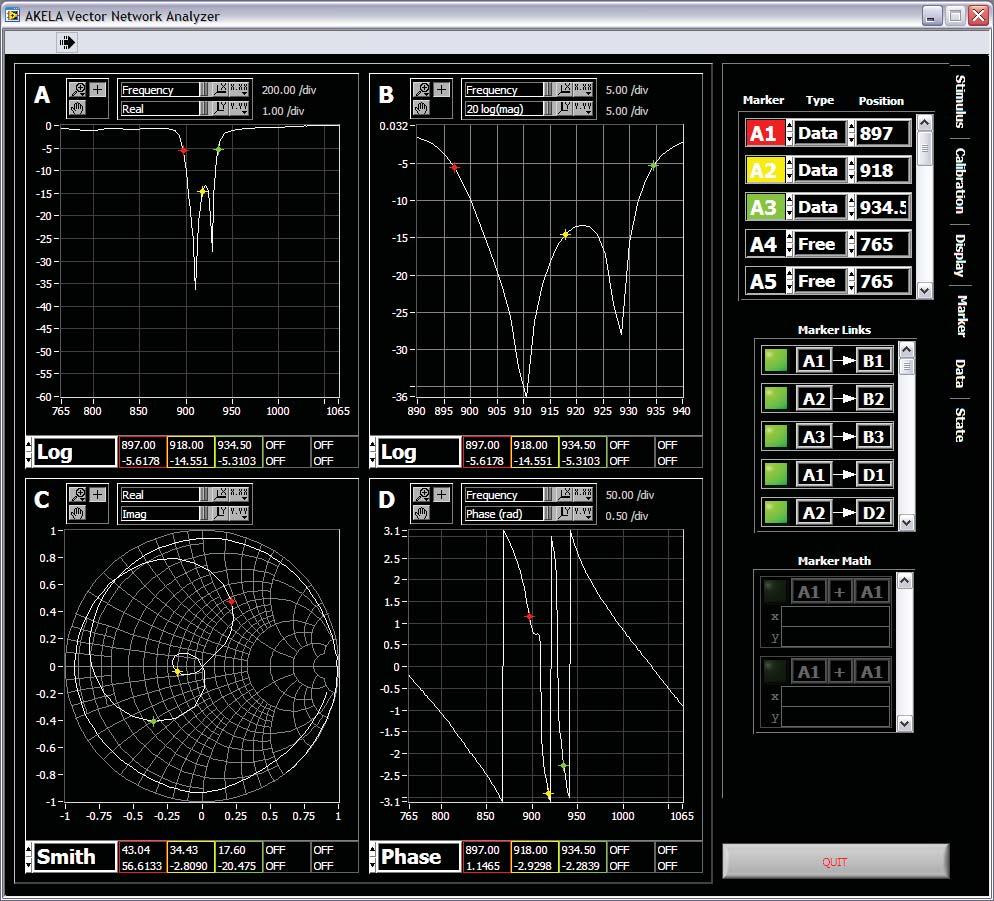
21 Making Measurements The AKELA VNA operates in much the same way as any other Vector Network Analyzer. However, there are a few differences that are noteworthy. VNA control functions that have been changed in the control panels only take effect if the VNA application is running and acquiring data. If the VNA application has been stopped using the Quit button, the application will need to be restarted using the start arrow on the upper left of the main display area in order for any operating parameter changes to take effect. The AKELA VNA takes a complete set of S-Parameters with every measurement cycle, acquiring S11, S21, S12, and S22 as well as a set of reference measurements used by the internal calibration routines. If the user's Device Under Test (DUT) exhibits gain, the VNA Gain must be reduced or the VNA attenuation setting must be increased (reduced output stimulus power). These controls are found on the Stimulus control panel. The output power or receive gain must be adjusted by an amount equivalent to at least the gain of the DUT. Example measurement Connect the 915 MHz Band Pass Filter supplied with the evaluation kit between Test Port 1 and Test Port 2. Start the VNA application. From the State control panel, click on Load State, browse to the installation folder where the VNA application was installed, then open the data folder and click on the state file: S12_765M_1065M_915M_BPF_30K_401Points_4panes_FFT. tdms Click on OK and the VNA display should appear as shown on the next page. 21
22 22
23 Appendix A External communication with the AKELA VNA application The AKELA VNA software can be integrated into your workflow in several ways: 1) ActiveX (Microsoft Automation) support enables the AKELA VNA software to export its measurement results to another software package at runtime, such as Excel, Igor Pro, Origin, and others. 2) For customers with existing LabVIEW work flows, AKELA can deliver subvis tailored to your needs - whether that be a platform on which to build your own new features, or simply a measurement subvi. 3) As a Windows DLL, the AKELA VNA software can be accessed by any in-house software. Contact AKELA for more information on how to integrate AKELA VNA software with your workflow. 23

24 5276 Hollister Avenue, Suite 263, Santa Barbara, CA / , FAX 805/ ,
Engineering Data Management Software. User s Guide. CoCo DSA Mode Spider Real-Time Mode Post Analysis Mode (CoCo VDC Mode not included)
") EDM USER S MANUAL Engineering Data Management Software User s Guide CoCo DSA Mode Spider Real-Time Mode Post Analysis Mode (CoCo VDC Mode not included) Version 1.00 Crystal Instruments Corporation 4699
EDM USER S MANUAL Engineering Data Management Software User s Guide CoCo DSA Mode Spider Real-Time Mode Post Analysis Mode (CoCo VDC Mode not included) Version 1.00 Crystal Instruments Corporation 4699
TTR500 Series Vector Network Analyzers Demonstration Guide
 xx ZZZ TTR500 Series Vector Network Analyzers Demonstration Guide *P071349301* 071-3493-01 xx ZZZ TTR500 Series Vector Network Analyzers Demonstration Guide Register now! Click the following link to protect
HP 8714B Calibration
 Wireless Circuits and Systems Laboratory Procedure #7 Calibrating the HP 8714 Network Analyzer This procedure describes the different types of calibrations that are available with the HP 8714 vector network
Section 1 Establishing an Instrument Connection
 Manual for Sweep VI Fall 2011 DO NOT FORGET TO SAVE YOUR DATA TO A NEW LOCATION, OTHER THAN THE TEMP FOLDER ON YOUR LAB STATION COMPUTER! FAILURE TO DO SO WILL RESULT IN LOST DATA WHEN YOU LOG OUT! 1.1.
Cal-Bay Systems XY Plotter, Time-Base Recorder, Automated Tester. Users Guide. Rev 3.1
 Cal-Bay Systems XY Plotter, Time-Base Recorder, Automated Tester Users Guide Rev 3.1 Contents... 1 Quick Start Guide... 2 Selecting a Test Specification... 3 Clearing Traces... 4 Saving Traces...4 Loading
RF Characterization Report
 RF058 Series Cable Assemblies RF058-01BJ1-01BJ1-0150 RF058-01SB1-01SB1-0150 RF058-01SP1-01SP1-0150 Description: RF Cable Assembly, 50Ohm, RG058 Coaxial Cable Samtec Inc. WWW.SAMTEC.COM Phone: 812-944-6733
FieldFox N9923A RF Vector Network Analyzer
 Quick Reference Guide FieldFox N9923A RF Vector Network Analyzer Contents Do You Have Everything?... 2 The Power Button and LED... 2 Battery Usage... 3 Measure S-Parameters... 4 Multi-Trace Configurations...
Navigator Software User s Manual. User Manual. Navigator Software. Monarch Instrument Rev 0.98 May Page 1 of 17
 User Manual Navigator Software Monarch Instrument Rev 0.98 May 2006 Page 1 of 17 Contents 1. NAVIGATOR SOFTWARE 2. INSTALLATION 3. USING NAVIGATOR SOFTWARE 3.1 STARTING THE PROGRAM 3.2 SYSTEM SET UP 3.3
TempLog & RH/TempLog User Guide. Sixth Edition First print Printed in July
 TempLog & RH/TempLog User Guide Sixth Edition First print Printed in July 2003 www.4oakton.com Contents Using the Guide... 15 Chapter 1 OaktonLog... 17 1.1. Overview... 18 1.2. Getting Started... 19 1.3.
UNIVERSITY OF CENTRAL FLORIDA DEPARTMENT OF ELECTRICAL ENGINEERING AND COMPUTER SCIENCE HEC 406 NANO/MEMS LABORATORY
 UNIVERSITY OF CENTRAL FLORIDA DEPARTMENT OF ELECTRICAL ENGINEERING AND COMPUTER SCIENCE HEC 406 NANO/MEMS LABORATORY HIGH TEMPERATURE & HIGH FREQUENCY TESTING SYSTEM LABORATORY USER MANUAL 4/29/2011 Overview
Copyright ANRITSU. All rights reserved.
 ShockLine VNA Software If there is a software/firmware update question, please contact Anritsu service support at https://techsupport.anritsu.com, and then click on "Technical Support" for further information.
PSA-Manager Version 3 User Manual
 PSA-Manager Version 3 User Manual CONTENTS 1 Introduction...2 2 File Types and Locations...3 3 PSA-Manager Windows...4 4 Viewing Trace Files...7 4.1.1 The Trace Memo sub-window...8 4.1.2 Printing Trace
6220 Ethernet-Based Voltage Measurement Module
 6220 Ethernet-Based Voltage Measurement Module Features 12 voltage inputs 16-bit, 100-kHz per channel sample rate ±10V input range Eight digital I/O Simultaneous sampling BNC connectors Multiple trigger
First Edition Termologger USB & OSAKA MicroLab Lite User guide
 First Edition Termologger USB & OSAKA MicroLab Lite User guide First Print February 2007 Introduction The Termologger USB is a compact 16-bit USB data logger designed for accurate temperature monitoring
User Guide. Integrated Frequency Counter & Power Meter. FCPM-6000RC MHz 50 Ω
 User Guide Integrated Frequency Counter & Power Meter FCPM-6000RC 1-6000 MHz 50 Ω AN-49-010 Rev.: OR (June 25, 2015) M150321 (R88705) File: AN-49-010(OR).doc Important Notice This guide is owned by Mini-Circuits
Fluke Metrology Software
 Fluke Metrology Software Version 7 MET/CAL 5500/CAL Getting Started Guide P/N 1275404 July 1999 Rev. 2, 9/04 1996-2004Fluke Corporation, All rights reserved. Printed in U.S.A. All product names are trademarks
The compiled VNAView application for Macintosh requires: The NI-VISA driver. LabVIEW 2014 runtime engine. VNAView application.
 VNAView for Macintosh Installing and Getting Started Rev. Jan 19, 2016 for VNAView R5.5 or later Gary Johnson, NA6O gwj@wb9jps.com The compiled VNAView application for Macintosh requires: The NI-VISA driver.
New Features in Firmware V2.02 (Compared to V2.01) New Features in Firmware V2.01 (Compared to V2.00)
 New Features in Firmware V2.01 (Compared to V2.00)") What's New in this Revision This help describes version V2.10 of the R&S ZVA firmware. Compared to the previous version V2.02, the following True differential mode (option R&S ZVA-K6) Automatic calibration
What's New in this Revision This help describes version V2.10 of the R&S ZVA firmware. Compared to the previous version V2.02, the following True differential mode (option R&S ZVA-K6) Automatic calibration
MicroLite & MicroLab Lite User Guide. First Edition First Print February 2007 Fourier Systems Ltd.
 MicroLite & MicroLab Lite User Guide First Edition First Print February 2007 Fourier Systems Ltd. Contents Introduction... 1 Chapter 1 Using the MicroLite... 2 1.1. Overview... 3 1.2. Getting Started...
Engineering Data Management (EDM) Software
 Software") Engineering Data Management (EDM) Software Engineering Data Management (EDM) is an integrated suite of software tools from Crystal Instruments for data management and post processing. It features a single
Engineering Data Management (EDM) Software Engineering Data Management (EDM) is an integrated suite of software tools from Crystal Instruments for data management and post processing. It features a single
Keysight MOI for USB Type-C Cable Assemblies Compliance Tests Using Keysight M937XA Multiport PXIe VNA
 Revision 1.00 Apr-14, 2016 Universal Serial Bus Type-C TM Specification Revision 1.1 Keysight Method of Implementation (MOI) for USB Type-C TM Cables Assemblies Compliance Tests Using Keysight For Type-C
Spectrometer Visible Light Spectrometer V4.4
 Visible Light Spectrometer V4.4 Table of Contents Package Contents...3 Trademarks...4 Manual Driver and Application installation...5 Manual Application Installation...6 First Start of the Application...8
WSDA LXRS Wireless Sensor Data Aggregator
 LORD QUICK START GUIDE WSDA -1500-LXRS Wireless Sensor Data Aggregator The WSDA -1500-LXRS Wireless Sensor Data Aggregator is a data acquisition gateway used with LORD MicroStrain wireless sensor nodes
Keysight MOI for USB Type-C Cable Assemblies Compliance Tests Using Keysight M937XA Multiport PXIe VNA
 Revision 1.01 Feb-24, 2017 Universal Serial Bus Type-C TM Specification Revision 1.1 Keysight Method of Implementation (MOI) for USB Type-C TM Cables Assemblies Compliance Tests Using Keysight For Type-C
Congratulations on purchasing Hawking s HWPS12UG 1-Port Parallel + 2 USB Ports Wireless G Print Server. The Hawking HWPS12UG is a powerful and
 Congratulations on purchasing Hawking s HWPS12UG 1-Port Parallel + 2 USB Ports Wireless G Print Server. The Hawking HWPS12UG is a powerful and convenient network printing solution that will connect your
Fortel FRM-501 Compact System Frame User Manual
 Fortel FRM-501 User Manual Document Number 81905906560, Rev A Original FortelDTV Text and Format December 2004 PESA Switching Systems 103 Quality Circle, Suite 210 Huntsville, AL 35806 USA Overview Fortel
Canlan INSTALLATION MANUAL
 Canlan INSTALLATION MANUAL August 2014 Table of Contents Introduction... 4 Overview... 5 RJ45 Connector and Status LEDs... 5 Power Input... 6 RS232 / RS485 Connectors... 7 Installing the Canlan Software...
User Manual. MPPTracker. Management Software for Solar Charge Controller. Version: 1.2
 User Manual MPPTracker Management Software for Solar Charge Controller Version: 1.2 Table of Contents 1. MPPTracker Overview... 1 1.1. Introduction... 1 1.2. Features... 1 2. MPPTracker Install and Uninstall...
Copyright ANRITSU. All rights reserved.
 --------------- ShockLine VNA Software If there is a software/firmware update question, please contact Anritsu service support at https://techsupport.anritsu.com, and then click on "Technical Support"
Dash HF Family High Speed Data Acquisition Recorder
 Dash HF Family High Speed Data Acquisition Recorder QUICK START GUIDE (1) Introduction (2) Getting Started (3) Hardware Overview (4) Menus & Icons (5) Using the Dash HF (6) Setting Up the Display Appearance
Deviser Part No.: TC500-DL Deviser Instruments, Inc. All rights reserved.
 TC500 Ethernet Cabling Certifier Operation Manual Version 1.13 Deviser Part No.: TC500-DL Deviser Instruments, Inc. All rights reserved. Warranty This instrument is guaranteed for a period of 2 years
Please take the time now to check the contents of your package: HPS12U Print Server One CD-ROM Quick Installation Guide One power adapter
 Congratulations on purchasing Hawking s HPS12U 1-Port Parallel + 2 USB Ports 10/100M Internet Print Server. The Hawking HPS12U is a powerful and convenient network printing solution that will connect your
Keysight MOI for USB 2.0 Connectors & Cable Assemblies Compliance Tests
 Revision 1.10 October 18, 2016 Universal Serial Bus Specification Revision 2.0 Keysight Method of Implementation (MOI) for USB 2.0 Connectors and Cables Assemblies Compliance Tests Using Keysight E5071C
BeeKeeper Manual Version 1.5
 BeeKeeper Manual Version 1.5 1 Contents Page Yellowjacket Hardware Users Pollenator: Instructions for Operation....... 3 Instructions for Pollenator Hardware Installation..... 4 Instructions for Pollenator
ThinkRF R5500. Real-Time Spectrum Analyzer 9 khz to 8 GHz / 18 GHz / 27 GHz. Technical Data Sheet Preliminary
 Technical Data Sheet Preliminary ThinkRF R5500 Real-Time Spectrum Analyzer 9 khz to 8 GHz / 18 GHz / 27 GHz Featuring Real-Time Bandwidth (RTBW) up to 100 MHz Spurious Free Dynamic Range (SFDR) up to 100
Kulite DAQ. Data Acquisition Software User s Manual. Version 3.2.0
 Kulite DAQ Data Acquisition Software User s Manual Version 3.2.0 Table of Contents Kulite DAQ Overview... 3 Main Window... 4 1. Menu bar... 4 2. Interface selection... 5 3. Found devices... 5 4. Sorting...
Manual. User Reference Guide. Analysis Application (EMG) Electromyography Analysis
 Electromyography Analysis") Phone: (888) 765-9735 WWW.MINDWARETECH.COM User Reference Guide Manual Analysis Application Electromyography Analysis (EMG) Copyright 2014 by MindWare Technologies LTD. All Rights Reserved. 1 Phone: (614)
Phone: (888) 765-9735 WWW.MINDWARETECH.COM User Reference Guide Manual Analysis Application Electromyography Analysis (EMG) Copyright 2014 by MindWare Technologies LTD. All Rights Reserved. 1 Phone: (614)
CyberComm Pro 2.4 Data Acquisition Software Installation & User Guide. CyberScan DO 1500
 CyberComm Pro 2.4 Data Acquisition Software Installation & User Guide CyberScan DO 1500 Bench Dissolved Oxygen Meter Technology Made Easy... 68X292341 Rev.0 01/04 PREFACE Thank you for selecting the CyberScan
NPRT 2200 Operation Manual
 NPRT 2200 Operation Manual Module Version NPRT 2200 4.05 NprGraph 2.11 SwpEditor 2.00 12/02/2016 Table of Contents 1. Introduction...1 1.1. NPR Measurement...1 1.2. NPRT Block Diagram...1 1.3. Power Sweep
Transcom Instruments. Product Brochure TRANSCOM INSTRUMENTS. Product Brochure
 TRANSCOM INSTRUMENTS Product Brochure Transcom Instruments Product Brochure T5845A Matrix Vector Network Analyzer Overview T5845A is a new generation of multiport matrix vector network analyzer developed
Thermal Transient Test Installation and Operating Manual
 Thermal Transient Test Installation and Operating Manual 2705A De La Vina Street Santa Barbara, California 93105 Telephone (805) 682-0900 descon@silcom.com www. santabarbaraautomation.com Installation
RADLINK V1.01. INSTALLATION and OPERATION
 RADLINK V1.01 INSTALLATION and OPERATION 01/2006 Table of Contents INTRODUCTION... 1 RADLink Software... 1 Host System Requirements... 1 INSTALLATION... 2 Equipment required... 2 RADLink Software Installation...
CyberComm Pro Data Acquisition Software Installation & User Guide
 CyberComm Pro 2.2.3 Data Acquisition Software Installation & User Guide ph 1100 and ph 2100 Bench ph and Bench ph/ion Meter Technology Made Easy... 68X090822 rev 1 Aug 2002 2 PREFACE Thank you for selecting
WebPakCS Software Version 1.0
 WebPakCS Software Version 1.0 Instruction Manual D2-3447 The information in this manual is subject to change without notice. Throughout this manual, the following notes are used to alert you to safety
QUICK START GUIDE MODEL 195Ep
 QUICK START GUIDE MODEL 195Ep Before You Begin The ESTeem Model 195Ep wireless Ethernet radio modem is compatible with many different applications. The most common application is to bridge two or more
3465 Diablo Avenue, Hayward, CA U.S.A Fax:
 DriveRight Fleet Management Software Version 3.5 User s Manual Rev D (January 30, 2006) Product Number: 8186 Davis Instruments Part Number: 7395.194 Davis Instruments Corp. 2006. All rights reserved. This
PC Software R&S FS300-K1
 Copyright 0 Copyright Copyright Licence Agreement Rohde & Schwarz grants you the right to install the R&S FS300-K1 software package on one or more PCs of your choice. The licence included in the software
FT2 View Instruction Manual
 399 Reservation Road, Marina, California U.S.A. Ph: (831) 384-4300 Fax: (831) 337-5786 www.foxthermalinstruments.com 2006 Fox Thermal Instruments, Inc. 07/19/13 Introduction: The FT2 View application software
Communication adapter RS485/422 over the Ethernet ELO E222. User manual
 Communication adapter RS485/422 over the Ethernet ELO E222 User manual Table Of Content: 1.0 Introduction... 3 1.1 Application... 3 2.0 How does it works?... 4 3.0 Installation... 4 3.1 Ethernet connection...
Committed to Quality. MicroLogPRO Solution. User Guide
 Committed to Quality MicroLogPRO Solution User Guide MicroLogPRO & MicroLog Plus User Guide Third Edition First Print April 2007 Fourier Systems Ltd. Contents Using the Guide... 1 Compliance with FDA
QUICK START GUIDE MODEL 195Eg
 QUICK START GUIDE MODEL 195Eg Before You Begin The ESTeem Model 195Eg wireless Ethernet radio modem is compatible with many different applications. The most common application is to bridge two or more
SensorWATCH Basic RH - Wireless Setup Users Help Guide Part Number: A Revision: 1.1.0
 SensorWATCH Basic RH - Wireless Setup Users Help Guide Part Number: A53-7974-13-001 Revision: 1.1.0 Page 1 SensorWATCH Basic RH - Wireless SetupUsers Help Guide 1.1.0 Table of Contents 1.0 - Quick Setup
6220 Ethernet-Based Voltage Measurement Module
 Ethernet-Based Voltage Measurement Module Features 12 voltage inputs 16-bit, 100 khz per channel sample rate ±10 V input range Eight digital I/O Simultaneous sampling BNC connectors Multiple trigger modes
DI-704P Ethernet Broadband Router. Ethernet (Straight Through) Cable. 5V DC Power Adapter
 Cable. 5V DC Power Adapter") 1 This product can be set up using any current Web browser, i.e., Internet Explorer or Netscape Navigator. DI-704P Ethernet Broadband Router and Print Server Before You Begin 1. If you purchased this router
1 This product can be set up using any current Web browser, i.e., Internet Explorer or Netscape Navigator. DI-704P Ethernet Broadband Router and Print Server Before You Begin 1. If you purchased this router
FT2 View Instruction Manual
 399 Reservation Road, Marina, California U.S.A Ph: (831) 384-4300 Fax: (831) 384-4312 www.foxthermalinstruments.com 2006 Fox Themal Instruments, Inc. Introduction: The FT2 View application software is
EZ IQ. Chromatography Software PN P1A
 O P E R A T I N G M A N U A L EZ IQ Chromatography Software Trademarks The trademarks of the products mentioned in this manual are held by the companies that produce them. Windows is a registered trademark
Direct Connection of OML Frequency Extenders to Keysight s PNA-C (E836xC) VNA for 1-Path 2-Port S-Parameter Measurements
 VNA for 1-Path 2-Port S-Parameter Measurements") Direct Connection of OML Frequency Extenders to Keysight s PNA-C (E836xC) VNA for 1-Path 2-Port S-Parameter Measurements Introduction For full two-port S-parameter measurements to extend PNA-C vector network
Direct Connection of OML Frequency Extenders to Keysight s PNA-C (E836xC) VNA for 1-Path 2-Port S-Parameter Measurements Introduction For full two-port S-parameter measurements to extend PNA-C vector network
ME scope Application Note 17 Order Tracked Operational Deflection Shapes using VSI Rotate & ME scope
 ME scope Application Note 17 Order Tracked Operational Deflection Shapes using VSI Rotate & ME scope Requirements This application note requires the following software, Vold Solutions VSI Rotate Version
Welcome to noiselab Express 1.0
 Welcome to noiselab Express 1.0 Basic Operation Download and install the program. The program automatically unzips and installs. If you don t have a license code, you can run the program in demo mode for
FUTEK USB Software Version User s Manual
 FUTEK USB Software Version 2.0.0.0 User s Manual 10 Thomas, Irvine, CA 92618, USA Toll Free: (800) 23-FUTEK Telephone: (949) 465-0900 Fax: (949) 465-0905 futek@futek.com www.futek.com 2 Table of Contents
GL900 USER S MANUAL MANUAL NO. APS(GL900-4/8)-UM-151
-UM-151") USER S MANUAL Contents 1. Main Features... 4 A Variety of Display Formats...4 Simple and Easy to Use...5 Thumbnail Waveform Display...5 Export to Direct Excel File Function...6 CSV File Batch Conversion...6
USER S MANUAL Contents 1. Main Features... 4 A Variety of Display Formats...4 Simple and Easy to Use...5 Thumbnail Waveform Display...5 Export to Direct Excel File Function...6 CSV File Batch Conversion...6
GT Micro D High Speed Characterization Report For Differential Data Applications. Micro-D High Speed Characterization Report
 GT-14-19 Micro D For Differential Data Applications GMR7580-9S1BXX PCB Mount MWDM2L-9P-XXX-XX Cable Mount Revision History Rev Date Approved Description A 4/10/2014 C. Parsons/D. Armani Initial Release
Tach Facts V3.0 Software
 Tach Facts V3.0 Software Download runs from your Auto Meter Playback Tach with Tach-Facts Software. Instr. No. 2650-978 Tach Facts provides complete race analysis on your personal computer. Introduction
Innovative Electronics for a Changing World INDEX
 Innovative Electronics for a Changing World INDEX 1. SYSTEM DESCRIPTION 2. BOARD CONNECTIONS terminals and indicators 3. CONNECTION DIAGRAM 4. START UP GUIDE and passwords 5. HOME PAGE 6. STATUS PAGE 7.
I-Fly Wireless Broadband Router
 with 4 Fast Ethernet ports + 1 Wan port Quick Start Guide A02-WR-54G/G2 (November 2003)V1.00 For more detailed instructions on configuring and using the I- Storm Lan Router ADSL, please refer to the online
User Guide 701P Wide Format Solution Wide Format Scan Service
 User Guide 701P44865 6204 Wide Format Solution Wide Format Scan Service Xerox Corporation Global Knowledge & Language Services 800 Phillips Road Bldg. 845-17S Webster, NY 14580 Copyright 2006 Xerox Corporation.
WLAN MIERUZZO BASIC SOFTWARE
 DK-5000 Series WLAN MIERUZZO BASIC SOFTWARE USER S MANUAL DK-5005A, DK-5010A, DK-5030A DK-5005B, DK-5010B, DK-5030B DK-5005C, DK-5010C, DK-5030C DK-5005D, DK-5010D, DK-5030D This manual was last revised
USB Instruments EasyLogger for PS40M10 "Swordfish" Help
 USB Instruments EasyLogger for PS40M10 "Swordfish" Help I EasyLogger for PS40M10 Help Table of Contents Part I Introduction 3 1 Welcome to... EasyLogger for PS40M10 3 2 EasyLogger... Features 4 Part II
Fluke 190-Series II Firmware Upgrade V11.46
 Fluke 190-Series II Firmware Upgrade V11.46 Requirements 1. Fluke 190-II Series ScopeMeter with firmware prior to V11.46 2. Supported models are: 190-102, 190-104, 190-062, 190-202, 190-204, 190-502, 190-504
testo Comfort Software Professional 4 Instruction manual
 testo Comfort Software Professional 4 Instruction manual 2 1 Contents 1 Contents 1 Contents...3 2 About this document...5 3 Specifications...6 3.1. Use...6 3.2. System requirements...6 4 First steps...7
NORDSON CORPORATION AMHERST, OHIO USA
 CanWorks Operator Interface Tracking PLUS for CanWorks Systems with SM-2 Spray Monitors User Guide Part 1018132A NORDSON CORPORATION AMHERST, OHIO USA 2002 Nordson Corporation. All rights reserved. CanWorks,
May 2016 Version 1.2.7
 May 2016 Version 1.2.7 2 Introduction Copyright Copyright 2016 4RF Limited. All rights reserved. This document is protected by copyright belonging to 4RF Limited and may not be reproduced or republished
PXI Vector Network Analyzer
 CONFIGURATION GUIDE PXI Vector Network Analyzer M9370A 300 khz to 4 GHz M9371A 300 khz to 6.5 GHz M9372A 300 khz to 9 GHz M9373A 300 khz to 14 GHz M9374A 300 khz to 20 GHz M9375A 300 khz to 26.5 GHz Drive
ME 365 EXPERIMENT 3 INTRODUCTION TO LABVIEW
 ME 365 EXPERIMENT 3 INTRODUCTION TO LABVIEW Objectives: The goal of this exercise is to introduce the Laboratory Virtual Instrument Engineering Workbench, or LabVIEW software. LabVIEW is the primary software
ZLog Z6R Altitude Data Recording and Monitoring System
 ZLog Z6R Altitude Data Recording and Monitoring System 2014-04-28 Page 1 of 24 Introduction ZLog was designed to provide a lightweight, compact device for measuring and recording altitude over time. It
micromax R Getting Started Guide
 PN# 34-2114 Rev 1 04-25-2007 micromax R Introduction Introduction Thank you for purchasing Agile System s micromax R product. This guide covers how to install DPWin, connect, configure and tune a motor
DataPro Quick Start Guide
 DataPro Quick Start Guide Introduction The DataPro application provides the user with the ability to download and analyze data acquired using the ULTRA-LITE PRO range of Auto Meter products. Please see
System Requirements. Package Contents
 System Requirements System Requirements Computer with Windows Vista or XP SP2 PC with 1.3GHz or above; at least 128MB RAM Internet Explorer 6.0 or Netscape Navigator 7.0 and above Existing 10/100 Ethernet-based
Release Notes. R&S FSC Spectrum Analyzer
 Release Notes Revision: 02 R&S FSC Spectrum Analyzer Firmware Release 2.20 These Release Notes describe the following models and options of the R&S FSC Spectrum Analyzer: R&S Spectrum Analyzer FSC3, order
User Manual WatchPower
 User Manual WatchPower Management Software for SP Efecto / SP Brilliant (Plus) / SP Initial Table of Contents 1. WatchPower Overview...1 1.1. Introduction... 1 1.2. Features... 1 2. WatchPower Install
Thank you for choosing Loadstar Sensors. Need additional help? Call us at or us at
 LoadVUE User Guide LoadVUE LoadVUE Lite Thank you for choosing Loadstar Sensors. Need additional help? Call us at 510-623-9600 or email us at support@loadstarsensors.com LoadVUE is compatible with Windows
User Guide USB Frequency Counter
 User Guide USB Frequency Counter UFC-6000 1 to 6000 MHz Input Impedance: 50 Ω Dynamic Range: -28 to +13dBm Important Notice This guide is owned by Mini-Circuits and is protected by copyright, trademark
SensIT Test and Measurement Version Software Manual
 SensIT Test and Measurement Version 2.1.4000.0 Software Manual 10 Thomas, Irvine, CA 92618, USA Toll Free: (800) 23-FUTEK Telephone: (949) 465-0900 Fax: (949) 465-0905 futek@futek.com www.futek.com 2 Table
Session 10 MS Word. Mail Merge
 Session 10 MS Word Mail Merge Table of Contents SESSION 10 - MAIL MERGE... 3 How Mail Merge Works?... 3 Getting Started... 4 Start the Mail Merge Wizard... 4 Selecting the starting document... 5 Letters:...
Installation and Configuration Guide
 Installation and Configuration Guide h-series 800-782-3762 www.edgewave.com 2001 2011 EdgeWave Inc. (formerly St. Bernard Software). All rights reserved. The EdgeWave logo, iprism and iguard are trademarks
ProjectorNetTM Adapter Quick Start Guide
 ProjectorNetTM Adapter Quick Start Guide Adapter networking 1. Quick Start The ProjectorNet Adapter kit contains the following items: ProjectorNet Serial to Ethernet Adapter Cable Adapter, ProjectorNet
MindWare Electromyography (EMG) Analysis User Reference Guide Version Copyright 2011 by MindWare Technologies LTD. All Rights Reserved.
 Analysis User Reference Guide Version Copyright 2011 by MindWare Technologies LTD. All Rights Reserved.") MindWare Electromyography (EMG) Analysis User Reference Guide Version 3.0.12 Copyright 2011 by MindWare Technologies LTD. All Rights Reserved. MindWare EMG 3.0.12 User Guide Internet Support E-mail: sales@mindwaretech.com
MindWare Electromyography (EMG) Analysis User Reference Guide Version 3.0.12 Copyright 2011 by MindWare Technologies LTD. All Rights Reserved. MindWare EMG 3.0.12 User Guide Internet Support E-mail: sales@mindwaretech.com
WebAdvantage Overview WebAdvantage is an Internet-based remote monitoring service that allows you to: View real-time controller operating data Change
 WebAdvantage and the World Wide Web Keep You in Constant Contact 128 Bit Encryption Server Security Back-up Assured History Storage No Proprietary Software to Load Log in From Any Computer with Internet
Before you install the hardware, ensure the following components are included in your shipment:
 Tenor AF Quick Start NEW HARDWARE SUPPORT This unit contains new hardware, which requires newer software. This software was installed on the unit prior to leaving the factory. If you must downgrade the
DD-600. A member of the Data Dolphin Family of Data Logging Systems. Data Dolphin Installation and Usage Manual
 A member of the Data Dolphin Family of Data Logging Systems Real Time Wireless Monitoring Solution Data Dolphin Installation and Usage Manual Last Revision: May 2012-1 - Note to the user: This manual may
version User s guide nnnnnnnnnnnnnnnnnnnnnn MANUAL POULTRY SCALES BAT 1
 version 7.3.5.0 User s guide nnnnnnnnnnnnnnnnnnnnnn MANUAL POULTRY SCALES BAT 1 1. PACKAGE CONTENTS... 4 2. CHARGING... 4 2.1. Charging from AC... 4 2.2. Charging in the car... 5 3. WEIGHING... 5 4. PREPARATION
DaqPRO Solution. User Guide INNOVATIVE MONITORING SOLUTIONS ALL IN ONE SOLUTION FOR DATA LOGGING AND ANALYSIS.
 INNOVATIVE MONITORING SOLUTIONS www.fourtec.com User Guide including DaqLab FACTORIES Monitoring product quality throughout the entire manufacturing cycle TESTING STANDARDS Ensuring quality control and
Installation Guide. Installation Instructions for Models: DI-148 Series DI-158 Series DI-710 Series DI-715B Series DI-718B(x) Series.
 Series.") Installation Guide Installation Instructions for Models: DI-148 Series DI-158 Series DI-710 Series DI-715B Series DI-718B(x) Series Revision G M-101030 Hardware and Software Installation Guide DI-148,
Installation Guide Installation Instructions for Models: DI-148 Series DI-158 Series DI-710 Series DI-715B Series DI-718B(x) Series Revision G M-101030 Hardware and Software Installation Guide DI-148,
Agilent 34826A BenchLink Data Logger for 34980A. Getting Started Guide. Agilent Technologies
 Agilent 34826A BenchLink Data Logger for 34980A Getting Started Guide Agilent Technologies Notices Agilent Technologies, Inc. 2006 No part of this manual may be reproduced in any form or by any means (including
TCweb Application Note 1 April 2003, Revision A Tidal Engineering Corporation 2003
 A Simple Local Area Network Setup for Connecting Multiple TCwebs Using a Low Cost Cable/DSL Router Figure 1 TCweb Thermocouple Monitor One of the powerful features of the TCweb Thermocouple Monitor is
Monroe X-point Control Protocol MXCP. R232 MultiPort RF Router. Operation/Interface Manual Revision 2.00a July 2016
 Monroe X-point Control Protocol MXCP R232 MultiPort RF Router Operation/Interface Manual Revision 2.00a July 2016 Electrostatic Measurement Emergency Alert Systems CATV Switching and Control 585-765-2254
Flo-Ware. Discovering. Model 260/268 Flo-Tote System Manual. Version 3.1. Instrument & Data Management System for Windows 95,98 & NT
 Discovering Flo-Ware TM Instrument & Data Management System for Windows 95,98 & NT Year 2000 Compliance Open System Instrument Communications Data Management Data Editing Presentation Quality Charts Text
PN3048 Phase Noise Software
 1 of 12 4/16/2012 1:37 AM home contact PN3048 Phase Noise Software v1.417 Preliminary HOME PROJECTS DOWNLOAD LINKS ABOUT ME CONTACT PN3048 is a Windows program for measuring the phase noise of signal sources
Wireless Sensors and Ethernet Gateway Manual
 Wireless Sensors and Ethernet Gateway Manual - 1 - Contents Creating An Account...5 Setting Up the Hardware...8 Setting Up and Using the Ethernet Gateway Understanding the Ethernet Gateway Lights Ethernet
DAQLink II System 24 bit Acquisition System
 DAQLink II System 24 bit Acquisition System User s Manual DAQLink II System User s Manual Printed in U.S.A. 2009 Seismic Source Co. All rights reserved. This document may not be reproduced in any form