Disassembly Procedure
|
|
|
- Noel Allen
- 5 years ago
- Views:
Transcription
1 Chapter 3 Disassembly Procedure Please follow the information provided in this section to perform the complete disassembly procedure of the notebook. Be sure to use proper tools described before. A SUS W3000A Series Notebook consists of various modules. This chapter describes the procedures for the complete notebook disassembly. In addition, in between procedures, the detailed disassembly procedure of individual modules will be provided for your service needs. The disassembly procedure consists of the following steps: Battery Module HDD Module Optical Drive Module CPU Module Second Memory Module Mini PCI Module Keyboard Module First Memory Module LCD Module Top Case Module Motherboard Module 3-1


), then remove the HDD door.")
2 BATTERY Battery Module The illustration below shows how to remove the battery module. 1. Press latch to open the battery module, then lift battery module away from the system. HDD HDD HDD Module The illustrations below show how to remove the HDD module from the notebook. Removing HDD Module 1. Remove 1 screw (M2*4L(K)), then remove the HDD door. M2*4L 2. Lift the hard disk module and disconnect the FPC then take away the hard disk module. 3-2


) and take the Fan")

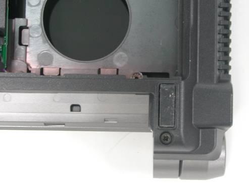
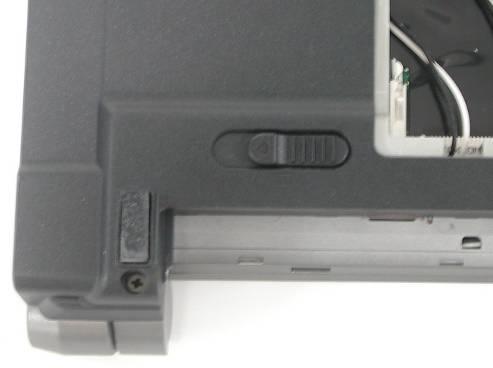
3 OPTICAL DRIVE Optical Drive Module Press latch here then pull it out. CPU CPU CPU Module The illustrations below show how to remove the CPU module from the notebook. Removing CPU 1. Remove 6 screws(m2*4l(k)) and take the Fan bracket away. 2. Disconnect the FAN connector and remove 2 screws(m2*4l(k)) then take away the Fan Module. M2*4L 3-3


4 3. Remove the 4 screws (M2*4L(K)) upon the thermal module and take away the CPU heat sink module gently 4. Turn the non-removable screw here 180 degrees counter-clockwise to loosen the CPU and take the CPU away Note: If thermal module has no thermal pad on it, please plus a thermal pad on the CPU die before assembling. 3-4


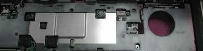
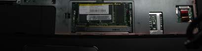
5 SECOND MEMORY MEMORY Second Memory Module The W3000A Series Notebook does not have onboard RAM. There are two SO-DIMM sockets for installing SO-DIMM RAM. It can upgrade the total memory size up to 2GB with a 1GB module on each socket. Removing Memory module 1. Pull 2 latches 2. Pop the module up to a 45 angles, and then pulling out the module in that angle. W IRELESS LAN W IRELESS Wireless LAN Module This slot usually has Wireless LAN module when leaving the factory, this slot is for optional system upgrade. Removing Wireless LAN Module 1. Remove 1 screw (M2*4L(K)), then take the mini-pci cover off. LAN 2. Remove 2 Antenna cables from Wireless LAN Module 3-5


6 3. Remove the Wireless LAN module by opening the 2 latches aside, which will pop the module up to an angle of 30, then pull out the module in that angle just like memory module. KEYBOARD K/B COVER Keyboard Module The illustration of below shows how to remove the keyboard Removing Keyboard and Keyboard Cover 1. Remove 2 screws (M2*4L(K)) 2. Unlock 3 keyboard latches then pull out the keyboard forward and lay the keyboard on the front side then disconnect the FPC. 3-6


) and FPC on top case and take")
7 FIRST MEMORY First Memory Module 1. The first memory module is under keyboard. Push the memory cover to the left side and lift the memory cover and open the two latches to pop up memory module at 45 degrees angle then pull it out. LCD LCD Module The illustrations below show how to remove and disassemble the LCD module. The module contains LCD panel, Inverter board, LCD Hinge bracket, Hinge cover, LCD front cover, LCD back cover 1. Remove 2 screws(m2*4l(k)) and FPC on top case and take away the Keyboard Cover. 2. Remove Coaxial cable and inverter cable 3-7


8 3. Remove Antenna and switch cable. 4. Remove 2 screws(m2*8l(k)) on bottom case M2*8L 5. Remove 2 screws(m2*8l(k)) on both ends 3-8


9 M2*8L 6. Take away the LCD Module LCD Removing LCD Module 1. Remove 5 rubber pads and 5 screws(m2 x 4L) from LCD module. 2. Prying the inside edges of the top front bezel, then separate it from LCD back cover and take 3-9

)")

)")
10 LCD front bezel away. 3. Disconnect both inverter cable. 4. Remove 1 screws (M2*4L(K)) and 2 screws (M2*3L(K)) take Inverter board off. LCD 5. Remove 8 screws(m2*4l(k)) and take the LCD panel off. DISASSEMBLY 3-10

) on the")

11 M2*4L 6. Remove 2 tapes and dissconnect coaxial cable then take it away. 7. Finally, Remove 4 screws(m2*3l(k)) on the right LCD bracket, and 4 screws on the ilft side to disassemble LCD brackets. M2*3L M2*3L 8. Remove 1 screw(m2*4l(k)) and take the swtich board off. 3-11
) on")


)and take")
12 9. Secure 1 screw(m2*4l(k)) on left and right side hing,then take right and left hinge off. 10. Take away the Power button. 11. Remove 2 screws (M2*4L(K))and take away both antennas 3-12


) on the top")
 on the")
13 TOP CASE Removing Top Case Module 1. Disconnect All FPC on top case. REMOVE 2. Remove 8 screws (M2*4L(K)) on the top case and 8 screws (M2*4L(K) on the bottom case. M2*4L M2*4L 3-13


) then take")
14 3. Separate the top case module from the bottom case module. 4. Remove 4 screws(m2*4l(k)) and take away both speaker. 5. Disconnect touch pad FPC cables and remove 5 screws(m2*3l(k)) then take touch pad backet off and take touch pad away. 3-14


) and take away the Motherboard")
15 6. Remove 6 scews (M2*2L(K)) and take away both side key modules MOTHERBOARD MDC Motherboard module The illustrations below show how to disassemble and remove the Motherboard module, the blue tooth module and the modem module. Removing Motherboard Module 1. Disconnect the power cable 2. Remove 3 screws (M2*4L(K)) and take away the Motherboard Module from the left side. 3-15


16 M2*4L 3. Turn the mother board around, remove 2 screws (M2*4L(K)), disconnect the modem cable. M2*4L 4. Remove the blue tooth module. 3-16


17 5. Remove 2 screws (M2*8L(K))and remove the ODD connector M2*8L 6. Remove the power cable and 1 screw to remove the DC-in jack board. 3-17
Disassembly Procedure
 Chapter 2 Disassembly Procedure Please follow the information provided in this section to perform the complete disassembly procedure of the notebook. Be sure to use proper tools described before. SUS A7T
Disassembly Procedure
 Chapter 3 Disassembly Procedure Please follow the information provided in this section to perform the complete disassembly procedure of the notebook. Be sure to use proper tools described before. A SUS
Upgrade & Replacement
 Chapter 4 Upgrade & Replacement Follow the individual procedures in this chapter to perform the notebook s upgrade and replacement of various major components. A sus A7V Series Notebook is an all-in-one
ASUS A2000 Series Notebook consists of various modules. This chapter
 Chapter 2 Disassembly Procedure Please follow the information provided in this section to perform the complete disassembly procedure of the notebook. Be sure to use proper tools described before. ASUS
Installation & Replacement
 Chapter 5 Installation & Replacement Follow the individual procedures to perform the notebook s installation and replacement of various major components. Series Notebook balances novelty and mobility in
Upgrade & Replacement
 Chapter 4 Upgrade & Replacement Follow the individual procedures in this chapter to perform the notebook s upgrade and replacement of various major components. Z84Jc Series Notebook is a 2 spindles product,
Disassembly Procedure
 Chapter 2 Disassembly Procedure Please follow the information provided in this section to perform the complete disassembly procedure of the notebook. Be sure to use proper tools described before. A SUS
Installation & Replacement
 Installation & Replacement Follow the individual procedures to perform the notebook s installation and replacement of various major components. Z70N Series Notebook is a fusion of flexibility, style and
Upgrade & Replacement
 Chapter 5 Upgrade & Replacement Follow the individual procedures in this chapter to perform the notebook s upgrade and replacement of various major components. A sus A6000U Series Notebook is a 2 spindles
Disassembly Procedure
 Chapter 2 Disassembly Procedure Please follow the information provided in this section to perform the complete disassembly procedure of the notebook. Be sure to use proper tools described before. A SUS
Disassembly Procedure
 Chapter 3 Disassembly Procedure Please follow the information provided in this section to perform the complete disassembly procedure of the notebook. Be sure to use proper tools described before. ASUS
KN1Series Notebook consists of various modules. This chapter describes
 Chapter 2 Disassembly Procedure Please follow the information provided in this section to perform the complete disassembly procedure of the notebook. Be sure to use proper tools described before. KNSeries
Disassembly Procedure
 Chapter 2 Disassembly Procedure Please follow the information provided in this section to perform the complete disassembly procedure of the Eee PC 1201HA. Be sure to use proper tools described before.
Installation & Replacement
 Chapter 5 Installation & Replacement Follow the individual procedures to perform the notebook s installation and replacement of various major components. Series Notebook balances novelty and mobility in
Assembly Procedure. Chapter
 Chapter 3 Assembly Procedure Please follow the information provided in this section to perform the complete assembly procedure of the Eee PC 1101HA. Be sure to use proper tools described before. A fter
Table of contents. VGN-FSxx series Disassemble Instruction. Section Title Page
 VGN-FSxx series Instruction Table of contents Section Title Page 1 Disassembly Procedures Outline Fixture for disassembly 2 Disassembly procedure flow chart 3 2 Disassembly components Disassembly battery
Assembly Procedure. Chapter
 PROCEDURE Chapter 1 Assembly Procedure Please follow the information provided in this section to perform the complete assembly procedure of the notebook. Be sure to use proper tools described before. After
Disassembly Manual Version 1.1
 EasyNote K5 Disassembly Manual Version 1.1 Required Tools Disassembly Instructions DIP Switch Setting Reassembly Instructions Required Tools ll EasyNote K5 maintenance procedures can be performed using
TravelMate 6493 Series Disassembly Instruction
 TravelMate 6493 Series Disassembly Instruction please refer to http://csd.acer.com.tw PRINTED IN TAIWAN Chapter 3 Machine Disassembly and Replacement This chapter contains step-by-step procedures on how
Sabio Digital SD-KN1 Notebook Assembly Guide
 Sabio Digital SD-KN1 Notebook Assembly Guide Rev. 1.4 Sabio Digital KN1 Assembly Guide 1 of 11 www.sabioproducts.com Table of Contents Section 1.0 - Overview... 3 Section 2.0 - Before You Begin... 3 Section
Installation & Replacement
 Installation & Replacement Follow the individual procedures to perform the notebook s installation and replacement of various major components. Z31N Series Notebook balances novelty and mobility in an
GT735(MS-1721)Disassemble SOP
Disassemble SOP") 1 Battery Pack 2 BOTTOM DOOR ASSY 3 THERMAL-KIT And CPU Module 4 RAM TUNER And WLAN Module 5 HDD Module ASSY 6 ODD Module ASSY 7 HINGE COVER ASSY 8 UPPER CASE ASSY 9 LOWER CASE ASSY 10 LCD MODULE ASSY
1 Battery Pack 2 BOTTOM DOOR ASSY 3 THERMAL-KIT And CPU Module 4 RAM TUNER And WLAN Module 5 HDD Module ASSY 6 ODD Module ASSY 7 HINGE COVER ASSY 8 UPPER CASE ASSY 9 LOWER CASE ASSY 10 LCD MODULE ASSY
FIELD REPLACEABLE UNIT DOCUMENTATION. Satellite TM. A20 Series GENERAL INFORMATION. Tools Required for Proper Disassembly and Reassembly:
 GENERAL INFORMATION Tools Required for Proper Disassembly and Reassembly: 1. Phillips Screwdriver (Size 0&1) 2. 4mm Flat head Screwdriver 3. Case Separator 4. ESD Wrist Strap 5. ESD mats 6. Tweezers Before
GX720 (MS-1722)Disassemble SOP
Disassemble SOP") GX720 (MS-1722)Disassemble SOP 1 Battery Pack 2 BOTTOM DOOR ASSY 3 THERMAL-KIT And CPU Module 4 RAM WLAN And TUNER Module 5 HDD Module ASSY 6 ODD Module ASSY 7 HINGE COVER ASSY 8 UP CASE ASSY 9 LOWER CASE
GX720 (MS-1722)Disassemble SOP 1 Battery Pack 2 BOTTOM DOOR ASSY 3 THERMAL-KIT And CPU Module 4 RAM WLAN And TUNER Module 5 HDD Module ASSY 6 ODD Module ASSY 7 HINGE COVER ASSY 8 UP CASE ASSY 9 LOWER CASE
Dell Inspiron XPS and Inspiron 9100 Service Manual
 Dell Inspiron XPS and Inspiron 9100 Service Manual Dell Inspiron XPS and Inspiron 9100 Service Manual Before You Begin Memory Module, Mini PCI Card, and Devices System Components Subwoofer Bluetooth Card
Installation & Replacement
 Installation & Replacement Follow the individual procedures to perform the notebook s installation and replacement of various major components. Z30N Series Notebook balances novelty and mobility in an
FIELD REPLACEABLE UNIT DOCUMENTATION. Satellite Pro TM Series GENERAL INFORMATION. Tools Required for Proper Disassembly and Reassembly:
 GENERAL INFORMATION Tools Required for Proper Disassembly and Reassembly: 1. Phillips Screwdriver (Size 0&1) 2. Flat head Screwdriver 3. Security Torx (Size 7) 4. Case Separator 5. ESD Wrist Strap 6. ESD
ww.battery-adapter.com
 Removing and replacing an FRU Lenovo G470/G475/G570/G575 This section presents exploded figures with the instructions to indicate how to remove and replace the FRU. Make sure to observe the following general
Satellite Pro TM Series GENERAL INFORMATION. Disassembly and Reassembly:
 GENERAL INFORMATION Disassembly and Reassembly: 1. Phillips Screwdriver (Size 0&1) 2. Flat head Screwdriver 3. Case Separator 4. ESD Wrist Strap 5. ESD mats 6. Tweezers Before attempting any of the following
Packard Bell. EasyNote BU Series. Disassembly Guide
 Packard Bell EasyNote BU Series Disassembly Guide Table of Contents Overview...3 Technician Notes...3 Disassembly Instructions...3 Reassembly Instructions...3 Required Tools...3 Battery...4 Memory...4
Easy Note Alpha Disassembly. Required Tools Disassembly Instructions Reassembly Instructions
 Easy Note Alpha Disassembly Required Tools Disassembly Instructions Reassembly Instructions Required Tools All Easy Note Alpha maintenance procedures can be performed using the following tools: Tweezers
Thank you for purchasing this Factory Service Manual CD/DVD from servicemanuals4u.com.
 Thank you for purchasing this Factory Service Manual CD/DVD from servicemanuals4u.com. Please check out our ebay auctions for more great deals on Factory Service Manuals: servicemanuals4u Dell Inspiron
WEASEL N/B MAINTENANCE
 2. System Assembly & Disassembly 2.1 System View 2.1.1 Front View ❶ Microphone Connector ❷ Audio Input Connector ❸ Audio Output Connector ❹ Top Cover Latch ❹ ❶ ❸ ❷ 2.1.2 Left-Side View ❶ VGA Port ❷ S-Video
EX310 (MS-1333)Disassemble SOP
Disassemble SOP") EX310 (MS-1333)Disassemble SOP 1 Battery Pack 2 BOTTOM DOOR ASSY 3 WLAN THERMAL-KIT And CPU Module 4 MDC And RAM Module 5 HDD Module ASSY 6 ODD Module ASSY 7 HINGE COVER ASSY 8 UP CASE ASSY 9 LOWER CASE
EX310 (MS-1333)Disassemble SOP 1 Battery Pack 2 BOTTOM DOOR ASSY 3 WLAN THERMAL-KIT And CPU Module 4 MDC And RAM Module 5 HDD Module ASSY 6 ODD Module ASSY 7 HINGE COVER ASSY 8 UP CASE ASSY 9 LOWER CASE
Disassembly Manual T19
 Disassembly Manual T19 version change by date 0.1 Copied text from written notes DE 18-10-2005 0.2 Added photos & corrected layout DE 19-10-2005 Page 1 of 15 Battery & Dummy Cards 1. Remove the Battery.
Figure 4-29 Removing the CPU compartment cover
 4 Replacement Procedures 4.9 CPU 4 4.9 CPU Removing the CPU To remove the CPU, follow the steps below. 1. Turn the computer upside down and remove two M2.5 4 security screws securing the CPU compartment
Dell Inspiron System Board
 Dell Inspiron 17-5749 System Board Replacement This guide will instruct users on the procedure of removing/replacing the Dell Inspiron 17-5749 system board. Written By: Christopher Tran ifixit CC BY-NC-SA
Service Manual (LS40, LS50) LG Electronics
 LG Electronics") Service Manual (LS40, LS50) LG Electronics 00 Battery Pack. Push the battery latch in the direction shown below; then slide the battery pack out of the slot. 00 Hard Disk Drive Remove the battery pack
Service Manual (LS40, LS50) LG Electronics 00 Battery Pack. Push the battery latch in the direction shown below; then slide the battery pack out of the slot. 00 Hard Disk Drive Remove the battery pack
Written By: John Sutton
 Replacing the fan on your HP g7-2275 dx. Written By: John Sutton ifixit CC BY-NC-SA www.ifixit.com Page 1 of 20 INTRODUCTION Laptop cooking your lap? This guide will walk you through replacing your fan.
PR601 (MS-163K)Disassemble SOP
Disassemble SOP") PR601 (MS-163K)Disassemble SOP 1 Battery Pack 2 BOTTOM DOOR ASSY 3 THERMAL-KIT And CPU Module 4 RAM WLAN MDC and BT Module 5 HDD Module ASSY 6 ODD Module ASSY 7 HINGE COVER ASSY 8 UP CASE ASSY 9 LOWER
PR601 (MS-163K)Disassemble SOP 1 Battery Pack 2 BOTTOM DOOR ASSY 3 THERMAL-KIT And CPU Module 4 RAM WLAN MDC and BT Module 5 HDD Module ASSY 6 ODD Module ASSY 7 HINGE COVER ASSY 8 UP CASE ASSY 9 LOWER
Packard Bell. EasyNote BG Series. Disassembly Guide
 Packard Bell EasyNote BG Series Disassembly Guide Table of Contents Overview...3 Technician Notes...3 Disassembly Instructions...3 Reassembly Instructions...3 Required Tools...3 Battery...4 Hard Disk...4
Le Disassembly. Required Tools Disassembly Instructions Reassembly Instructions
 Le Div@ Disassembly Required Tools Disassembly Instructions Reassembly Instructions Required Tools All Le Div@ maintenance procedures can be performed using the following tools: Tweezers Small flat-head
Thank you for purchasing this Factory Service Manual CD/DVD from servicemanuals4u.com.
 Thank you for purchasing this Factory Service Manual CD/DVD from servicemanuals4u.com. Please check out our ebay auctions for more great deals on Factory Service Manuals: servicemanuals4u Dell Latitude
Installation Guide. Copyright 2005 MSI Computer Corp.
 Installation Guide Copyright 2005 MSI Computer Corp. Overview: 1013 is shipped out as a barebone. Some of the components are equipped while some are not. This installation guide provides you with the information
FIELD REPLACEABLE UNIT DOCUMENTATION. Portege R100 GENERAL INFORMATION. Tools Required for Proper Disassembly and Reassembly:
 Portege TM GENERAL INFORMATION Tools Required for Proper Disassembly and Reassembly: 1. Phillips Screwdriver (Size 0) 2. Flat head Screwdriver 3. Case Separator 4. ESD Wrist Strap 5. ESD mat 6. Tweezers
Assembly Instructions: ASUS* Z62F
 Processor 1. Ensure there is no power source connected to the notebook and remove battery pack. (See Fig.1) Fig.1 Removing the Thermal Solution: 1. Remove the panel located on the underside of the notebook,
Dell Inspiron Optical-Drive Connector
 Dell Inspiron 17-5749 Optical-Drive Connector Board Replacement This guide will instruct users on the procedure of removing/replacing the Dell Inspiron 17-5749 optical-drive connector board. Written By:
GX620 (MS-1651)Disassemble SOP
Disassemble SOP") GX620 (MS-1651)Disassemble SOP 1 Battery Pack 2 BOTTOM DOOR ASSY 3 THERMAL-KIT And CPU Module 4 RAM WLAN And TUNER Module 5 HDD Module ASSY 6 ODD Module ASSY 7 HINGE COVER ASSY 8 UP CASE ASSY 9 LOWER CASE
GX620 (MS-1651)Disassemble SOP 1 Battery Pack 2 BOTTOM DOOR ASSY 3 THERMAL-KIT And CPU Module 4 RAM WLAN And TUNER Module 5 HDD Module ASSY 6 ODD Module ASSY 7 HINGE COVER ASSY 8 UP CASE ASSY 9 LOWER CASE
Removing and Replacing Parts
 Removing and Replacing Parts Preparing to Work Inside the Computer Recommended Tools Screw Identification System Components Hard Drive Fixed Optical Drive Media Bay Devices Memory Modules Mini PCI Card
4.1 General. 4 Replacement Procedures
 4.1 General This chapter explains how to disassemble the computer and replace Field Replaceable Units (FRUs). It may not be necessary to remove all the FRUs in order to replace one. The chart below is
Chapter 4 Replacement Procedures
 Chapter 4 Replacement Procedures 4 4-ii Satellite P30 Series Maintenance Manual Chapter 4 Contents 4.1 General... 4-1 4.2 Battery... 4-7 4.3 PC Card... 4-8 4.4 HDD... 4-10 4.5 Optical Drive Module... 4-12
Dell Inspiron Mini 10 RAM Replacement
 Upgrade or replace RAM to boost speed and performance. Written By: Danielle Jarecki ifixit CC BY-NC-SA www.ifixit.com Page 1 of 12 INTRODUCTION This guide will give step-by-step instructions on how to
Disassembly Instruction LIFEBOOK E733
 Disassembly Instruction LIFEBOOK E733 Contents Notes on installing and removing boards and components 2 Mandatory Support Bulletins 3 Removing the battery 4 Removing the ODD 5 Removing the memory modules
LifeBook P7120D Assembly
 LifeBook P7120D Assembly ESD Precautions are required when working on this LifeBook computer. 1. Connect the left microphone cable to the microphone PCB. 2. Insert them both into the rear cover of the
FIELD REPLACEABLE UNIT DOCUMENTATION
 Satellite TM 1700 Series GENERAL INFORMATION Tools Required for Proper Disassembly and Reassembly: 1. Phillips Screwdriver (Size 1) 2. Flat head screwdriver (5mm) 3. Hex driver (5mm) 4. Case Separator
Written By: Patrick. Disassembly to clean dust from the fan and heat sink. HP Pavilion G6 disassembly for cleaning
 HP Pavilion G6 disassembly for cleaning Disassembly to clean dust from the fan and heat sink. Written By: Patrick ifixit CC BY-NC-SA www.ifixit.com Page 1 of 11 INTRODUCTION Disassembly to clean dust from
GX630 (MS-1652)Disassemble SOP
Disassemble SOP") GX630 (MS-1652)Disassemble SOP 1 Battery Pack 2 BOTTOM DOOR ASSY 3 THERMAL-KIT And CPU Module 4 RAM WLAN And TUNER Module 5 HDD Module ASSY 6 ODD Module ASSY 7 HINGE COVER ASSY 8 UP CASE ASSY 9 LOWER CASE
GX630 (MS-1652)Disassemble SOP 1 Battery Pack 2 BOTTOM DOOR ASSY 3 THERMAL-KIT And CPU Module 4 RAM WLAN And TUNER Module 5 HDD Module ASSY 6 ODD Module ASSY 7 HINGE COVER ASSY 8 UP CASE ASSY 9 LOWER CASE
Dell Latitude E6500 Teardown
 Dell Latitude E6500 Teardown Disassembling the Dell Latitude E6500. Step by Step. I disassemble it down to the base assembly. Written By: Luis Gomez ifixit CC BY-NC-SA www.ifixit.com Page 1 of 16 INTRODUCTION
PowerBook G4 Aluminum 12" GHz Display Data Cable Replacement
 PowerBook G4 Aluminum 12" 1-1.5 GHz Display Data Cable Replacement Written By: Matthew Newsom ifixit CC BY-NC-SA www.ifixit.com Page 1 of 47 INTRODUCTION Replace a damaged display data cable to restore
Dell Latitude C800 Service Manual
 Dell Latitude C800 Service Manual Dell Latitude C800 Service Manual Before You Begin Preparing to Work Inside the Computer Recommended Tools Screw Identification Removing and Replacing Parts System Components
PowerBook G4 Aluminum 12" GHz Left Clutch Hinge Replacement
 PowerBook G4 Aluminum 12" 1-1.5 GHz Left Clutch Hinge Replacement Written By: Matthew Newsom ifixit CC BY-NC-SA www.ifixit.com Page 1 of 50 INTRODUCTION Replace a broken clutch hinge to make your display
Written By: Patrick Robichaud
 Complete teardown of the Lenovo T61p (very similar to the T60/T61/T60p) right down to the bare motherboard and LCD screen. Specs: C2D T7700 2.4 GHz 2 GB DDR2 RAM 80 GB SATA HDD 15.6" 1920x1200 LCD Written
CX420 (MS-1453) Disassemble Guide
 Disassemble Guide") CX420 (MS-1453) Disassemble Guide 1 BATTERY PACK 2 BOTTOM DOOR ASSY 3 HDD MODULE 4 ODD MODULE 5 THERMAL-KIT CPU DRAM 6 KEYBOARD 7 SEPARATE UPPER CASE AND LOWER CASE 8 LOWER CASE ASSY 9 UPPER CASE ASSY
CX420 (MS-1453) Disassemble Guide 1 BATTERY PACK 2 BOTTOM DOOR ASSY 3 HDD MODULE 4 ODD MODULE 5 THERMAL-KIT CPU DRAM 6 KEYBOARD 7 SEPARATE UPPER CASE AND LOWER CASE 8 LOWER CASE ASSY 9 UPPER CASE ASSY
Thank you for purchasing this Factory Service Manual CD/DVD from servicemanuals4u.com.
 Thank you for purchasing this Factory Service Manual CD/DVD from servicemanuals4u.com. Please check out our ebay auctions for more great deals on Factory Service Manuals: servicemanuals4u Dell Inspiron
Chapter 4 Replacement Procedures
 Chapter 4 Replacement Procedures 4 Replacement Procedures 4 4-ii Satellite R10 Maintenance Manual (960-509) 4 Replacement Procedures Chapter 4 Contents 4.1 Overview... 4-1 Safety Precautions... 4-2 Before
Dell XPS M1730 Service Manual
 Dell XPS M1730 Service Manual Model PP06XA www.dell.com support.dell.com Notes, Notices, and Cautions NOTE: A NOTE indicates important information that helps you make better use of your computer. NOTICE:
Dell Latitude C800 SERVICE MANUAL. support.dell.com
 Dell Latitude C800 SERVICE MANUAL www.dell.com support.dell.com Dell Latitude C800 SERVICE MANUAL www.dell.com support.dell.com Notes, Notices, and Cautions NOTE: A NOTE indicates important information
Dell Inspiron N5110 Service Manual
 Dell Inspiron N5110 Service Manual Regulatory model: P17F Regulatory type: P17F001 Notes, Cautions, and Warnings NOTE: A NOTE indicates important information that helps you make better use of your computer.
Product End-of-Life Disassembly Instructions
 Product End-of-Life Disassembly Instructions Product Category: Personal Computers Marketing Name / Model [List multiple models if applicable.] HP Compaq 8200 Elite USDT Business PC Name / Model #2 Name
Toshiba Satellite L305-S5946 Power Jack Replacement
 Toshiba Satellite L305-S5946 Power Jack Replacement Replace the power jack in your Toshiba Satellite L305-S5946. Written By: Michael Erberich ifixit CC BY-NC-SA www.ifixit.com Page 1 of 16 INTRODUCTION
PowerBook G4 Aluminum 15" GHz Heat Sink Replacement
 PowerBook G4 Aluminum 15" 1-1.5 GHz Heat Sink Replacement Written By: irobot ifixit CC BY-NC-SA www.ifixit.com Page 1 of 23 INTRODUCTION The heat sink helps keep the processor cool and happy. TOOLS: Anti-Static
HP G disassembly for cleaning and
 HP G62-453 disassembly for cleaning and thermal paste This is maintenance of an HP G62 series laptop. Written By: Bo Herrmannsen ifixit CC BY-NC-SA www.ifixit.com Page 1 of 12 INTRODUCTION Hi everyone,
Dell Latitude V710/V740 Service Manual
 Dell Latitude V710/V740 Service Manual Dell Latitude V710/V740 Service Manual Before You Begin Preparing to Work Inside the Computer Recommended Tools Computer Orientation Screw Identification System Components
X500 Parts Replacement Instructions
 X500 Parts Replacement Instructions This document is intended for service personnel. It provides information not found in the user manual. For information such as replacing the battery pack, hard disk
MacBook Pro 17" Models A1151 A1212 A1229 and A1261 Display Inverter Replacement
 MacBook Pro 17" Models A1151 A1212 A1229 and A1261 Display Inverter Replacement Written By: Andrew Bookholt ifixit CC BY-NC-SA www.ifixit.com Page 1 of 17 INTRODUCTION Backlight not working? Use this guide
HP Pavilion dv7-6c90us Cooling fan Replacement
 HP Pavilion dv7-6c90us Cooling fan Replacement This guide will walk you through the process of replacing the cooling fan in an HP Pavilion dv7 laptop. Written By: Angelina Clayton ifixit CC BY-NC-SA www.ifixit.com
How to disassemble Toshiba Satellite T135, T135D, T130, T130D laptop base.
 How to disassemble Toshiba Satellite T135, T135D, T130, T130D laptop base. In this guide I show how to disassemble a Toshiba Satellite T135 laptop base. All laptop disassembly steps should be very similar
TravelMate 280 Exploded Diagram. www MK-Electronic de. Chapter 6 125
 TravelMate 280 Exploded Diagram Chapter 6 125 Cables LCD COAXIAL CABLE 15 XGA CABLE LCD COAXIAL 15 XGA 7 LAUNCH BOARD CABLE CABLE LAUNCH BOARD S50 INVERTER CABLE CABLE LED & INVERTER POWER CORD 125V 3PIN
Thank you for purchasing this Factory Service Manual CD/DVD from servicemanuals4u.com.
 Thank you for purchasing this Factory Service Manual CD/DVD from servicemanuals4u.com. Please check out our ebay auctions for more great deals on Factory Service Manuals: servicemanuals4u Dell Inspiron
Dell XPS M1530 Service Manual
 Dell XPS M1530 Service Manual Model PP28L www.dell.com support.dell.com Notes, Notices, and Cautions NOTE: A NOTE indicates important information that helps you make better use of your computer. NOTICE:
Dell Inspiron 1525 Upper Case Replacement
 Dell Inspiron 1525 Upper Case Replacement Replace the upper case on a Dell Inspiron 1525. Written By: Miroslav Djuric ifixit CC BY-NC-SA www.ifixit.com Page 1 of 13 INTRODUCTION Use this guide to help
Dell XPS L702X Service Manual
 Dell XPS L702X Service Manual Regulatory model: P09E series Regulatory type: P09E002 Notes, Cautions, and Warnings NOTE: A NOTE indicates important information that helps you make better use of your computer.
Sony Vaio VPCCW21FX System Board Removal
 Sony Vaio VPCCWFX System Board Removal General motherhood : Standard rules apply regarding static electricity discharge Keep track of screws that are removed by labeling each group and writing on the internal
The Fone Works. Written By: The Foneworks. This a teardown guide of the PlayStation 3. PlayStation 3 Motherboard Teardown
 The Fone Works PlayStation 3 Motherboard Teardown This a teardown guide of the PlayStation 3. Written By: The Foneworks 2017 thefoneworks.dozuki.com Page 1 of 23 INTRODUCTION This is a teardown guide based
PowerBook G4 Aluminum 12" GHz Logic Board Replacement
 PowerBook G4 Aluminum 12" 1-1.5 GHz Logic Board Replacement Written By: irobot ifixit CC BY-NC-SA www.ifixit.com Page 1 of 32 INTRODUCTION This motherboard includes all ports except the DC-In board. TOOLS:
S E R V I C E N O T E
 IINFORMATIION ONLY S E R V I C E N O T E Supersedes: MSO8104A-05 MSO8104A Digitizing Oscilloscope Serial Numbers: MY00000000-MY46001900 SG00000000-SG46001900 The original scopes motherboard is no longer
Scritto Da: Ben Hirsch
 HP Pavilion dv6000 Motherboard Replacement Replace the motherboard in your HP Pavilion dv6000. Scritto Da: Ben Hirsch ifixit CC BY-NC-SA it.ifixit.com Pagina 1 di 13 INTRODUZIONE How to replace/install
Dell Inspiron Battery-Connector Board
 Dell Inspiron 17-5749 Battery-Connector Board Replacement This guide will instruct users on the procedure of removing/replacing the Dell Inspiron 17-5749 battery-connector board. Written By: Christopher
Inspiron 22. Service Manual Series. Regulatory Model: W17B Regulatory Type: W17B001
 Inspiron 22 3000 Series Service Manual Regulatory Model: W17B Regulatory Type: W17B001 Notes, cautions, and warnings NOTE: A NOTE indicates important information that helps you make better use of your
Acer Aspire 5742 Screen Assembly
 Acer Aspire 5742 Screen Assembly Replacement Written By: Philip Le Riche ifixit CC BY-NC-SA www.ifixit.com Page 1 of 16 INTRODUCTION If your screen is cracked or non-functional you have two options: You
To connect the AC adapter:
 Replacing the AC Adapter Replacing the AC Adapter 3 Plug the power cord into a wall outlet. The power indicator turns on. To connect the AC adapter: Connect the power cord to the AC adapter. Power indicator
Toshiba Satellite A210 Motherboard
 Toshiba Satellite A210 Motherboard Replacement In this guide you will learn how to properly remove the Motherboard. Written By: Devin ifixit CC BY-NC-SA www.ifixit.com Page 1 of 12 INTRODUCTION Before
Thank you for purchasing this Factory Service Manual CD/DVD from servicemanuals4u.com.
 Thank you for purchasing this Factory Service Manual CD/DVD from servicemanuals4u.com. Please check out our ebay auctions for more great deals on Factory Service Manuals: servicemanuals4u Dell Inspiron
imac Intel 21.5" Retina 4K Display (2017) RAM
 RAM") imac Intel 21.5" Retina 4K Display (2017) RAM Replacement Learn how to replace or upgrade the RAM in your 2017 Retina 4K imac. Written By: Evan Noronha ifixit CC BY-NC-SA www.ifixit.com Page 1 of 38 INTRODUCTION
imac Intel 21.5" Retina 4K Display (2017) RAM Replacement Learn how to replace or upgrade the RAM in your 2017 Retina 4K imac. Written By: Evan Noronha ifixit CC BY-NC-SA www.ifixit.com Page 1 of 38 INTRODUCTION
Written By: Colin Glaves
 Written By: Colin Glaves ifixit CC BY-NC-SA www.ifixit.com Page 1 of 9 INTRODUCTION Please try our Troubleshooting Guide prior to replacing your Display Assembly. This guide covers the detachment and assembly
imac Intel 20" EMC 2133 and 2210 Optical Drive Data Cable Replacement
 imac Intel 20" EMC 2133 and 2210 Optical Drive Data Cable Replacement Scritto Da: Walter Galan ifixit CC BY-NC-SA it.ifixit.com Pagina 1 di 24 INTRODUZIONE Replace a broken optical drive data cable to
Written By: Walter Galan
 Mac Pro Late 2013 CPU Replacement Replace the CPU in your Mac Pro Late 2013. Written By: Walter Galan ifixit CC BY-NC-SA www.ifixit.com Page 1 of 17 INTRODUCTION Use this guide to replace the CPU. Removing
ibook G4 14" 933 MHz-1.33 GHz Hard Drive
 ibook G4 14" 933 MHz-1.33 GHz Hard Drive Replacement Written By: irobot ifixit CC BY-NC-SA www.ifixit.com Page 1 of 25 INTRODUCTION You can install hard drives up to 9.5mm thick. TOOLS: Coin (1) Phillips
imac Intel 20" EMC 2105 and 2118 SSD
 imac Intel 20" EMC 2105 and 2118 SSD Installation Replace the hard drive in your imac Intel 20" EMC 2105 and 2118. Written By: Dozuki System 2017 guides.crucial.com Page 1 of 15 INTRODUCTION Upgrade your
PowerBook G4 Aluminum 17" GHz Heat Sink & Fan Assembly Replacement
 PowerBook G4 Aluminum 17" 1-1.67 GHz Heat Sink & Fan Assembly Replacement Written By: irobot ifixit CC BY-NC-SA www.ifixit.com Page 1 of 26 INTRODUCTION The heat sink and fan together help to keep the