TravelMate 6493 Series Disassembly Instruction
|
|
|
- Samuel Lambert
- 5 years ago
- Views:
Transcription
1 TravelMate 6493 Series Disassembly Instruction please refer to PRINTED IN TAIWAN
2 Chapter 3 Machine Disassembly and Replacement This chapter contains step-by-step procedures on how to disassemble the notebook computer for maintenance and troubleshooting. Disassembly Requirements To disassemble the computer, you need the following tools: Wrist grounding strap and conductive mat for preventing electrostatic discharge Flat screwdriver Philips screwdriver Plastic flat screwdriver Plastic tweezers NOTE: The screws for the different components vary in size. During the disassembly process, group the screws with the corresponding components to avoid mismatch when putting back the components. 1

3 General Information Pre-disassembly Instructions Before proceeding with the disassembly procedure, make sure that you do the following: 1. Turn off the power to the system and all peripherals. 2. Unplug the AC adapter and all power and signal cables from the system. 3. Place the system on a flat, stable surface. 4. the battery pack. Disassembly Process The disassembly process is divided into the following stages: External module disassembly Main unit disassembly LCD module disassembly The flowcharts provided in the succeeding disassembly sections illustrate the entire disassembly sequence. Observe the order of the sequence to avoid damage to any of the hardware components. For example, if you want to remove the main board, you must first remove the keyboard, then disassemble the inside assembly frame in that order. Main Screw List 2
4 External Module Disassembly Process External Modules Disassembly Flowchart The flowchart below gives you a graphic representation on the entire disassembly sequence and instructs you on the components that need to be removed during servicing. For example, if you want to remove the main board, you must first remove the keyboard, then disassemble the inside assembly frame in that order. Turn off system and peripherals power Disconnect power and signal cables from system Battery Dummy Cards Lower Covers DIMMs 3G Card HDD ODD Screw List 3
, then slide out the battery pack from the main unit")
5 Removing the Battery Pack 1. Turn computer over. 2. Slide the battery lock/unlock latch to the unlock position. 3. Slide and hold the battery release latch to the release position (1), then slide out the battery pack from the main unit (2)


6 Removing the SD dummy card 1. Push the SD dummy card in to eject it. 2. Grasp the card and pull it out from the slot. 5


7 Removing the NewCard Dummy card 1. Push the NewCard eject button to eject it, then push it all the way in to eject the NewCard dummy. 2. Pull it out from the slot. 6
8 Removing the Lower Covers 1. See Removing the Battery Pack 2. See Removing the SD dummy card. 3. See Removing the NewCard Dummy card 4. Loosen the five captive screws in the Memory, HDD, and 3G bays as shown. 3G Cover Memory Cover HDD Cover 5. Carefully open the memory cover. 6. the HDD cover as shown. 7

9 7. the 3G cover as shown. 8


10 Removing the DIMM Modules 1. See Removing the Battery Pack. 2. the Memory Module cover See Removing the Lower Covers. 3. Push out the release latches on both sides of the DIMM socket to release the DIMM module. 4. the DIMM module. 5. Repeat steps for the second DIMM module. 9


11 Removing the 3G Module 1. See Removing the Battery Pack 2. the 3G cover. See Removing the Lower Covers. 3. Disconnect the antenna cables from the 3G board. 4. Move the antenna cables away and remove the two screws to release the 3G board. Step Size Quantity Screw Type 3G Module M2*3 2 10


12 5. Detach the 3G board from the 3G socket. Removing the Hard Disk Drive Module 1. See Removing the Battery Pack. 2. the HDD cover, See Removing the Lower Covers 3. Use the mylar tab to slide and lift up the hard disk drive module to remove. NOTE: To prevent damage to device, avoid pressing down on it or placing heavy objects on top of it. 11


13 4. the HDD holder by easing the sides outward to clear the carrier. 5. the four screws securing the hard disk to the carrier. Step Size Quantity Screw Type HDD Carrier M3* the HDD from the carrier. 12


14 Removing the Optical Drive Module 1. See Removing the Battery Pack. 2. the Memory cover. See Removing the Lower Covers. 3. Push the ODD release latch to eject the ODD module. 4. Pull the ODD module through the chassis to remove it from the main unit. 13


 M2*3 2 6.")

15 5. the four screws securing the ODD bracket and remove it from the ODD module. Step Size Quantity Screw Type ODD Bracket (red callout) M2*5 2 ODD Bracket (green callout) M2* the ODD board from the ODD module by disconnecting the interface as shown. 7. Insert a pin in the eject hole of the ODD to eject the ODD tray. 14


16 8. Press down on the locking catch to release the ODD cover and remove. 15
17 Main Unit Disassembly Process Main Unit Disassembly Flowchart External Modules before proceeding Switch Cover Keyboard ekey Board 3G Antenna WLAN Board Power Board WLAN Antenna LCD Module Upper Case Lower Case Card Reader TouchPad Bracket Speaker Module Bluetooth Module Modem Module Finger Print Reader Mainboard Thermal Module USB Board CPU Fan CPU Screw List 16


18 Removing the Switch Cover CAUTION: Using tools to remove the Switch Cover may cause damage to the outer casing. It is recommended that only fingers are used to remove the Switch Cover. 1. See Removing the Battery Pack 2. Locate and remove the two securing screws as shown. Step Size Quantity Screw Type Switch Cover M2* Turn the computer over and open the LCD module fully to expose the Switch Cover. IMPORTANT:The LCD module must be fully open in the horizontal position to remove the switch cover. 4. Lift the Switch Cover as shown, rightside first. 5. Lift the Switch Cover clear of the chassis. 17


19 Removing the Keyboard 1. See Removing the Battery Pack 2. See Removing the Switch Cover 3. Turn the computer over. the single securing screw as shown. Step Size Quantity Screw Type Keyboard M2* Turn the computer over. the two screws securing the keyboard to the upper case. Step Size Quantity Screw Type Keyboard M2*3 2 18


20 5. Lift the keyboard and turn it over to expose the FFC cables. 6. Release the keyboard FFC securing latch and disconnect the cable. 7. Release the Fine Track keyboard mouse FFC securing latch and disconnect the cable. 8. the keyboard from the chassis. 19


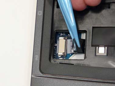
21 Removing the ekey Board 1. See Removing the Battery Pack. 2. See Removing the Keyboard 3. Disconnect the ekey Board cable from the mainboard. 4. the two securing screws from the ekey Board. Step Size Quantity Screw Type ekey Board M2*3 2 20


22 5. Carefully pull back the FFC to release the adhesive strips on the cable and remove the ekey Board from the upper case. 21


23 Removing the Power Board 1. See Removing the Battery Pack 2. See Removing the Keyboard 3. Disconnect the Power Board cable from the mainboard. 4. the two securing screws from the Power Board. Step Size Quantity Screw Type Power Board M2*3 2 22


24 5. Carefully pull back the FFC to release the adhesive strips on the cable and remove the Power Board from the upper case. 23


25 Removing the WLAN Module 1. See Removing the Keyboard 2. Disconnect the antenna cables from the WLAN module. 3. Move the antenna cables away and remove the two screws to release the WLAN module. Step Size Quantity Screw Type WLAN Module M2* Detach the WLAN Module from the mainboard. 24


26 Removing the 3G Antenna 1. See Removing the 3G Module. 2. the adhesive tape from the 3G cable as shown. 3. Gently pull the 3G cables through the chassis, as shown, until the cable terminals are free from the case. 25


27 Removing the WLAN Antenna and MIC Cable 1. Disconnect the MIC cable from the mainboard. 2. the MIC cable from the cable channel as shown. 3. the adhesive tape on the WLAN cable 26


28 4. the Antenna Cables from the housing well as shown. NOTE: Place the cables to one side to avoid damage. 5. Ensure all cables are free of the right side cable channel as shown. 27


29 Removing the LCD Module 1. the Battery Pack. See Removing the Battery Pack 2. the 3G Module. See Removing the 3G Module 3. the WLAN Module. See Removing the WLAN Module 4. the Antenna. See Removing the 3G Antenna 5. the two securing screws from the bottom of the chassis. Step Size Quantity Screw Type LCD Module M2* Turn the computer over. Disconnect the LCD cable from the top cover. 28
 connecting the LCD module.")
 M2*10 2 LCD")

30 7. the four securing screws (two on each side) connecting the LCD module. Step Size Quantity Screw Type LCD Module (red callout) M2*10 2 LCD Module (green callout) M2* Carefully remove the LCD module from the chassis. 29

31 Removing the Upper Cover 1. See Removing the Battery Pack 2. See Removing the LCD Module 3. Turn the computer over. the sixteen screws on the bottom panel. Step Size Quantity Screw Type Upper Cover (red callout) M2*10 10 Upper Cover (green callout) M2*4 6 30


32 4. Turn the computer over and disconnect the four cables from the mainboard as shown. A D C B Disconnect A as shown. Pull back the securing latch and disconnect B as shown. Pull back the securing latch and disconnect C as shown. Pull back the securing latch and disconnect D as shown. 31


33 5. the single screw on the top panel. Step Size Quantity Screw Type Upper Cover M2.5* Lift the upper cover off the chassis, top edge first, as shown. 7. Moving from top to bottom, pry off the upper cover as shown. 32


34 Removing the Card Reader Module 1. See Removing the Upper Cover 2. Turn the Upper Cover over. the single securing screw from the Card Reader. Step Size Quantity Screw Type Card Reader Module M2* Slide the module in the direction shown to clear the securing clips. 4. Lift the module and carefully remove the FFC cable from the adhesive pads, as shown, to remove the module. 33


35 Removing the Finger Print Reader 1. See Removing the Upper Cover 2. the securing screw from the Finger Print Reader bracket. Step Size Quantity Screw Type Finger Print Reader M2* the bracket from the Upper Cover. IMPORTANT:Do not discard the bracket. and replace on the new Finger Print Board. 34


36 4. Lift up the adhesive pad holding the Finger Print Board in place and ensure the FFC is free of the Upper Cover. 5. the Finger Print Reader, top edge first, from the Upper Cover. 35


37 Removing the TouchPad Bracket 1. See Removing the Finger Print Reader 2. the two securing screws from the bracket. Step Size Quantity Screw Type Touch Pad Bracket M2* Lift the FFC locking latch as shown. 4. the TouchPad FFC from the Upper Cover. 36

38 5. Rotate the TouchPad bracket upward as shown, and lift it clear of the Upper Cover. IMPORTANT:The TouchPad cannot be removed individually. To replace the TouchPad, replace the entire Upper Cover. 37

.")


39 Removing the Speaker Modules 1. See Removing the Upper Cover 2. the four securing screws (two from each module). Step Size Quantity Screw Type Speaker Module M2* Grasp the mylar cover and carefully pull back to expose the speaker cable. Pull the cable through the cover until it is completely free of obstructions. 4. the left and right speaker modules as shown. 38


40 Removing the Bluetooth Module 1. See Removing the Upper Cover 2. Disconnect the bluetooth cable from the mainboard as shown. 3. Using both hands, remove the Bluetooth module from the chassis. 4. Disconnect the cable from the Bluetooth module. 39


41 Removing the Modem Module 1. See Removing the Upper Cover 2. Disconnect the cable from the mainboard as shown. 3. Disconnect the cable from the RJ-11 port. 4. Detach the adhesive pad on the modem cable as shown. 40


42 5. Disconnect the cable from the Modem module. 6. the two securing screws from the Modem module. Step Size Quantity Screw Type Modem Module M2* the Modem from the mainboard. 41


43 Removing the Mainboard 1. See Removing the LCD Module. 2. See Removing the Upper Cover. 3. See Removing the Modem Module 4. the single securing screw from the mainboard. Step Size Quantity Screw Type Mainboard M2.5* Disconnect the mainboard from the USB Board by lifting the top-right corner of the mainboard away from the chassis as shown. 42


44 6. Pull out the left side of the casing to clear the I/O ports as shown. 7. Lift the mainboard rear edge first, as shown, and remove from the chassis. CAUTION: Ensure the I/O ports at the bottom of the mainboard are clear of the bottom base to prevent damage to the mainboard. 43


45 Removing the USB Board 1. the mainboard. See Removing the Mainboard. 2. the two securing screws from the USB board. Step Size Quantity Screw Type USB Board M2* Lift the USB board clear of the chassis. 44
")

46 Removing the Thermal Module 1. See Removing the Mainboard 2. the four securing screws (in reverse numerical order from screw 4 to screw 1) from the Thermal Module Step Size Quantity Screw Type Thermal Module M M 2.5D 3.2L K 6D NI Using both hands, lift the Thermal Module clear of the Mainboard. 45


47 Removing the CPU Fan 1. See Removing the Mainboard 2. Disconnect the fan cable from the mainboard. 3. the three securing screws from the CPU fan. Step Size Quantity Screw Type CPU Fan Module M2* Lift the fan clear of the mainboard. 46


48 Removing the CPU 1. See Removing the Thermal Module 2. Using a flat screwdriver, turn the CPU socket latch counter-clockwise 180 to release the CPU. 3. Lift the CPU clear of the Mainboard. 47
49 LCD Module Disassembly Process LCD Module Disassembly Flowchart LCD Panel from Main Unit before proceeding LCD Bezel Inverter Board Camera Module LCD Panel LCD FPC Cable LCD Brackets Antennas MIC Cable Screw List 48


50 Removing the LCD Bezel 1. the LCD module. See Removing the LCD Module 2. the two upper and two lower bezel screw caps. the four securing screws from the LCD module. Step Size Quantity Screw Type LCD Bezel M2.5* Lift up the bezel, left side first as shown followed by the bottom and right sides respectively. CAUTION: The LCD panel locking latches pass through the top of the bezel. Hold the lock in the open position to allow the latches to pass through the bezel when removing the top section. 49


51 Removing the Camera Module 1. the LCD Bezel. See Removing the LCD Bezel 2. Disconnect the Camera Module cable as shown. 3. Lift the Camera upward to detach the adhesive strip and remove the module from the LCD assembly. 50


52 Removing the Inverter Board 1. the LCD Bezel. See Removing the LCD Bezel 2. the single securing screw from the Inverter board as shown. Step Size Quantity Screw Type Inverter Board M2* Lift the Inverter clear of the LCD module and remove the left and right inverter cables from the module. 51


53 Removing the LCD Panel 1. See Removing the Inverter Board 2. the two securing screws from the panel as shown. Step Size Quantity Screw Type LCD Panel M2* Lift the LCD Panel clear of the LCD Module, taking care to ensure the cables are free from the back cover. 52


 from the LCD")
54 Removing the LCD Brackets and FPC Cable 1. the LCD panel. See Removing the LCD Panel 2. Turn the LCD panel over to expose the rear. Detach the camera cable from the LCD panel as shown. 3. Lift the adhesive strip as shown, and disconnect the LCD cable interface. 4. Grip the FPC cable and lift upward to detach the adhesive pads. 5. the eight securing screws (four on each side) from the LCD Panel brackets. the LCD brackets by pulling them away from the LCD Panel. Step Size Quantity Screw Type LCD Brackets M2*4 8 53


55 Removing the Antennas 1. See Removing the Battery Pack 2. See Removing the 3G Module 3. See Removing the WLAN Module 4. See Removing the LCD Panel 5. the strips holding the antenna cables in place. Ensure the cables are free from obstructions. 6. the left side antenna cable from the cable channel. 54


56 7. Detach the adhesive strips holding the antenna in place and remove the single securing screw. Step Size Quantity Screw Type WLAN Antenna M2* Lift the antenna away from the LCD module. 9. the right side antenna cable from the cable channel. 55


57 10. Detach the adhesive strip holding the antenna in place. 11. the single securing screw from the antenna. Step Size Quantity Screw Type WLAN Antenna M2* the antenna from the LCD module. 56


58 13. the 3G antenna cable from the cable channel. 14. the two securing screws from the 3G antenna as shown. Step Size Quantity Screw Type 3G Antenna M2* the 3G antenna from the LCD module as shown, and gently remove the adhesive strip. 57


59 Removing the MIC Module 1. the LCD panel. See Removing the LCD Panel 2. the strip holding the MIC Module cable in place. Ensure the cable is free from obstructions. 3. the MIC cable and Module from the LCD module. 58
WEASEL N/B MAINTENANCE
 2. System Assembly & Disassembly 2.1 System View 2.1.1 Front View ❶ Microphone Connector ❷ Audio Input Connector ❸ Audio Output Connector ❹ Top Cover Latch ❹ ❶ ❸ ❷ 2.1.2 Left-Side View ❶ VGA Port ❷ S-Video
Disassembly Procedure
 Chapter 3 Disassembly Procedure Please follow the information provided in this section to perform the complete disassembly procedure of the notebook. Be sure to use proper tools described before. A SUS
Disassembly Procedure
 Chapter 2 Disassembly Procedure Please follow the information provided in this section to perform the complete disassembly procedure of the notebook. Be sure to use proper tools described before. A SUS
Disassembly Procedure
 Chapter 2 Disassembly Procedure Please follow the information provided in this section to perform the complete disassembly procedure of the notebook. Be sure to use proper tools described before. SUS A7T
FIELD REPLACEABLE UNIT DOCUMENTATION. Satellite TM. A20 Series GENERAL INFORMATION. Tools Required for Proper Disassembly and Reassembly:
 GENERAL INFORMATION Tools Required for Proper Disassembly and Reassembly: 1. Phillips Screwdriver (Size 0&1) 2. 4mm Flat head Screwdriver 3. Case Separator 4. ESD Wrist Strap 5. ESD mats 6. Tweezers Before
FIELD REPLACEABLE UNIT DOCUMENTATION. Satellite Pro TM Series GENERAL INFORMATION. Tools Required for Proper Disassembly and Reassembly:
 GENERAL INFORMATION Tools Required for Proper Disassembly and Reassembly: 1. Phillips Screwdriver (Size 0&1) 2. Flat head Screwdriver 3. Security Torx (Size 7) 4. Case Separator 5. ESD Wrist Strap 6. ESD
Disassembly Procedure
 Chapter 2 Disassembly Procedure Please follow the information provided in this section to perform the complete disassembly procedure of the notebook. Be sure to use proper tools described before. A SUS
Figure 4-29 Removing the CPU compartment cover
 4 Replacement Procedures 4.9 CPU 4 4.9 CPU Removing the CPU To remove the CPU, follow the steps below. 1. Turn the computer upside down and remove two M2.5 4 security screws securing the CPU compartment
Disassembly Procedure
 Chapter 2 Disassembly Procedure Please follow the information provided in this section to perform the complete disassembly procedure of the Eee PC 1201HA. Be sure to use proper tools described before.
Satellite Pro TM Series GENERAL INFORMATION. Disassembly and Reassembly:
 GENERAL INFORMATION Disassembly and Reassembly: 1. Phillips Screwdriver (Size 0&1) 2. Flat head Screwdriver 3. Case Separator 4. ESD Wrist Strap 5. ESD mats 6. Tweezers Before attempting any of the following
Disassembly Manual Version 1.1
 EasyNote K5 Disassembly Manual Version 1.1 Required Tools Disassembly Instructions DIP Switch Setting Reassembly Instructions Required Tools ll EasyNote K5 maintenance procedures can be performed using
FIELD REPLACEABLE UNIT DOCUMENTATION
 Satellite TM 1700 Series GENERAL INFORMATION Tools Required for Proper Disassembly and Reassembly: 1. Phillips Screwdriver (Size 1) 2. Flat head screwdriver (5mm) 3. Hex driver (5mm) 4. Case Separator
ww.battery-adapter.com
 Removing and replacing an FRU Lenovo G470/G475/G570/G575 This section presents exploded figures with the instructions to indicate how to remove and replace the FRU. Make sure to observe the following general
ASUS A2000 Series Notebook consists of various modules. This chapter
 Chapter 2 Disassembly Procedure Please follow the information provided in this section to perform the complete disassembly procedure of the notebook. Be sure to use proper tools described before. ASUS
Sabio Digital SD-KN1 Notebook Assembly Guide
 Sabio Digital SD-KN1 Notebook Assembly Guide Rev. 1.4 Sabio Digital KN1 Assembly Guide 1 of 11 www.sabioproducts.com Table of Contents Section 1.0 - Overview... 3 Section 2.0 - Before You Begin... 3 Section
Dell Inspiron N5110 Service Manual
 Dell Inspiron N5110 Service Manual Regulatory model: P17F Regulatory type: P17F001 Notes, Cautions, and Warnings NOTE: A NOTE indicates important information that helps you make better use of your computer.
Assembly Procedure. Chapter
 Chapter 3 Assembly Procedure Please follow the information provided in this section to perform the complete assembly procedure of the Eee PC 1101HA. Be sure to use proper tools described before. A fter
4.1 General. 4 Replacement Procedures
 4.1 General This chapter explains how to disassemble the computer and replace Field Replaceable Units (FRUs). It may not be necessary to remove all the FRUs in order to replace one. The chart below is
Chapter 4 Replacement Procedures
 Chapter 4 Replacement Procedures 4 4-ii Satellite P30 Series Maintenance Manual Chapter 4 Contents 4.1 General... 4-1 4.2 Battery... 4-7 4.3 PC Card... 4-8 4.4 HDD... 4-10 4.5 Optical Drive Module... 4-12
C202SA: Disassembly Guide
 ASUS Computer International C202SA: Disassembly Guide PN: 90NX00Y2-M00040 PN: 90NX00Y2-M00050 IMPORTANT NOTICE: This document is intended for ASUS Authorized Service Providers only. Performing any repairs
Disassembly Procedure
 Chapter 3 Disassembly Procedure Please follow the information provided in this section to perform the complete disassembly procedure of the notebook. Be sure to use proper tools described before. A SUS
Dell XPS L702X Service Manual
 Dell XPS L702X Service Manual Regulatory model: P09E series Regulatory type: P09E002 Notes, Cautions, and Warnings NOTE: A NOTE indicates important information that helps you make better use of your computer.
Dell Inspiron XPS and Inspiron 9100 Service Manual
 Dell Inspiron XPS and Inspiron 9100 Service Manual Dell Inspiron XPS and Inspiron 9100 Service Manual Before You Begin Memory Module, Mini PCI Card, and Devices System Components Subwoofer Bluetooth Card
Installation & Replacement
 Installation & Replacement Follow the individual procedures to perform the notebook s installation and replacement of various major components. Z70N Series Notebook is a fusion of flexibility, style and
Dell Inspiron 1525 Upper Case Replacement
 Dell Inspiron 1525 Upper Case Replacement Replace the upper case on a Dell Inspiron 1525. Written By: Miroslav Djuric ifixit CC BY-NC-SA www.ifixit.com Page 1 of 13 INTRODUCTION Use this guide to help
Easy Note Alpha Disassembly. Required Tools Disassembly Instructions Reassembly Instructions
 Easy Note Alpha Disassembly Required Tools Disassembly Instructions Reassembly Instructions Required Tools All Easy Note Alpha maintenance procedures can be performed using the following tools: Tweezers
Installation Guide. Copyright 2005 MSI Computer Corp.
 Installation Guide Copyright 2005 MSI Computer Corp. Overview: 1013 is shipped out as a barebone. Some of the components are equipped while some are not. This installation guide provides you with the information
FIELD REPLACEABLE UNIT DOCUMENTATION. Portege R100 GENERAL INFORMATION. Tools Required for Proper Disassembly and Reassembly:
 Portege TM GENERAL INFORMATION Tools Required for Proper Disassembly and Reassembly: 1. Phillips Screwdriver (Size 0) 2. Flat head Screwdriver 3. Case Separator 4. ESD Wrist Strap 5. ESD mat 6. Tweezers
Dell Inspiron System Board
 Dell Inspiron 17-5749 System Board Replacement This guide will instruct users on the procedure of removing/replacing the Dell Inspiron 17-5749 system board. Written By: Christopher Tran ifixit CC BY-NC-SA
Upgrade & Replacement
 Chapter 4 Upgrade & Replacement Follow the individual procedures in this chapter to perform the notebook s upgrade and replacement of various major components. A sus A7V Series Notebook is an all-in-one
Dell XPS M1530 Service Manual
 Dell XPS M1530 Service Manual Model PP28L www.dell.com support.dell.com Notes, Notices, and Cautions NOTE: A NOTE indicates important information that helps you make better use of your computer. NOTICE:
To connect the AC adapter:
 Replacing the AC Adapter Replacing the AC Adapter 3 Plug the power cord into a wall outlet. The power indicator turns on. To connect the AC adapter: Connect the power cord to the AC adapter. Power indicator
Packard Bell. EasyNote BU Series. Disassembly Guide
 Packard Bell EasyNote BU Series Disassembly Guide Table of Contents Overview...3 Technician Notes...3 Disassembly Instructions...3 Reassembly Instructions...3 Required Tools...3 Battery...4 Memory...4
Disassembly Instruction LIFEBOOK E733
 Disassembly Instruction LIFEBOOK E733 Contents Notes on installing and removing boards and components 2 Mandatory Support Bulletins 3 Removing the battery 4 Removing the ODD 5 Removing the memory modules
Dell XPS M1730 Service Manual
 Dell XPS M1730 Service Manual Model PP06XA www.dell.com support.dell.com Notes, Notices, and Cautions NOTE: A NOTE indicates important information that helps you make better use of your computer. NOTICE:
Dell Inspiron Optical-Drive Connector
 Dell Inspiron 17-5749 Optical-Drive Connector Board Replacement This guide will instruct users on the procedure of removing/replacing the Dell Inspiron 17-5749 optical-drive connector board. Written By:
Upgrade & Replacement
 Chapter 4 Upgrade & Replacement Follow the individual procedures in this chapter to perform the notebook s upgrade and replacement of various major components. Z84Jc Series Notebook is a 2 spindles product,
Dell Precision M4600 Owner's Manual
 Dell Precision M4600 Owner's Manual Regulatory Model P13F Regulatory Type P13F001 Notes, Cautions, and Warnings NOTE: A NOTE indicates important information that helps you make better use of your computer.
Disassembly Procedure
 Chapter 3 Disassembly Procedure Please follow the information provided in this section to perform the complete disassembly procedure of the notebook. Be sure to use proper tools described before. ASUS
Dell Inspiron Mini 10 RAM Replacement
 Upgrade or replace RAM to boost speed and performance. Written By: Danielle Jarecki ifixit CC BY-NC-SA www.ifixit.com Page 1 of 12 INTRODUCTION This guide will give step-by-step instructions on how to
Written By: John Sutton
 Replacing the fan on your HP g7-2275 dx. Written By: John Sutton ifixit CC BY-NC-SA www.ifixit.com Page 1 of 20 INTRODUCTION Laptop cooking your lap? This guide will walk you through replacing your fan.
Latitude Owner's Manual. Regulatory Model: P72G Regulatory Type: P72G003
 Latitude 5495 Owner's Manual Regulatory Model: P72G Regulatory Type: P72G003 Notes, cautions, and warnings NOTE: A NOTE indicates important information that helps you make better use of your product. CAUTION:
Thank you for purchasing this Factory Service Manual CD/DVD from servicemanuals4u.com.
 Thank you for purchasing this Factory Service Manual CD/DVD from servicemanuals4u.com. Please check out our ebay auctions for more great deals on Factory Service Manuals: servicemanuals4u Dell Inspiron
MacBook Pro 15" Core Duo Model A1150 LCD Panel High Definition (1920x1200) Replacement
 Replacement") MacBook Pro 15" Core Duo Model A1150 LCD Panel High Definition (1920x1200) Replacement Written By: Ben Eisenman ifixit CC BY-NC-SA www.ifixit.com Page 1 of 25 INTRODUCTION By following this guide, you
MacBook Pro 15" Core Duo Model A1150 LCD Panel High Definition (1920x1200) Replacement Written By: Ben Eisenman ifixit CC BY-NC-SA www.ifixit.com Page 1 of 25 INTRODUCTION By following this guide, you
Table of Contents - 1. Predator PO3-600 User s Guide
 Table of Contents - 1 Predator PO3-600 User s Guide 2 - Upgrading your Computer 2018. All Rights Reserved. Desktop Computer Covers: Tower models This revision: April 2018 V1.00 Important This manual contains
X500 Parts Replacement Instructions
 X500 Parts Replacement Instructions This document is intended for service personnel. It provides information not found in the user manual. For information such as replacing the battery pack, hard disk
Toshiba Satellite L305-S5946 Power Jack Replacement
 Toshiba Satellite L305-S5946 Power Jack Replacement Replace the power jack in your Toshiba Satellite L305-S5946. Written By: Michael Erberich ifixit CC BY-NC-SA www.ifixit.com Page 1 of 16 INTRODUCTION
Disassembly Manual T19
 Disassembly Manual T19 version change by date 0.1 Copied text from written notes DE 18-10-2005 0.2 Added photos & corrected layout DE 19-10-2005 Page 1 of 15 Battery & Dummy Cards 1. Remove the Battery.
Thank you for purchasing this Factory Service Manual CD/DVD from servicemanuals4u.com.
 Thank you for purchasing this Factory Service Manual CD/DVD from servicemanuals4u.com. Please check out our ebay auctions for more great deals on Factory Service Manuals: servicemanuals4u Dell Inspiron
Written By: Colin Glaves
 Written By: Colin Glaves ifixit CC BY-NC-SA www.ifixit.com Page 1 of 9 INTRODUCTION Please try our Troubleshooting Guide prior to replacing your Display Assembly. This guide covers the detachment and assembly
Thank you for purchasing this Factory Service Manual CD/DVD from servicemanuals4u.com.
 Thank you for purchasing this Factory Service Manual CD/DVD from servicemanuals4u.com. Please check out our ebay auctions for more great deals on Factory Service Manuals: servicemanuals4u Dell Latitude
FIELD REPLACEABLE UNIT DOCUMENTATION. Portege Series GENERAL INFORMATION
 FIELD REPLACEABLE UNIT DOCUMENTATION TM Portege GENERAL INFORMATION For Parts listing use TOSHFAX Doc: 3440CT(PP344C-2PU82): #7219 3480CT(PP348C-4PU82): #7228 Before attempting any of the following procedures,
Dell XPS 14z Owner s Manual
 Dell XPS 14z Owner s Manual Computer model: L412z Regulatory model: P24G series Regulatory type: P24G001 Notes, Cautions, and Warnings NOTE: A NOTE indicates important information that helps you make better
Manual 04 - Logic Board
 Manual 04 - Logic Board Written By: Josh Patterson 2017 guides.cellphonesandbox.com Page 1 of 16 TOOLS: Technician Starter Package (1) 2017 guides.cellphonesandbox.com Page 2 of 16 Step 1 Removal 1 - Battery
Alienware Area-51 R5 Service Manual
 Alienware Area-51 R5 Service Manual Computer Model: Alienware Area-51 R5 Regulatory Model: D03X Regulatory Type: D03X002 Notes, cautions, and warnings NOTE: A NOTE indicates important information that
Le Disassembly. Required Tools Disassembly Instructions Reassembly Instructions
 Le Div@ Disassembly Required Tools Disassembly Instructions Reassembly Instructions Required Tools All Le Div@ maintenance procedures can be performed using the following tools: Tweezers Small flat-head
Toshiba Satellite A105-S4011 Touchpad
 Toshiba Satellite A105-S4011 Touchpad Replacement This guide will instruct you on how to remove the current touchpad from this laptop and how to reinstall another. This is a straightforward process and
PowerBook G3 Pismo I/O EMI Shield Replacement
 PowerBook G3 Pismo I/O EMI Shield Replacement Written By: irobot ifixit CC BY-NC-SA www.ifixit.com Page 1 of 23 INTRODUCTION A thin metal shield resides above the ports that protects from electromagnetic
Packard Bell. EasyNote BG Series. Disassembly Guide
 Packard Bell EasyNote BG Series Disassembly Guide Table of Contents Overview...3 Technician Notes...3 Disassembly Instructions...3 Reassembly Instructions...3 Required Tools...3 Battery...4 Hard Disk...4
apple Service Source ibook G4 (14.1 LCD) October 22, Apple Computer, Inc. All rights reserved.
 October 22, Apple Computer, Inc. All rights reserved.") apple Service Source ibook G4 (14.1 LCD) October 22, 2003 2003 Apple Computer, Inc. All rights reserved. apple Service Source Take Apart ibook G4 (14.1 LCD) 2003 Apple Computer, Inc. All rights reserved.
apple Service Source ibook G4 (14.1 LCD) October 22, 2003 2003 Apple Computer, Inc. All rights reserved. apple Service Source Take Apart ibook G4 (14.1 LCD) 2003 Apple Computer, Inc. All rights reserved.
Veriton M678G/S678G. Product End-of-Life Disassembly Guide
 Veriton M678G/S678G Product End-of-Life Disassembly Guide Machine Disassembly and Replacement To disassemble the computer, you need the following tools: Wrist grounding strap and conductive mat for preventing
KN1Series Notebook consists of various modules. This chapter describes
 Chapter 2 Disassembly Procedure Please follow the information provided in this section to perform the complete disassembly procedure of the notebook. Be sure to use proper tools described before. KNSeries
Dell Inspiron Battery-Connector Board
 Dell Inspiron 17-5749 Battery-Connector Board Replacement This guide will instruct users on the procedure of removing/replacing the Dell Inspiron 17-5749 battery-connector board. Written By: Christopher
Assembly Instructions: ASUS* Z62F
 Processor 1. Ensure there is no power source connected to the notebook and remove battery pack. (See Fig.1) Fig.1 Removing the Thermal Solution: 1. Remove the panel located on the underside of the notebook,
Motorola Moto X Motherboard Replacement
 Motorola Moto X Motherboard Replacement Replace the motherboard in a Motorola Moto X. Written By: Sam Lionheart ifixit CC BY-NC-SA www.ifixit.com Page 1 of 18 INTRODUCTION Use this guide to replace the
MacBook Core 2 Duo Clutch Cover
 MacBook Core 2 Duo Clutch Cover Replacement Replace the clutch cover on your MacBook Core 2 Duo. Written By: Ben Eisenman ifixit CC BY-NC-SA www.ifixit.com Page 1 of 29 INTRODUCTION Replace the curved
Inspiron 22. Service Manual Series. Regulatory Model: W17B Regulatory Type: W17B001
 Inspiron 22 3000 Series Service Manual Regulatory Model: W17B Regulatory Type: W17B001 Notes, cautions, and warnings NOTE: A NOTE indicates important information that helps you make better use of your
GT735(MS-1721)Disassemble SOP
Disassemble SOP") 1 Battery Pack 2 BOTTOM DOOR ASSY 3 THERMAL-KIT And CPU Module 4 RAM TUNER And WLAN Module 5 HDD Module ASSY 6 ODD Module ASSY 7 HINGE COVER ASSY 8 UPPER CASE ASSY 9 LOWER CASE ASSY 10 LCD MODULE ASSY
1 Battery Pack 2 BOTTOM DOOR ASSY 3 THERMAL-KIT And CPU Module 4 RAM TUNER And WLAN Module 5 HDD Module ASSY 6 ODD Module ASSY 7 HINGE COVER ASSY 8 UPPER CASE ASSY 9 LOWER CASE ASSY 10 LCD MODULE ASSY
Upgrade & Replacement
 Chapter 5 Upgrade & Replacement Follow the individual procedures in this chapter to perform the notebook s upgrade and replacement of various major components. A sus A6000U Series Notebook is a 2 spindles
Removing and Replacing Parts
 Removing and Replacing Parts Preparing to Work Inside the Computer Recommended Tools Screw Identification System Components Hard Drive Fixed Optical Drive Media Bay Devices Memory Modules Mini PCI Card
Inspiron Service Manual. 2-in-1. Computer Model: Inspiron Regulatory Model: P69G Regulatory Type: P69G001
 Inspiron 13 5000 2-in-1 Service Manual Computer Model: Inspiron 13-5378 Regulatory Model: P69G Regulatory Type: P69G001 Notes, cautions, and warnings NOTE: A NOTE indicates important information that helps
Installation & Replacement
 Chapter 5 Installation & Replacement Follow the individual procedures to perform the notebook s installation and replacement of various major components. Series Notebook balances novelty and mobility in
OLPC XO-4 Touch Mouse Buttons Controller Replacement
 OLPC XO-4 Touch Mouse Buttons Controller Replacement This guide will show you how to replace the mouse buttons controller. Written By: Michael Kellerman ifixit CC BY-NC-SA www.ifixit.com Page 1 of 12 INTRODUCTION
OLPC XO-4 Touch Touchpad Controller Replacement
 OLPC XO-4 Touch Touchpad Controller Replacement This guide will walk through replacing a touchpad. Written By: Theodore Tsanakas ifixit CC BY-NC-SA www.ifixit.com Page 1 of 13 INTRODUCTION Use this guide
GX720 (MS-1722)Disassemble SOP
Disassemble SOP") GX720 (MS-1722)Disassemble SOP 1 Battery Pack 2 BOTTOM DOOR ASSY 3 THERMAL-KIT And CPU Module 4 RAM WLAN And TUNER Module 5 HDD Module ASSY 6 ODD Module ASSY 7 HINGE COVER ASSY 8 UP CASE ASSY 9 LOWER CASE
GX720 (MS-1722)Disassemble SOP 1 Battery Pack 2 BOTTOM DOOR ASSY 3 THERMAL-KIT And CPU Module 4 RAM WLAN And TUNER Module 5 HDD Module ASSY 6 ODD Module ASSY 7 HINGE COVER ASSY 8 UP CASE ASSY 9 LOWER CASE
How to Upgrade the Hard Drive in a 24 imac (2007-Early 2009)
") Instructional Video Series How to Upgrade the Hard Drive in a 24 imac (2007-Early 2009) Skill Level: Involved Time to Complete: Approximately 45 Minutes Required Tools: Small Phillips Screwdriver Torx
Instructional Video Series How to Upgrade the Hard Drive in a 24 imac (2007-Early 2009) Skill Level: Involved Time to Complete: Approximately 45 Minutes Required Tools: Small Phillips Screwdriver Torx
Nintendo DSi Wi-Fi Antenna Board
 Nintendo DSi Wi-Fi Antenna Board Replacement Replace your Nintendo DSi's Wi-Fi antenna. Written By: Andrew Bookholt ifixit CC BY-NC-SA www.ifixit.com Page 1 of 16 INTRODUCTION Use this guide to replace
Presario 1200 Series Models: XL101-XL113, XL115, XL118-XL127. This section explains the removal and replacement procedures for the 1200XL unit.
 Removal Sequence Presario 1200 Series This section explains the removal and replacement procedures for the 1200XL unit. Serial Number Location Report the unit s serial number 1 to Compaq when requesting
Installation & Replacement
 Installation & Replacement Follow the individual procedures to perform the notebook s installation and replacement of various major components. Z31N Series Notebook balances novelty and mobility in an
HP Compaq 6730b Display Replacement
 Here is a HP Compaq 6730b with a cracked LCD after having been dropped. This is a straight forward repair. Written By: oldturkey03 ifixit CC BY-NC-SA www.ifixit.com Page 1 of 11 INTRODUCTION This laptop
XPS 15 2-in-1. Service Manual. Computer Model: XPS Regulatory Model: P73F Regulatory Type: P73F001
 XPS 15 2-in-1 Service Manual Computer Model: XPS 15-9575 Regulatory Model: P73F Regulatory Type: P73F001 Notes, cautions, and warnings NOTE: A NOTE indicates important information that helps you make better
Written By: Walter Galan
 imac Intel 17" Power Supply Replacement Written By: Walter Galan ifixit CC BY-NC-SA www.ifixit.com Page 1 of 18 INTRODUCTION Power hungry? Keep those electrons flowing by replacing your power supply. TOOLS:
imac Intel 21.5" EMC 2389 Stand Replacement
 imac Intel 21.5" EMC 2389 Stand Replacement Replace a broken or cosmetically unappealing stand on the imac 2389 21.5 Written By: Aaron Cooke ifixit CC BY-NC-SA www.ifixit.com Page 1 of 30 INTRODUCTION
Written By: Allie Menard
 Written By: Allie Menard ifixit CC BY-NC-SA www.ifixit.com Page 1 of 20 TOOLS: Paper Clip (1) Phillips #00 Screwdriver (1) Phillips #1 Screwdriver (1) Spudger (1) Tweezers (1) ifixit CC BY-NC-SA www.ifixit.com
Acer Aspire 7736Z-4809 LCD Module Replacement
 Acer Aspire 7736Z-4809 LCD Module Replacement The monitor does not work properly. Replacing the LCD module may solve this problem. Written By: Pnithan Jantarakolica ifixit CC BY-NC-SA www.ifixit.com Page
ALIENWARE AURORA SERVICE MANUAL 01/
 ALIENWARE AURORA SERVICE MANUAL 01/ 01 Notes, Cautions, and Warnings NOTE: A NOTE indicates important information that helps you make better use of your computer. CAUTION: A CAUTION indicates either potential
EX310 (MS-1333)Disassemble SOP
Disassemble SOP") EX310 (MS-1333)Disassemble SOP 1 Battery Pack 2 BOTTOM DOOR ASSY 3 WLAN THERMAL-KIT And CPU Module 4 MDC And RAM Module 5 HDD Module ASSY 6 ODD Module ASSY 7 HINGE COVER ASSY 8 UP CASE ASSY 9 LOWER CASE
EX310 (MS-1333)Disassemble SOP 1 Battery Pack 2 BOTTOM DOOR ASSY 3 WLAN THERMAL-KIT And CPU Module 4 MDC And RAM Module 5 HDD Module ASSY 6 ODD Module ASSY 7 HINGE COVER ASSY 8 UP CASE ASSY 9 LOWER CASE
Motorola Atrix 4G Bottom Speaker
 Motorola Atrix 4G Bottom Speaker Replacement This guide will show you how to access the Motorola Atrix 4Gs bottom speaker for repair or replacement. Written By: Jake ifixit CC BY-NC-SA www.ifixit.com Page
Dell Precision Owner's Manual. Regulatory Model: P60F Regulatory Type: P60F001
 Dell Precision 3520 Owner's Manual Regulatory Model: P60F Regulatory Type: P60F001 Notes, cautions, and warnings NOTE: A NOTE indicates important information that helps you make better use of your product.
MacBook Pro 17" Models A1151 A1212 A1229 and A1261 Display Inverter Replacement
 MacBook Pro 17" Models A1151 A1212 A1229 and A1261 Display Inverter Replacement Written By: Andrew Bookholt ifixit CC BY-NC-SA www.ifixit.com Page 1 of 17 INTRODUCTION Backlight not working? Use this guide
imac Intel 20" EMC 2133 and 2210 Optical Drive Data Cable Replacement
 imac Intel 20" EMC 2133 and 2210 Optical Drive Data Cable Replacement Scritto Da: Walter Galan ifixit CC BY-NC-SA it.ifixit.com Pagina 1 di 24 INTRODUZIONE Replace a broken optical drive data cable to
imac Intel 21.5" Retina 4K Display (2017) RAM
 RAM") imac Intel 21.5" Retina 4K Display (2017) RAM Replacement Learn how to replace or upgrade the RAM in your 2017 Retina 4K imac. Written By: Evan Noronha ifixit CC BY-NC-SA www.ifixit.com Page 1 of 38 INTRODUCTION
imac Intel 21.5" Retina 4K Display (2017) RAM Replacement Learn how to replace or upgrade the RAM in your 2017 Retina 4K imac. Written By: Evan Noronha ifixit CC BY-NC-SA www.ifixit.com Page 1 of 38 INTRODUCTION
H4 Series Hardware Replacement Guide
 Machine type: 10059/7723 10060/7724 10068/7752 10080/3099/1194 10091/2558/1196 H4 Series Hardware Replacement Guide Version 3.0 2011.08 31500379 Hardware Replacement Guide Copyright Lenovo 2011. All rights
Written By: Walter Galan
 imac Intel 21.5" EMC 2428 CPU Replacement Replace the CPU in your imac Intel 21.5" EMC 2428. Written By: Walter Galan ifixit CC BY-NC-SA www.ifixit.com Page 1 of 33 INTRODUCTION Use this guide to upgrade
Written By: Walter Galan
 Replace a cracked screen on your iphone 4S. Written By: Walter Galan ifixit CC BY-NC-SA www.ifixit.com Page 1 of 32 INTRODUCTION Use this guide to replace the screen on your iphone 4S. After successfully
PowerBook G4 Aluminum 12" GHz Display Data Cable Replacement
 PowerBook G4 Aluminum 12" 1-1.5 GHz Display Data Cable Replacement Written By: Matthew Newsom ifixit CC BY-NC-SA www.ifixit.com Page 1 of 47 INTRODUCTION Replace a damaged display data cable to restore
MacBook Pro 15" Core 2 Duo Model A1211 Speakers Replacement
 MacBook Pro 15" Core 2 Duo Model A1211 Speakers Replacement Written By: irobot ifixit CC BY-NC-SA www.ifixit.com Page 1 of 21 INTRODUCTION Restore sound to your laptop by replacing the speakers. TOOLS:
Mac mini Late 2014 Power Supply Replacement
 Mac mini Late 2014 Power Supply Replacement Replace the power supply in a Late 2014 Mac mini. Written By: Sam Lionheart ifixit CC BY-NC-SA www.ifixit.com Page 1 of 19 INTRODUCTION Use this guide to replace
imac Intel 27" EMC 2429 SSD Dual Drive
 imac Intel 27" EMC 2429 SSD Dual Drive Installation Install the dual hard drive kit in an imac Intel 27" EMC 2429. Written By: Dozuki System 2017 guides.crucial.com Page 1 of 22 INTRODUCTION This guide
apple Service Source imac (USB 2.0) Updated 11 September Apple Computer, Inc. All rights reserved.
 Updated 11 September Apple Computer, Inc. All rights reserved.") apple Service Source imac (USB 2.0) Updated 11 September 2003 2003 Apple Computer, Inc. All rights reserved. imac (USB 2.0) - 1 apple Service Source Basics imac (USB 2.0) 2003 Apple Computer, Inc. All
apple Service Source imac (USB 2.0) Updated 11 September 2003 2003 Apple Computer, Inc. All rights reserved. imac (USB 2.0) - 1 apple Service Source Basics imac (USB 2.0) 2003 Apple Computer, Inc. All