ASUS A2000 Series Notebook consists of various modules. This chapter
|
|
|
- Felicity Skinner
- 5 years ago
- Views:
Transcription
1 Chapter 2 Disassembly Procedure Please follow the information provided in this section to perform the complete disassembly procedure of the notebook. Be sure to use proper tools described before. ASUS A2000 Series Notebook consists of various modules. This chapter describes the procedures for the complete notebook disassembly. In addition, in between procedures, the detailed disassembly procedure of individual modules will be provided for your service needs. The disassembly procedure consists of the following steps: Battery Module Optical Driver Module HDD Module CPU Module Keyboard Module Memory Module Mini PCI Module VGA Module LCD Module Top Case Module Motherboard Module Bottom case Module 2-1

.")


2 BATTERY Battery Module The illustration below shows how to remove the battery module. 1. Turn the notebook over. Unlock and hold the latch, then remove the battery. OPTICAL DRIVE REMOVAL Optical Drive Module Remove 2 screws(m2*6l). Stick the tip a pair of tweezers in the screw hole, and hold it, then pull the optical driver out. HDD MODULE HDD MODULE REMOVAL HDD Module The illustrations below show how to remove the HDD module from the notebook. Removing HDD Module Remove 3 screws(m3*6l). Then pull out the HDD to take the HDD away. 2-2


.")


3 CPU MODULE REMOVAL CPU REMOVAL CPU Module The illustrations below show how to remove the CPU module from the notebook. Removing CPU 1. Remove 3 screws(m2*6l).remove CPU cover. 2. Remove 4 screws(m2*3l),then remove CPU bracket. 3. Remover 2 Mylar s here. Remove CPU Heat-sink module. 2-3


4 4. Open the CPU Socket s latch to loosen the CPU. Then use the CPU vacuum hand pump to suck up the CPU and lift the CPU away. Then close the CPU Socket s latch. KEYBOARD DISASSEMBLY Keyboard Module The illustration of below shows how to remove the keyboard. K/B COVER REMOVAL Removing Keyboard Cover Stick the tip of a small screwdriver in the tiny hole, and then slide the keyboard cover to the left side at the same time remove the keyboard cover. K/B REMOVAL Removing Keyboard Pull out the keyboard to the front side and then lay the keyboard on the front side. 2-4

. 2. Carefully pull out the keyboard cable (No. 5) with a pair or tweezers.")


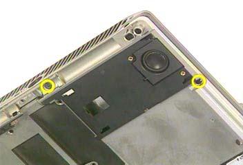
5 Disconnect the FPC cable with tweezers, then remover the keyboard. CABLE REMOVAL Removing Keyboard Cable 1. Use a flexible connector tool to unlock the cable connector on both ends (No. 4). 2. Carefully pull out the keyboard cable (No. 5) with a pair or tweezers. 3. Lock the connector (No. 6) again to avoid possible breakage. 4. Finally the keyboard plate can be removed from the notebook. 5. Cable out 4. Unlock 4. Unlock 6. Lock 6. Lock MEMORY MODULE Memory Module The illustration of below shows how to remove the Memory. REMOVAL MEMORY 1. Remove 2 copper foils. Remove 2 screws(m2*3l)(m2*13l). DISASSEMBL 2-5


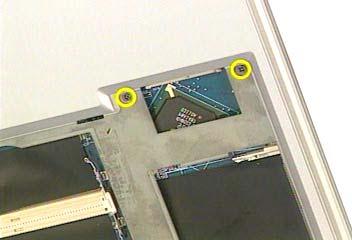
6 2. Then remove DDR DIMM Cover. Open the two latches to pop up the memory module. Then pull it out. WIRELESS LAN MODULE WIRELESS LAN REMOVAL Mini PCI Module This slot usually has Wireless LAN module when leaving the factory, this slot is for optional system upgrade. Removing Wireless LAN Module 1. Remove 1 copper foil. Remove 1 screw(m2*13l). 2. Then remove Mini PCI shielding bracket. Remove 1 yellow tape to loose a wireless antenna cable. 2-6


. 2.")


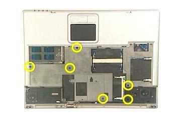
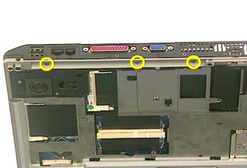
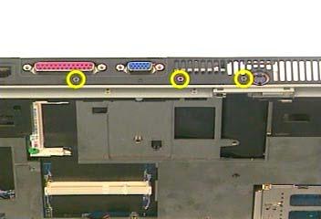
7 3. Disconnect main antenna and auxiliary antenna. Open the two latches to pop the Mini PCI module up then pull it out. VGA MODULE VGA Module 1. Remove 3 tapes to loose a wireless antenna cable. Remove 4 screws(m2*13l). 2. Then remove Top case bracket. Disconnet the harness cover with single-slotted screwdriver and then remove it. 3. Disconnect inverter cable and LCD coaxial cable. Open the two latches to pop up the VGA board then pull it out. 2-7


, And 3 screws")
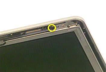
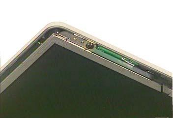
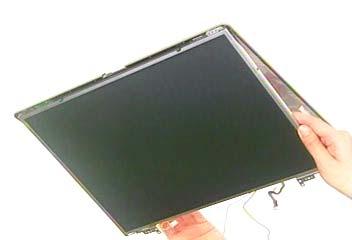
8 Coaxial cable Inverter cable LCD MODULE LCD REMOVAL LCD Module The illustrations below show how to remove and disassemble the LCD module. The module contains LCD panel, Inverter board, LCD Hinge bracket, Hinge cover, LCD front cover, and LCD back cover. Removing LCD Module Remove 1 screw(m2*6l).remove 3 screws(m2*6l), And 3 screws on the other side(m2*6l).carefully lift the LCD module up to separate the LCD module from the notebook. 2-8


9 LCD DISASSEMBLY Disassembling LCD Module 1. Remove 5 rubber pads and rubber low. Remove 5 screws(m2.5*6l)(m2*4l). 2. Carefully pry the inside edges have the LCD Cover Frame and Lift the LCD Cover Frame away from the LCD module. 3. Remove 1 tape. Remove inverter board form LCD Panel and disconnect LCD power cord form inverter board. 4. Remove 1 tape here. And 1 tape. Disconnect inverter cable from inverter board. 2-9


")
10 5. Remove 2 screws(m2.5*5l).and 2 screws on the other side(m2.5*5l) Remove 1 screw(m2*4l).and 1 screw on the other side(m2*4l) Separate Lcd panel form LCD cover. 2-10


.")


11 6. Remove hinge module here from LCD cover and on the other side. 7. Remove 1 screw(m2*4l). And remove hinge cover from hinge. 8. Remove 3 tapes. Loosen wireless main antenna from LCD back cover. And then loosen auxiliary antenna from LCD back cover. 2-11

. 10.")


12 9. Remove 4 screws(m2*3l). Then separate LCD bracket from LCD panel. Remove another 4 screws here on the other side(m2*3l). 10. Separate LCD bracket from LCD panel. Remove 1 tape here. Remove 1 tape here then disconnect coaxial cab. TOP CASE MODULE TOP CASE MODULE Top Case Module The illustrations below show how to disassemble and remove the top case module of the notebook. Removing Top Case Module 1. Remove 6 screws(m2*13l). Remove 3 Mylar. REMOVE 2-12
13 2. Remove 3 screws(m2*6l)and remove 2 screws(m2*6l). 3. Remove 2 screws(m2*3l)and remove 3 screws(m2*6l). 4. Remove 6 screws(m2*6l)remove 2 screws(m2*3l). 2-13


14 5. Remove 3 screws(m2*13l)remove 1 Mylar. Disconnect the touch pad FPC cable with tweezers. 6. Separate Top Case module form the bottom case module and turn the TOP case and place it on disassembly. Disconnect speaker cable and remove Top case module. 7. Remove 1 Mylar and remove 3 tapes here then loosen Speaker cable from Top case. Remove 2 screws(m2*3l)and 2 screws on the other side(m2*3l) Separate speakers form the top case module. 2-14
.")


.")
15 8. Remove 4 screws(m2*3l).and take touchpad bracket away. Remove 3 copper pieces here. Remove the touchpad. MOTHERBOARD MODULE Motherboard module The illustrations below show how to disassemble and remove the Motherboard module. 1. Remove 2 screws(m2*6l).then separate audio board from motherboard. 2-15


16 2. Remove 1 tape then loosen Speaker cable from audio board. Disconnect speaker cable from audio board. 3. Disconnect touchpad FPC cable from audio board. MDC MODULE REMOVAL Removing Modem Module 1. Loosen 1 tape. Remove 2 screws(m2*3l) 2. Lift modem module up then disconnect modem cable and take it away Remove 2 tapes. Then separate modem cable from motherboard. Remove 1 tape. 2-16


")
 2.")


17 MOTHERBOARD REMOVAL Removing Motherboard 1. Then separate fan cables from motherboard remove 5 screws(m2*8l) (M2*6L)(M2*6L)and 1 screw(m2*6l) 2. Lift the motherboard up a little bit and push aside the bottom case and separate motherboard module from the bottom case. 2-17


disconnect")
18 BOTTOM CASE MODULE Bottom Case Module The illustrations below show how to disassemble and remove the bottom case module of the notebook. 1. Remove AUDIO DJ button here on bottom case. 2. Remove 3 screws(m2*6l)disconnect thermal module on bottom case. 2-18
Disassembly Procedure
 Chapter 2 Disassembly Procedure Please follow the information provided in this section to perform the complete disassembly procedure of the notebook. Be sure to use proper tools described before. SUS A7T
Disassembly Procedure
 Chapter 3 Disassembly Procedure Please follow the information provided in this section to perform the complete disassembly procedure of the notebook. Be sure to use proper tools described before. A SUS
Disassembly Procedure
 Chapter 3 Disassembly Procedure Please follow the information provided in this section to perform the complete disassembly procedure of the notebook. Be sure to use proper tools described before. A SUS
Disassembly Procedure
 Chapter 2 Disassembly Procedure Please follow the information provided in this section to perform the complete disassembly procedure of the notebook. Be sure to use proper tools described before. A SUS
Disassembly Procedure
 Chapter 2 Disassembly Procedure Please follow the information provided in this section to perform the complete disassembly procedure of the notebook. Be sure to use proper tools described before. A SUS
Disassembly Procedure
 Chapter 3 Disassembly Procedure Please follow the information provided in this section to perform the complete disassembly procedure of the notebook. Be sure to use proper tools described before. ASUS
Upgrade & Replacement
 Chapter 4 Upgrade & Replacement Follow the individual procedures in this chapter to perform the notebook s upgrade and replacement of various major components. Z84Jc Series Notebook is a 2 spindles product,
Disassembly Procedure
 Chapter 2 Disassembly Procedure Please follow the information provided in this section to perform the complete disassembly procedure of the Eee PC 1201HA. Be sure to use proper tools described before.
Upgrade & Replacement
 Chapter 4 Upgrade & Replacement Follow the individual procedures in this chapter to perform the notebook s upgrade and replacement of various major components. A sus A7V Series Notebook is an all-in-one
Installation & Replacement
 Installation & Replacement Follow the individual procedures to perform the notebook s installation and replacement of various major components. Z70N Series Notebook is a fusion of flexibility, style and
Upgrade & Replacement
 Chapter 5 Upgrade & Replacement Follow the individual procedures in this chapter to perform the notebook s upgrade and replacement of various major components. A sus A6000U Series Notebook is a 2 spindles
Installation & Replacement
 Chapter 5 Installation & Replacement Follow the individual procedures to perform the notebook s installation and replacement of various major components. Series Notebook balances novelty and mobility in
Assembly Procedure. Chapter
 Chapter 3 Assembly Procedure Please follow the information provided in this section to perform the complete assembly procedure of the Eee PC 1101HA. Be sure to use proper tools described before. A fter
Disassembly Manual Version 1.1
 EasyNote K5 Disassembly Manual Version 1.1 Required Tools Disassembly Instructions DIP Switch Setting Reassembly Instructions Required Tools ll EasyNote K5 maintenance procedures can be performed using
KN1Series Notebook consists of various modules. This chapter describes
 Chapter 2 Disassembly Procedure Please follow the information provided in this section to perform the complete disassembly procedure of the notebook. Be sure to use proper tools described before. KNSeries
WEASEL N/B MAINTENANCE
 2. System Assembly & Disassembly 2.1 System View 2.1.1 Front View ❶ Microphone Connector ❷ Audio Input Connector ❸ Audio Output Connector ❹ Top Cover Latch ❹ ❶ ❸ ❷ 2.1.2 Left-Side View ❶ VGA Port ❷ S-Video
TravelMate 6493 Series Disassembly Instruction
 TravelMate 6493 Series Disassembly Instruction please refer to http://csd.acer.com.tw PRINTED IN TAIWAN Chapter 3 Machine Disassembly and Replacement This chapter contains step-by-step procedures on how
Figure 4-29 Removing the CPU compartment cover
 4 Replacement Procedures 4.9 CPU 4 4.9 CPU Removing the CPU To remove the CPU, follow the steps below. 1. Turn the computer upside down and remove two M2.5 4 security screws securing the CPU compartment
Sabio Digital SD-KN1 Notebook Assembly Guide
 Sabio Digital SD-KN1 Notebook Assembly Guide Rev. 1.4 Sabio Digital KN1 Assembly Guide 1 of 11 www.sabioproducts.com Table of Contents Section 1.0 - Overview... 3 Section 2.0 - Before You Begin... 3 Section
Packard Bell. EasyNote BU Series. Disassembly Guide
 Packard Bell EasyNote BU Series Disassembly Guide Table of Contents Overview...3 Technician Notes...3 Disassembly Instructions...3 Reassembly Instructions...3 Required Tools...3 Battery...4 Memory...4
FIELD REPLACEABLE UNIT DOCUMENTATION. Satellite TM. A20 Series GENERAL INFORMATION. Tools Required for Proper Disassembly and Reassembly:
 GENERAL INFORMATION Tools Required for Proper Disassembly and Reassembly: 1. Phillips Screwdriver (Size 0&1) 2. 4mm Flat head Screwdriver 3. Case Separator 4. ESD Wrist Strap 5. ESD mats 6. Tweezers Before
Easy Note Alpha Disassembly. Required Tools Disassembly Instructions Reassembly Instructions
 Easy Note Alpha Disassembly Required Tools Disassembly Instructions Reassembly Instructions Required Tools All Easy Note Alpha maintenance procedures can be performed using the following tools: Tweezers
Installation & Replacement
 Installation & Replacement Follow the individual procedures to perform the notebook s installation and replacement of various major components. Z31N Series Notebook balances novelty and mobility in an
Packard Bell. EasyNote BG Series. Disassembly Guide
 Packard Bell EasyNote BG Series Disassembly Guide Table of Contents Overview...3 Technician Notes...3 Disassembly Instructions...3 Reassembly Instructions...3 Required Tools...3 Battery...4 Hard Disk...4
Satellite Pro TM Series GENERAL INFORMATION. Disassembly and Reassembly:
 GENERAL INFORMATION Disassembly and Reassembly: 1. Phillips Screwdriver (Size 0&1) 2. Flat head Screwdriver 3. Case Separator 4. ESD Wrist Strap 5. ESD mats 6. Tweezers Before attempting any of the following
FIELD REPLACEABLE UNIT DOCUMENTATION
 Satellite TM 1700 Series GENERAL INFORMATION Tools Required for Proper Disassembly and Reassembly: 1. Phillips Screwdriver (Size 1) 2. Flat head screwdriver (5mm) 3. Hex driver (5mm) 4. Case Separator
FIELD REPLACEABLE UNIT DOCUMENTATION. Satellite Pro TM Series GENERAL INFORMATION. Tools Required for Proper Disassembly and Reassembly:
 GENERAL INFORMATION Tools Required for Proper Disassembly and Reassembly: 1. Phillips Screwdriver (Size 0&1) 2. Flat head Screwdriver 3. Security Torx (Size 7) 4. Case Separator 5. ESD Wrist Strap 6. ESD
FIELD REPLACEABLE UNIT DOCUMENTATION. Portege R100 GENERAL INFORMATION. Tools Required for Proper Disassembly and Reassembly:
 Portege TM GENERAL INFORMATION Tools Required for Proper Disassembly and Reassembly: 1. Phillips Screwdriver (Size 0) 2. Flat head Screwdriver 3. Case Separator 4. ESD Wrist Strap 5. ESD mat 6. Tweezers
Installation & Replacement
 Chapter 5 Installation & Replacement Follow the individual procedures to perform the notebook s installation and replacement of various major components. Series Notebook balances novelty and mobility in
Table of contents. VGN-FSxx series Disassemble Instruction. Section Title Page
 VGN-FSxx series Instruction Table of contents Section Title Page 1 Disassembly Procedures Outline Fixture for disassembly 2 Disassembly procedure flow chart 3 2 Disassembly components Disassembly battery
Written By: John Sutton
 Replacing the fan on your HP g7-2275 dx. Written By: John Sutton ifixit CC BY-NC-SA www.ifixit.com Page 1 of 20 INTRODUCTION Laptop cooking your lap? This guide will walk you through replacing your fan.
Assembly Procedure. Chapter
 PROCEDURE Chapter 1 Assembly Procedure Please follow the information provided in this section to perform the complete assembly procedure of the notebook. Be sure to use proper tools described before. After
Chapter 4 Replacement Procedures
 Chapter 4 Replacement Procedures 4 4-ii Satellite P30 Series Maintenance Manual Chapter 4 Contents 4.1 General... 4-1 4.2 Battery... 4-7 4.3 PC Card... 4-8 4.4 HDD... 4-10 4.5 Optical Drive Module... 4-12
Dell Inspiron Mini 10 RAM Replacement
 Upgrade or replace RAM to boost speed and performance. Written By: Danielle Jarecki ifixit CC BY-NC-SA www.ifixit.com Page 1 of 12 INTRODUCTION This guide will give step-by-step instructions on how to
ww.battery-adapter.com
 Removing and replacing an FRU Lenovo G470/G475/G570/G575 This section presents exploded figures with the instructions to indicate how to remove and replace the FRU. Make sure to observe the following general
Installation & Replacement
 Installation & Replacement Follow the individual procedures to perform the notebook s installation and replacement of various major components. Z30N Series Notebook balances novelty and mobility in an
4.1 General. 4 Replacement Procedures
 4.1 General This chapter explains how to disassemble the computer and replace Field Replaceable Units (FRUs). It may not be necessary to remove all the FRUs in order to replace one. The chart below is
Installation Guide. Copyright 2005 MSI Computer Corp.
 Installation Guide Copyright 2005 MSI Computer Corp. Overview: 1013 is shipped out as a barebone. Some of the components are equipped while some are not. This installation guide provides you with the information
Service Manual (LS40, LS50) LG Electronics
 LG Electronics") Service Manual (LS40, LS50) LG Electronics 00 Battery Pack. Push the battery latch in the direction shown below; then slide the battery pack out of the slot. 00 Hard Disk Drive Remove the battery pack
Service Manual (LS40, LS50) LG Electronics 00 Battery Pack. Push the battery latch in the direction shown below; then slide the battery pack out of the slot. 00 Hard Disk Drive Remove the battery pack
GT735(MS-1721)Disassemble SOP
Disassemble SOP") 1 Battery Pack 2 BOTTOM DOOR ASSY 3 THERMAL-KIT And CPU Module 4 RAM TUNER And WLAN Module 5 HDD Module ASSY 6 ODD Module ASSY 7 HINGE COVER ASSY 8 UPPER CASE ASSY 9 LOWER CASE ASSY 10 LCD MODULE ASSY
1 Battery Pack 2 BOTTOM DOOR ASSY 3 THERMAL-KIT And CPU Module 4 RAM TUNER And WLAN Module 5 HDD Module ASSY 6 ODD Module ASSY 7 HINGE COVER ASSY 8 UPPER CASE ASSY 9 LOWER CASE ASSY 10 LCD MODULE ASSY
Le Disassembly. Required Tools Disassembly Instructions Reassembly Instructions
 Le Div@ Disassembly Required Tools Disassembly Instructions Reassembly Instructions Required Tools All Le Div@ maintenance procedures can be performed using the following tools: Tweezers Small flat-head
GX720 (MS-1722)Disassemble SOP
Disassemble SOP") GX720 (MS-1722)Disassemble SOP 1 Battery Pack 2 BOTTOM DOOR ASSY 3 THERMAL-KIT And CPU Module 4 RAM WLAN And TUNER Module 5 HDD Module ASSY 6 ODD Module ASSY 7 HINGE COVER ASSY 8 UP CASE ASSY 9 LOWER CASE
GX720 (MS-1722)Disassemble SOP 1 Battery Pack 2 BOTTOM DOOR ASSY 3 THERMAL-KIT And CPU Module 4 RAM WLAN And TUNER Module 5 HDD Module ASSY 6 ODD Module ASSY 7 HINGE COVER ASSY 8 UP CASE ASSY 9 LOWER CASE
Dell Inspiron XPS and Inspiron 9100 Service Manual
 Dell Inspiron XPS and Inspiron 9100 Service Manual Dell Inspiron XPS and Inspiron 9100 Service Manual Before You Begin Memory Module, Mini PCI Card, and Devices System Components Subwoofer Bluetooth Card
Removing and Replacing Parts
 Removing and Replacing Parts Preparing to Work Inside the Computer Recommended Tools Screw Identification System Components Hard Drive Fixed Optical Drive Media Bay Devices Memory Modules Mini PCI Card
PowerBook G4 Aluminum 12" GHz Logic Board Replacement
 PowerBook G4 Aluminum 12" 1-1.5 GHz Logic Board Replacement Written By: irobot ifixit CC BY-NC-SA www.ifixit.com Page 1 of 32 INTRODUCTION This motherboard includes all ports except the DC-In board. TOOLS:
Toshiba Satellite A105-S4011 Touchpad
 Toshiba Satellite A105-S4011 Touchpad Replacement This guide will instruct you on how to remove the current touchpad from this laptop and how to reinstall another. This is a straightforward process and
Dell Inspiron System Board
 Dell Inspiron 17-5749 System Board Replacement This guide will instruct users on the procedure of removing/replacing the Dell Inspiron 17-5749 system board. Written By: Christopher Tran ifixit CC BY-NC-SA
PowerBook G4 Aluminum 12" GHz Display Data Cable Replacement
 PowerBook G4 Aluminum 12" 1-1.5 GHz Display Data Cable Replacement Written By: Matthew Newsom ifixit CC BY-NC-SA www.ifixit.com Page 1 of 47 INTRODUCTION Replace a damaged display data cable to restore
Written By: Anthony Valdez
 ASUS Eee PC 1018P Fan Replacement This guide will show how to remove the fan, in order to replace it. Written By: Anthony Valdez ifixit CC BY-NC-SA www.ifixit.com Page 1 of 12 INTRODUCTION The CPU Fan
PowerBook G4 Aluminum 12" GHz Left Clutch Hinge Replacement
 PowerBook G4 Aluminum 12" 1-1.5 GHz Left Clutch Hinge Replacement Written By: Matthew Newsom ifixit CC BY-NC-SA www.ifixit.com Page 1 of 50 INTRODUCTION Replace a broken clutch hinge to make your display
PowerBook G4 Aluminum 12" GHz Heat Sink Replacement
 PowerBook G4 Aluminum 12" 1-1.5 GHz Heat Sink Replacement Written By: irobot ifixit CC BY-NC-SA www.ifixit.com Page 1 of 16 INTRODUCTION The heat sink helps keep the processor cool and happy. TOOLS: Arctic
EX310 (MS-1333)Disassemble SOP
Disassemble SOP") EX310 (MS-1333)Disassemble SOP 1 Battery Pack 2 BOTTOM DOOR ASSY 3 WLAN THERMAL-KIT And CPU Module 4 MDC And RAM Module 5 HDD Module ASSY 6 ODD Module ASSY 7 HINGE COVER ASSY 8 UP CASE ASSY 9 LOWER CASE
EX310 (MS-1333)Disassemble SOP 1 Battery Pack 2 BOTTOM DOOR ASSY 3 WLAN THERMAL-KIT And CPU Module 4 MDC And RAM Module 5 HDD Module ASSY 6 ODD Module ASSY 7 HINGE COVER ASSY 8 UP CASE ASSY 9 LOWER CASE
Chapter 4 Replacement Procedures
 Chapter 4 Replacement Procedures 4 Replacement Procedures 4 4-ii Satellite R10 Maintenance Manual (960-509) 4 Replacement Procedures Chapter 4 Contents 4.1 Overview... 4-1 Safety Precautions... 4-2 Before
Disassembly Manual T19
 Disassembly Manual T19 version change by date 0.1 Copied text from written notes DE 18-10-2005 0.2 Added photos & corrected layout DE 19-10-2005 Page 1 of 15 Battery & Dummy Cards 1. Remove the Battery.
To connect the AC adapter:
 Replacing the AC Adapter Replacing the AC Adapter 3 Plug the power cord into a wall outlet. The power indicator turns on. To connect the AC adapter: Connect the power cord to the AC adapter. Power indicator
PowerBook G3 Pismo I/O EMI Shield Replacement
 PowerBook G3 Pismo I/O EMI Shield Replacement Written By: irobot ifixit CC BY-NC-SA www.ifixit.com Page 1 of 23 INTRODUCTION A thin metal shield resides above the ports that protects from electromagnetic
Written By: Colin Glaves
 Written By: Colin Glaves ifixit CC BY-NC-SA www.ifixit.com Page 1 of 9 INTRODUCTION Please try our Troubleshooting Guide prior to replacing your Display Assembly. This guide covers the detachment and assembly
Inspiron Service Manual. 2-in-1. Computer Model: Inspiron Regulatory Model: P69G Regulatory Type: P69G001
 Inspiron 13 5000 2-in-1 Service Manual Computer Model: Inspiron 13-5378 Regulatory Model: P69G Regulatory Type: P69G001 Notes, cautions, and warnings NOTE: A NOTE indicates important information that helps
Acer Aspire 5100 Motherboard Replacement
 Replace motherboard in an Acer Aspire 5100. Written By: Brad Rollinson Page 1 of 14 INTRODUCTION Replace motherboard in an Acer Aspire 5100. TOOLS: Phillips #0 Screwdriver (1) Spudger (1) PARTS: Replacement
Disassembly Instruction LIFEBOOK E733
 Disassembly Instruction LIFEBOOK E733 Contents Notes on installing and removing boards and components 2 Mandatory Support Bulletins 3 Removing the battery 4 Removing the ODD 5 Removing the memory modules
Removing the Battery. 2.Disassembly. Disassembly. Figure 1 Battery Removal. Removing the Battery 2-5
 Removing the Battery. Turn the computer off, and turn it over.. Slide the latch in the direction of the arrow (Figure a.. Slide the latch in the direction of the arrow, and hold it in place (Figure a..
Toshiba Satellite A210 Fan Replacement
 Toshiba Satellite A210 Fan Replacement In the guide you will learn how to remove the fan from the Toshiba Satellite A210. Written By: Youlen ifixit CC BY-NC-SA www.ifixit.com Page 1 of 9 INTRODUCTION Before
X500 Parts Replacement Instructions
 X500 Parts Replacement Instructions This document is intended for service personnel. It provides information not found in the user manual. For information such as replacing the battery pack, hard disk
Dell Latitude C800 Service Manual
 Dell Latitude C800 Service Manual Dell Latitude C800 Service Manual Before You Begin Preparing to Work Inside the Computer Recommended Tools Screw Identification Removing and Replacing Parts System Components
Toshiba Satellite A210 Motherboard
 Toshiba Satellite A210 Motherboard Replacement In this guide you will learn how to properly remove the Motherboard. Written By: Devin ifixit CC BY-NC-SA www.ifixit.com Page 1 of 12 INTRODUCTION Before
Thank you for purchasing this Factory Service Manual CD/DVD from servicemanuals4u.com.
 Thank you for purchasing this Factory Service Manual CD/DVD from servicemanuals4u.com. Please check out our ebay auctions for more great deals on Factory Service Manuals: servicemanuals4u Dell Inspiron
How to disassemble Toshiba Satellite T135, T135D, T130, T130D laptop base.
 How to disassemble Toshiba Satellite T135, T135D, T130, T130D laptop base. In this guide I show how to disassemble a Toshiba Satellite T135 laptop base. All laptop disassembly steps should be very similar
GX620 (MS-1651)Disassemble SOP
Disassemble SOP") GX620 (MS-1651)Disassemble SOP 1 Battery Pack 2 BOTTOM DOOR ASSY 3 THERMAL-KIT And CPU Module 4 RAM WLAN And TUNER Module 5 HDD Module ASSY 6 ODD Module ASSY 7 HINGE COVER ASSY 8 UP CASE ASSY 9 LOWER CASE
GX620 (MS-1651)Disassemble SOP 1 Battery Pack 2 BOTTOM DOOR ASSY 3 THERMAL-KIT And CPU Module 4 RAM WLAN And TUNER Module 5 HDD Module ASSY 6 ODD Module ASSY 7 HINGE COVER ASSY 8 UP CASE ASSY 9 LOWER CASE
Dell Inspiron 1525 Upper Case Replacement
 Dell Inspiron 1525 Upper Case Replacement Replace the upper case on a Dell Inspiron 1525. Written By: Miroslav Djuric ifixit CC BY-NC-SA www.ifixit.com Page 1 of 13 INTRODUCTION Use this guide to help
Dell Inspiron Optical-Drive Connector
 Dell Inspiron 17-5749 Optical-Drive Connector Board Replacement This guide will instruct users on the procedure of removing/replacing the Dell Inspiron 17-5749 optical-drive connector board. Written By:
Assembly Instructions: ASUS* Z62F
 Processor 1. Ensure there is no power source connected to the notebook and remove battery pack. (See Fig.1) Fig.1 Removing the Thermal Solution: 1. Remove the panel located on the underside of the notebook,
GX630 (MS-1652)Disassemble SOP
Disassemble SOP") GX630 (MS-1652)Disassemble SOP 1 Battery Pack 2 BOTTOM DOOR ASSY 3 THERMAL-KIT And CPU Module 4 RAM WLAN And TUNER Module 5 HDD Module ASSY 6 ODD Module ASSY 7 HINGE COVER ASSY 8 UP CASE ASSY 9 LOWER CASE
GX630 (MS-1652)Disassemble SOP 1 Battery Pack 2 BOTTOM DOOR ASSY 3 THERMAL-KIT And CPU Module 4 RAM WLAN And TUNER Module 5 HDD Module ASSY 6 ODD Module ASSY 7 HINGE COVER ASSY 8 UP CASE ASSY 9 LOWER CASE
Dell Latitude E6500 Teardown
 Dell Latitude E6500 Teardown Disassembling the Dell Latitude E6500. Step by Step. I disassemble it down to the base assembly. Written By: Luis Gomez ifixit CC BY-NC-SA www.ifixit.com Page 1 of 16 INTRODUCTION
PR601 (MS-163K)Disassemble SOP
Disassemble SOP") PR601 (MS-163K)Disassemble SOP 1 Battery Pack 2 BOTTOM DOOR ASSY 3 THERMAL-KIT And CPU Module 4 RAM WLAN MDC and BT Module 5 HDD Module ASSY 6 ODD Module ASSY 7 HINGE COVER ASSY 8 UP CASE ASSY 9 LOWER
PR601 (MS-163K)Disassemble SOP 1 Battery Pack 2 BOTTOM DOOR ASSY 3 THERMAL-KIT And CPU Module 4 RAM WLAN MDC and BT Module 5 HDD Module ASSY 6 ODD Module ASSY 7 HINGE COVER ASSY 8 UP CASE ASSY 9 LOWER
Thank you for purchasing this Factory Service Manual CD/DVD from servicemanuals4u.com.
 Thank you for purchasing this Factory Service Manual CD/DVD from servicemanuals4u.com. Please check out our ebay auctions for more great deals on Factory Service Manuals: servicemanuals4u Dell Latitude
Dell Latitude C800 SERVICE MANUAL. support.dell.com
 Dell Latitude C800 SERVICE MANUAL www.dell.com support.dell.com Dell Latitude C800 SERVICE MANUAL www.dell.com support.dell.com Notes, Notices, and Cautions NOTE: A NOTE indicates important information
ASUS ROG G75VX-BHI7N11 Speakers
 ASUS ROG G75VX-BHI7N11 Speakers Replacement This guide will go over the steps on how to take the speakers out and replace them. Written By: Logan Smith ifixit CC BY-NC-SA www.ifixit.com Page 1 of 9 INTRODUCTION
C202SA: Disassembly Guide
 ASUS Computer International C202SA: Disassembly Guide PN: 90NX00Y2-M00040 PN: 90NX00Y2-M00050 IMPORTANT NOTICE: This document is intended for ASUS Authorized Service Providers only. Performing any repairs
Written By: Patrick. Disassembly to clean dust from the fan and heat sink. HP Pavilion G6 disassembly for cleaning
 HP Pavilion G6 disassembly for cleaning Disassembly to clean dust from the fan and heat sink. Written By: Patrick ifixit CC BY-NC-SA www.ifixit.com Page 1 of 11 INTRODUCTION Disassembly to clean dust from
Inspiron 22. Service Manual Series. Regulatory Model: W17B Regulatory Type: W17B001
 Inspiron 22 3000 Series Service Manual Regulatory Model: W17B Regulatory Type: W17B001 Notes, cautions, and warnings NOTE: A NOTE indicates important information that helps you make better use of your
FIELD REPLACEABLE UNIT DOCUMENTATION. Portege Series GENERAL INFORMATION
 FIELD REPLACEABLE UNIT DOCUMENTATION TM Portege GENERAL INFORMATION For Parts listing use TOSHFAX Doc: 3440CT(PP344C-2PU82): #7219 3480CT(PP348C-4PU82): #7228 Before attempting any of the following procedures,
Sony Vaio VPCCW21FX System Board Removal
 Sony Vaio VPCCWFX System Board Removal General motherhood : Standard rules apply regarding static electricity discharge Keep track of screws that are removed by labeling each group and writing on the internal
Dell Inspiron Screen Replacement
 Must know how to remove the battery, hard drive, and cooling fan. Learn how to remove the screen from your laptop and replace it with a new one. Written By: Austin Navarro ifixit CC BY-NC-SA www.ifixit.com
S E R V I C E N O T E
 IINFORMATIION ONLY S E R V I C E N O T E Supersedes: MSO8104A-05 MSO8104A Digitizing Oscilloscope Serial Numbers: MY00000000-MY46001900 SG00000000-SG46001900 The original scopes motherboard is no longer
How to Upgrade the Hard Drive in a 24 imac (2007-Early 2009)
") Instructional Video Series How to Upgrade the Hard Drive in a 24 imac (2007-Early 2009) Skill Level: Involved Time to Complete: Approximately 45 Minutes Required Tools: Small Phillips Screwdriver Torx
Instructional Video Series How to Upgrade the Hard Drive in a 24 imac (2007-Early 2009) Skill Level: Involved Time to Complete: Approximately 45 Minutes Required Tools: Small Phillips Screwdriver Torx
ibook G3 14" Top Shield Replacement
 Written By: irobot ifixit CC BY-NC-SA www.ifixit.com Page 1 of 18 INTRODUCTION The metallic top shield protects the logic board from electromagnetic interference. TOOLS: Coin (1) Paper Clip (1) Phillips
Acer Aspire 7736Z-4809 LCD Module Replacement
 Acer Aspire 7736Z-4809 LCD Module Replacement The monitor does not work properly. Replacing the LCD module may solve this problem. Written By: Pnithan Jantarakolica ifixit CC BY-NC-SA www.ifixit.com Page
Dell Inspiron N5110 Service Manual
 Dell Inspiron N5110 Service Manual Regulatory model: P17F Regulatory type: P17F001 Notes, Cautions, and Warnings NOTE: A NOTE indicates important information that helps you make better use of your computer.
PowerBook G4 Aluminum 12" 867 MHz Display Replacement
 PowerBook G4 Aluminum 12" 867 MHz Display Replacement Escrito por: irobot ifixit CC BY-NC-SA es.ifixit.com Página 1 de 36 INTRODUCCIÓN Change out the entire display assembly, including the inverter, Airport
Chapter 4 Replacement Procedures
 Chapter 4 Replacement Procedures 4 Replacement Procedures 4 4-ii Portege M200 Maintenance Manual (960-457) 4 Replacement Procedures Chapter 4 Contents 4.1 Overview... 4-1 Safety Precautions... 4-2 Before
ThinkStation P320 Tiny User Guide and Hardware Maintenance Manual
 ThinkStation P320 Tiny User Guide and Hardware Maintenance Manual Machine Types (MTs): 30C1 (Energy Star), 30C2 (Energy Star), and 30C3 (Energy Star) Note: Before using this information and the product
Written By: Andrew Optimus Goldberg
 Mac Pro Late 2013 Logic Board Replacement Replace the Logic Board in your Mac Pro Late 2013. Written By: Andrew Optimus Goldberg ifixit CC BY-NC-SA www.ifixit.com Page 1 of 16 INTRODUCTION Use this guide
Gateway Profile 4 service guide
 Gateway Profile 4 service guide Customizing Troubleshooting Contents Replacing Components in Your Gateway Profile 4.................. 1 About this guide.....................................................
Toshiba Satellite A215 S4697 Screen
 Toshiba Satellite A215 S4697 Screen Replacement When your computer screen is cracked or does not work anymore, it may need a new screen. Written By: Carlos ifixit CC BY-NC-SA www.ifixit.com Page 1 of 15
Dell XPS M1730 Service Manual
 Dell XPS M1730 Service Manual Model PP06XA www.dell.com support.dell.com Notes, Notices, and Cautions NOTE: A NOTE indicates important information that helps you make better use of your computer. NOTICE:
PowerBook G4 Aluminum 12" 867 MHz Heat Sink & Fan Replacement
 PowerBook G4 Aluminum 12" 867 MHz Heat Sink & Fan Replacement Written By: irobot ifixit CC BY-NC-SA www.ifixit.com Page 1 of 17 INTRODUCTION The heat sink and fan together help to keep the processor cool
Sony Vaio PCG-6J2L Speaker Assembly Replacement
 Sony Vaio PCG-6J2L Speaker Assembly Replacement Written By: Ryan ifixit CC BY-NC-SA www.ifixit.com Page 1 of 7 INTRODUCTION This is a detialed repair manual to show how to properly remove and install speakers
Product End-of-Life Disassembly Instructions
 Product End-of-Life Disassembly Instructions Product Category: Personal Computers Marketing Name / Model [List multiple models if applicable.] HP Compaq 8200 Elite USDT Business PC Name / Model #2 Name
HP Mini 210 Fan Replacement
 HP Mini 210 Fan Replacement This is a step by step on how to replace the fan on a HP Mini 210. Written By: Irakoze Vincent ifixit CC BY-NC-SA www.ifixit.com Page 1 of 11 INTRODUCTION This guide will teach
ibook G3 14" Hard Drive Replacement
 Written By: irobot ifixit CC BY-NC-SA www.ifixit.com Page 1 of 20 INTRODUCTION How to remove the hard drive and its bracket from your computer. TOOLS: Coin (1) Paper Clip (1) Phillips #00 Screwdriver (1)