Slim Line Snack Vendor
|
|
|
- Dustin Gilbert
- 6 years ago
- Views:
Transcription

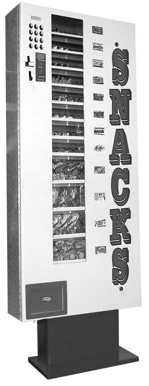
1 Slim Line Snack Vendor 1

2 Operator s Manual INTRODUCTION Congratulations on the purchase of your vending machine. This vending machine has been designed to give you many years of dependable service. It requires little maintenance and is easy to set up and operate. READ THIS MANUAL COMPLETELY Your vending machine is designed to operate simply and reliably, but to take full advantage of your vendor, please read this owner s manual thoroughly. It contains important information regarding installation and operations, as well as a brief trouble-shooting guide. EQUIPMENT INSPECTION After you have received your vendor and have it out of the box, place it on a secure surface for further inspection. Note: Any damages that may have occurred during shipping must be reported to the delivery carrier immediately. Reporting damages and the seeking of restitution is the responsibility of the equipment owner. The factory is willing to assist you in this process in any way possible. Feel free to contact our Customer Care Department with questions you may have on this process. It is important that you keep the original packaging for your vending machine at least through the warranty period. If your machine needs to be returned for repair, you may have to purchase this packaging if it is not retained. Once you have your vendor located, we suggest that you keep this manual for future reference, or you can view this manual online at Should any problems occur, refer to the section entitled TROUBLESHOOTING. It is designed to help you quickly identify a problem and correct it. For Service and Customer Care in the US: 8:30 a.m. - 4:00 p.m. CST. Mon - Fri ext Fax customercare@seaga.com For Service and Customer Care in Europe: 9:00 a.m. - 5:30 p.m. Mon - Fri +44(0) (0) Fax service@seaga.co.uk For Service and Customer Care in Asia: 9:30 a.m. - 6:00 p.m. Mon - Sat +91 (0) (0) Fax service@seagaindia.com Seaga Manufacturing, Inc. 700 Seaga Drive Freeport, IL U.S.A. Seaga UK Ltd. 5 Leodis Court, David Street Leeds, LS11 5JJ UK Seaga India Pvt Ltd. 309A, MIE Bahadurgarh, Haryana seaga.com 2
3 The Slimline Series Snack Vendor This Operator s Manual is divided into Four (4) main sections: Unpacking your Vendor, Brief description of Vendor, Service Mode and Fault Analysis. IMPORTANT NOTICES Your vendor is intended for indoor use only Your vendor must be set on a level, well supported location and wall mounted. Always unload vendor before transporting it. Remove the plastic cable ties from each helix coil. Remove any protective sheets from under the Helix coil support plates before loading the vendor. Do not load your vendor with disfigured or damaged product. Section 1 UNPACKING YOUR VENDOR FIXING OF BASE PLATE Your Vendor comes with the vertical support plate affixed on to the Body. The Base Plate and mounting screws can be found in the packing box. Remember to tighten the base plate on to this vertical support plate at the time of installation. HOW TO LOCK & UNLOCK THE DOOR OF SL3000 SNACK VENDOR Your Vendor has 2 locks, one each at the bottom and top of the front door (Fig. 1). To open the door, insert the Key in the locks and turn counter clockwise. The door can now be opened. To lock the door, turn the keys clockwise in both the locks. The paper sheets under the Helix coil support plates must also be removed before loading the vendor. ELECTRICAL CONNECTION Your snack vendor requires an input of 12 volt DC. Section 2 BRIEF DESCRIPTION OF Vendor Fig 1 Photo of machine with door open Circuit Board 3

4 Coin mech Helix Coils Locks Coil Support Plate Front Door Panel cover for Driver Motors Battery Base plate Vertical support plate GENERAL DESCRIPTION The snack vendor may be driven by a 12-volt battery or via a permanent 12 VDC supply obtained through an AC/DC adapter. The vendor incorporates a Multi Functional Controller Board with a range of features such as 12 individual selections, multiple coin handling, and a compact size. KEYPAD AND LCD DISPLAY The Keypad is touch sensitive. Light pressure will be necessary to activate each number. The vendor s Keypad is used by the customer to make their selection and by the operator to set and test the many functions of the vendor. DELIVERY SYSTEM The delivery system of your snack vendor consists of the Keypad, LCD Display, Driver Motors, Coil Support Plates and Helix Coils. The customer inserts money and enters their selection on the Keypad. The selected Driver Motor turns the Helix Coil that vends the product. LOADING PRODUCT To present your product in an attractive and professional manner as possible, do not load damaged items. Note: The size of the item being vended must be larger than the helix coil but smaller than the coil support plate to vend correctly. Never force an oversized item into the helix coil or attempt to vend an item that is smaller than the helix coil as this will create problems and deter customers. BATTERY MODE OF OPERATION During Battery mode, the machine operates in Sleep Mode. This means that when the machine is not in operation (between vends), it will automatically shut down in order to save battery power, thus prolonging the life of the battery. During Sleep Mode the machine display turns off its left hand digit (unless there is a value greater than 0 present) and the machine monitors to see if a coin has been inserted or a button pressed in order to wake-up. The following conditions will wake-up the machine from Sleep Mode. 1. Coin Insertion 2. Selection Button Press 3. Black (Reset) Button Press 4. Red Service Button Press On Wake-up the machine will only go back to Sleep Mode under the following conditions: 4
5 1. Directly after a vend has been made (Unless there is excess credit present in which case the machine will wait a further 60 seconds before going to sleep). 2. After 30 seconds after a selection has been pressed and the machine contains product. 3. After 20 seconds after a selection has been pressed and the machine does not contain a product. 4. After 5 seconds if an invalidated coin has been inserted and the machine contains product. 5. After 60 seconds after a coin has been inserted and validated. 6. After 5 seconds if the machine is completely empty. 7. After 5 seconds after if the machine is out of order. 8. After 5 seconds after the black (reset) button is pressed and the machine is empty. 9. After 20 seconds after the black (reset) button is pressed and the machine contains product. 10. After 8 seconds after leaving service mode These values are extended each time a selection is pressed or coin inserted to a maximum of 60 seconds. When the machine goes to sleep, the following messages are displayed under set conditions When Awake When Asleep i (Decimal points always on) ii (Decimal points always on) iii. Free Fr.ee (Decimal points always on) iv. Test Te.st (Decimal points always on) v. Out of Ordr F-Er (Fatal Error set) vi (Decimal point always on) When the vending machine detects that a battery is low an error code will be displayed (51). This code will remain on display until the battery has been replaced and the black reset button has been pressed. When the vending machine detects that a battery is dead, the machine will permanently turn itself off. Section 3 Service Mode Overview The operation of the machine can be adjusted by entering service mode by pressing the red button on the VMC circuit board and then accessing the appropriate operation. Price setting, coin value setting, motor operation and vend-credit criteria can be read and adjusted from here. The user can also perform tests for the motor operation through this mode. Operation 1. Enter Service Mode by pressing the Red Button on the VMC Circuit board Displays Er. ** Any faults that have occurred will be displayed as a two-digit code** If there are no errors the Display will automatically go to Audit Mode Au 2. Each Service Code can then be accessed by repeat pressing of the Service Button Pressing Red Button (AUDIT) Displays Au. Pressing Red Button (PRICE SETTING) Displays PS.-- Pressing Red Button (COIN VALUE SETTING) Displays Cn. Pressing Red Button (CONTROL WORD SETTING) Displays Ct.** Where ** is current word Pressing Red Button (ASSIGNMENT) Displays AS. Where ** is current motor vending Pressing Red Button (APPLICATIONS) Displays AP. Pressing Red Button (EXIT Version #) Displays F*. ** to Service Mode can be exited by pressing the Red Service Button, the Reject button or automatically if the LCD Display has remained idle in service mode for up to 60 seconds. 5
6 Notes: - If a selection button/service button is not pressed within 45 seconds then the Display will automatically exit from Service Mode. - If a selection button is pressed, the Display will automatically exit from Service Mode 60 seconds after the last button pressed. - Pressing the reject button also exits the Display from Service Mode Audit Within Service Code AU (Audit) readings can be taken from the Display with regards to cash taken, and number of products vended. The following details can be obtained on the Display. 1. Total Cash Taken (up to ) 2. Total Product Vended (up to 9999) 3. Individual Product Vended (from each selection) up to 999 i. Press the Red Service Button repeatedly till the LCD Displays Au. You are now in Audit Mode ii. Press Selection 1 to reveal the total cash ($/ / ) and (c/p) taken Displays ****and--. ** iii. Press Selection 2 to reveal the total product vended Displays **** iv. Press Selection 3 to reveal the individual product vended The display scrolls through each selection displaying the quantity vended 1.*** to 12.** Returns to Au at end of routine. v. Press Selection 4 to clear all the Total Sales Results Displays clr vi. Press Red Service Button to scroll to exit or press Reject Button to exit. Price Setting Price Setting can be done by entering Service Code PS. Each selection can be allocated any price from to 99.99, and is achieved by inserting coins to vend amount and allocating the amount to each selection. i. Press the Red Service Button repeatedly till the LCD Displays PS. You are now in Price Setting Mode ii. Insert coins to first desired price (for simplicity set the lowest price first) iii. Credit will accumulate on the display Displays **. ** iv. Press desired selection button to store displayed credit to that selection Displays p.set v. Insert additional coins if required. vi. Press Red Service Button to scroll to exit or press Reject Button to exit. Notes: - Prices may be set from to (depending upon coin vales) - It is not possible to set a zero price. - The default price setting is Coin Value Setting Coin Value setting allows for the changing of validator or Acceptors with different output maps. The machine is capable of accepting up to 15 different coin values. Values can be adjusted from to Press the Red Service button repeatedly until Displays Cn. You are now in the Coin Value setting Mode You first need to set the value for the coin 2. Press Selection Button 1 to increment the --.** Value Displays 00.** 3. Press Selection Button 2 to decrement the --.** Value Displays 00.** That is the cent/pence value set, now we need the dollar/euro/pound value 4. Press Selection Button 3 to increment the **. Value Displays **.?? 5. Press Selection Button 4 to decrement the **. Value Displays **.?? Now with the value on the display, insert the coin for which the value must be assigned to. 6. Insert Required Coin until it is accepted to store value to that coin Displays *.set 7. Repeat steps 3 to 7 till coins are set. 8. Press Red Button to exit or press Reject Button to exit. 6 [Where * represents the coin identity a-l]
7 Coin Output Map No IDENT Default Adjustable 1 A X YES 2 B X YES 3 C X YES 4 D X YES 5 E X YES 6 F X YES 7 G X X YES 8 H X X YES 9 I X X YES 10 J X X YES 11 K X X YES 12 L X X X YES 13 M X X X X NO 14 N X X X NO 15 O X NO Notes: - Coin Values between and can be set to any coin - Setting a value of to a coin still allows the coin to be accepted. - The machine will automatically exit from Coin Value Setting within 60 seconds unless a button hasn t been pressed or coin inserted in that time. - All the variable coin values may be set at the same value if required. Control Word Setting This is essentially to do with the coin handling and vend-credit status. The Control Word is a two (2)-digit number used to indicate to the vendor the required method of operation. This controls the operators desired relationship between coins inserted and vend price depending upon the power supply. The code is input within the Service Code count. CONTROL WORD MAP Code Battery Mains Escrow Credit Vs Vend Price (before vend is performed) Excess Credit (difference between credit and vend price) 01 X X X CREDIT= VEND PRICE None 02 X X X 0.99> (CREDIT-VEND PRICE]> 0 Excess Credit Cancels [if any] 03 X X X CREDIT> VEND PRICE Excess Credit Cancels [if any] 04 X X X CREDIT> VEND PRICE Excess Credit Carried Forward 05 X X X CREDIT> VEND PRICE Excess Credit Carried Forward for 60 sec 06 X X X FREE VEND NO CREDIT None REQUIRED 07 X X X TEST VEND- NO CREDIT REQUIRED None Press the red service button repeatedly until Displays Ct.** (where ** is current value) You are now in Control Word Setting To change the current value, we first need to adjust the displayed code Press Selection Button 1 to increment the --.** value Displays Ct.** Press Selection Button 2 to decrement the --.** Value Displays Ct.** That is the control word set; now we need to store it Press Selection Button 4 to store the new Control Word Displays Cntr set Press Red Service Button to exit or Press Reject Button to exit. 7
8 Notes: The default Control Word is 03 (Excess Credit Cancels) Codes 05 [Multi-vend with Time out] allows for the excess credit to be carried forward on the credit for up to 60 seconds. This time is prolonged if a coin is inserted or a selection is pressed for a further 60 seconds from that input. After 60 seconds the excess is cancelled. The time out canceling only applies to excess credit (surplus credit after a vend) and not credit inserted prior to any vend. The setting of a Control Word outside of the allocated codes, results in the machine reverting back to its original code (not default) The machine will return to Normal Code {00.00} 60 seconds after the last button has been pressed unless the Red Service Button has been pressed or the reject is pressed. During Free Vend the machine will display FrEE - All selections will vend without coins - Prices can be set during Free Vend - Appropriate Audit Registers will be incremented (Product sales) - There is no automatic exit from this mode, this must be done through Service Code Ct During Test Vend the Machine will display tes - All selections will vend without coins - Appropriate Audit Registers will not be incremented - Coin input is enabled with coins inserted being displayed for 1 second only - Prices cannot be set during Test Vend - There is no automatic exit from this mode, this must be done through Service Code Ct Motor Assignment Each selection is vended by action of the Driver Motor. There are Twelve [12] Driver Motors clipped to the rear of each Helix coil support tray. To Remove a Driver Motor: 1. Unplug vendor, 2. Remove the screws from the panel cover of the Driver motors, and open the panel 3. Disconnect the wiring harness from the motor 4. Remove Helix Coil from Driver by lifting the front end of the coil up with one hand while guiding the rear of coil with the other hand. 5. Depress the top tab on the Driver Motor, tilt the motor backwards and lift the Driver Motor free Fig. 2 Remove a Driver Motor 6. To Replace Driver Motor repeat the above procedure in reverse order Test Sequence This tests the operation of all the motors in the machine. This is useful to re-align any jammed motors. 1. Press the Red Service Button to Enter Service Mode to scroll to Displays AP. You are now in applications Mode 2. Press Selection 1 to activate test sequence Displays test The machine will now perform a test as outlined below any faults that occurred will be indicated by a 2 digit code at the end of the Test Sequence. Displays Er.** where ** may be a 2 digit code 3. Press Red Service Button to exit or Press Reject Button to exit. 8
9 Notes: - The test sequence may activate a motor for two cycles; this is normal. - If after a test a fault code appears, correct the fault and test again. - The Display will return Normal Mode 60 seconds after the last button has been pressed unless the Red Service has been pressed or the reject is pressed. Test Code Map TEST WHAT IS VISIBLE ACTION 1 2 Escrow Return Power Displays TEST Escrow Return Opens [if present] Power Status Checked 3 4 LEDS Price Setting Displays all Column LEDS on Ensure all LED Segments Illuminate Confirm Prices are set 5 6 Escrow Keep Displays PL.** [Timing Value] Escrow Keep Opens [if present] Confirms Coin Values 7 8 Motor 1 Control word Displays 01.-* where * is motor Version Motor 1 operates [if present] Confirms that a valid control word is set 9 10 Motor 2 Motor Assignment Displays 02.-* where * is motor Version Motor 2 operates [if present] Confirms that a valid motor assignment is set Motor 3 Coin count value Displays 03.-* where * is motor Version Motor 3 operates Confirm that a valid coin count value is set Motor 4 Audit Displays 04.-* where * is motor Version Motor 4 operate [if present] Confirms that all audit registers are valid Motor 5 Timing belt Displays 05.-* where * is motor Version Motor 5 operates [if present] Confirms that valid timing belt value is set 17 Motor 6 Displays 06.-* where * is motor Version Motor 6 operates [if present] Etc Motor End of Test Displays 0-.** Where ** is a fault found during test Section 4 Fault Analysis Within the machine there is an internal fault analysis. Every 0.1 second the machine will do a self analysis test. This test does not affect the normal operation of the machine. There will be no change of status of the machine from a users point of view. The machine will still accept coins, display prices and vend products even during self analysis test. If the machine observes a problem it will double verify the cause and store the error, which will be displayed during service mode. To display an error code, simply enter service mode by pressing the red button. The error code will be displayed intermittently. To clear an error code, simply exit service mode (rectify error if necessary). Note: If more than 5 normal error codes have been detected the machine will assume Fatal error status putting the machine Out of Ord(e)r. Code Description Remedy Fault Code Map -- No error present None 00 Empty Error Location None 01 Motor 1 Error Remove Jam-Activate Test Sequence-Exit Service Mode 02 Motor 2 Error Remove Jam-Activate Test Sequence-Exit Service Mode 03 Motor 3 Error Remove Jam-Activate Test Sequence-Exit Service Mode 04 Motor 4 Error Remove Jam-Activate Test Sequence-Exit Service Mode 05 Motor 5 Error Remove Jam-Activate Test Sequence-Exit Service Mode 06 Motor 6 Error Remove Jam-Activate Test Sequence-Exit Service Mode 07 Motor 7 Error Remove Jam-Activate Test Sequence-Exit Service Mode 08 Motor 8 Error Remove Jam-Activate Test Sequence-Exit Service Mode 09 Motor 9 Error Remove Jam-Activate Test Sequence-Exit Service Mode 10 Motor 10 Error Remove Jam-Activate Test Sequence-Exit Service Mode 11 Motor 11 Error Remove Jam-Activate Test Sequence-Exit Service Mode 12 Motor 12 Error Remove Jam-Activate Test Sequence-Exit Service Mode 9
10 13 Motor 13 Error Remove Jam-Activate Test Sequence-Exit Service Mode 14 Motor 14 Error Remove Jam-Activate Test Sequence-Exit Service Mode 15 Motor 15 Error Remove Jam-Activate Test Sequence-Exit Service Mode 16 Motor 16 Error Remove Jam-Activate Test Sequence-Exit Service Mode 30 Zero Price Setting Reset all prices - Exit Service Mode 31 Zero Coin Count Value Reset Coin Count Value - Exit Service Mode 32 Zero Control Word Reset Control Word Value - Exit Service Mode 33* Zero Coin Value Reset Coin Value - Exit Service Mode 35 Incorrect Motor Version Motor Version outside of norm. Confirm Motor Version 40 Data Corrupt Price Reset all Prices [Fatal error] - Exit Service Mode 41 Data Corrupt Coin Reset Coin Values [Fatal error] - Exit Service Mode 42 Data Corrupt Control Reset Control Code [Fatal error] - Exit Service Mode 43 Data Corrupt Selection Reset Motor selection [Fatal error] - Exit Service Mode 44 Fatal Power Up Confirm Prices, Product codes and Coin values - Exit Service Mode 45 Power Interrupt Possible Fraud attempt - Exit Service Mode 46 Invalid Coin Output Code Replace/Reprogram Coin Acceptor 47* Button Panel fault Check all buttons are operating currently - Exit Service Mode 48 Coin Validator Error/Fault Check operation of Coin acceptor - Exit Service Mode 49* Coin Validator alarm Possible fraud on Coin acceptor Check operation of Coin Acceptor 51 Battery Low Replace Battery - Exit Service Mode Press any selection button 5 times 52 Coin Acceptor Rate Low Check Coin Acceptor- Check battery - Exit Service Mode 53 Battery Dead Replace Battery - Exit Service Mode - Press any selection button 5 times 55* Printer Communication Error Check Printer operation Disconnect printer 56* Change giver Comm s Error Check Change giver operation 57* Modem Communication Error Check Modem Operation 58* Note/Bill reader Comm s Error Check Note/Bill reader operation 59* Cash-Less device Comm s error Check Cash-Less device operation 60* External Alarm Activation Alarm has been activated check for machine tampering 61* Escrow Keep Time-out Check Escrow Unit- Activate Test Sequence Exit Service Mode 62* Escrow Return Time-out Check Escrow unit- Activate Test Sequence Exit Service Mode 70* EEPROM Write Error Check Prices and Coin data 71* EEPROM Read Error Check Prices and Coin data 99* Machine Lock-up Code Required-Consult Machine Supplier Note: * Reserved Codes Not active in current model. FACTORY DEFAULT SETTING The vendor can be reverted back to factory defaults by the user by entering service code 6. Care must be taken while doing this as all data will be lost and will have to be entered again. A list of factory defaults is as follows: DATA DEFAULT VALUE TO CHANGE Standard Audit Totals Prices [all selections] Service Code PS Coin Value Settings As per Coin Output Map Service Code Cn Coin Count Value 15 [if escrow present] Service Code Cn 99 [if no escrow present] Credit [Display] Control Word 3 [excess credit cancels] Service Code Ct Motor Version Version 1 [all motors] Service Code AS Motor Timing Value 7 Service Code AS Motor Assignment Selection 1 Motor 1 etc Service Code AS Motor Backup No-Individual Assignment (1) Service Code AS Not active in current model 1. Press the Red Service Button to enter Application Mode Displays Ap.- You are now in application mode 10
11 2. Press and hold selection 2 for seconds till Displays set The machine will automatically exit from service mode and display Out Of Ord(e)r 3. Press Red Service Button to re-enter Service Mode and re-configure settings. TROUBLESHOOTING Listed below are some of the common faults along with their remedies. Always, if possible, perform a machine test to see if a fault rectifies itself. Motor does not work at all and - Sold Out Displays on button press Product has jammed - Remove any jam and enter and exit Service Mode to remove error code Connecting Cable has dislodged - Ensure all cable are inserted correctly Price setting set to zero - Reset prices for desired selection Selection button assigned to wrong motor - Reset Selection Assignment Machine Has experienced a Fatal Error - Enter Service Mode to view error and remedy accordingly - Display shows Vend Price on selection press - Column empty switch - Display shows Temporarily - No change in Display occurs on selection press The Incorrect Motor Spins on selection press The Machine will not vend but displays --. on the Display on button press The Display is illegible The Machine will not power up and the display is blank Inserted credit is outside of the boundary of the control word setting - Inserted Credit below the vend price - Confirm and reset Control Word Power not being supplied to motor - Check that all cables are inserted correctly - Replace Motor/or connecting cable Problem with Selection Panel Button - Ensure that all cables are inserted correctly - Replace Selection Panel Motor back up in operation - Reset Motor back up Power not been applied to motor-error with dispensing motor - Replace motor - Replace cabling Machine entered a loop state - Reset control board by pressing Black Reset Button Machine entered a loop state - Reset Control Board by pressing Black Reset Button Power lost to machine - Confirm that power is going to machine HOW? - Check to see if AC/DC adapter is warm. If its cold then this would indicate that power is not going to the machine - Check that Fuse on Circuit Board is not Blown - Check that all connectors are fully in place Battery is completely dead - Replace Battery and depress the Black Reset Button Power is not applied to circuitry - Replace Control Board 11
12 Pressing a selection button gets no reaction of the display [either the price or sold out] An inserted coin is continually rejected An inserted coin is accepted but gives no credit or incorrect credit The Display counts up credit or does not cancel a credit During price setting machine does not hold credit but returns to Credit cancels and/or escrow opens after a certain number of coins have been inserted An incorrect set-up was performed and now the user is confused and frustrated I have tried all of the above. I still cannot get the machine to work as desired. Loose connection - Check that all connectors from the panel are plugged in correctly at both the panel end and the circuit board Button panel is faulty - Replace panel The machine entered a Loop state - Reset Control Board by pressing Black reset Button A fatal error has occurred - Enter Service Mode to view error and remedy accordingly Coin Mechanism is blocked or dirty - Remove Power and clean Acceptor - Replace Acceptor if necessary Coin Mechanism connection lead is disconnected The coin inserted is not valid coin accepted by acceptor The coin acceptor Inhibit function is incorrectly set An incorrect coin value setting has been entered - Reset Coin Value setting HOW? - Press Red Service Button till Cn Reset coin values The Machine entered a Loop state - Reset Control Board by pressing Black Reset Button Credit may have remained after a vend - Press Black [Reset] Button to Clear Credit - Confirm that proper Control Word has been set Coin Validator Connector inserted in-correctly - Check Connector Machine set to test mode - Change control word An incorrect coin count value has been set - Reset coin count value to a higher setting Machine assumes an escrow is present and over-loaded with coins - Confirm that correct Control Word is set for the machine - Activate the default settings on the machine Press the red Service Button till AP Hold down Button 2 till [set] appears - Press the Black Reset Button [out of ordr] - Activate the Test Sequence - Test Operation in test vend mode Notes: 12
SlimLine SL3100 Snack Vendor (Íntelli Version) OPERATOR S MANUAL
 OPERATOR S MANUAL") SlimLine SL3100 Snack Vendor (Íntelli Version) OPERATOR S MANUAL Version: 2010-GJP-1 1 INTRODUCTION Congratulations on the purchase of your new Slimline Snack Vendor. This snack vendor has been designed
SlimLine SL3100 Snack Vendor (Íntelli Version) OPERATOR S MANUAL Version: 2010-GJP-1 1 INTRODUCTION Congratulations on the purchase of your new Slimline Snack Vendor. This snack vendor has been designed
POCKET GUIDE ROUTINE MAINTENANCE, SAFETY, INSTALLATION & TROUBLESHOOTING
 The 350 REFERENCE SERIES MULTI-PRICE TOTALISER POCKET GUIDE ROUTINE MAINTENANCE, SAFETY, INSTALLATION & TROUBLESHOOTING CashFlow CashFlow CashFlow C ashflow CashFlow CashFlow Cas hflow CashFlow CashFlow
SERVICE and PARTS MANUAL
 SERVICE and PARTS MANUAL Rev.1 10.2017.EL950.1.3.1074C 1 INTRODUCTION Congratulations on the purchase of your vending machine. This vending machine has been designed to give you many years of dependable
UTB-400c INSTALLATION AND OPERATION GUIDE COINCO UTB 400-C TEST BOX
 UTB-400c INSTALLATION AND OPERATION GUIDE COINCO UTB 400-C TEST BOX The UTB 400-C is a fully functional Vending machine simulator with configurable settings. It supports MDB, Executive and BDV protocol
1.0 EF MODULE BASIC INSTRUCTIONS...
 Contents 1.0 EF MODULE BASIC INSTRUCTIONS... 1 NAVIGATING THE AVAILABLE MENUS...1 MAIN MENU DESCRIPTIONS & MENU NAVIGATION...2 REPORTING AND PRINTING FEATURES...3 NAVIGATING THE MAIN MENU LIST...4 ACCEPT
Thomas. Change Machine. Operator Guide
 Thomas 5002 Change Machine Operator Guide Contents On Receiving Your New Change Machine...3 Coin Mech Installation...3 Fitting...3 Removing...3 Opening...3 Switching On...4 Machine Alarm and Alarm Keyswitch
Keypad Lock. Operation and Service Manual. Order parts online
 Keypad Lock Order parts online www.follettice.com Operation and Service Manual 801 Church Lane Easton, PA 18040, USA Toll free (800) 523-9361 (610) 252-7301 Fax (610) 250-0696 www.follettice.com 00163345R00
Holland Computers, Inc. Crane Kit Manual Part Number RA-CRANE-KIT
 Holland Computers, Inc. Crane Kit Manual Part Number RA-CRANE-KIT SECTION 1 - Introduction Description This kit has been manufactured as a replacement gantry and electronics for existing machines using
QW-5953 Credit Card Ready Wash Entry System
 QW-5953 Credit Card Ready Wash Entry System Instruction Manual Phone +64 3 338-3139, Fax +64 3 338-3725, Anztec Ltd, PO Box 3288, Christchurch, New Zealand www.anztec.com email sales@anztec.com Page 1
SERVICE and PARTS MANUAL
 Ambient and Refrigerated Models SERVICE and PARTS MANUAL Revision 2.EL950 1.3.1074C 18.2 1 INTRODUCTION Congratulations on the purchase of your vending machine. This vending machine has been designed to
Trouble Shooting. Symptoms: Gate Access Control Computer connected to the Facility Computer
 Trouble Shooting Symptoms: Gate Access Control Computer connected to the Facility Computer "Unable to read from controller (CTS lost)" error message on computer screen Do Power checks Do controller (computer
GS Cash Card Loader
 GS 1085 Cash Card Loader May 2007 Table of Contents SALES AND SERVICE... 3 QUICK REFERENCE SET-UP GUIDE. 4 FUNCTIONAL OVERVIEW... 6 INSTALLATION - SETUP... 8 IDENTIFYING THE COMPONENTS... 9 SETUP THROUGH
Coin Manager CN MDB Installation Guide-Canada. Set Up Screen Features (Continued) GENERAL INFORMATION
 GENERAL INFORMATION") Set Up Screen Features (Continued) Fig.18 Coin Manager 7512 CN MDB Installation Guide-Canada GENERAL INFORMATION To View errors - Press the yellow mode button (highlighted View ) to gain access. Use the
Set Up Screen Features (Continued) Fig.18 Coin Manager 7512 CN MDB Installation Guide-Canada GENERAL INFORMATION To View errors - Press the yellow mode button (highlighted View ) to gain access. Use the
Validator Update Instructions for Rowe BC1200 $1 - $20
 Validator Update Instructions for Rowe BC1200 $1 - $20 Kit Overview The purpose of the kit is to replace the Rowe BA50 transport and stacker with a 120 volt Mars validator with a compact mask. The kit
Minivend 4 Instruction Booklet
 Minivend 4 Instruction Booklet CONTENTS PAGE INTRODUCTION 1 OTHER KEY FEATURES 1 CAUTIONS 2 OPERATOR MENU 3 SETTING UP COSTS AND CASH LIMIT 3 CUSTOMISING THE DISPLAY 4 REPORTING USING THE DISPLAY 5 REPORTING
Holland Computers, Inc. Crane Kit Manual Part Number RA CRANE KIT
 Holland Computers, Inc. Crane Kit Manual Part Number RA CRANE KIT I. SECTION 1 Introduction a. Description This kit is designed for professional installation only. It has been manufactured as a replacement
Money Order Terminal User Guide for VeriFone Vx570
 Money Order Terminal User Guide for VeriFone Vx570 5/2013 Equipment Contents...3 Chapter 1 - VeriFone Terminal Front Panel Features...4 Figure 1 VeriFone Terminal Front Panel Features... 4 Chapter 2 -
TOUCHLOCK compact. Master code: Paxton Access Ltd. ins TOUCHLOCK compact kit. Document Contents. Instructions for the following:
 ins-016 160499 TOUCHLOCK compact 100-050 TOUCHLOCK compact kit Instructions for the following: 526-886 TOUCHLOCK compact keypad 100-050 TOUCHLOCK compact kit Master code: Document Contents About this product...2
TR Box Vending Machine Manual
 TR-3631 Box Vending Machine Manual Preface TR-3631 Box Vending Machine Welcome to use our box vending machine! Before you install and operate this machine, please read the manual carefully. In order to
INSTALLATION INSTRUCTIONS FOR YOUR MULTI-6
 INSTALLATION INSTRUCTIONS FOR YOUR MULTI-6 Your Multi-6 vending machine has been set up at the factory and should give many years or trouble free operation. Health & Safety. The Multi-6 vending machine
MDB Coin Changer and MDB Bill Acceptor to RS 232 Interface
 Shanghai Wafer Microelectronics Co., Ltd. 23E,Liang Feng Building,NO.8,DongFang Road,Shanghai,China Tel.: (0086)21 5187 0528 Fax: (0086)21 5045 4820 MDB Coin Changer and MDB Bill Acceptor to RS 232 Interface
Diamond Cabinet Slant Top Users Manual Revision 1.0
 Diamond Cabinet Slant Top Users Manual Revision 1.0 1 Table of Contents 1.1 Sections 1 Table of Contents...2 1.1 Sections...2 1.2 List of Figures...3 1.3 List of Tables...3 2 Revision History...5 3 Overview...6
eforce 150 Keyless Entry Owner s manual & User s guide For Model 3090
 eforce 150 Keyless Entry Owner s manual & User s guide For Model 3090 This manual contains important operation, maintenance & warranty information. Save this manual for future reference TABLE OF CONTENTS
6.0 SERVICE PROGRAMMING
 6.0 SERVICE PROGRAMMING SERVICE MODE Access the service mode by pressing the mode switch on the control board (refer to Figure 3.1). After displaying any errors, the first function is displayed. Press
212iL Rev. 1.1
 212iL 1 International Electronics, Inc. 427 Turnpike Street Canton, Massachusetts 02021 212iL (illuminated Luxury) Keypad Single Unit Keypad- Control Installation Manual Features: 120 User Capability Illuminated
Wi-Card Skeet-Trap Claymate Operator and User Manual
 Claymate... Technology that Counts Wi-Card Skeet-Trap Claymate Operator and User Manual Page 1 Thank you for purchasing a Promatic Wi-Card Skeet-Trap Claymate. The Promatic Wi-Card Sporting Claymate is
Digital Keypad Introduction
 K2 Digital Keypad Introduction The K02 uses the latest microprocessor technology to operate door strikes and security systems that require a momentary (timed) or latching dry contact closure. All programming
Operating Instructions
 Model 6121 Motorized Electronic Combination Lock Operating Instructions The Sargent & Greenleaf Model 6121 combines ease of operation with security. Its advanced electronic circuit design makes it easy
Control-panel messages
 Control-panel messages Control panel message Description Recommended action 10.32.YY UNAUTHORIZED SUPPLY Unauthorized supply in use A new, non-hp supply has been installed. This message appears until you
TDM To MiniMech conversion ProceDure
 TDM To MiniMech conversion ProceDure (Model 9100 ATM) TDN 07102-00079 Apr 1 2009 CorporATe HeAdquArTers: 522 E. Railroad Street Long Beach, MS 39560 PHONE: (228) 868-1317 FAX: (228) 868-0437 COPYRIGHT
Ratio Feeder Series J+ Advanced Pumper Controller
 UNPACKING Figure 1 J Plus Controller Please open and inspect your package upon receipt. Your package was packed with great care and all the necessary packing materials to arrive to you undamaged. If you
ENFORCER SK-1131-SQ. Digital Access Keypad with 5A Relay Output MANUAL. Digital Access Keypad Manual. Also available from SECO-LARM: Outdoor Keypads
 User Operation for the SK--SQ Note: n n n nindicates. Using the User Codes: A. User codes operate the door (4-8 digits long). the inhibit code. Note: u u u uindicates Press u u u u the user code. B. The
NOTE: Optional Counter Interface Unit for Multi pricing must already be installed. for Ricoh its part # EDP code
 INSTRUCTIONS FOR INSTALLING VENDAPIN LLC VENDING PRODUCTS TO RICOH, SAVIN, GESTETNER AND LANIER COPIERS Note for 2-price capability, the Coin Box or Card Reader must be set to Steering Mode. For a full
Troubleshooting CHAPTER
 CHAPTER 1 1 1 1 0 1 1 0 1 1 0 1 1 0 1 1 0 1 1 0 1 1 0 1 1 1 0 1 6 0 1 1 0 1 1 0 1 0 1 10 1 0 1 1 0 1 0 1 1 0 1 0 1 1 0 1 10 Troubleshooting NOTICE: Information in this manual may change without notice.
PRO ESC - LCD PROGRAM CARD USER MANUAL. The Fantom FR-10 PRO LCD Program Card only applies to the FR-10 PRO 1:10 scale, 2S, 160A brushless ESC.
 PRO ESC - LCD PROGRAM CARD USER MANUAL The Fantom FR-10 PRO LCD Program Card only applies to the FR-10 PRO 1:10 scale, 2S, 160A brushless ESC. The LCD Program Card can be used in two ways as follows: 1.
RS3000 SERIES BILL ACCEPTORS
 Flash Diagnostic Codes RS3000 SERIES BILL ACCEPTORS INSTALLATION GUIDE s of the bill acceptor. Below is a chart that lists all the flash codes of the RS3000 Bill Acceptor and a description of each code.
SMART Coin System QUICK START AND CONFIGURATION GUIDE
 SMART Coin System QUICK START AND CONFIGURATION GUIDE SMART Coin System Quick Start and Configuration Guide 2 SMART Coin System Quick Start and Configuration Guide 1 INTRODUCTION 4 2 ASSEMBLY 5 2.1 Detaching
Revision History E F G H J K Revision Description: K > Allegion Rebranding.
 Notes: Enter any notes here. These notes must include: how many sides of the paper are printed ink color (usually black, may also be one or two specific colors, such as a Pantone value, or 17.000 8.500
Money Order Training Guide for VeriFone Vx570
 Money Order Training Guide for VeriFone Vx570 1/2012 Package Contents and Unpacking... 2 Chapter 1- Terminal Front Panel Features... 3 Chapter 2- Connecting the Document Printer and Terminal... 4 Chapter
AE2600 Australian Series Installation Guide
 AE2600 Australian Series Installation Guide This Bill Acceptor is designed to fit into the standard bill acceptor opening provided by Amusement, Lottery, Kiosk and Vending machine manufacturers. It mounts
SK-1011-SQ Digital Access Keypad with 5A Relay Output
 User Operation for the SK--SQ. Using the User Codes: A. User codes operate the door (4-8 digits long). Press u u u u B. The key must also be pressed if the keypad is in manual-entry mode. Press u u u u
Royal RVV-500 (B) Retrofit Kit
 Retrofit Kit") Optipay BV/RC/CC into a Non-Fascia Vending Machine This document contains information for installing and configuring the JCM Optipay DBV-01 Bill Validator, RC-10 Bill Recycler and A-66 Coin Changer into
Optipay BV/RC/CC into a Non-Fascia Vending Machine This document contains information for installing and configuring the JCM Optipay DBV-01 Bill Validator, RC-10 Bill Recycler and A-66 Coin Changer into
A m e r i c a n C h a n g e r
 A m e r i c a n C h a n g e r 1400 NW 65 TH Place Ft. Lauderdale, FL 33309 AC7700/7800 BILL TO BILL SERIES CHANGER OPERATIONS MANUAL Parts & Service: (954)917-5963 Service Fax: (954)917-5204 Sales: (800)741-9840
IQ PROX. Programming Guide. Series. For use with IQ KP* only
 IQ PROX Series Programming Guide For use with IQ KP* only Congratulations, you have just purchased the IQ KP*series lockset by Marks USA, the most advanced stand-alone door lock and access control system
TROUBLESHOOTING CHAPTER
 CHAPTER TROUBLESHOOTING CAUTION: Turn AC power off before attempting any of the following procedures, unless otherwise specified. Failure to do so may damage equipment, cause personal injury, or void warranty.
Badger Meter Europa GmbH. INSTRUCTION MANUAL Deluxe LCD display for the MN series. September Version MN-Deluxe LCD display-09/01-e
 Badger Meter Europa GmbH INSTRUCTION MANUAL Deluxe LCD display for the MN series September 2001 Version MN-Deluxe LCD display-09/01-e Content Content Page 1. To the owner 1 2. Important information 1 3.
Heightronic 235D Assembly & Operation
 Firmware version A1.002 Heightronic 235D Assembly & Operation Table of Contents TABLE OF CONTENTS... 2 SECTION GENERAL INFORMATION... 3 INTRODUCTION... 3 SPECIFICATIONS... 3 SECTION 2 ASSEMBLY & INSTALLATION...
Index. Disable or Enable Code 06. Definition 02 Factory Default Settings 03 Important Notes 03 Change Master Code 03 Add Code 04
 Index Definition 02 Factory Default Settings 03 Important Notes 03 Change Master Code 03 Add Code 04 Add a User Code Add Multiple User Codes Add an Office Code Add Multiple office Codes Add a Lockdown
Model DNCB 640/448 3DVIS Beginning Production Run 5106CJ
 Coca-Cola Model DNCB 640/448 3DVIS Beginning Production Run 5106CJ Manufactured by Crane Merchandising Systems P.O. Drawer 719 Williston, SC 29853-0719 803-266-5001 fax: 803-266-5049 Visit us on the web:
OPERATION & SERVICE MANUAL VC1100 Series MDB-120 Controller Software 120 Volts, 60 HZ 230 Volts, 50 HZ
 OPERATION & SERVICE MANUAL VC1100 Series MDB-120 Controller 67196-1 Software 120 Volts, 60 HZ 230 Volts, 50 HZ Seaga Manufacturing, Inc. 700 Seaga Drive, Freeport IL USA Phone: 815-297-9500 - Fax: 815-297-1700
TD2100 Electric Gummed Tape Dispenser Owner s Manual
 TD2100 Electric Gummed Tape Dispenser Owner s Manual Marsh Shipping Supply Co. LLC 926 McDonough Lake Road Collinsville, IL 62234 www.msscllc.com Customer Service Phone: (618)-343-1006 Fax: (618)-343-1016
INSTRUCTION MANUAL FOR VEND-MASTER & VEND-MASTER VALIDATOR
 INSTRUCTION MANUAL FOR VEND-MASTER & VEND-MASTER VALIDATOR Dilling-Harris, Inc. 10215 Miller Rd., Dallas, Texas 75238 Tel: (214)348-2662 Fax: (214)348-2914 Table of Contents Subject Page IMPORTANT WALL
Troubleshooting with the control panel
 Troubleshooting with the control panel The tables in this section explain common messages that might appear on the control-panel display. Within each table, the messages and their meanings are listed in
Genmega ATM Error Codes
 Genmega ATM Error Codes Code Description Remedy 20001 Unable to load a cassette. Remove and replace cassette - Check the micro-switch located on the inside left wall of the 20002 Low Cash. "Low Cash Warning"
Vapor Monitor Interface Module
 Manual No: 577013-951 Revision: A Vapor Monitor Interface Module Installation Guide Notice Veeder-Root makes no warranty of any kind with regard to this publication, including, but not limited to, the
VN2600 Canadian Series Installation Guide
 VN2600 Canadian Series Installation Guide This Bill Acceptor is designed to fit into the standard bill acceptor opening provided by Amusement, Lottery, Kiosk and Vending machine manufacturers. It mounts
I. PANEL DESCRIPTION... 1
 Table of Contents I. PANEL DESCRIPTION... 1 II. OPERATING INSTRUCTION... 7 1. MA OUTPUT... 7 1A. GENERAL OPERATION 4-20MA... 7 1B. SELECT 0-20MA OR 0-24MA... 8 1C. ENTER A VALUE LESS THAN 1... 9 2. % (PERCENTAGE)
Treadmill Embedded Touch Screen Won t Power Up
 Treadmill Embedded Touch Screen Won t Power Up E-TRe and E-TRxe This document contains the necessary information to troubleshoot a treadmill with an embedded touch screen that will not power up. Follow
INSTALLATION PROCEDURE FOR THE INNOVEC IPT POWERED PRINTING TOTALISOR
 INSTALLATION PROCEDURE FOR THE INNOVEC IPT POWERED PRINTING TOTALISOR Suite 5, 56-6 Chandos Street, St. Leonards NSW 065/PO Box 35 Spit Junction NSW 088 Australia Phone +6 9906 758 www.innovec.com page
ABM International, Inc. Lightning Stitch Checklist 9/13/2013
 ABM International, Inc. Lightning Stitch Checklist 9/13/2013 1) Piggy backed board assembly (1) Piggy back board assembly tested? Yes No 24v passed XB passed XA passed YB passed YA passed SAFE passed S/S
Understanding printer messages
 Understanding printer s Printer s that appear on the control-panel display relay the normal status of the printer (such as Processing...) or an error condition (such as CLOSE TOP COVER) that needs attention.
SMART POOL BOARD APPLICATIONS GUIDE
 ART POOL BOARD APPLICATION GUIDE IUE A 18 February 2006 File : ART POOL Applications Guide.doc s: Issue Date s A 18/2/06 Original Issue 2005 JCA ystems Ltd Page 1 ART POOL The ART POOL board (P) is a new
EX2000 Series Vending System. User s Manual. Choose ACDI for all your document vending needs User s Manual
 EX2000 Series Vending System User s Manual Choose ACDI for all your document vending needs User s Manual INTRODUCTION... 1 OVERVIEW... 1 Staff Copies... 1 SETUP... 2 UNPACKING THE VENDING SYSTEM... 2
Nova Light Source Range
 Light Source User Guide Nova Light Source Range Models covered by this manual: UFO NOVA DMX UFO NOVA DMX-R UFO NOVA DMX-T UFO NOVA DMX-TR Please read this manual fully before installing, operating or performing
EX2000 Series Vending System. User s Manual. Choose ACDI for all your document vending needs User s Manual
 EX2000 Series Vending System User s Manual Choose ACDI for all your document vending needs User s Manual INTRODUCTION... 1 OVERVIEW... 1 Staff Copies... 1 SETUP... 2 UNPACKING THE VENDING SYSTEM... 2
Lightning Stitch Assembly
 ABM International, Inc. 1 1.0: Parts List Lightning stitch motor and drive assembly (Qty. 1) Lightning stitch piggy backed controller board assembly (Qty. 1) Touchscreen (Qty. 1) 2 9-pin Serial cable (Qty.
ipod Interface for BMW
 ipod Interface for BMW ISBM71 Instruction Manual PROFESSIONAL INSTALLATION STRONGLY ADVISED IMPORTANT NOTE ipod Firmware MUST be updated BEFORE any other step is taken. Otherwise, the ipod will not operate
Jofemar S.A. (31350 Peralta (Navarra, Spain)) Tel Fax
) Tel Fax") Jofemar Jofemar S.A. (31350 Peralta (Navarra, Spain)) Tel. 34-948-751-212 Fax 34-948-750-143 Code: MNP38V03GBV00 Date: June 2001 Page 1 of 29 Table of Contents 1. DESCRIPTION OF THE MACHINE.... 3 1.1 -
Jofemar Jofemar S.A. (31350 Peralta (Navarra, Spain)) Tel. 34-948-751-212 Fax 34-948-750-143 Code: MNP38V03GBV00 Date: June 2001 Page 1 of 29 Table of Contents 1. DESCRIPTION OF THE MACHINE.... 3 1.1 -
Living. Keyfree Connected Smart Lock Manual. smart. The smarter way to protect your home
 smart Living Keyfree Connected Smart Lock Manual Please read the intructions before fitting and using the Keyfree Connected lock. The functions and design of this product can be changed without prior notice
Installation and Operation Back-UPS BR1000G-IN / BR1500G-IN
 Installation and Operation Back-UPS BR1000G-IN / BR1500G-IN Important Safety Information Read the instructions carefully to become familiar with the equipment before trying to install, operate, service
CUBE Micro Station User Guide
 CUBE Micro Station User Guide Models TVS10AC CUBE Micro Station - User Guide 1 of 23 How To Use This Guide This User Guide is a resource to provide you guidelines and best practices as you begin using
INSTALLATION & USER MANUAL
 INSTALLATION & USER MANUAL MODELS EVMS & GSVMS with Rain Sensor 00--0 Fax: 0-- csm@wascoproducts.com www.wascoskylights.com Eastern Facility: Spencer Drive, Unit A, Wells, ME 000 Western Facility: Echo
INSTRUCTION MANUAL. Instruction Manual. Analog Multi-Tube Vortexer Digital Multi-Tube Vortexer
 INSTRUCTION MANUAL Instruction Manual Analog Multi-Tube Vortexer Digital Multi-Tube Vortexer Table of Contents Package Contents............ 1 Warranty............ 1 Installation............ 2 Maintenance
F7_F707_F708 Installation Instruction V1.0 F7_F707_F708. Access Control Terminal. Installation Instructions
 F7_F707_F708 Access Control Terminal Installation Instructions Revised May 2008 About this Guide This guide provides installation instructions only. For information regarding actual operation and configuration
Dexter Washer Programing. Part # 8533-***-*** 03/14
 Dexter Washer Programing 3 PROGRAMMING INSTRUCTIONS: The washer control can be programmed to prompt the user for alternate vend prices, change washer cycle times, temperatures and many other options. This
Secured Series: Hub Plus Kit Single Door Controller Package Installation Manual
 Secured Series: Hub Plus Kit Single Door Controller Package Installation Manual This package is designed to simplify the connections to our Secured Series Hub Plus Controller. This will translate into
Manual. The Secure, Keyless Smart Door Lock. The smarter way to protect your home
 Conexis L Manual The Secure, Keyless Smart Door Lock The smarter way to protect your home Discover Our Range of Products Yale Connected Secure, monitor and control your home with a range of smart security
CopyMate Express User s Guide
 i Copyright 2006 Access Control Devices, Inc. All rights reserved. Table of Contents CopyMate Express 1. CopyMate Express Facts... 3 Key Features:...3 Options:...4 Specifications:...4 2. Preparations...
A TCP/IP network CAT 5 cable If the network is faster than 10baseT a switching hub will be needed Static IP address
 Requirements A TCP/IP network CAT 5 cable If the network is faster than 10baseT a switching hub will be needed Static IP address Power Up A Reader with an Ethernet adaptor installed and the network cable
DOOR INTERCOM SYSTEM WITH 2.4 COLOUR LCD
 DOOR INTERCOM SYSTEM WITH 2.4 COLOUR LCD Model Number: HE414114 INSTRUCTION MANUAL After Sales Support 02 Door Intercom System with 2.4 Colour LCD Warranty Details The product is guaranteed to be free
PROGRAMMING GUIDE. MARKS USA 365 Bayview Ave., Amityville, NY Fax
 PROGRAMMING GUIDE MARKS USA 365 Bayview Ave., Amityville, NY 11701 631-225-5400 1-800-526-0233 Fax 631-225-6136 www.marksusa.com Congratulations, you have just purchased the i-qwik LITE Series lockset
Quick Start. i16 w16 i8 w8 i6 i4 w4 i2 w2. 25W max. 42W max. Input 24V AC/DC 12/24V AC/DC 12/24V AC/DC 12/24V AC/DC
 Quick Start Safety Information: White Light and IR Variants (850nm & 940nm) Caution Risk Group 2. Avoid Exposure / use protection. See Safety Information in FULL Instruction Guide for details. Box Contents:
Battery Operated Acre Counter User Manual SOFTWARE VERSION 6.0. Loup Electronics
 Battery Operated Acre Counter User Manual SOFTWARE VERSION 6.0 Page 1 5/8/14 The battery operated acre counter operates in one of two modes. In sleep mode, the display is blank, and the counter is accumulating
General Information. Section 1. General Information INTRODUCTION FEATURES
 Section 1 General Information General Information INTRODUCTION Programming is done Menu Style with the menus consisting of Main Items and Sub-Items Figure 11 is a good example of how the menu system works
Installation Guide Solid State Meter
 Installation Guide Solid State Meter Document version v0.2 February 2018 1 Where Intelligence Meets Infrastructure TM Contents About this Installation Guide... 3 Transport and storage... 3 Installation
Installation and Operation Manual Back-UPS BR900G-RS
 Installation and Operation Manual Back-UPS BR900G-RS Inventory Safety bu001a This unit is intended for indoor use only. Do not operate this unit in direct sunlight, in contact with fluids, or where there
QC-7600A. Instruction Manual. Anztec, P.O. Box 3288, Christchurch, New Zealand Phone ,
 QC-7600A Instruction Manual Anztec, P.O. Box 3288, Christchurch, New Zealand Phone +64 3 338 3139, www.anztec.com email:sales@anztec.com Serial # Key # Software Ver. QC-7600A Rev 1.2 Page 2 Contents Warning...6
Table of Contents. Unpacking and Inspection Setup Loading the Media Mount the Printer on the Wall... 16
 WPL25/WHC25 Table of Contents Unpacking and Inspection... 1 Setup... 5 Loading the Media... 6 Mount the Printer on the Wall... 16 LED and Button Functions... 17 Troubleshooting... 18 Unpacking and Inspection
ONYX FINGERPRINT PASSWORD LOCK MANUAL
 ONYX FINGERPRINT PASSWORD LOCK MANUAL PREFACE 1. Electronic locks are sensitive and advanced products with fragile micro-chips and hardware. Please be aware that the position and type of environment the
Residential/Light Commercial Remote Control System
 MODULAR CONTROLLER REMOTE CONTROL Residential/Light Commercial Remote Control System OWNER S MANUAL AND INSTALLATION INSTRUCTIONS CONTENTS INTRODUCTION 2 SYSTEM COMPONENTS - REMOTE 3 SYSTEM COMPONENTS
OLOGY HEIGHT-ADJUSTABLE DESKS AND BENCHES. Troubleshooting Guide
 Troubleshooting Guide Power Cable Cantilevers Control Box Active Touch Controller Lifting Column Foot Understructure OLOGY HEIGHT-ADJUSTABLE DESKS AND BENCHES HOW THEY WORK Each Lifting Column contains
ESDI Model A MDB MultiPrice Water Vend Controller Operation and Installation Manual
 ESDI Model 110100-A MDB MultiPrice Water Vend Controller Operation and Installation Manual (Also see Programming & Service Manual) WARNING! ELECTRICAL SHOCK HAZARD! AUTHORIZED PERSONNEL ONLY. EXPOSED 120
Lumina Technical Manual TSP013.doc Issue 4.8 July 2006
 This document is the copyright of Money Controls Ltd and may not be reproduced in part or in total by any means, electronic or otherwise, without the written permission of Money Controls Ltd. Money Controls
PIX-55. Atomic Time Clock. Operation Manual
 PIX-55 Atomic Time Clock Operation Manual Proprietary Notice This document contains proprietary information and such information may not be reproduced in whole or part without the written permission from
2-Way Wireless I/O Expander Installation Guide
 2-Way Wireless I/O Expander Installation Guide For more detailed information please refer to the iconnect Installer Manual provided on our website: www.electronics-line.com Table of Contents 1. Introduction...
GV3000/SE Operator Interface Module (OIM) User Guide Version 2.0 M/N 2RK3000
 User Guide Version 2.0 M/N 2RK3000") GV3000/SE Operator Interface Module (OIM) User Guide Version 2.0 M/N 2RK3000 Instruction Manual D2-3342-2 The information in this manual is subject to change without notice. Throughout this manual, the
GV3000/SE Operator Interface Module (OIM) User Guide Version 2.0 M/N 2RK3000 Instruction Manual D2-3342-2 The information in this manual is subject to change without notice. Throughout this manual, the
Compact Keypad. ins /02/2010. Exit button (push to make) 12V DC release current rating must be less than 1A.
 12V DC release current rating must be less than 1A.") Compact Keypad Grey Exit button (push to make) 1V DC White Black 115V DC (fuse rating 1A) 1V DC release current rating must be less than 1A. The diode current rating must be equal to or greater than the
Compact Keypad Grey Exit button (push to make) 1V DC White Black 115V DC (fuse rating 1A) 1V DC release current rating must be less than 1A. The diode current rating must be equal to or greater than the
CF3000 Dealer Diagnostic Tool Instruction Manual
 CF3000 Dealer Diagnostic Tool Instruction Manual Table of Contents: About the CF3000......3 Important Precautions......4 Components....5 Charging the CF3000......7 Licensing the CF3000.......8 Updating
MSR BASIC & MSR NANO USER MANUAL
 MSR BASIC & MSR NANO USER MANUAL An Introduction The MSR BASIC and MSR NANO are both portable magnetic stripe card readers. They utilize 3.7V Lithium Ion batteries and can run for more than 30 days with
Light Source User Guide
 Light Source User Guide Vega Slimline Plastic Light Source Range Models covered by this manual: UFO VEGA SLP-2700M UFO VEGA SLP-3000M UFO VEGA SLP-4000M UFO VEGA SLP-2700DMX UFO VEGA SLP-3000DMX UFO VEGA