L18 - PowerFlex Drives Configuration & Programming. For Classroom Use Only!
|
|
|
- Ferdinand Blankenship
- 6 years ago
- Views:
Transcription


1 L18 - PowerFlex Drives Configuration & Programming For Classroom Use Only!


2 Important User Information This documentation, whether, illustrative, printed, online or electronic (hereinafter Documentation ) is intended for use only as a learning aid when using Rockwell Automation approved demonstration hardware, software and firmware. The Documentation should only be used as a learning tool by qualified professionals. The variety of uses for the hardware, software and firmware (hereinafter Products ) described in this Documentation, mandates that those responsible for the application and use of those Products must satisfy themselves that all necessary steps have been taken to ensure that each application and actual use meets all performance and safety requirements, including any applicable laws, regulations, codes and standards in addition to any applicable technical documents. In no event will Rockwell Automation, Inc., or any of its affiliate or subsidiary companies (hereinafter Rockwell Automation ) be responsible or liable for any indirect or consequential damages resulting from the use or application of the Products described in this Documentation. Rockwell Automation does not assume responsibility or liability for damages of any kind based on the alleged use of, or reliance on, this Documentation. No patent liability is assumed by Rockwell Automation with respect to use of information, circuits, equipment, or software described in the Documentation. Except as specifically agreed in writing as part of a maintenance or support contract, equipment users are responsible for: properly using, calibrating, operating, monitoring and maintaining all Products consistent with all Rockwell Automation or third-party provided instructions, warnings, recommendations and documentation; ensuring that only properly trained personnel use, operate and maintain the Products at all times; staying informed of all Product updates and alerts and implementing all updates and fixes; and All other factors affecting the Products that are outside of the direct control of Rockwell Automation. Reproduction of the contents of the Documentation, in whole or in part, without written permission of Rockwell Automation is prohibited. Throughout this manual we use the following notes to make you aware of safety considerations: Identifies information about practices or circumstances that can cause an explosion in a hazardous environment, which may lead to personal injury or death, property damage, or economic loss. Identifies information that is critical for successful application and understanding of the product. Identifies information about practices or circumstances that can lead to personal injury or death, property damage, or economic loss. Attentions help you: identify a hazard avoid a hazard recognize the consequence Labels may be located on or inside the drive to alert people that dangerous voltage may be present. Labels may be located on or inside the drive to alert people that surfaces may be dangerous temperatures.
3 PowerFlex Drives Configuration & Programming Contents Before You Begin... 5 Network Setup... 5 Drive Configuration (REQUIRED!!!!!)... 6 About the Hardware... 7 PowerFlex 525 Demo Box... 7 IMC Drive Demo Box... 8 IMC Motor Demo Box... 9 About this lab Lab layout Lab 1: Configuring the PowerFlex 525 AC Drive Part 1: Using the HIM Keypad and Display Part 2: Utilizing EtherNet/IP and Connected Components Workbench Software Lab 2: Configuring the PowerFlex 755 AC Drive Part 1: Using the HIM Keypad and Display Part 2: Utilizing EtherNet/IP and Connected Components Workbench Software Lab 3: PowerFlex Drives Add-On Profile with Drives and Motion Accelerator Toolkit About Integrated Drive Profiles and Premier Integration Exploring the Add-On Profile for the PowerFlex 525 Drive Taking Advantage of Having the Drive in the Controller Organizer Downloading the Project About Drives and Motion Accelerator Toolkit (DMAT) Switch to the HMI Application Faceplate Operation Bonus Lab Exercise: Automatic Device Configuration (ADC) with the PowerFlex AC drives About Automatic Device Configuration (ADC) Exploring the Setup of Automatic Device Configuration (ADC) Demonstrating Automatic Device Configuration of 147
4 Reset the System Appendix: Overview of the DMAT Machine/Application/Device Module Relationship Module Routine Overview Machine Module Machine States Machine State Diagram Default Machine States Default Machine Commands Machine Control Module Tags Machine Tags Device and Application Status Rungs and Logix Application Modules Device Module Control Logic Notes of 147

 3 ETAP Port 2 (rear) PF525 Ethernet Port 4 ETAP Device Port (front)")
5 Before You Begin Please review the following information before starting this lab. Network Setup PLEASE FOLLOW THE ETHERNET CABLES CONNECTION DETAILS!!! Ethernet Cable Connections 1 PC L18ERM Port 1 (front) 2 L18ERM Port 2 (rear) ETAP Port 1 (front) 3 ETAP Port 2 (rear) PF525 Ethernet Port 4 ETAP Device Port (front) PF755 Ethernet Port 5 of 147
6 Drive Configuration (REQUIRED!!!!!) This drive configuration process is required due to L18 PowerFlex Drive lab and L10 IntelliCENTER lab using the same PowerFlex 755 drive with different configurations respectively. These particular steps are required before every L18 PowerFlex Drive lab session. 1. Put processor into Program Mode (bottom switch position) then Remote Mode (middle switch position) 2. Open the PowerFlex_Lab.ACD file located in the C:\Users\labuser\Desktop\Lab Files\L18- PowerFlex Drives Configuration and Programming folder. There is also a Lab Files folder shortcut on desktop. 3. Open the PF755_Drive module within the I/O tree. 4. Go to the Drive Tab and click the Download button / icon to download the drive s configuration for this lab. 5. When the I/O Configuration difference screen appears, click Use Project and click Continue 6. Click Download to send down the drive configuration. 7. Once the drive configuration has been downloaded to the drive, click Continue and then OK 8. Download the project file to the controller. 9. Once program is done downloading to controller, go online and put into Remote Run Mode 10. On the IMC demo box, make sure the Ext. Motor switch is set to the PF755 position. 6 of 147


7 About the Hardware PowerFlex 525 Demo Box 7 of 147

8 IMC Drive Demo Box 8 of 147
9 IMC Motor Demo Box Digital Input Assignments (I/O card in Slot 7 of the PowerFlex 755 drive) o Di 0 = Stop (Right Position) o Di 1 = Start (Left Position) o Di 2 = Forward / Reverse (Left Position) 9 of 147
10 About this lab Learn the basics of drive configuration and programming using the PowerFlex 525 compact AC drive and the PowerFlex 755 AC Drive. Attendees will configure these drives using the Human Interface Module (HIM), Connected Components Workbench software and Studio 5000 Logix Designer software. You will also try out AppView, a feature that provides specific parameter groups for popular applications for the PowerFlex 525 AC Drive. The third lab exercise shows how Premier Integration enhances the use of PowerFlex AC drives with ControlLogix and CompactLogix controllers and other Allen-Bradley products. In that exercise, you will see how to save time and money during system development, operation, and maintenance. If you have extra time, learn about the new Automatic Device Configuration (ADC) feature for PowerFlex 750-Series and PowerFlex 520-Series drives in Studio Lab layout This PowerFlex lab is broken into sections to allow user to choose own adventure. One can start with either Lab 1: PowerFlex 525 AC Drive Programming & Configuration or Lab 2: PowerFlex 755 AC Drive Programming & Configuration. Both lead into Lab 3: Drive Add-On Profile with Drives and Motion Accelerator Toolkit is the premier integration of the drives using Studio 5000 Logix designer. If you finish with time left in the lab, you can choose to do the bonus lab LAB 1 PowerFlex 525 AC Drive Programming & Configuration LAB 2 PowerFlex 755 AC Drive Programming & Configuration LAB 3 Premier Integration Add-On Profiles with DMAT Bonus Lab Automatic Device Configuration (ADC) with PowerFlex AC Drives 10 of 147
11 Lab 1: Configuring the PowerFlex 525 AC Drive Part 1: Using the HIM Keypad and Display In this section you will perform the following: Information Review key information about the HIM keypad and display of the PowerFlex 525 drive Reset the PowerFlex 525 drive to defaults Configure several parameters The PowerFlex 525 drive is easy to configure with flexibility in programming options to meet your application. One of these options is the Liquid Crystal Display (LCD) Human Interface Module (HIM). Some of its key features are as follows: Improved visibility Increased resolution Descriptive scrolling text o Three adjustable speeds Full alphanumeric characters with 5 digits and 16 segments Supports multiple languages o o o o o o o o o English French Spanish Italian German Portuguese Polish Turkish Czech 11 of 147
12 Display and Control Keys AppView: Dedicated sets of parameters grouped together for the following applications o Conveyor o Mixer o Compressor o Centrifugal Pump o Blower o Extruder o Positioning o Textile / Fiber CustomView: Parameter Groups can be customized specifically for your application o Add up to 100 parameters o Save new CustomView groups for easy copy and paste 12 of 147
13 Control and Navigation Keys 13 of 147
14 Viewing and Editing Parameters The following is an example of basic integral keypad and display functions. This example provides basic navigation instructions and illustrates how to program a parameter. Just read through the following. 14 of 147
15 15 of 147
 position then REM position (middle) You may need to open the door on the controllor to access the switch. 3.")

16 Reset Drive to Defaults This is the beginning of the hands-on portion of the lab. 1. Make sure DI1 is in the Left position 2. Make sure the CompactLogix controller is NOT in Run Mode. If the RUN LED on the controller is lit, move the switch to PROG (bottom/down) position then REM position (middle) You may need to open the door on the controllor to access the switch. 3. Press the Stop button to clear the fault from the drive. 4. Press the Esc button until you see zero speed on the keypad display. 5. Press the Select button and use the Up or Down arrows until you see the Basic Program group on the HIM display. 6. Press the Enter or Sel button to enter the Basic Program group. The right digit of the last viewed parameter in that group will flash. 16 of 147

17 7. Use the Up or Down arrows until you see P053. If you wait one (1) second, you will notice that the HIM display scrolls with P053 Reset to Defaults. Note: Rather than pressing the Up and Down arrows to scroll through many parameters in numerical order, you can also press Sel digit or bit that you can change will flash. button to move from digit to digit or bit to bit. The 8. Once P053 is displayed, Press the Enter button. You will see 0 - Ready/Idle scroll across the display. Press the Up or Down arrows until you see 2 Factory Reset. 9. Press the Enter button to confirm. The drive will fault with a scrolling message of F048 Parameters Defaulted. The picture below shows this. 10. Press the Stop button to clear the fault from the drive. 17 of 147

18 Configuring Drive Parameters 11. Take what you have learned about the keypad operation from the Reset Drive to Defaults section to make the following Communication group parameter changes: C128 EN Addr Sel = 1 - Parameters C129 EN IP Addr Cfg 1 = 192 C130 EN IP Addr Cfg 2 = 168 C131 EN IP Addr Cfg 3 = 1 C132 EN IP Addr Cfg 4 = 20 C133 EN Subnet Cfg 1 = 255 C134 EN Subnet Cfg 2 = 255 C135 EN Subnet Cfg 3 = In order for communication settings to take effect, cycle power to the drive by using the Drive Power selector switch located in the bottom left corner of the demo box. Turn the switch to the OFF position, and then after the display of the drive goes dark, back to the ON position. With the PowerFlex 525 v5.001 and greater, you can issue a module reset by changing P053 [Reset To Defalts] to a 4 Module Reset. This power cycles of the drive, and NO parameters are reset to defaults Continue on to the next exercise. 18 of 147
19 Part 2: Utilizing EtherNet/IP and Connected Components Workbench Software Connected Components Workbench programming and configuration software supports the Micro800 controllers, as well as the PowerFlex 4-class drives and PanelView Component graphic terminals for your small machine applications. In this section you will perform the following: Connect to the PowerFlex 525 drive through the embedded EtherNet/IP via Connected Components Workbench software Explore the different parameter groupings as well as the AppView. Create a CustomView Explore the Startup Wizard Connecting to the Drive 13. Go to the computer s desktop and double click the shortcut for Connected Components Workbench software. You will see the following splash screen while the software loads, which may take a few moments. 19 of 147

20 14. The main screen for the Connected Components Workbench software is shown below. You may need to maximize the software to make viewing easier. 15. There are many features in the Connected Components Workbench software. Mainly, we will be using the software to go online with the PowerFlex 525 drive. Click Discover. 20 of 147
![16. The lab s preconfigured RSLinx driver will appear. Click on the [+] to expand the topic AB_ETHIP-1, Ethernet. Click to highlight the 192.168.1.20, PowerFlex 525 1P 110V.50HP device. 17.](/docs-images/75/72348383/images/21-0.jpg "Press the OK button to initiate the connection process. For a quick moment, you might see a connection status window.")
21 16. The lab s preconfigured RSLinx driver will appear. Click on the [+] to expand the topic AB_ETHIP-1, Ethernet. Click to highlight the , PowerFlex 525 1P 110V.50HP device. 17. Press the OK button to initiate the connection process. For a quick moment, you might see a connection status window. Otherwise, once the connection process is complete, you will see the following main screen with a green highlighted Connected for the PowerFlex 525 drive within the Connected Components Workbench software. 21 of 147

22 Exploring Drive Parameters through Standard Parameter Groupings 18. Some useful tools for the PowerFlex 525 drive are included in the Connected Components Workbench software, as shown below. Take some time to explore them. 19. Click on the Parameters icon to view the PowerFlex 525 drive parameters as seen below. The PowerFlex 525 drive has a time saving feature with Connected Components Workbench software that will show the non-default parameters. This makes it easy for users to view which parameters were changed from their default setting. This button only updates the set of parameters shown based on the upload. When a parameter changes from defaults after clicking the button, it won't be added to the list until the view is refreshed. 22 of 147


23 20. Make sure All Parameters is selected within the Group dropdown selection box and then click the Show Non-Defaults button as shown below. A progress window showing the upload will appear. 21. Once the upload has completed you will see the parameters window update to just show only the nondefault parameters. Take a look, you will notice that the parameters you changed in Part 1 appear in this list. 22. Click the Show All button to return to viewing all of the PowerFlex 525 drive parameters. 23 of 147

24 23. To make viewing and editing parameters even simpler, you can enter a word or abbreviation into the filter value entry box. For example, type Motor into the Filter Value entry box. Notice that it filters and only shows the parameters that have the word motor in their parameter names. Try some other examples such as Dig, Speed, or 10 and see the results. Remember to clear/delete the entry field when finished. 24 of 147


25 24. Under the Group dropdown selection box, you can scroll through the different drive parameter groups, AppView groups and the CustomView group. 25. Select Basic Program from the Group dropdown menu and explore the parameters shown below. These are the most simplistic parameters that are needed to start up/commission a PowerFlex 525 drive. Take some time to explore some of the other parameter groupings such as Terminals, Communications and Advanced Program for more startup and commissioning parameters. 25 of 147


26 Exploring Drive Parameters with AppView and CustomView Groupings The PowerFlex 525 drive has several AppView groupings that are tailored for a specific application to make the drive startup and commissioning simpler. This reduces guesswork about which parameters you need to change, and all of the drive parameters for that application are all in one convenient location. 26. Within the Group dropdown selection box, select the AppView parameter group for Conveyor. Scroll through these application specific parameters. 27. The PowerFlex 525 drive has a CustomView parameter group which is an application set that can be customized specifically for your application. You can add up to 100 parameters and save the new CustomView group. Select Custom Group from the Group dropdown selection box and click on the Edit Group button. 26 of 147
27 28. The Edit Custom Group window will appear. Here you will be able to select and add parameters into a nameable custom group. In this example, type in ABC s Group in the Group Name box highlighted below. 29. Find the following parameters in the list and add them to ABC s Group : Parameter 30 - Language Parameter 31 - Motor NP Volts Parameter 32 - Motor NP Hertz Parameter 43 - Minimum Freq Parameter 44 - Maximum Freq Parameter 45 - Stop Mode Parameter 33 - Motor OL Current Parameter 46 - Start Source 1 Parameter 34 - Motor NP FLA Parameter 47 - Speed Reference1 Parameter 35 - Motor NP Poles Parameter 62 - DigIn TermBlk 02 Parameter 36 - Motor NP RPM Parameter 63 - DigIn TermBlk 03 Parameter 37 - Motor NP Power Parameter 64-2-Wire Mode Parameter 39 - Torque Perf Mode Parameter 65 - DigIn TermBlk 05 Parameter 40 - Autotune Parameter 41 - Accel Time 1 Parameter 42 - Decel Time 1 Parameter 76 - Relay Out1 Sel Parameter 81 - Relay Out2 Sel Once the parameters have been added, click the OK button to download this CustomView group to the drive. You can also select/highlight multiple parameters then click the Add - > button. This makes adding parameters go a lot faster. 27 of 147

28 30. Notice how the parameter entries from above are all now in the ABC s Group CustomView for easy viewing and editing of the parameters. Close the Parameters PowerFlex 525_1* window by clicking the [X] in the top right corner of the window. 28 of 147


29 PowerFlex 525 Drive Start-Up Wizard 31. Click on the Wizards button. The Available Wizards selection box will appear. 32. Select the PowerFlex 525 Startup Wizard from the list and click the Select button to launch the PowerFlex 525 Startup Wizard. After a moment, the Welcome screeen for the PowerFlex 525 Startup Wizard will appear. 33. Click the Next > button to proceed with exploring the startup wizard. 29 of 147
. Reset only the Power Parameters.")
30 34. Below is the Reset Parameters page. Here you have a few different options. Reset all settings to factory defaults but retain the custom parameter group. Reset all settings to factory defaults (including the custom parameter group). Reset only the Power Parameters. Click the Reset button for the first option, Reset all settings to factory defaults but retain the custom parameter group. 30 of 147


31 35. When the Confirmation window appears, verify that you made the correct choice and click the Yes button. The drive may make a noise as it resets to defaults, and then will display the F048 Params Defaulted fault on the HIM. After you see the following indicator on the Startup Wizard, continue by clicking the Next > button. 36. Make sure English is selected in the Language dropdown selection box and Click the Next > button to proceed to the next page 31 of 147


32 37. On the next three pages, verify and if needed, modify the parameters according to the following screenshots. At the end of each page, remember to click the Next > next page. Motor Control Page button to proceed to the Motor Data Page (changes required) Feedback Page Stop / Brake Mode Page 32 of 147


33 38. The next page is for the Direction Test. If desired, you may skip the Direction Test by clicking the Next > button and move onto the next numbered step in this manual. To continue with the Direction Test, follow the steps below. Press the Stop button to Clear Faults if the drive is faulted. The button is shown below. Press and hold the Jog button to run the Direction Test. The button is shown below. Note: If the following window appears, click the Yes button. If the motor rotation is in the correct direction, click on the Yes radio button. Proceed to the next test by clicking the Next > button. 33 of 147

34 39. The next page is for the AutoTune. If desired, you may skip the AutoTune by clicking the Next > button and move onto the next numbered step in this manual. To continue with the AutoTune, follow the steps below. Click on the Rotate Tune button highlighted below to initiate the AutoTune Test. It may take up to a minute to complete after pressing the button. Once finished, you will see the Test Completed: Yes result. Proceed onto the next page by clicking the Next > button. 34 of 147


35 40. On the next several pages, verify and if needed, modify the parameters according to the following screenshots. At the end of each page, remember to click the Next > button to proceed to the next page. Ramp Rates / Speed Limits Speed Control EtherNet/IP 35 of 147
")

36 Digital Inputs (changes required) Relay Outputs (changes required) 36 of 147


 to the")
37 Opto Outputs Analog Outputs 41. After stepping through the previous pages to the Pending Changes page, you can review a summary of the planned programming changes you have made to the PowerFlex 525 drive. Make sure all the pages have the check mark ( ) to the left of the page name / icon. Click the Finish >> button to accept pending changes. 37 of 147


38 42. The main PowerFlex 525 drive window will be present. Click the Reset button for all of the new parameter settings to take effect. Some settings require a drive reset to be implemented. A window will appear confirming that you would like to reset the device. Click the OK button. You will hear the PowerFlex 525 drive cycle power and the HIM Keypad display will turn off and on before scrolling the drive information. 43. The reset happens quickly. You may see the following screen appear If it does, click the OK button. While the computer is reconnecting to the drive, your screen may show the following graphic for a moment. After the connection has been established with the drive again, the window will return to its normal state. 44. Disconnect connection to the drive. You may be prompted to upload parameters from the drive or to save the project when exiting the Connected Components Workbench software. Select the No button for each. 45. The configuration of the PowerFlex 525 is complete. At this point, we will be using the startup settings to run the motor. 46. Keeping in mind that you now control the drive from two sources: the push buttons and potentiometer of the drive, and the selector switches; attempt to run the drive. 38 of 147

39 47. You should start with the selector switched in the following position: 48. The control buttons located on the front of the PowerFlex 525 drive are as follows: - starts the drive, - varies the speed, - changes the direction, - stops the drive. Use the buttons to control the drive Once completed, Skip Lab 2 and continue to Lab 3: PowerFlex Drives Add-On Profile with Drives and Motion Accelerator Toolkit. 39 of 147

40 Lab 2: Configuring the PowerFlex 755 AC Drive Part 1: Using the HIM Keypad and Display In This Section you will perform the following: Information Review key information about the HIM keypad and display of the PowerFlex 755 drive Reset the PowerFlex 755 drive to factory defaults Set the motor control mode and enter motor nameplate data Set the speed feedback device and speed limits Perform a direction test Configure speed references, ramp rates, inputs, and outputs Configure several parameters This hands-on lab will provide you with an opportunity to explore the PowerFlex 755 AC drive. The image below shows some of the essential keys which you will be using in this session. Please familiarize yourself with these keys (buttons) One of the ways to perform an Assisted Startup on the PowerFlex 755 is using the Startup routine in the H.I.M. The following steps will lead you through that: 40 of 147
 position then REM position (middle) You may need to open the door on the controllor to access the switch. 2.")
41 Resetting Factory Defaults and Starting Wizard 1. Make sure the CompactLogix controller is NOT in Run Mode. If the RUN LED on the controller is lit, move the switch to PROG (bottom/down) position then REM position (middle) You may need to open the door on the controllor to access the switch. 2. Press the red Stop button to clear the fault from the drive. 3. Access the Status screen which is displayed on HIM PowerUp. 41 of 147


42 4. Press the Folders button on the HIM keypad. The button is located on the bottom row of the HIM Keypad (shown circled in the left image below).pressing the Folders button changes the HIM screen display to the Folders screen, shown below to the right. Depending on your drive configuration, the text next to each number may vary. 5. Highlight Port 0 and use the left or right arrow keys to scroll through the different folders, to locate the folder called MEMORY. 6. Use the down arrow key to highlight Set Defaults if necessary and press the Enter key located in the center of the HIM keypad to make this your selection. 42 of 147
 This Port Only ESC INFO 8.")
43 7. The screen which follows after completion of the previous step is shown. Use the down arrow key to highlight This Port Only. Press the Enter key your selection. located in the center of the HIM keypad to make this Port 00 Set Defaults Host and Ports ( Preferred) This Port Only ESC INFO 8. Use the soft key labeled ALL to reset default all parameter settings in the Drive. W A R N I N G Use MOST to reset typical settings on this port (preferred). Use ALL to reset all settings ALL MOST 9. Use the CLR soft key to acknowledge and clear the Module Defaulted fault. Press the Enter soft key. 10. Press the Folders button on the HIM keypad again to access the Folders Menu. 43 of 147

44 11. Now use the left or right arrow keys to scroll through the different folders, to locate the folder called START UP. START UP Begin Start Up 12. The first item listed in the START UP folder is Begin Start Up and this is highlighted by default. Press the Enter key located in the center of the HIM keypad to make this your selection. 13. The startup routine starts with an Introduction screen. Press the ENTER soft key to continue. The ENTER soft key is located on the top row of the HIM keypad. PowerFlex 755 Startup Start-Up consists of several steps to configure the drive. Press ENTER ABORT ENTER Note: You can always use the ESC soft key to return to a previous step. 44 of 147
45 14. Pressing the ENTER soft key in the previous step has led you to a new screen, which allows you to select the type of startup you wish to perform. For this lab session, we will choose General Startup. This is highlighted by default. Press the ENTER soft key located on the top row of the HIM keypad to make this your selection. PowerFlex 755 Startup General Startup Appl Specific Exit Startup ABORT ENTER 45 of 147

46 Setting the Motor Control Mode 15. Pressing the ENTER soft key in the previous step has led you to the General Startup Main Menu. You will go through steps listed in this menu to configure your drive. Press ENTER soft key to enter the first section Motor Control. General Startup Main Menu Complete these steps in order: Motor Control Motor Data Feedback Limits ABORT ENTER 16. The introduction screen provides information about the Motor Control section. Press the ENTER soft key to continue. Startup Motor Control This section selects the type of Motor Control the drive will use. Press ENTER ABORT ENTER 17. Pressing the ENTER soft key in the previous step leads you to a screen which lists the available motor control modes in the PowerFlex 755. For this lab session, we will choose the Sensorless Vect mode. Use the scroll down or scroll up arrow soft keys to select Sensorless Vect. Press the ENTER soft key to make this your selection. 46 of 147

47 Entering Motor Nameplate Data 18. After selecting the motor control mode in the previous step, you are directed back to the General Startup Main Menu. Motor Data should be highlighted now. Press the ENTER soft key to make this your selection. The next few steps will require you to input the nameplate information of the motor you are doing a Startup on. General Startup Main Menu Complete these steps in order: Motor Control Motor Data Feedback Limits ABORT ENTER 19. Pressing the ENTER soft key in the previous step has led you to the Startup Motor Data Entry screen. The first information you will provide is the Motor Nameplate (NP) Volts. The Motor in the demo is rated for 230V. This should be the default value for this parameter. Press the ENTER soft key to confirm your input and move to the next screen. Startup Motor Data Entry Edit Motor NP Volts Def VAC EXP Min Max The next information you need to provide is the Power Units. By default the value of the parameter should be set to HP. Press the ENTER soft key to confirm your selection and move to the next screen. Startup Motor Data Entry Select type of power units Shown on motor nameplate: HP kw ABORT ENTER 47 of 147
48 21. You will now be required to input the Motor Nameplate (NP) Power. The motor internal to the demo is rated 25 Watts (0.025 kw) or HP. Notice that there are no designated buttons on the HIM keypad for entering a decimal point. The PowerFlex 755 HIM keypad uses a soft key to provide a decimal point button. This decimal point soft key is activated when the first digit in the numeric value is entered. In this case, start by entering 0. Notice how one of the soft keys (top row of the HIM keypad) is now a decimal point button. Use the decimal point soft key button and the appropriate number keys to input a value of Press the ENTER soft key to confirm your input and move to the next screen. Startup Motor Data Entry Startup Motor Data Entry Edit Motor NP Power 1.00 HP Edit Motor NP Power 0.03 HP Def Min 1.00 Max Def Min 1.00 Max EXP EXP 22. You will now be required to input the Motor Nameplate (NP) Amperes. The Motor in the demo is rated for 0.22 amps. Use the decimal point soft key button and the appropriate number keys to input a value of Press the ENTER soft key to confirm your input and move to the next screen. Startup Motor Data Entry Edit Motor NP Amps Def Amps EXP Min Max You should be in the Edit Motor NP Hertz screen. The Motor in the demo is rated for 60 Hz. The Default value should be 60 Hz. Press the ENTER soft key to confirm your input and move to the next screen. 24. You will now be required to input the Motor Nameplate (NP) RPM. The Motor in the demo is rated for 1600 RPM. Use the appropriate number keys to input a value of 1600.Press the ENTER soft key to confirm your input and move to the next screen. 25. You should now be in the Edit Mtr OL Factor screen. This screen allows you to enter the Motor Overload factor. By default this parameter value is set to a value of We will use this as our selection for this lab session. Press the ENTER soft key to confirm this and move to the next screen. 48 of 147
49 26. You should be in the Edit Motor Poles screen. The Motor in the demo is a 4 Pole motor. By default, this parameter value is set to a value of 4. Press the ENTER soft key to confirm this as your selection and move to the next screen. 27. You will now be required to input the Speed Units. For this lab we will use RPM for our Speed Units. Use the scroll down or scroll up arrow soft keys to select RPM. After this setting has been selected, press the ENTER soft key to confirm this and move to the next screen. Startup Reference Selection Edit Speed Units Def RPM 1 0 Min Max of 147
50 Setting the Speed Feedback Device 28. With the completion of the previous step, you have finished inputting the Motor Nameplate data and other information required in the Motor Data section. Pressing the ENTER soft key in the previous step has directed you to the Main Menu and the item Feedback should be highlighted. Press the ENTER soft key to make this your selection. General Startup Main Menu Complete these steps in order: Motor Control Motor Data Feedback Limits ABORT ENTER Note You will see the following message Speed Feedback Device Selection No Feedback Card Present Speed feedback will be configured as open loop. Press ENTER ABORT ENTER 50 of 147
51 Setting the Speed Limits 29. The previous step was the last step in configuring your feedback device. You should now have been directed back to the General Startup Main Menu. Configuring the limits is the next step in the Startup routine. Press the ENTER soft key to access Limits section. General Startup Main Menu Complete these steps in order: Motor Control Motor Data Feedback Limits ABORT ENTER 30. For this lab session, we will be making the following changes in the Limits section. Use the number keys to input the values listed for each item and press the ENTER soft key to move forward to the next screen. After the four values have been entered, you will be exited out of this section. Max Fwd Speed = RPM Max Rev Speed = RPM (you can directly enter a value of 1600 ; the negative sign is defaulted) Min Fwd Speed = 0.00 RPM Min Rev Speed = 0.00 RPM 51 of 147
52 Direction Auto Tune and Inertia Tests 31. You should now have been directed back to the General Startup Main Menu. The Tests section is next and should be highlighted by default at this stage. Press the ENTER soft key to access Tests section. General Startup Main Menu Complete these steps in order: Motor Data Feedback Limits Tests ABORT ENTER 32. There are two tests which are part of the Startup Routine. You will perform these tests in the next few steps. You will run the Direction test first. The Direction Test list item should be highlighted by default. Press the ENTER soft key to make this your selection. Press the Start key T to start the motor. 33. The next screen asks the question Is the direction of rotation forward? To demonstrate the ability of the PowerFlex 755 to electronically swap motor leads to change motor direction, let us choose No as the answer to this question. Use the the ENTER soft key. down arrow key to select and highlight No and press the Press Startup Direction Test Is the direction of rotation forward? Yes No 52 of 147
53 34. The next screen asks the question How would you like to fix motor polarity?. Select the default highlighted option Automatic change by using the ENTER soft key. Startup Direction Test How would you like to fix the motor polarity? Automatic Change Change fbk wires 35. The screen that follows asks you to stop the drive so this change in direction, initiated in the previous step, can take place. Press the STOP key to stop the drive. Startup Direction Test Press STOP Startup will then automatically change rotation as if motor leads were reversed 36. Follow the direction on the next screen which asks you to START the drive. You can start the drive and by using the START key. 37. The next screen asks the question Is the direction of rotation forward? and requires confirmation that the changes to direction are acceptable. If the motor is running forward, select Yes by pressing the ENTER soft key. If motor is running reverse, repeat 53 of 147
54 38. As required by the following screen, press the STOP key to stop the drive. Startup Direction Test Press STOP Startup will then automatically change feedback device polarity 39. Press the START button to begin the test and review changed motor direction. 40. Select Yes as your answer when asked the question again Is the direction of rotation forward? Startup Direction Test Is the direction of rotation forward? Yes No 41. Press the Stop key.this should successfully complete the Direction test. 42. You should now be back in the Motor Test Menu screen. Now use the ENTER soft key to select the Auto tune Test. Read the important information on the screen and press the ENTER soft key. 43. Pressing the ENTER soft key in the previous step has directed you to the Select the tuning mode screen. For this lab session, we will perform a rotate tune on the demo motor. Select the default highlighted option Rotate Tune by pressing the ENTER soft key. 54 of 147
.wait till the test is completed.")
55 44. As directed by the HIM screen information, press the START key to start the Auto tune Test. Notice the changing information on the HIM (as the different parts of the Auto tune tests are completed).wait till the test is completed. Startup Auto Tune Test in progress: Stator Resistance Please Wait Press STOP to abort test Startup Auto Tune Test in progress: Flux Current Please Wait Press STOP to abort test 45. The completion of the test is indicated by the Test Completed Successfully screen. Press the ENTER soft key. 46. Pressing the ENTER key in the previous step has directed you back to the Motor Test Menu. Use the ENTER soft key to select Done in the Motor Test Menu screen. 55 of 147
56 Configuring the Speed Reference and Ramp rates 47. At this time you should be in the General Startup Main Menu. The next item on the Startup menu list Ref Ramp Stop should be highlighted by default. Press the ENTER soft key to make this your selection. 48. The Edit Direction Mode box should be on the screen now. We will use the default parameter value of Unipolar for this lab session. Press the ENTER soft key to confirm and save your selection. 49. You should be on the speed reference source selection screen. Use the down arrow or up arrow keys to highlight Analog Input as your Speed Reference source. Use the ENTER soft key to make this your selection. 50. In the window Select Port to Use that appears following the previous step, use the down arrow or up arrow keys to highlight Port 07 I/O module 24V. Use the Enter key to make this your selection. 51. Use the down arrow and up arrow keys, if necessary, to highlight Par 0050 Anlg In0 Value. Use the Enter key to make this your selection. Press the ENTER soft key to confirm and save your selection. 52. The next few steps will configure the Analog Input you chose as Speed Reference. For this lab session we will use the 0-10V potentiometer (labeled 0-10VDC IN 0) on the demo as our Analog Input speed reference. Pressing the ENTER soft key in the previous step has led you to the first item required to configure the Analog Input. You should be in Edit Anlg In0 Hi screen. Press the ENTER soft key to accept the default value of Volt. 53. In the Edit Anlg In0 Lo screen that follows, press the ENTER soft key to accept the default value of Volt. 54. In the next few screens input these values: Speed Ref A Anlg Hi = 1600 RPM Speed Ref A Anlg Lo = 0 RPM Press the ENTER soft key. 55. You should be in the Startup / Stop Config screen now, press the ENTER soft key to accept the default selection of Ramp 1 to be used as Stop Mode A. 56. Pressing the ENTER key in the previous step has directed you to the screen to configure the Bus Reg Mode A. Select the default of Adjust Freq 1 using the ENTER soft key. 57. Following the step to set bus regulation you will now set Ramp (Accel and Decel) times. In the Edit Accel Time 1 screen, use the appropriate number key to enter a value of 3 seconds. Press the ENTER soft key. 58. Similarly enter a value of 3 seconds for the deceleration time in the Edit Decel Time 1 screen. Press the ENTER soft key. 56 of 147
57 59. The next screen continues the ramp speed configuration and asks the question Do you want to perform S- curve for Accel/Decel?. We will select No as the answer for this lab session. You can select No by highlighting it using the down and up arrow keys and then using the ENTER soft key to confirm and save your selection. Configuring the Inputs and Outputs 60. Completing the previous step successfully has led you to the General Startup Main Menu with the item I/O highlighted. Press the ENTER soft key to enter the I/O section. 61. You should be in the Start Stop I/O screen now. The first item to configure on this list is Start Stop & Dir. Press the ENTER soft key to enter this section. Read the Introductory screen to this section and press the ENTER soft key to continue. 62. The next screen requires you to answer the question Will a Digital Input be used as a START Source? Select Yes using the down and up arrow keys and then using ENTER soft key to confirm and save your selection. We will use the green push button labeled Di 1 in the demo as our Start Source in a later step. 63. The next screen will ask the question Is Reverse required from a digital input? Select Yes using the down and up arrow keys and then using ENTER soft key to confirm and save your selection. We will use the switch labeled Di 2 in the demo as forward/reverse in a later step. 64. Select 3 wire as your choice for the question Enter Choice for the control method. 65. In the Select Port To Use window use the up and down arrow keys to highlight Port 07 I/O Module 24V Press the ENTER soft key to make this your selection. 66. In the Param to Use window Press the Enter soft key to select 67. You are going to use the external motor demo box I/O that is connected to the PowerFlex 755 drive demo box for drive control. First, you will need to select the bit/digital Input you want to use for your START. In this case it will be the selector switch labeled Di 1. To do this scroll to Bit 01 Input 1 and press the Enter soft key. 68. Repeat steps to select the selector switch labeled Di 0 as your Stop switch (Bit 00 Input 0) and the selector switch labeled Di 2 as your Forward/Reverse switch (Bit 02 Input 2) in that order. 69. Back in the Start Stop I/O menu screen. Scroll down to Analog Outputs and select ENTER. 70. In the Select Port To Use window use the up and down arrow keys to highlight Port 07 I/O Module 24V Press the ENTER soft key to make this your selection. 71. Select the Anlg In0 Value. 72. In the next page that comes up, select Voltage for Analog Out 0 type. 57 of 147
58 73. Set the Anlg Out0 DataHi to 10.0 volts and set the Anlg Out0 DataLo to 0.0 volts. 74. Repeat for Anlg Out0 Hi and Anlg Out0 Lo. 75. Press the ENTER soft key to select Disabled for the Anlg Out1 Sel. 76. You should now be back in the Start Stop I/O menu screen. This is all we will configure in this section so use the down arrow keys to scroll down to the last item on the list Done. After Done is highlighted, use the ENTER soft key to make this your selection. 77. You should now be back in the General Startup Main Menu screen.you have finished with the Startup routine steps required for this lab session. Select Done using the ENTER soft key to exit out this screen. 78. Select Exit Startup using the ENTER soft key to exit out of the Startup routine. 79. You can now test your drive to perform the functions you configured during the startup routine namely, Start using the Di 1 selector switch, Stop using the Di 0 selector switch, change direction using Di 2 selector switch and provide speed reference using the 0-10VDC INPUT pot. Continue on to the next exercise. 58 of 147

59 Part 2: Utilizing EtherNet/IP and Connected Components Workbench Software Connected Components Workbench includes user-interface configuration tools for Micro800 controllers, PowerFlex drives, a Safety Relay device, PanelView Component graphic terminals, and serial and network connectivity options. In this section you will perform the following: Connect to the PowerFlex 755 drive through the embedded EtherNet/IP via Connected Components Workbench software Explore the different parameter groupings Explore the Startup Wizard Connecting to the Drive 80. Go to the computer s desktop and double click the shortcut for Connected Components Workbench software. You will see the following splash screen while the software loads, which may take a few moments. 59 of 147
60 81. The main screen for the Connected Components Workbench software is shown below. You may need to maximize the software to make viewing easier. 82. There are many features in the Connected Components Workbench software. Mainly, we will be using the software to go online with the PowerFlex 755 drive. Click Discover. 60 of 147
![83. The lab s preconfigured RSLinx driver will appear. Click on the [+] to expand the topic AB_ETHIP-1, Ethernet.](/docs-images/75/72348383/images/61-0.jpg "Click to highlight the 192.168.1.30, PowerFlex 755, PowerFlex 755 device. 84.")

61 83. The lab s preconfigured RSLinx driver will appear. Click on the [+] to expand the topic AB_ETHIP-1, Ethernet. Click to highlight the , PowerFlex 755, PowerFlex 755 device. 84. Press the OK button to initiate the connection process. For a quick moment, you might see a connection status window. Otherwise, once the connection process is complete, you will see the following main screen with a green highlighted Connected for the PowerFlex 755 drive within the Connected Components Workbench software. 61 of 147


62 Exploring Drive Parameters through Standard Parameter Groupings 85. Some useful tools for the PowerFlex 755 drive are included in the Connected Components Workbench software, as shown below. Take some time to explore them. 86. Select the Process Display The Process Display allows you to view parameter values in an easy to read graphical display. 87. Navigate back to the Process Display, and click on the Pencil icon for the Out Vlts display item. In this window, you can select, scale, and assign text to Display Item 1. In this lab we will leave the parameter as is. Close the Process Display window. 62 of 147
 and display important information, such as voltage and amp ratings, series, revision, and operational status. Take some time to explore them. 89.")
63 88. Observe the multiple tabs available for each optional module (card) in the drive. These tabs indicate the function of the module (card) and display important information, such as voltage and amp ratings, series, revision, and operational status. Take some time to explore them. 89. You can display the status view for any peripheral (e.g. the DeviceLogix adaptor or 20-HIM-x6) by selecting the peripheral s tab. If your demo box does not include the stated cards, use the available tabs and explore the peripherals on your demo. 90. After checking peripherals 0, 1, and 7; return to peripheral 0-PowerFlex of 147

![You can double click on any of these parameters to view Value and Attributes. You can scroll down to Parameter 11 [DC Bus Volts].](/docs-images/75/72348383/images/64-1.jpg "Double-click on this parameter to view it. This is a read-only parameter that displays the value of the DC Bus Volts.")
64 91. Click on the Parameters icon to view the PowerFlex 755 drive parameters as seen below. The PowerFlex 755 drive s parameters window displays both read-only and writeable parameters. You can double click on any of these parameters to view Value and Attributes. You can scroll down to Parameter 11 [DC Bus Volts]. Double-click on this parameter to view it. This is a read-only parameter that displays the value of the DC Bus Volts. This value changes as the DC Bus Volts varies, and you can see that here. Click Cancel. 64 of 147
65 92. Scroll down even further to Parameter 535 [Accel Time 1], and then double-click on this parameter to view and edit it. This is a writeable parameter that determines the acceleration rate it takes to go from 0 Hz to Parameter 27 [Motor NP Hertz] or Parameter 28 [Motor NP RPM], according to the setting in Parameter 300 [Speed Units]. To edit this parameter, a new value would be entered, followed by clicking OK. In this case though, click Cancel. Similar to PowerFlex 525, the PowerFlex 755 s Add-On Profile has a time saving feature with Connected Components Workbench software that will show the non-default parameters. This makes it easy for users to view which parameters were changed from their default setting. This button only updates the set of parameters shown based on the upload. When a parameter changes from defaults after clicking the button, it won't be added to the list until the view is refreshed. 65 of 147

66 93. Make sure All Parameters is selected within the Group dropdown selection box and then click the Show Non-Defaults button as shown below. A progress window showing the upload will appear. 94. Once the upload has completed you will see the parameters window update to just show only the nondefault parameters. Take a look, you will notice that the parameters you changed in Part 1 appear in this list. 95. Click the Show All button to return to viewing all of the PowerFlex 755 drive parameters. 66 of 147


67 96. To make viewing and editing parameters even simpler, you can enter a word or abbreviation into the filter value entry box. For example, type motor into the Filter Value entry box. Notice that it filters and only shows the parameters that have the word motor in their parameter names. Try some other examples such as inp, torque, or 535 and see the results. Remember to clear/delete the entry field when finished. 97. Under the Group dropdown selection box, you can scroll through the different drive parameter groups. 67 of 147


68 98. Select Speed Ramp Rates from the Speed Control Group dropdown menu and explore the parameters shown below. You ve just seen some of the parameters needed to start up/commission a PowerFlex 755 drive. Take some time to explore some of the other parameter groupings such as Feedback & I/O, Applications, Communication and Diagnostics. 99. Close the parameters. 68 of 147


69 PowerFlex 755 Drive Start-Up Wizard 100. Click on the Wizard Browser icon to launch the Wizard Browser and display the available wizards. The PowerFlex 755 Startup Wizard is similar to performing the HIM Assisted Startup. Configuration parameters that are common to most applications are displayed in text / graphic forms and presented in a sequential step-by-step process. The DPI/DSI Tech Support Wizard is used to collect information for a remote support person to help troubleshoot a problem. Drive and peripheral information such as series and revision is collected along with changed parameters, fault & event queues, diagnostic items, etc. This information is saved to a text file which can be ed to RA Tech Support, the OEM that supplied the machine, or the Corporate Engineer responsible for the remote plant, etc Select the PowerFlex 755 Startup Wizard and click Select. The wizard will first upload the parameters for each of the wizard pages. 69 of 147
70 102. The first step in the wizard is the Welcome page. It explains the wizard and gives hints and tips for using the wizard. Click Next >. 70 of 147


71 103. The Reset Parameters page is next. It allows you to reset the parameters back to factory defaults. Verify that both High Voltage and Normal Duty are selected from the pull down menus. Make sure the radio button for Host and Ports to Defaults (Preferred) is selected. Then click Reset Parameters. In the confirmation window, click Yes. Observe the on screen confirmation of the parameters being reset. Click Next > to continue viewing the System Time and Ethernet Port settings. Continuing to click Next > until you read the Motor Control step of the wizard. 71 of 147

72 104. Perform the Motor Control step of the PowerFlex 755 Startup Wizard. Make the selections shown. Motor Control Mode: Induction Sensorless Vector Speed Units: Hz Primary Speed Feedback: Port 0, Param Open Loop Fdbk Position Feedback: Port 0, Param Simulator Fdbk Click Next > to get to the Motor Data step of the wizard. 72 of 147


73 105. The Motor Data step is next. This step assists in entering the data from your motor s nameplate into the drive. Change the parameters to the following: Power Units: HP Motor NP Power: 0.03 HP Motor NP FLA: 0.22 Amps Motor NP Volts: 230 VAC Motor NP Hertz: 60 Hz Motor NP RPM: 1600 RPM Motor OL Factor: 1.00 Motor Poles: 4 Pole Click Next > to the Stop Mode step of the wizard The Stop Mode step is next. This step assists in selecting the drive s stop mode and dynamic brake (DB) resistor type. No selections need to be changed in this step; keep the default selections. Click Next > to the Direction Test step of the wizard. 73 of 147

74 107. The Direction Test step is next. It helps you determine if the motor is rotating in the proper direction for your application. No selections need to be change on this screen. Note: If the drive is faulted, click on to clear the fault. Direction tests are not needed for this example; however they can be ran if you desire. If you do perform the test, note the following: Click the button and hold it for a few seconds to run the drive. As long as you hold the jog button, the drive will run. Once you let go of the button, the drive will stop. After the motors stops, click the Yes radio button. Observe how clicking the Yes radio button updated the screen with a Test Passed status as well as adding the Change Direction option. Click Next > to the AutoTune step of the wizard. 74 of 147

75 108. The AutoTune step is next. This step is where you can use the automatic tuning algorithms (AutoTune). When running these algorithms, the drive energizes the motor and makes measurements, which are used to make parameter settings. AutoTune tests are not needed for this example; however they can be ran if you desire. If you do perform the AutoTune, please note the test status: Leaving the AutoTune page while the test is in process will abort the test, faulting the drive. Do not leave AutoTune page until the test is complete: In some cases, an Over Speed Fault may occur during a Rotate Tune. Just acknowledge it and move on with the lab. Clicking < Back, Next >, or leaving step by any means will abort the test. Click Next > until you reach the Ramp Rates / Speed Limits step of the wizard. 75 of 147

76 109. The Ramp Rates / Speed Limits step is next. Set the following values: Max Forward Speed: 60 Hz Min Forward Speed: 0 Hz Min Reverse Speed: 0 Hz Max Reverse Speed: -60 Hz Adjust the S-Curve values and see how that changes the shape of the ramps. Set it back to zero before moving on. Click Next > to the Speed Reference step of the wizard. 76 of 147


77 110. The Speed Reference step is next. It helps you select where the drive gets its speed reference. Observe the screen with the default value of Port 0: Parameter 871 [Port 1 Reference] Now select the reference to be from Port 7: Parameter 50 [Anlg In0 Value] Click Apply. 77 of 147

78 112. Observe how the wizard shows the pertinent parameters for this analog input. Click Next > to continue, viewing the sequential process, Continue to click Next > until you reach the Start / Stop step of the wizard. 78 of 147

![Module 24 V] Parameter 1 [Dig In Sts] Bit 0 [Input 0] DI Forward / Reverse: Port 7 [I/O Module 24 V] Parameter 1 [Dig In](/docs-images/75/72348383/images/79-1.jpg "Sts] Bit 2 [Input 2] Click Next > to the Other Digital Inputs step of the wizard. 114. The Other Digital Inputs step is next.")

79 113. The Start / Stop step of the drive is next. Make the selections below: DI Start: Port 7 [I/O Module 24 V] Parameter 1 [Dig In Sts] Bit 1 [Input 1] DI Stop: Port 7 [I/O Module 24 V] Parameter 1 [Dig In Sts] Bit 0 [Input 0] DI Forward / Reverse: Port 7 [I/O Module 24 V] Parameter 1 [Dig In Sts] Bit 2 [Input 2] Click Next > to the Other Digital Inputs step of the wizard The Other Digital Inputs step is next. No changes need to be made here. Click Next > to continue to Analog Output Port 7 There are other digital inputs available to the user; however the wizard shows the commonly programmed inputs. All the available digital inputs can be accessed via the HIM or software tool. See the user manual for those parameter numbers. 79 of 147

80 115. Set your analog output to read the voltage from the drive by following the capture Continue to click Next > until you reach the Pending Changes step of the wizard. 80 of 147

81 116. The Pending Changes step is next, and last. The purpose of this step is to verify all of the changes you made in the wizard, and then apply the changes to the drive. The below screen is for your reference, and there may be some differences between your actual screen and the one shown. Click Finish >>. The wizard will write your changes to the drive. The Pending Changes step can be used a reference tool. You can print the summary with the print button at the bottom of the window. You can refer to the printed summary when commissioning duplicate drives or replacing a faulted drive Use your configured inputs to spin the motor. 81 of 147


82 Using the Control Bar Tool 118. Change Parameter 301 [Access Level] to Expert to allow all of the parameters to be visible Click on the button in the tool bar at the top of the window Read the Caution Advisory window and click OK. 82 of 147

![To allow the control bar to have control of the speed reference, change Port 0 Parameter 545 [Sped Ref A Sel] while the drive is not running.](/docs-images/75/72348383/images/83-2.jpg "Stop the drive, and change it to Port 0 Parameter 877 [Port 13 Reference].")
83 121. Use the buttons on the left-hand side of the control bar to start, stop, jog, and control the direction of the drive. The speed reference was selected earlier to be Port 7 [I/O Module 24V] Parameter 50 [Anlg In0]. To allow the control bar to have control of the speed reference, change Port 0 Parameter 545 [Sped Ref A Sel] while the drive is not running. Stop the drive, and change it to Port 0 Parameter 877 [Port 13 Reference]. Start the drive again and use the slider on the right-hand side to control the speed reference Stop the drive and turn off the control bar by clicking the button again. Observe the Caution Advisory window and click Yes. 83 of 147


84 Using Off-line Files This feature allows you to save your drive configuration to a computer. It is useful for several reasons: You can use the configuration if you replace the drive or install an identical one You can use the configuration to troubleshoot the drive if it begins to malfunction because the settings have changed Uploading and Saving the Drive s Configuration to a PC 123. From the Toolbar menu, select the Properties tab. In the Save As window, define the filename and location of the file. Take note of the name and remember where you save this file, it will be needed later In the Properties window, select Export to upload all the parameters from the PowerFlex 755 drive 125. Select the Upload Entire Device to save data from the drive 126. The following window should come up showing each port s parameter is uploading. 84 of 147


85 127. Give a name to your file and save on the desktop Disconnect from the drive and select No when ask to upload values from online to project You should notice that your saved file has a.iuux extension. 85 of 147


86 Downloading a saved Configuration CCW file to a Drive 130. After your file is saved and you have disconnected from the drive, using what you learned previously set the drive to defaults using the HIM While your CCW project is still opened, go to the Toolbar menu and select the Properties tab Your steps should follow as such: Select the Import button, and select your.iuux file to import parameters 133. Select your saved.iuux file 134. Click Import Entire Device 86 of 147

87 135. The import will happen fast. Once done, click the button Wait as CCW gathers port information. 87 of 147


88 137. Select the Error Check Download check box to get detailed information on any download errors and click the Advanced button to specify which ports to download Select Download button to download to the drive. If you have all peripherals on your demo box, uncheck Port 6 Safe Speed Montr Close the download status bar upon successful completion Close the Connected Component Workbench software. Continue to Lab 3: PowerFlex Drives Add-On Profile with Drives and Motion Accelerator Toolkit. 88 of 147
89 Lab 3: PowerFlex Drives Add-On Profile with Drives and Motion Accelerator Toolkit. This section will provide a preview of the PowerFlex Drives Add-On Profiles as well as the Drives and Motion Accelerator Toolkit Add-On Instructions and Faceplates for the PowerFlex 525 and PowerFlex 755 drives. About Integrated Drive Profiles and Premier Integration Integrated Drive Profiles are designed to save system development time and to make systems easier to maintain. Testing of skilled engineers configuring drives in a timed, side-by-side comparison, Integrated Drive Profiles in RSLogix 5000 and Studio 5000 Logix Designer software can reduce drive system development time by as much as 70% compared to traditional configuration. This is achieved by: Providing one software tool to configure the entire controller and drive system. Configuring both controller and drive network connections from a single location eliminating I/O mismatch errors. Allowing the dynamic selection of drive parameters transmitted as network I/O communicating only what is needed for the application. Auto-generating descriptive tag names eliminating the need to enter individual tag descriptions. Auto-generating respective tag data types eliminating the need to convert from one data type to another. Saving all drive configurations in the project file and in the controller providing a single source of drive configuration data. Providing Copy & Paste capability when creating additional duplicate drives reduces errors in configuration with systems containing multiple identical drives. Using the same easy-to-use drive configuration Wizards in the Connected Components Workbench, DriveTools SP, and DriveExplorer software packages. Systems using the Integrated Drive Profiles in RSLogix 5000 and Studio 5000 Logix Designer software are also easier to maintain: Drive diagnostics, faults, alarms and event information is integral to RSLogix 5000 and Studio 5000 Logix Designer software. Drive Tech Support Wizard can be run from RSLogix 5000 and Studio 5000 Logix Designer software to collect all pertinent information about a drive, its peripherals, various software components, and PC operating system. Drives can be flash updated from RSLogix 5000 and Studio 5000 Logix Designer software. Having a single repository of drive configuration data in the controller project file reduces downtime by speeding drive replacement. Integrated Drive Profiles are "Add-On Profiles", independent of particular releases of RSLogix 5000 and Studio 5000 Logix Designer software. Many are backward compatible to work with previous versions of the programming software as well, helping to prevent obsolescence of the controller when newer drives are available. 89 of 147

90 Exploring the Add-On Profile for the PowerFlex 525 Drive 1. Start the program. Double-click the Studio 5000 software icon on the desktop. You will see the following splash screen. 2. A pre-configured Studio 5000 Logix Designer software project has already been created for your convenience. From the splash screen, click Existing Project under the Open column. 90 of 147
91 3. Select the PowerFlex_Lab.ACD file and click the Open button. The file will be opened in the Logix Designer software after a few moments. Lab files are located within the C:\Users\labuser\Desktop\Lab Files\L18-PowerFlex Drives Configuration and Programming folder. 91 of 147
92 4. In the Controller Organizer, scroll down to the I/O Configuration section shown in the graphic below. Open the Module Properties window for the drive by double-clicking on the PowerFlex 525-EENET PF525_Drive. The Module Properties window will appear. 5. Click on the tab labeled Drive. The Add-On Profile for the PowerFlex 525 drive in the Logix Designer software provides a common lookand-feel to the Connected Components Workbench software. This provides the same ability to upload, download, view, and compare drive parameters, as well as access the Wizards. One additional feature in Logix Designer is for setting up Automatic Device Configuration (ADC) the drive. 92 of 147

93 6. Click on the Properties button. This opens the Properties window to the Setup tab, which shows some basic drive information including Configuration, Revision, Device Language and Electronic Keying. The buttons in the top right corner of the window have very useful functions, as listed below. = Creates device database from online drive to add new revisions and configurations = Reset device data to factory defaults = Print If you forget each button s purpose, hold your cursor over them and they will display a tooltip with their function. 93 of 147


94 7. Click on the Communications tab. On this tab, you can configure the Ethernet communication settings for the drive. This includes setting a static IP address or configuring the drive for BOOTP or DHCP. 8. Click on the Import/Export tab. From this tab, you can import or export the drive configuration file. Using the USB port on the removable control module of the PowerFlex 525 drive lets you download the configuration to a drive that does not have main power applied. This can save time and reduce the personal protective equipment requirements for programming many similar drives. The *.PF5 file format is not compatible with DriveExplorer or DriveExecutive, and the PowerFlex 525 is not compatible with *.DNO or *.CSF files. 94 of 147
![9. Click on the [X] in the upper right hand corner to close the Properties window. 10.](/docs-images/75/72348383/images/95-0.jpg "Click on the [X] in the upper right hand corner to close the PowerFlex 525 Module Properties window. 11.")

.")
95 9. Click on the [X] in the upper right hand corner to close the Properties window. 10. Click on the [X] in the upper right hand corner to close the PowerFlex 525 Module Properties window. 11. Now let s look at the PowerFlex 755. In the Controller Organizer, double-click on the PowerFlex 755- EENET PF755_Drive. 12. From the Module Properties window, click on the Drive tab. The Add-On Profile for the PowerFlex 755 drive in the Logix Designer software provides a common lookand-feel to the DriveExplorer software (not covered in this class). This provides the same ability to upload, download, view, and compare drive parameters, as well as access the Wizards. One additional feature in Logix Designer is for setting up Automatic Device Configuration (ADC) the drive. 95 of 147


96 13. The tool bar for the PowerFlex 755 can be described as follows: 14. Observe the multiple tabs available for each optional peripheral in the drive. These tabs indicate the function of each module and display important information such as: port, voltage and amp ratings, series, and revision. Click on each port peripheral to review. Your window may be different from pictured image as demo boxes vary. 96 of 147

97 15. Leave the Drive tab and proceed to the General tab. Within the Module Definition section of the General tab, click the Change button to open the Module Definition window. Within the Module Definition window, you can perform the following actions: Set the Revision of the drive firmware, and set the Electronic Keying Select the Drive Rating, Rating Options, and Drive Type Create database files from the online drive or download database files from the web Perform a full or Partial Drive Match Configure the input and output datalinks 16. Close the PowerFlex 755 Module Properties window 17. Open the PowerFlex 525 Module Properties window 18. Navigate to the Drive tab. 97 of 147

![CustomView groups. Click on the [X] in the upper right hand corner to close the Parameters window 20.](/docs-images/75/72348383/images/98-1.jpg "Back in the Module Properties screen, click on the General tab.")
98 19. Click on the Parameters button. This should look familiar- just like the Connected Components Workbench software! Just as you did earlier in the lab, you can go online with the drive, view and modify parameters with the Parameter, AppView and CustomView groups. Click on the [X] in the upper right hand corner to close the Parameters window 20. Back in the Module Properties screen, click on the General tab. The General tab is used to set the drive Name, Ethernet Address and configure the Module Definition. 98 of 147
99 21. Within the Module Definition section of the General tab, click the Change button to open the Module Definition window Within the Module Definition window, you can perform the following actions: Select the Drive Rating, set the Revision of the drive firmware, and set the Electronic Keying Create database files from the online drive or download database files from the web Configure the input and output datalinks The Module Definition window provides the ability to configure up to four words of Input Data and four words of Output Data to be passed through the embedded Ethernet connection. By default, drive status and control information will be communicated. Status Information: The DriveStatus word contains the drive status bit information, such as Ready, Fault, and At Reference. The OutputFreq word contains the speed feedback information, which shows the actual operating frequency (Hz) of the drive. Control Information: The LogicCommand word contains the drive command bit information, such as Stop, Start, Forward, Reverse, and Clear Faults. The FreqCommand word contains the commanded reference value for the drive to run. Datalinks Datalinks are pointers to drive parameters. Instead of offering fixed I/O assemblies where what-you-see-iswhat-you-get, our drive I/O assembly is dynamic and gives the programmer the ability to pick and choose the desired parameters to communicate as network I/O. 99 of 147

100 22. To configure the datalinks, you would select the parameters from the dropdown selection list. No parameters need to be added for this lab, but take some time to scroll through the available parameters that can be assigned as Input and Output Datalinks. 23. Click on the [X] in the upper right hand corner to close the Module Definition window 24. Click on the [X] in the upper right hand corner to close the Module Properties window. 100 of 147


101 Taking Advantage of Having the Drive in the Controller Organizer When your application requires more than one drive, you can save time with Studio 5000 for configuration. Within the Controller Organizer, you can duplicate the PowerFlex 525 drive or the PowerFlex 755 drive on the Ethernet network as many times as needed by using the Copy and Paste features. All of the node information is copied, including the drive parameter settings. All you need to do is change the IP address, and give the device a unique name. Integrated Drive Profiles are not only easy to use; they also allow larger systems to be designed faster. 25. Create the contextual menu by right-clicking on the device and select Copy. 26. Select the Ethernet network and right-click to show the network menu. Select Paste from the list. 27. The new drive will appear. It will not have a valid IP address, but the name will be an incremented value of the original drive. Where do you think the drive configuration data gets stored? The drive configuration data for each node is actually stored in your Logix Designer project! It also resides in the controller after the project is downloaded. This provides a convenient local resource for a node s configuration settings if the drive needs replacing. Just connect to the controller, open the drive s AOP, and download the configuration! 101 of 147

![Find the tag for PF525_Drive:I and expand it by clicking on the [+] next to the name. It may help to change the width of the Name and Value columns to view the tag names and values more easily.](/docs-images/75/72348383/images/102-1.jpg "Descriptive tag names have been created for the configured drive, based on the module definition.")
102 28. In addition to storing the configuration data in the controller, the controller manages the communications to the drive with convenient tag-based addressing. Double-click on the Controller Tags icon under the Controller PowerFlex_Lab folder. The Monitor Tags window will appear. 29. Find the tag for PF525_Drive:I and expand it by clicking on the [+] next to the name. It may help to change the width of the Name and Value columns to view the tag names and values more easily. Descriptive tag names have been created for the configured drive, based on the module definition. The Drive Status bits (BOOLs) are clearly defined as well as the OutputFreq and OutputCurrent (defined as one of the Input Datalinks). Note that the proper data types are automatically used for every tag. 102 of 147


103 30. Now expand the PF525_Drive:O tag to view the output tag names. Descriptive tag names have been created for the drive again. The Logic Command bits (BOOLs) are clearly defined as well as the FreqCommand value for applying a reference to the drive. The proper data types are automatically used for every tag. 31. Close the Studio 5000 Logix Designer project. Click No when prompted to save changes to the project. 103 of 147

104 Downloading the Project 32. Open the PowerFlex_Lab project. Click the Open icon illustrated below. 33. Select the PowerFlex_Lab.ACD file and click the Open button. 34. Open the drive Module Properties window by double-clicking on the PowerFlex 525-EENET PF525_Drive node in the I/O Configuration folder. The Module Properties window will appear. 104 of 147


105 35. Click on the Drive tab. 36. Click the Download button. The Connection Browser window will appear. 37. Expand the AB_ETHIP-1 Ethernet driver and select the , PowerFlex 525 node. Click the OK button 38. You will be asked to confirm with the window shown below. Click the button to Download Entire Device. 105 of 147


106 39. For a brief moment, you will see a downloading progress bar while the parameter settings are being sent to the drive. 40. If you see this Data Out of Range message, Click the Blue button and Click Ignore 41. If you see this Data Out of Range message, Click the Blue button and Click Ignore You may hear the drive reset, which is normal. After the download is complete, the Module Properties page will be back in focus on the Drive tab. 106 of 147

107 42. Click the OK button to close the Module Properties window, 43. Open the drive Module Properties window by double-clicking on the PowerFlex 755-EENET PF755_Drive node in the I/O Configuration folder. 44. Click on the Drive tab. 45. Click the Download button. 46. From the Connect To Drive window, select the , PowerFlex 755 node. 47. Click OK. 107 of 147


108 48. You will be asked to select a device to download. Please select ALL devices. 49. Click Download, which will occur very fast 50. Click OK on the module properties window. 51. Click on Communications in the menu bar and select Who Active. The Who Active window will appear. 108 of 147


109 52. Verify that the node labeled , 1769-L18ERM LOGIX5318ERM via the AB_ETHIP-1 Ethernet driver is selected and click the Download button. The Download window will appear. 53. When the confirmation window appears, click the Download button again. You will see a progress bar 109 of 147


110 54. Put the controller in Run mode. One way to do this is by clicking on the mode drop-down arrow and select Run Mode. 55. When prompted to confirm switching the controller mode to Remote Run, click the Yes button. 56. To clear the faults after downloading the program, switch the selector switch DI2 to the right-hand position then back to its left-hand position. 57. Verify that the DI1 selector switch is in the left-hand position 110 of 147

111 58. Use the green button to start both drives, and red button to stop both. Continue to the next section of the lab. 111 of 147

112 About Drives and Motion Accelerator Toolkit (DMAT) Publication IASIMP-QS019 is a quick start guide that provides step by step instructions for using the Drives and Motion Accelerator Toolkit to help you design, install, operate, and maintain a drive system. Included are selection tools, layout and wiring drawings, and pre-configured logic and HMI files to assist you in creating an Integrated Architecture solution for your application requirements. All the supporting files are included on the Drives and Motion Accelerator Toolkit (DMAT) DVD, publication IASIMP- SP017. The DVD provides drive selection tools; CAD drawings for panel layout and wiring; basic status, control, and diagnostic logic files; FactoryTalk View ME and SE faceplates, and more. With these tools and the built-in bestpractices design, the system designer is free to focus on the design of their machine control and not on design overhead tasks. You can also download these same supporting files from the Rockwell Automation Integrated Architecture Tools website, on the Beyond Getting Started tab. In this section, the FactoryTalk View project has already been made. You will explore the runtime application. Switch to the HMI Application 59. Minimize Studio 5000 Logix Designer so that the HMI screen on the desktop can be seen. 60. If the warning screen is displayed, click the blue OK button to load the Startup screen. 61. The Startup screen should now be displayed, though some of the indicators will be in a different state. The Startup screen provides machine status and control, plus it allows navigation to all other screens. Take a moment to familiarize yourself with the Startup screen before moving on to the next section. 112 of 147

113 Faceplate Operation The Startup screen display provides machine control as well as the main navigation screen to launch all other faceplates or screens that provide additional equipment control, status, and alarm history. This display can be configured to suit your machine or system needs. Machine Control Program (AUTOMATIC) mode refers to the automatic function or automatic sequencing for the machine. Operator (MANUAL) mode allows for some manual operations, like start, stop, forward, reverse, jog, etc. The machine status indicators provide a summation view of all the devices for the entire machine. The Program/Operator selector button lets you toggle between the two modes. The Clear Faults button attempts to clear faults on all devices. The condition that caused the fault must be corrected before the clear is successful. The State Diagram faceplate can be accessed by pressing the State Diagram button. While in Program mode, the state diagram illustrates the machine operational model: The states with a dashed outline indicate a transitional state; while the solid line indicates an end state. Depending on your current machine state, use the following commands to transition between states: ABORTED Press Clear Faults ABORTED CLEARING STOPPED STOPPED Press Start STOPPED RESETTING IDLE STARTNG RUNNING RUNNING Press Stop RUNNING STOPPING STOPPED The machine is placed into the ABORTED state whenever a drive fault condition and/or a state transition error has been detected. The machine is also placed into the ABORTED state on Power Up or during first scan (i.e. Program to Run Mode) of the controller. Refer to the Alarm History faceplate to determine the cause for the ABORTED condition. If you opened the State Diagram faceplate, close it by pressing the [X] in the top-right corner. 113 of 147
114 Run the Machine Follow these steps to start and stop the system while in Program mode. 62. If the machine is currently in the ABORTED state, press the Clear Faults button. After a few moments the state machine should transition to the STOPPED state. 63. Press the Program/Operator button until Program is displayed. Program mode (AUTO) is now the active control mode. 64. Press the Start button. The system begins operating according to the Studio 5000 Logix Designer program. The description from the ladder logic program is shown here. 65. Let the system run for about one minute to see the full cycle of the ladder logic. Once satisfied, press the Stop button. 114 of 147
115 66. After the system stops, press the Program/Operator button until it displays Operator. The machine must be stopped before you can switch control modes. When in Operator (MANUAL) mode, you can individually control each axis from its corresponding faceplate. Continue to the next section. 115 of 147


116 Using the PowerFlex 525 Drive & PowerFlex 755 Drive Faceplates The steps below also apply to both the PowerFlex 755. The faceplate screen is consistent between PF525 and the PF Press the PF525 button from the Startup screen. The faceplate will appear. The PowerFlex 525 faceplate provides status information, fault information, and trending data. The faceplate also includes the ability to manually control the drive. 68. Click on the outlined numeric entry to display keypad to change the speed reference of the drive. The numeric box performs a dual purpose. It displays the drive feedback, but can also be used to enter information. After you click the Enter button the value is stored but not displayed. Once the motor is spinning, the value will be updated. 116 of 147


117 69. Type a value between 0 Hz and 60 Hz and press the Enter ( ) button on the keypad to confirm. The faceplate will technically allow a higher value to be entered, but the drive will limit to 60 Hz in any case. 70. Click the Start button in the PF525 faceplate. The drive will start turning the motor at the commanded speed. You can see the speed feedback changing in the numeric box on the faceplate. 71. After making the motor come to reference speed, click the Stop button in the PF525 faceplate. 72. Press the Faults button. The Faults faceplate will come up. It may look different than the screenshot below, since it will display the last fault. If a fault condition exists, the Faults icon flashes red. This faceplate determines the fault information from the drive and displays the fault type, code and description. When there is no active fault, the display shows the last fault condition recorded. 73. On the demo box, push in the red Safe Off button to generate a fault on the drive. This will generate a F059 Safety Open fault. 117 of 147


118 74. Press the Help button for more information about the fault. The Help screen displays the fault descriptions and actions. 75. Press the arrows to switch between screens. You can clear faults from the Startup screen or, if in Operator mode, from the Fault display. The Alarm History screen logs fault information from all of the devices. 76. When you are finished, pull out the red Safe Off button and press the Clear Faults button on the Startup screen to clear the fault in the drive and the state machine. 77. Press the Configuration button. From the Configuration screen you can enter display names and units as required for your application. Some of the labels are used on the Equipment Status faceplate. 118 of 147


119 78. Press the Trend button. The Trend screen lets you view Speed Feedback and any other pens are setup up. 79. Press the Trend Configuration button. The Trend Configuration button is only visible from the Trend screen. The Trend Configuration screen lets you adjust the trend scales. 80. When you have finished exploring the PowerFlex 525 drive faceplate, close it by pressing the [X] in the top right corner of the faceplate. 119 of 147

120 The Alarm History Faceplate The Alarm History faceplate provides a summary of current and past alarms for all of the configured devices or drives configured in the application. The faceplate receives fault information directly from each of the device modules and applies a timestamp based on the order in which it was received. 81. Press the Alarm History button on the Startup screen to open the faceplate. The Alarm History faceplate can be an effective diagnostic tool for troubleshooting, helping machine operators pinpoint root cause for problems quickly. 82. When you are done with the Alarm History faceplate, close it by pressing the Close button on the bottom of the screen. 120 of 147
.")


121 The Equipment Status Faceplate The Equipment Status faceplate lets you quickly load and configure a summary display of preconfigured status and diagnostic displays (faceplates). The Equipment Status faceplate works in conjunction with individual device faceplates and provides a single summary display of all the devices that may be configured for an application. 83. Press the Equipment Status button on the Startup screen to open the faceplate. You can configure up to nine device faceplates to run with the Equipment Status screen and each device faceplate can be launched directly from it by clicking on the device name. 84. When you are done with the Equipment Status faceplate, close it by pressing the [X] in the top-right corner. 85. Switch back to Studio 5000 software. From the File menu, select Close to exit the current project. 86. If you are prompted to save the changes to the program, click the No button. If time permits, continue to the next lab section. 121 of 147
122 Bonus Lab Exercise: Automatic Device Configuration (ADC) with the PowerFlex AC drives About Automatic Device Configuration (ADC) Automatic Device Configuration (ADC) is a feature (in Version 20 of RSLogix 5000 software and Version 21 or higher in Logix Designer software) that supports the automatic download of configuration data. This occurs, if necessary, as the Logix controller establishes an EtherNet/IP network connection to a PowerFlex drive, firmware revision or later, and its associated peripherals. ADC will occur the first time the Logix controller connects to the drive after ADC is enabled. This is necessary to ensure a configuration match, and to generate and write configuration signatures for each port. Future connections made by the Logix controller, such as after a reset or power loss, will first check the configuration signatures to determine if an ADC download is necessary The project file and controller contain the configuration settings for any PowerFlex drives in the project. When the project is downloaded to the controller, these settings are also transferred and reside in the controller s memory. ADC automates the process of downloading the configuration to the drive and saves you time. It is particularly beneficial in a drive replacement situation where maintenance personal may not have access to laptops or workstations. This feature is currently available for the following PowerFlex drives: PowerFlex 525 via Embedded Ethernet (EENET) and Dual Port Ethernet (E2P) PowerFlex 523 via Dual Port Ethernet (E2P) PowerFlex 755 (Version and up) via Embedded Ethernet (EENET) and Dual Port Ethernet (ENETR) PowerFlex 753 (version and up) via Dual Port Ethernet (ENETR) ADC can also work in tandem with Firmware Supervisor. When Firmware Supervisor is set up and enabled in the project, and if the respective ControlFLASH firmware kit is installed on the computer when the project is downloaded, the drive and peripherals will be automatically brought to appropriate firmware revision if needed. This further reduces the need for maintenance personal to access laptops and workstations while replacing drives. The controller project owns the configuration of the drive. ADC will be triggered any time the controller detects a configuration signature mismatch when establishing an EtherNet/IP network I/O connection. The use of other configuration tools, such as a HIM or Connected Components Workbench software should be minimized and restricted to monitor-only operation. Any configuration changes made by these tools will cause a configuration signature mismatch the next time the Logix controller connects to the device and ADC will write over any changes made by the other tool(s). Any drive configuration changes should be made with the drive Add-On Profile. This exercise will help teach you how to set up ADC for a drive. For more information in regards to the PowerFlex 525 drive and Automatic Device Configuration (ADC), refer to the PowerFlex 525 Embedded EtherNet/IP Adapter User Manual. There is also information about Automatic Device Configuration (ADC) in the PowerFlex 25-COMM- E2P Dual-Port EtherNet/IP Adapter User Manual. 122 of 147


123 Exploring the Setup of Automatic Device Configuration (ADC) 1. From the File menu, select Open to select an existing project. 2. Select the PowerFlex_Lab_ADC.ACD file and click the Open button. Lab files are located within the C:\Users\labuser\Desktop\Lab Files\L18-PowerFlex Drives Configuration and Programming folder. 3. In the Controller Organizer, scroll down to the I/O Configuration section shown in the graphic below. Open the Module Properties window for the drive by double-clicking on the PowerFlex 525-EENET PF525_Drive. The Module Properties window will appear. 123 of 147

 or disabled")
124 4. Click on the tab labeled Drive. The Drive tab will appear. The drive AOP requires deliberate action to enable ADC. This helps ensure that ADC is fully understood prior to turning it on. The drive AOP also has an ADC icon on the Drive tab that shows if ADC is enabled (green arrow) or disabled (gray arrow) for that drive. 5. Click on the ADC button. This will open the Automatic Device Configuration setup window. 124 of 147

125 6. The picture below shows how to enable or disable ADC for the PowerFlex 525 drive and its peripherals (if applicable). Click the check box that his highlighted below to enable ADC. 7. Click the Apply button in the Automatic Device Configuration window and close the window. In order for setting changes to take effect, you must click the Apply button before closing the window with the [X] at the top corner. 8. Click the OK button to close the Module Properties window. 125 of 147


126 8. Repeat steps 3-8 for the PowerFlex 755-EENET PF755_Drive. 9. Click on Communications in the menu bar and select Who Active. The Who Active window will appear. 10. Verify that the node labeled , 1769-L18ERM LOGIX5318ERM via the AB_ETHIP-1 Ethernet driver is selected and click the Download button. The Download window will appear. 126 of 147

 may cause the transition to run to be longer.")
127 11. When the confirmation window appears, click the Download button again. If you reach this step in the lab but do not end up completing the entire ADC exercise, please notify an instructor as you leave so that the controller may be reset for the next session. 12. When prompted to confirm switching the controller back to Remove Run, click the Yes button. 13. Automatic Device Configuration (ADC) may cause the transition to run to be longer. If the following window appears, click the OK button to acknowledge the delay. Continue to the next section to see ADC in action. 127 of 147

128 Demonstrating Automatic Device Configuration In this section, you will generate a configuration mismatch by changing a parameter on the drive and then reconnecting it. This will cause the ADC feature to activate and restore the drive to its programmed configuration. 14. Wait for the drive to be configured from the previous download. That will be indicated in Logix Designer by the following transition: 15. Unplug one of the Ethernet cables between the controller and the PowerFlex 525 drive. This will generate a fault on the drive. 16. Press the Stop button to clear the fault from the PowerFlex 525 drive. 17. Using the lessons from the first exercise, change parameter P033 Motor OL Current to 5.0 (or another value if you desire). 18. Reconnect the Ethernet cable to the drive. This will reinitiate communication between the drive and the controller, which starts with verifying the configuration signature. Notice that the PowerFlex 525 drive will get a F048 Parameters Defaulted fault on the LCD Keypad display after a few seconds. This is normal and the first step of the Automatic Device Configuration process. The drive is now being configured. 19. Go back to the I/O Configuration tree in Logix Designer; you will notice a Yellow triangle next to the PowerFlex 525 drive (PF525_Drive). Click once on the drive to highlight/select it. You will notice that the drive s connection status is in a Configuring state. 128 of 147

 the drive as part of the configuration process. This is done because some parameters require a reset before they take effect.")
129 20. Minimize Logix Designer so that the HMI is visible. On the Startup screen of the HMI, there is a multistate indicator which shows the connection status of the PowerFlex 525 drive. It will take about a little time for the PowerFlex 525 drive to be configured. 21. Wait until the ADC process has completed. This will be indicated by the drive s connection status switching from Configuring to Running. Once this occurs, continue to the next step. ADC will automatically reset (power cycle) the drive as part of the configuration process. This is done because some parameters require a reset before they take effect. If a drive is being replaced with an out-of-the-box drive, you will typically see one or more resets during the ADC process. 22. You can verify that the drive has the correct parameter now loaded for P033 Motor OL Current through the HIM or the Add-On Profile using techniques you learned earlier this lab. 129 of 147


130 23. If the machine is currently in the ABORTED state, press the Clear Faults button. After a few moments the state machine should transition to the STOPPED state. 24. Press the Program/Operator button until Program is displayed. Program mode (AUTO) is now the active control mode. 25. Press the Start button. The system begins operating according to the Studio 5000 Logix Designer program. The same logic from the previous section will be executed. 26. Let the system run for about one minute to see the full cycle of the ladder logic. Once satisfied, press the Stop button. 130 of 147
131 Reset the System To disable Automatic Device Configuration, you can either reverse the steps of the previous section, or more easily, download a new program to the controller that does not have ADC enabled. 1. Close the PowerFlex_Lab_ADC project file. You don t need to save changes. 2. Open the PowerFlex_Lab project file from the previous lab exercise. 3. Download the PowerFlex_Lab project to the controller, and put it back into Remote Run mode when prompted. This concludes the lab exercises. Additional information about the Drives and Motion Accelerator Toolkit has been included for your reading as the next appendix section if you are interested in it. 131 of 147
132 Appendix: Overview of the DMAT The Drives and Motion Accelerator Toolkit DVD, publication IASIMP-SP017, was developed around a modular concept. Modularity lets you decide which components to incorporate into your machine, providing greater flexibility and a custom fit. The preconfigured logic is specifically designed around this modular concept and consists of three main logic module types. Logic Module Overview Machine o o Application o Device o o The machine module contains the high level control for the entire machine. The machine module was built around a simple state machine that you can customize to fit most applications. The machine module broadcasts out commands and receives feedback information from each of the application and device modules. Based on the feedback information, the machine will react accordingly. In addition, the machine module provides a high level interface with the HMI, accepting commands like Start, Stop, and Clear Faults. It provides status info to the HMI terminal like current state of the machine (for example, RUNNING versus STOPPED). The application modules contain all of the application specific code. This is where a majority of the customizing is expected to occur and is essentially a programming space where you spend a significant portion of your efforts to develop proprietary logic specific to your application. Device modules contain all of the logic to control the essential functions required by the device. This logic reduces the programming effort required by most applications providing more time for the proprietary logic needed for the application. Typically, the device module consists of a physical drive, but could also consist of a virtual or feedback-only axis. Device modules can also consist of multiple devices (for example, a drive) and perhaps a feedback device (for example, a sensor). 132 of 147


133 Machine/Application/Device Module Relationship The machine module monitors the current state of the overall machine and based on the state and/or requests from the HMI terminal, broadcasts out commands to both the application and device modules. The individual modules perform a predefined task based on the command. Some of the commands may be ignored depending on the module type. Each of the modules are defined as individual programs in the Logix Project. Each program contains all of the necessary logic to interact with the other configured modules. This interface between each of the modules is accomplished via the Monitor and Control routines located in each of the programs. The machine commands and corresponding module status is routed through the Monitor and Control routines. This lets the modules operate independently in a modular structure. 133 of 147

134 Module Routine Overview Each module is broken down into routines that contain logic for a specific function. Each module contains a monitor and control routine that provides a common interface between the machine and the application / device modules. Each of the routines main functions are listed below: 134 of 147
135 Machine Module The machine module contains the high level control for the entire machine. The machine module was built around a simple state machine that you can customize to fit most applications. The machine module broadcasts out commands and receives feedback information from each of the application and device modules. Based on the feedback information, the machine will react accordingly. In addition, the machine module provides a high level interface with the HMI, accepting commands like Start, Stop, and Clear Faults. It provides status info to the HMI terminal like current state of the machine (for example, RUNNING versus STOPPED). Machine States By default, the machine program module operate based on the below overall state diagram. 135 of 147
136 Machine State Diagram The machine module uses the Transitional States to move between Permanent States. Typically, the machine only remains on a Transitional State for brief period of time. If the machine module detects an error during a Transitional State or if the application or device modules fail to transition within an allotted time (10 seconds by default), the machine module issues an ABORT command. The fail safe transition timer makes sure the overall machine does not become stuck in a Transitional State. It also helps to provide diagnostic information to determine which module is not transitioning properly. You can fully customize the state machine, letting you change the relationship between states and the state names, and add or remove states if needed. Refer to the Drives and Motion Accelerator Toolkit (DMAT) Quick Start publication (iasimp-qs019_-enp.pdf) Appendix B, for information on how to customize the state machine. 136 of 147


137 Default Machine States Default Machine Commands 137 of 147


138 Machine Control Module Tags The machine control data type, UDT_MachCtrl, comprises the overall machine control and status, including the state machine. The user-defined data type consists of these components. Machine Tags Device and Application Status Rungs and Logix The device and application status rungs provide feedback information to the machine module and consist of these components. 138 of 147


139 Device Module Status Application Module Status The status bits are set in the Monitor routine of the corresponding modules. These status bits are vital to the machine module, as they are used to determine the overall status of the machine. They help the machine transition between states or detect a fault and respond accordingly. All of the module status information is summarized in the Monitor routine of the machine module. For this Drives and Motion Accelerator Toolkit (DMAT) application example, the rungs are found in the R02_Monitor routine of the P01_Machine program. 139 of 147

140 DMAT Device Status Rungs 140 of 147

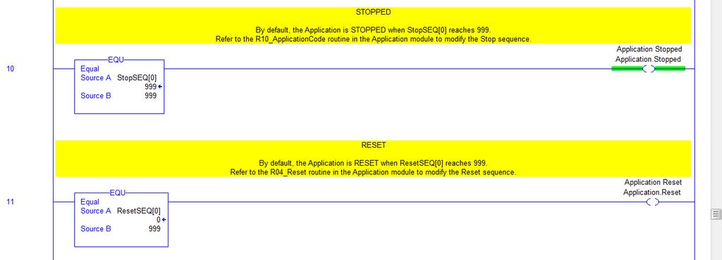
141 DMAT Application Status Rungs 141 of 147


142 Application Modules The application modules contain all of the application specific code. This is where a majority of the customizing is expected to occur and is essentially a programming space where you spend a significant portion of your efforts to develop proprietary logic specific to your application. In this example, application code is shown within the R10_ApplicationCode routine of the P02_Application program. In this example below, is only a part of the application code is shown for the DMAT assembly application. 142 of 147


143 143 of 147
144 Device Modules Device modules contain all of the logic to control the essential functions required by the device. For this DMAT example, we are using the PowerFlex 753 / 755 HMI faceplate and AOI instruction which has preprogrammed start, stop, speed reference, Accel and Decel times. This logic reduces the programming effort required by most applications providing more time for the proprietary logic needed for the application. Typically, the device module consists of a physical drive, but could also consist of a virtual or feedback-only axis. Device modules can also consist of multiple devices, for example, a drive and perhaps a feedback device, for example, a sensor. Device Module Tags The application and individual device modules interact with each other via device specific control tags that include both command and status information. The control tags consist of these data types. All of the data types listed above can be modified to fit specific needs of your application. However, modifications to the data types could have an impact on the device module and/or other preprogrammed logic, especially during import of additional device modules. For example, the UDT_ServoCtrl data type that is used by the integrated motion drives (CIP Motion and sercos interface based drives) consists of these tags. 144 of 147


145 CIP Motion UDT_ServoCtrl Tag Listing UDT_ServoCtrl Tag The user-defined type for the Kinetix 300 drives and the add-on defined data type for the PowerFlex drives serve similar function as the UDT_ServoCtrl data type, however their layouts differ. Refer to the specific data types for more information. 145 of 147

146 Device Module Control Logic In this example, the R03_Control routine for the P04_PF755_Drive device module initiates and/or clears the Reset and Abort sequences. It is the same for the R03_Control routine for the P03_PF525_Drive device module. 146 of 147
L09 - Drive Configuration & Programming Lab. For Classroom Use Only!
 L09 - Drive Configuration & Programming Lab For Classroom Use Only! Important User Information This documentation, whether, illustrative, printed, online or electronic (hereinafter Documentation ) is intended
Basic Drive Programming PowerFlex 755 Basic Start Up
 Basic Drive Programming PowerFlex 755 Basic Start Up PowerFlex 755 Basic Start Up for Speed Controlled Applications Contents Before you begin... 4 Tools... 4 About this lab... 4 About the Demo... 4 Lab
Bus Regulation. PowerFlex 755 AC Drives. For Classroom Use Only!
 Bus Regulation PowerFlex 755 AC Drives For Classroom Use Only! Important User Information This documentation, whether, illustrative, printed, online or electronic (hereinafter Documentation ) is intended
For Classroom Use Only! Flying Start PowerFlex 755 AC Drives
 For Classroom Use Only! Flying Start PowerFlex 755 AC Drives Important User Information This documentation, whether, illustrative, printed, online or electronic (hereinafter Documentation ) is intended
L12 - Studio 5000 and Logix: Basics Lab. For Classroom Use Only!
 L12 - Studio 5000 and Logix: Basics Lab For Classroom Use Only! Important User Information This documentation, whether, illustrative, printed, online or electronic (hereinafter Documentation ) is intended
L01 - Effective Design Methods for Integrating Safety Using Logix Controllers. For Classroom Use Only!
 L01 - Effective Design Methods for Integrating Safety Using Logix Controllers For Classroom Use Only! Important User Information This documentation, whether, illustrative, printed, online or electronic
Product Compatibility and Download Center
 Product Compatibility and Download Center Important User Information This documentation, whether, illustrative, printed, online or electronic (hereinafter Documentation ) is intended for use only as a
Product Compatibility and Download Center
 Product Compatibility and Download Center Important User Information This documentation, whether, illustrative, printed, online or electronic (hereinafter Documentation ) is intended for use only as a
Size, Select and Configure Kinetix and PowerFlex Drives Using Motion Analyzer. For Classroom Use Only!
 Size, Select and Configure Kinetix and PowerFlex Drives Using Motion Analyzer For Classroom Use Only! Important User Information This documentation, whether, illustrative, printed, online or electronic
FlexPak 3000 Drive Operator Interface Module (OIM) User s Guide
 User s Guide") FlexPak 3000 Drive Operator Interface Module (OIM) User s Guide Instruction Manual D2-3344 The information in this manual is subject to change without notice. Throughout this manual, the following notes
FlexPak 3000 Drive Operator Interface Module (OIM) User s Guide Instruction Manual D2-3344 The information in this manual is subject to change without notice. Throughout this manual, the following notes
GV3000/SE General Purpose (Volts/Hertz) and Vector Duty AC Drive, HP, 230V AC
 and Vector Duty AC Drive, HP, 230V AC") Software Start-Up and Reference Manual D2-3416-2 GV3000/SE General Purpose (Volts/Hertz) and Vector Duty AC Drive, 30-100 HP, 230V AC Version 6.04 Important User Information Solid-state equipment has operational
Software Start-Up and Reference Manual D2-3416-2 GV3000/SE General Purpose (Volts/Hertz) and Vector Duty AC Drive, 30-100 HP, 230V AC Version 6.04 Important User Information Solid-state equipment has operational
L14 - Speed Integration with Ethernet-enabled CENTERLINE MCCs, Rockwell Software Studio 5000 and IntelliCENTER Software
 L14 - Speed Integration with Ethernet-enabled CENTERLINE MCCs, Rockwell Software Studio 5000 and IntelliCENTER Software For Classroom Use Only! Important User Information This documentation, whether, illustrative,
GV3000/SE Operator Interface Module (OIM) User Guide Version 2.0 M/N 2RK3000
 User Guide Version 2.0 M/N 2RK3000") GV3000/SE Operator Interface Module (OIM) User Guide Version 2.0 M/N 2RK3000 Instruction Manual D2-3342-2 The information in this manual is subject to change without notice. Throughout this manual, the
GV3000/SE Operator Interface Module (OIM) User Guide Version 2.0 M/N 2RK3000 Instruction Manual D2-3342-2 The information in this manual is subject to change without notice. Throughout this manual, the
Sizing PlantPAx System Architecture for Optimal Performance. For Classroom Use Only!
 Sizing PlantPAx System Architecture for Optimal Performance For Classroom Use Only! Important User Information This documentation, whether, illustrative, printed, online or electronic (hereinafter Documentation
GuardLogix Controller to Kinetix 6000 Drive with Safe-Off using EtherNet/IP CompactBlock Guard I/O Module
 Safety Application Example GuardLogix Controller to Kinetix 6000 Drive with Safe-Off using EtherNet/IP CompactBlock Guard I/O Module Safety Rating: SIL3/Category 3 (also see SIL3/CAT4 section), according
Using the 20-HIM-A6 HIM with the LiquiFlo 2.0 AC Drive 20-HIM-A6 Firmware Revision Number or Later
 User Manual Using the 20-HIM-A6 HIM with the Liquilo 2.0 AC Drive 20-HIM-A6 irmware Revision Number 2.001 or Later Topic Page Additional Resources 1 Getting Started 1 Installing and Removing the HIM 2
L05 - PowerFlex Drives Configuration & Programming
 - 5058-CO900H L05 - PowerFlex Drives Configuration & Programming PUBLIC Lab Description This is a training lab on PowerFlex 525 compact AC drive and the PowerFlex 755 AC Drive While you re here, you will:
Studio 5000 Architect Getting Results Guide
 Getting Results Studio 5000 Architect Getting Results Guide Rockwell Automation Publication ARCH-GR001I-EN-E Supersedes Publication ARCH-GR001H-EN-E Important user information Read this document and the
PowerFlex 520-Series AC Drives. The Next Generation of Powerful Performance. Flexible Control.
 PowerFlex 520-Series AC Drives The Next Generation of Powerful Performance. Flexible Control. PowerFlex 520-Series AC Drives The Next Generation of Powerful Performance. Flexible Control. The Allen-Bradley
Firmware Manual - EC Series Drives
 1 Firmware Manual - EC Series Drives Doc Ver 1.01 Firmware ver: EC series drives For installation details refer to Hardware Manual Safety: Read safety instruction in hardware manual before installation
1336-Series Drives to PowerFlex 750-Series Drives
 1336-Series Drives to PowerFlex 750-Series Drives 1336Plus 1336PlusII 1336Impact POWERFLEX 750 SERIES POWER CONNECTIONS TB1 ON 1336PLUS TB2 ANALOG SIGNALS AND RELAY FEEDBACK TB3 DIGITAL INPUTS FOR 1336
PowerMonitor 5000 Unit Catalog Number Upgrade
 Installation Instructions PowerMonitor 5000 Unit Catalog Number Upgrade Catalog Numbers 1426-MxE-xxx Topic Page Upgrade the Device Catalog Number with the ControlFLASH Utility 3 Determine Communication
User Manual. PowerFlex 525 Embedded EtherNet/IP Adapter
 User Manual PowerFlex 525 Embedded EtherNet/IP Adapter Important User Information Solid-state equipment has operational characteristics differing from those of electromechanical equipment. Safety Guidelines
ControlLogix Redundancy Update and Module Replacement Guidelines
 Reference Manual Original Instructions ControlLogix Redundancy Update and Module Replacement Guidelines Product Family ControlLogix 5570 Controllers Important User Information Read this document and the
DeviceNet Network Configuration
 User Manual DeviceNet Network Configuration 1756 ControlLogix, 1756 GuardLogix, 1769 CompactLogix, 1769 Compact GuardLogix, 1789 SoftLogix, Studio 5000 Logix Emulate Important User Information Solid-state
GV3000/SE 230 VAC 1-20 HP General Purpose (Volts/Hertz) and Vector Duty Drive Software Start-Up and Reference Manual Version 6.04
 and Vector Duty Drive Software Start-Up and Reference Manual Version 6.04") GV3000/SE 230 VAC 1-20 HP General Purpose (Volts/Hertz) and Vector Duty Drive Software Start-Up and Reference Manual Version 6.04 Instruction Manual D2-3387-4 The information in this manual is subject
GV3000/SE 230 VAC 1-20 HP General Purpose (Volts/Hertz) and Vector Duty Drive Software Start-Up and Reference Manual Version 6.04 Instruction Manual D2-3387-4 The information in this manual is subject
Position Control via HMI Connected Components Building Block. Quick Start
 Position Control via HMI Connected Components Building Block Quick Start Important User Information Solid state equipment has operational characteristics differing from those of electromechanical equipment.
PowerFlex 755 Drives (revision 4.002)
") Release Notes PowerFlex 755 Drives (revision 4.002) These release notes correspond to major revision 4, minor revision 2 of firmware for PowerFlex 755 drives. Introduction The following information is
Release Notes PowerFlex 755 Drives (revision 4.002) These release notes correspond to major revision 4, minor revision 2 of firmware for PowerFlex 755 drives. Introduction The following information is
PowerFlex 753 Drives (revision 8.002)
") Release Notes PowerFlex 753 Drives (revision 8.002) These release notes correspond to major revision 8, minor revision 2 of firmware for PowerFlex 753 drives. Introduction The following information is
Release Notes PowerFlex 753 Drives (revision 8.002) These release notes correspond to major revision 8, minor revision 2 of firmware for PowerFlex 753 drives. Introduction The following information is
PowerFlex 700H Drive Firmware (Revision )
") Release Notes PowerFlex 700H Drive Firmware (Revision 67.001) These release notes correspond to revision 67.001 of firmware for PowerFlex 700H drives. This document describes the differences between firmware
Release Notes PowerFlex 700H Drive Firmware (Revision 67.001) These release notes correspond to revision 67.001 of firmware for PowerFlex 700H drives. This document describes the differences between firmware
Quick Start. PowerFlex 750-Series AC Drives
 Quick Start PowerFlex 750-Series AC Drives Important User Information Read this document and the documents listed in the additional resources section about installation, configuration, and operation of
T62 - Next Generation of Compact AC Drives
 T62 - Next Generation of Compact AC Drives PUBLIC INFORMATION Rev 5058-CO900E 2 Agenda PowerFlex 520-Series Why the PowerFlex 527? PowerFlex 527 AC Drive Target Applications Application Benefits of PowerFlex
Micro800 Programmable Controllers: Getting Started with Motion Control Using a Simulated Axis
 Quick Start Micro800 Programmable Controllers: Getting Started with Motion Control Using a Simulated Axis Catalog Numbers Bulletin 2080-LC30, 2080-LC50 Important User Information Solid-state equipment
Logix5000 Control Systems: Connect a PanelView Plus Terminal over an EtherNet/IP Network
 Quick Start Logix5000 Control Systems: Connect a PanelView Plus Terminal over an EtherNet/IP Network Catalog Numbers Logix5000 Controllers, 2711P PanelView Plus Terminals Important User Information Solid-state
1336 PLUS II Quick Start Guide
 1336 PLUS II Quick Start Guide This Quick Start Guide summarizes the basic steps needed to install, start-up and program the 1336 PLUS II Adjustable Frequency AC Drive. The information provided Does Not
Color-Sensing Connected Components Building Block. Quick Start
 Color-Sensing Connected Components Building Block Quick Start Important User Information Solid state equipment has operational characteristics differing from those of electromechanical equipment. Safety
LiquiFlo 1.5 AC General Purpose (Volts/Hertz) and Vector Duty Drive Software Start-Up and Reference Manual Version 1.2
 and Vector Duty Drive Software Start-Up and Reference Manual Version 1.2") LiquiFlo 1.5 AC General Purpose (Volts/Hertz) and Vector Duty Drive Software Start-Up and Reference Manual Version 1.2 Instruction Manual D2-3495 The information in this manual is subject to change without
LiquiFlo 1.5 AC General Purpose (Volts/Hertz) and Vector Duty Drive Software Start-Up and Reference Manual Version 1.2 Instruction Manual D2-3495 The information in this manual is subject to change without
Micro800 Programming Basics. For Classroom Use Only!
 Micro800 Programming Basics For Classroom Use Only! Important User Information This documentation, whether, illustrative, printed, online or electronic (hereinafter Documentation ) is intended for use
Micro800 Controllers Starter Pack Quick Start
 Quick Start Micro800 Controllers Starter Pack Quick Start Catalog Numbers Bulletin 2080-LC20, 2080-LC30, 2080-LC50 Important User Information Read this document and the documents listed in the additional
PowerMonitor 1000 Unit Catalog Number Upgrade
 Installation Instructions PowerMonitor 1000 Unit Catalog Number Upgrade Catalog Numbers 1408-UPT1-E3, 1408-UPT2-E3, 1408-UPE1-E3, 1408-UPE2-E3, 1408-UP485-ENT, 1408-UPT3-E3 Topic Important User Information
User Manual. PowerFlex 25-COMM-E2P Dual-Port EtherNet/IP Adapter
 User Manual PowerFlex Dual-Port EtherNet/IP Adapter Chapter 1 Getting Started The Dual-port EtherNet/IP adapter is a communication option intended for installation into a PowerFlex 520-series drive. The
Simple Motion Control Connected Components Building Block. Quick Start
 Simple Motion Control Connected Components Building Block Quick Start Important User Information Solid state equipment has operational characteristics differing from those of electromechanical equipment.
Pump Station Controller. Quick Start
 Pump Station Controller Quick Start Important User Information Solid state equipment has operational characteristics differing from those of electromechanical equipment. Safety Guidelines for the Application,
CS3000 MMI SW-Version 6.1 Control and Configuration Software for FlexPak3000 V , GV3000 V and Liqui-Flo. Instruction Manual
 CS3000 MMI SW-Version 6.1 Control and Configuration Software for FlexPak3000 V2.0-4.3, GV3000 V2.0-6.0 and Liqui-Flo Instruction Manual Manual P/N: 899.05.84 Firmware P/N: 788.05.30 User Manual: 49 1307e
PowerFlex 700 AC Drive with Vector Control Option, Firmware Revision
 Release Notes PowerFlex 7 AC Drive with Vector Control Option, Firmware Revision. Topic Page Enhancements Corrected Anomalies 3 Determine Firmware Revision Level 4 Firmware Upgrade Procedure 4 These release
LiquiFlo AC General Purpose (Volts/Hertz) and Vector Duty Drive Software Start-Up and Reference Manual Version 6.4
 and Vector Duty Drive Software Start-Up and Reference Manual Version 6.4") LiquiFlo AC General Purpose (Volts/Hertz) and Vector Duty Drive Software Start-Up and Reference Manual Version 6.4 Instruction Manual D2-3410-7 The information in this manual is subject to change without
LiquiFlo AC General Purpose (Volts/Hertz) and Vector Duty Drive Software Start-Up and Reference Manual Version 6.4 Instruction Manual D2-3410-7 The information in this manual is subject to change without
Variable Frequency Drive Design Guidelines
 Variable Frequency Drive Design Guidelines The Variable Frequency Drive Design Standard provides design criteria and specifications used in the procurement and application of variable frequency drives
ELECTRICAL ENGINEERING TECHNOLOGY Introduction to RSLogix 5000 and the Compact Logix PLC
 KENNESAW STATE UNIVERSITY ECET 4530 ELECTRICAL ENGINEERING TECHNOLOGY Introduction to RSLogix 5000 and the Compact Logix PLC Introduction: In this exercise you will setup, configure, program and operate
Using TLS3-GD2 Guardlocking Interlock with ArmorBlock Guard I/O and SmartGuard Controller
 Safety Application Example Using TLS3-GD2 Guardlocking Interlock with ArmorBlock Guard I/O and SmartGuard Controller Guardlocking with On-machine Components Safety Rating: Category 3, according to EN954-1
GuardLogix: Safety Gate Application with SensaGuard Switch
 Safety Application Example GuardLogix: Safety Gate Application with SensaGuard Switch Safety Rating: PLe, Cat. 4 to EN ISO 13849.1 2008 Introduction...2 Important User Information...2 General Safety Information...3
PanelView 800 HMI Terminals
 User Manual PanelView 800 HMI Terminals Catalog Numbers 2711R-T4T, 2711R-T7T, 2711R-T10T Important User Information Solid state equipment has operational characteristics differing from those of electromechanical
PowerFlex 525 DeviceNet Adapter
 User Manual PowerFlex 525 DeviceNet Adapter Catalog Number: 25-COMM-D Important User Information Solid-state equipment has operational characteristics differing from those of electromechanical equipment.
PlantPAx Logix Batch and Sequence Manager
 Reference Manual PlantPAx Logix Batch and Sequence Manager Version 4.0 Important User Information Read this document and the documents listed in the additional resources section about installation, configuration,
PowerFlex 700H Adjustable Frequency AC Drive. Programming Manual V1.xxx 5.002
 PowerFlex 7H Adjustable Frequency AC Drive Programming Manual V.xxx 5.2 Important User Information Solid state equipment has operational characteristics differing from those of electromechanical equipment.
GuardLogix: TLS Guardlocking Application
 Safety Application Example GuardLogix: TLS Guardlocking Application Safety Rating: PLd, Cat. 3 to EN ISO 13849.1 2008 Introduction... 2 Important User Information... 2 General Safety Information... 3 Description...
Simple Package Measurement Connected Components Building Block. Quick Start
 Simple Package Measurement Connected Components Building Block Quick Start Important User Information Solid state equipment has operational characteristics differing from those of electromechanical equipment.
Allen-Bradley Motors
 Installation Instructions Firmware Update Instructions for Ethernet, Enhanced and ControlNet PLC-5 Programmable Controllers Purpose Firmware Update Kit Contents Hardware and Software Requirements This
GuardLogix: Dual Zone Gate Protection with E-stop and Trojan Interlock Switch
 Safety Application Example GuardLogix: Dual Zone Gate Protection with E-stop and Trojan Interlock Switch Safety Rating: PLd, Cat. 3 to EN ISO 13849.1 2008 Introduction... 2 Important User Information...
Adjustable Frequency AC Drive
 Adjustable Frequency AC Drive Important User Information Solid state equipment has operational characteristics differing from those of electromechanical equipment. Safety Guidelines for the Application,
PowerFlex 753 Drives (revision 9.002)
") Release Notes PowerFlex 753 Drives (revision 9.002) These release notes correspond to major revision 9, minor revision 2 of firmware for PowerFlex 753 drives. Introduction The following information is
Release Notes PowerFlex 753 Drives (revision 9.002) These release notes correspond to major revision 9, minor revision 2 of firmware for PowerFlex 753 drives. Introduction The following information is
ACS850 User s Guide ACS850 Control Panel
 ACS850 User s Guide ACS850 Control Panel ACS850 Control Panel User s Guide 3AUA0000050277 Rev A EN EFFECTIVE: 02.01.2009 2009 ABB Oy. All Rights Reserved. 5 Table of contents Table of contents About the
PowerFlex 753 Drives (revision )
") Release Notes PowerFlex 753 Drives (revision 10.003) These release notes correspond to major revision 10, minor revision 3 of firmware for PowerFlex 753 drives. Introduction The following information is
Release Notes PowerFlex 753 Drives (revision 10.003) These release notes correspond to major revision 10, minor revision 3 of firmware for PowerFlex 753 drives. Introduction The following information is
Distributed Power System SA3100 Drive Configuration and Programming
 Distributed Power System SA3100 Drive Configuration and Programming Instruction Manual S-3056-1 Throughout this manual, the following notes are used to alert you to safety considerations:! ATTENTION: Identifies
User Manual. PowerFlex 20-HIM-A6 and 20-HIM-C6S HIM (Human Interface Module) FRN 1.xxx - 2.xxx
 FRN 1.xxx - 2.xxx") User Manual PowerFlex 20-HIM-A6 and 20-HIM-C6S HIM (Human Interface Module) FRN 1.xxx - 2.xxx Important User Information Solid-state equipment has operational characteristics differing from those of electromechanical
User Manual PowerFlex 20-HIM-A6 and 20-HIM-C6S HIM (Human Interface Module) FRN 1.xxx - 2.xxx Important User Information Solid-state equipment has operational characteristics differing from those of electromechanical
PanelView 800 HMI Terminals
 User Manual PanelView 800 HMI Terminals Catalog Numbers 2711R-T4T, 2711R-T7T, 2711R-T10T Important User Information Solid state equipment has operational characteristics differing from those of electromechanical
PowerFlex 70 Safe-Off Control EtherNet/IP Guard I/O Safety Module and GuardLogix Integrated Safety Controller
 Safety Application Example PowerFlex 70 Safe-Off Control EtherNet/IP Guard I/O Safety Module and GuardLogix Integrated Safety Controller Safety Rating: Category 3 (also see Achieving a Cat. 4 Safety Rating)
Teaching Color-Sensing Connected Components Building Block. Quick Start
 Teaching Color-Sensing Connected Components Building Block Quick Start Important User Information Solid state equipment has operational characteristics differing from those of electromechanical equipment.
PowerFlex 20-HIM-A6 and 20-HIM-C6S HIM Firmware Revision 1.006
 Release Note PowerFlex 20-HIM-A6 and 20-HIM-C6S HIM Firmware Revision 1.006 This release note describes major revision 1, minor revision 6 of firmware for PowerFlex 20-HIM-A6 and 20-HIM-C6S HIMs (Human
Power Connections: Basic Wiring:
 Power Connections: The CFW10 Quick Start Guide is a supplement to help get the CFW10 started quickly using the most common installation and configuration options. This CFW10 Quick Start Guide is not meant
Solar Combiner Enclosure
 Installation Instructions Solar Combiner Enclosure Catalog Numbers 1000-SB006, 1000-SB012 Topic Page Description 1 Important Safety Instructions 3 Nameplate Data 4 Planning for Installation 4 Install the
For normal duty, design the VFD voltage level at 480 Volt, 3 Phase, 60 Hertz. (In Canada, 600 Volt, 3 Phase, 60 Hertz.)
") Introduction The Variable Frequency Drive Design Guidelines provides design criteria and specifications used in the procurement and application of variable frequency drives (VFDs). Table of Contents 1.
Introduction The Variable Frequency Drive Design Guidelines provides design criteria and specifications used in the procurement and application of variable frequency drives (VFDs). Table of Contents 1.
Quick Start Guide For GVX9000 AF Drives
 Quick Start Guide For GVX9000 AF Drives June 2006 New Information 5011646300 00GQ MN04000002E June 2006 Step 1 Wiring Hazardous High Voltage HIGH VOLTAGE! Motor control equipment and electronic controllers
PowerFlex 755 Drives (revision )
") Release Notes These release notes correspond to major revision 10, minor revision 3 of firmware for PowerFlex 755 drives. Introduction The following information is included in this document: For information
Release Notes These release notes correspond to major revision 10, minor revision 3 of firmware for PowerFlex 755 drives. Introduction The following information is included in this document: For information
Catalog Numbers 9308-RSFB64ENE, 9308-RSFB256ENE, 9308-RSFB1024ENE
 Release Notes RSFieldbus Software Catalog Numbers 9308-RSFB64ENE, 9308-RSFB256ENE, 9308-RSFB1024ENE Topic Page Important User Information 2 Before You Begin 3 Software Requirements 4 Install the Software
Introduction to Micro800 Motion. For Classroom Use Only!
 Introduction to Micro800 Motion For Classroom Use Only! Important User Information This documentation, whether, illustrative, printed, online or electronic (hereinafter Documentation ) is intended for
Unidrive M200, M201 (Frame 1 to 4) Quick Start Guide
 Quick Start Guide") This guide is intended to provide basic information required in order to set-up a drive to run a motor. Please refer to the Unidrive M200 / M20 User Guide which is available to download from www.controltechniques.com/user
This guide is intended to provide basic information required in order to set-up a drive to run a motor. Please refer to the Unidrive M200 / M20 User Guide which is available to download from www.controltechniques.com/user
EtherNet/IP Communications Module
 EtherNet/IP Communications Module M/N RECOMM-ENET Firmware Version 2.xxx Firmware Version 3.xxx Instruction Manual D2-3510-1 The information in this manual is subject to change without notice. Throughout
SequenceManager Controls
 Reference Manual SequenceManager Controls 1756 ControlLogix, 1756 GuardLogix, 1769 CompactLogix, 1769 Compact GuardLogix, 1789 SoftLogix, Studio 5000 Logix Emulate Important user information Read this
Logix5000 Controllers Function Block Diagram
 Logix5000 Controllers Function Block Diagram Catalog Numbers 1756 ControlLogix, 1769 CompactLogix, 1789 SoftLogix, 1794 FlexLogix, PowerFlex 700S with DriveLogix Programming Manual Important User Information
PanelView Component HMI Terminals
 User Manual PanelView Component HMI Terminals Catalog Numbers 2711C-F2M, 2711C-K2M, 2711C-T3M, 2711C-K3M, 2711C-T4T, 2711C-T6M, 2711C-T6C, 2711C-T6T, 2711C - T10C Important User Information Solid state
Using GuardShield Light Curtains (Safe 4, Micro 400, or 440L), with ArmorBlock Guard I/O and SmartGuard Controller
, with ArmorBlock Guard I/O and SmartGuard Controller") Safety Application Example Using GuardShield Light Curtains (Safe 4, Micro 400, or 440L), with ArmorBlock Guard I/O and SmartGuard Controller Light Curtain with On-machine Components Safety Rating: Category
Safety Application Example Using GuardShield Light Curtains (Safe 4, Micro 400, or 440L), with ArmorBlock Guard I/O and SmartGuard Controller Light Curtain with On-machine Components Safety Rating: Category
Logix5000 Controllers Nonvolatile Memory Card
 Programming Manual Logix5000 Controllers Nonvolatile Memory Card 1756 ControlLogix, 1756 GuardLogix, 1769 CompactLogix, 1769 Compact GuardLogix, 1789 SoftLogix, 5069 CompactLogix, Studio 5000 Logix Emulate
Optidrive Applications Support Library
 Optidrive Applications Support Library Application Note Title AN-ODE-3-038 Related Products Optidrive E3 Overview Level 3 Modbus RTU Control and Register Mapping 1 Fundamental - No previous experience
PanelView 800 HMI Terminals
 User Manual PanelView 800 HMI Terminals Catalog Numbers 2711R-T4T, 2711R-T7T, 2711R-T10T Industrial automation Elincom Group European Union: www.elinco.eu Russia: www.elinc.ru Important User Information
ControlLogix SIL2 System Configuration
 ControlLogix SIL2 System Configuration Using RSLogix 5000 Subroutines Application Technique (Catalog Numbers 1756 and 1492) Important User Information 8 / 2011 Solid state equipment has operational characteristics
The Allen-Bradley PowerFlex Family of AC Drives
 PowerFlex Tomorrow s World-Class AC Drive Technology The Allen-Bradley PowerFlex Family of AC Drives Setting a new standard for powerful performance and flexible control to meet the global needs of virtually
Kinetix 6000 Axis Module and Shunt Module
 Installation Instructions Kinetix 6000 and Shunt Module Catalog Numbers 2094-AMxx, 2094-BMxx 2094-AMxx-S, 2094-BMxx-S 2094-BSP2 Topic Page About This Publication 1 Important User Information 2 Before You
CENTERLINE 2100 Motor Control Centers EtherNet/IP Network Adapter
 User Manual CENTERLINE 2100 Motor Control Centers EtherNet/IP Network Adapter Catalog Numbers 2100-ENET Series A FRN 1.XXX Important User Information Solid-state equipment has operational characteristics
Architecture Scalability Using the Kinetix 300 Indexing Servo Drive
 Architecture Scalability Using the Kinetix 300 Indexing Servo Drive For Classroom Use Only! (RA-11-L09) (IA-11-L13) Publication Number -- Date Architecture scalability using the Kinetix 300 Indexing Servo
EQ5 SERIES Quick Start Guide for Constant Torque Applications
 EQ5 SERIES Quick Start Guide for Constant Torque Applications PN EQ5QSCT, Revision: 0.02, April 4 th 2009 EQ5 Drive Quick Start Guide for Constant Torque Applications Contents Page Introduction... 3 1.
L07 - Micro800 PLC Programming with Connected Components Workbench Software. For Classroom Use Only!
 L07 - Micro800 PLC Programming with Connected Components Workbench Software For Classroom Use Only! Important User Information This documentation, whether, illustrative, printed, online or electronic (hereinafter
ADXL Series SIMPLE, EFFICIENT AND SAFE MOTOR CONTROL
 SOFT STARTERS ADXL Series SIMPLE, EFFICIENT AND SAFE MOTOR CONTROL Simplicity The ADXL series of soft starters is equipped with a backlit LCD icon display and NFC connectivity for quick and easy configuration,
Using a Guard Locking Interlock Switch and Light Curtains with DeviceNet Guard I/O and a GuardLogix Controller
 Safety Application Example Using a Guard Locking Interlock Switch and Light Curtains with DeviceNet Guard I/O and a GuardLogix Controller Safety Rating: Category 3, according to EN954-1 Introduction...
DeviceNet Communications
 DeviceNet Communications For PanelView Plus and PanelPlus CE Terminals 2711P User Manual Important User Information Solid state equipment has operational characteristics differing from those of electromechanical
Import/Export Project Components. Programming Manual
 Import/Export Project Components Programming Manual Important User Information Solid state equipment has operational characteristics differing from those of electromechanical equipment. Safety Guidelines
Advanced PLC Topics for Micro800 Controllers with Motion Capabilities and CIP Messaging Functionality. For Classroom Use Only!
 Advanced PLC Topics for Micro800 Controllers with Motion Capabilities and CIP Messaging Functionality For Classroom Use Only! Important User Information This documentation, whether, illustrative, printed,
PowerFlex 750-Series AC Drives
 PowerFlex -Series AC Drives Cost-effective Solution Designed for Ease of Use, Integration & Application Flexibility. The Allen-Bradley PowerFlex -Series of AC Drives is aimed at maximizing your investment
Using the Kinetix 300 Drive
 Using the Kinetix 300 Drive Using the Kinetix 300 Drive: Hands-On Lab Traiiniing Lab Manuall USING THE KINETIX 300 DRIVE 7 ABOUT THIS HANDS-ON LAB 7 LAB MATERIALS 7 DOCUMENT CONVENTIONS 8 BEFORE YOU
Logix5000 Controllers Produced and Consumed Tags
 Logix5 Controllers Produced and Consumed Tags Catalog Numbers 1756 ControlLogix, 1756 GuardLogix, 1768 Compact GuardLogix, 1769 CompactLogix, 1789 SoftLogix, PowerFlex with DriveLogix Programming Manual
User Manual. PowerFlex ENETR Dual-port EtherNet/IP Option Module Firmware Revision Number 1.xxx
 User Manual PowerFlex 20-750-ENETR Dual-port EtherNet/IP Option Module Firmware Revision Number 1.xxx Important User Information Solid-state equipment has operational characteristics differing from those