SilverLeaf RV-C Control System Training Manual
|
|
|
- Jerome Carter
- 5 years ago
- Views:
Transcription


1 2013 SilverLeaf RV-C Control System Training Manual Newmar Corporation Revised Jan. 2013
2

3 Newmar SilverLeaf RV-C Control System Operation/Set-UP Manual SCREEN ACCESS Please be aware that not all of the following screens are available to the end user! Some configuration screens require a password for access. Password protected screens contain control settings that should only be changed by qualified individuals! Changing these control settings to an improper setting can adversely affect the operation of the control system and may cause damage to the coach! The following is a list of the control and system status screens available on the Newmar SilverLeaf Control System Touch Screen Display. SYSTEM SPLASH SCREEN The Splash Screen is displayed momentarily on system power up. This screen can also be selected for display as one of the screen saver selections found in the monitor configuration. Page 1

 Temp Button (Standard Control) Pressing the Temp Button selects a screen that displays the outside ambient temperature.")
4 HOME SCREEN Every control function can be accessed by pressing one of the Buttons on the Home Screen. The Home Screen also displays system status and warnings in order of priority. The following items are displayed and/or controlled from this screen: HOME SCREEN WITH FLOOR HEAT OPTION Water Button Pressing this button selects the Water Control Screen. (see Water Control Screen) Climate Button Pressing this button selects the Climate Control Screens. (see Climate Control Screen) Temp Button (Standard Control) Pressing the Temp Button selects a screen that displays the outside ambient temperature. (see Temp Screen) BUTTON FUNCTIONS Home Button Pressing this Button returns you to the Home screen from the other control screens. The Home Button is not highlighted and is only operational from the other screens. AC Power Button Pressing this Button selects the AC Power Screen. (see AC Power Screen) DC Power Button Pressing this Button selects the DC Power Screen. (see DC Power Screen) Floor Button (Floor Heat Option) When the Floor Heat option is installed, the Floor Button will be displayed in place of the Temp Button. Pressing the Floor Button selects the Floor Heat Control Screen. This button is only displayed if the control system is configured for floor heat. (see Floor Heat Control Screen) Features Button Pressing this button will select the Features Screens. (see Features Screens) Genset Button Pressing this button selects the Genset Screen. (see Genset Screen) Page 2
5 Genset Button (Top Center) Pressing this button will manually start and stop the generator. The button indicator is highlighted when the generator is running. This button works the same as the Dash and other remote switches. AUTOFILL Button Pressing this button will turn on the Auto Fill feature. The button indicator is highlighted when the Auto Fill is on. PUMP Button pressing this button will turn the Water Pump on and off. The button indicator is highlighted when the pump is powered. AUTOGEN Button Pressing this button will select the AGS screens. The button indicator is highlighted when the Auto Charger is enabled. (see AGS Screens below) Block Heater Button Pressing this button toggles the Block Heater relay on/off. The button indicator is highlighted yellow when the load is being shed and blue when on. STATUS DISPLAYS Overall System Status - OK if no errors or warnings are present. Warnings and Errors will be displayed in this area in order of priority. Date/Outside Temperature/Time The system date, outside temperature and time are displayed in this area. Tank Status The Fresh, and Holding tanks status is displayed as a percentage of Full. Both a bar graph representation and a numerical percentage are displayed. DC Voltage Both the House Battery voltage and the Chassis Battery Voltage are displayed. There is also a Lightning Bolt icon that will illuminate when the isolator relay (Charge Bridge) is energized and connecting both battery systems together. AC Power Source, Voltage and Current The AC Power Source (Shore/Generator/Inverter), as well as, the Voltage and Current (Amperage) for both AC power legs are displayed. Page 3


 MANAGEMENT SCREEN The Load Management Screen displays the Shore Power Phase setting (Single Phase 30 Amps and less Service, Dual Phase 50 Amp Service) and allows you to")
6 AC POWER SCREENS MAIN AC POWER SCREEN The AC Power Screen displays the AC Power Source, Line Voltage and Current (Amperage) usage, as well as, the AC Line Frequency (Hz). The Ac Power Source is displayed for Shore Power; Generator or Inverter Power. The AC Amperage values are displayed both numerically and with horizontal bar graphs. The AC Voltage values are displayed numerically. The AC Line Frequency is displayed in Hertz (Hz). This screen also displays the maximum charge draw amps setting value, as well as, the inverter status. The Load Shed Management screen is selected from the Load Shed Button located on this screen. The Inverter can also be turned on and off from this screen, via the blank button to the right of the Inverter Status display. AC POWER SCREENS LOAD (SHED) MANAGEMENT SCREEN The Load Management Screen displays the Shore Power Phase setting (Single Phase 30 Amps and less Service, Dual Phase 50 Amp Service) and allows you to change between the phase selections using the Change Button. The current Amp draw is displayed for both legs on this screen. The Load Status screen is selected from the Loads Button. The Load Settings Screen is selected from the Settings Button. AC POWER SCREENS LOAD STATUS SCREEN The Load Status Screen displays the electrical Shed status of all the AC powered devices that are controlled by the control system. This screen also displays the AC voltage and amperage usage for both power legs Page 4
 50 Amp AC power based on the available AC power source.")
7 AC POWER SCREENS LOAD SETTING SCREEN 1 The first Load Setting screen configures the following settings: Phase Detection Manual / Automatic Set to Manual for standard Transfer Switch. Set to Automatic for RV-C Transfer Switch. A RV-C Transfer Switch has the capability of automatically detecting Dual Phase (240 VAC) 50 Amp AC power based on the available AC power source. Default Phase Single Phase / Dual Phase Selects the default Phase setting for the Load Shedding function. Capacity - Single Phase (Amperage) This setting sets the Load Shedding Amperage value for the Single Phase selection. Capacity Dual Phase (Amperage) This setting sets the Load Shedding Amperage value for the Dual Phase selection. This should normally be set 50 Amps. AC POWER SCREENS LOAD SETTING SCREEN 2 The second Load Setting screen configures the following settings: Capacity - Dual Phase (Amperage) This setting sets the Load Shedding Amperage value for the Dual Phase selection. This should normally be set 50 Amps. Load Shedding Enabled / Disabled Load Shedding Enabled allows the control system to shed (turn off) system configured AC powered devices in order to maintain a maximum phase capacity AC amperage usage. Generator Settling Enabled / Disabled This setting should be set to Enabled for proper Auto Gen operation. Charger 1 Shedding Enabled / Disabled This setting determines if the Battery Charger should be shed (turned off) with the other Load Shedding devices. Page 5


8 DC POWER SCREENS MAIN DC POWER SCREEN The Main DC Power Screen displays the Inverter / Charger status and allows access to the Magnum Setting Screens The Battery Icon has a vertical bar graph that indicates the battery charge level. The battery voltage value is displayed directly below the icon. The arrows between the Battery and Inverter Icons indicate the direction of the DC current flow. The DC current (amperage) value is displayed below the arrows. The Inverter/ Charger status is displayed inside the Inverter Icon. DC POWER SCREENS MAGNUM SETTINGS SCREEN 1 The first Magnum Setting screen configures the following settings: Inverter Status On / Off / Standby Charger Status On / Off / Standby Max Charging Current ( Amperage) This is the maximum amount of current the charger can output. Load Sense Power ( Wattage) This is the Power Level (Search Watts Setting) required to activate (wake up) the inverter. DC POWER SCREENS MAGNUM SETTINGS SCREEN 2 The second Magnum Setting screen configures the following settings: Charger Status On / Off / Standby Max Charging Current ( Amperage) This is the maximum amount of current the charger can output. Load Sense Power ( Wattage) This is the Power Level (Search Watts Setting) required to active (wake up) the inverter. Max Charger Rate (Percentage) This is the maximum % of AC current (amperage) used to recharge the batteries. Page 6


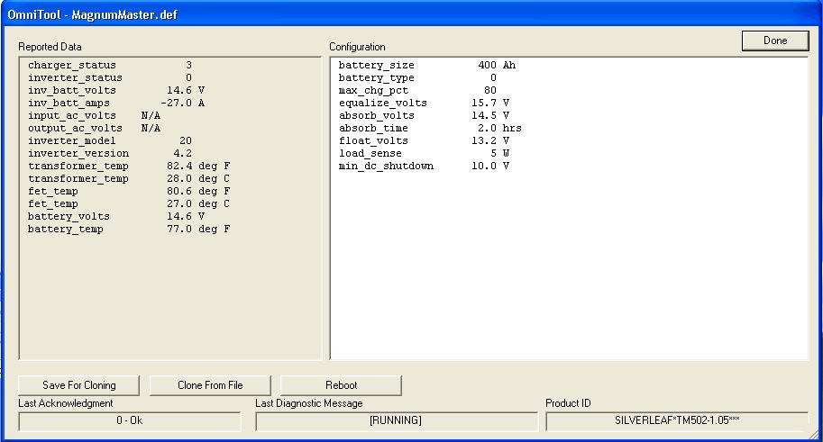
9 DC POWER SCREENS MAGNUM STATUS SCREEN The DC Power (Settings) Magnum Status Screen displays the following Status Values: Magnum Model/Version This value is read from the inverter via the Inverter Module. Battery Temperature This value is read from the inverter battery temperature sensor via the Inverter Module. Internal Temperature This value is read from the inverter via the inverter Module. FET Temperature This value is read from the inverter via the Inverter Module. DC POWER SCREENS MAGNUM ADVANCED SETTINGS SCREEN ACCESS The Password Access Screen is displayed to provide access to advanced system configuration screens. The advanced configuration screens contain control settings that should only be changed by qualified individuals. Changing these control settings to an improper setting can adversely affect the operation of the control system and may cause damage to the coach. DC POWER SCREENS MAGNUM ADVANCED SETTINGS SCREEN 1 The Magnum Advanced Settings Screen has the following Configuration Values: Low Voltage Shutdown ( DC Voltage) This setting is the low DC Voltage trigger point that will turn off the Inverter. Battery Type Flooded / Gel / AGM / AGM2 This should be set to match the physical battery type. Battery Rating (AH) This should be set to match total house battery power capacity Equalization Volts ( DC Voltage) This setting should match the manufacturer setting for the battery type. Page 7
 trigger point that will turn off the charger and turn the inverter on. Absorption Volts (DC Voltage) This is the DC Voltage that will be output when the charger is in Absorption Mode.")

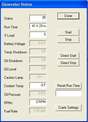
10 DC POWER SCREENS MAGNUM ADVANCED SETTINGS SCREEN 2 The Magnum Advanced Settings Screen has the following Configuration Values: Low AC Volts ( AC Voltage) This setting is the low AC Voltage (Brown Out) trigger point that will turn off the charger and turn the inverter on. Absorption Volts (DC Voltage) This is the DC Voltage that will be output when the charger is in Absorption Mode. Absorption Time (Hr) This is the amount of time that the charger will stay in Absorption Mode. Float Volts (DC Voltage) This is the DC Voltage that will be output when the charger is in Float Mode. GENSET SCREEN The Genset Screen displays the current Generator Status and control system run time. Note: The system generator run time can be set to match the physical generator hour meter using the OnmiScope Service Tool. The Start and Stop Buttons allow you to manually start and stop the generator. The Clear AGS Button allows you to clear the AGS Safety Lockout flag to reset the Auto Gen function. Page 8


11 WATER SCREEN ALL ELECTRIC EQUIPPED COACH The Water Screen on coaches equipped with the All Electric option displays the Fresh and Holding Tanks volume % full status. This screen also displays tank related faults, if any. The Water Pump Button turns the Water Pump on and off. The Auto Fill Button turns the Auto Fill function on and off. WATER SCREEN LP EQUIPPED COACH The Water Screen for a coach equipped with an LP tank, displays and controls the same functions as the All Electric Water Screen with the addition of the LP tank % full status. Page 9


12 CLIMATE SCREENS CLIMATE ALL SCREEN The Climate Screens are used to display the status and control the HVAC system. The Climate All Screen displays and provides global control of the Heating and Cooling for all of the HVAC zones. CLIMATE LVRM SCREEN Pressing the Heat or Cool Button activates all of the zones for the selected function at one time. The set points can be changed by pressing the associated up and down arrows or by dragging the associated circular temperature wheel to the desired set point. The Heat or Cool Buttons will highlight and Icons will be displayed when the functions are active. The Oasis control screen is only accessed from this screen. The Leave function is also accessed from this screen. The Leave function allows you to set different temperature set-points to control the HVAC system when you leave the coach. The Climate LvRm Screen displays the Heating and Cooling controls for Living Room zone. The Air Conditioner for cooling and both the Heat Pump and Oasis heating systems for the Living Room are controlled from this page. CLIMATE KITCH SCREEN The Climate Kitch Screen displays the Heating and Cooling controls for Kitchen zone. The Air Conditioner for cooling and only the Heat Pump for heating are controlled from the page. There is no Oasis heat available in this zone. Page 10


13 CLIMATE BATH SCREEN The Climate Bath Screen only controls the Bathroom Oasis heating system. There is no Air Conditioner or Heat Pump available for this zone, therefore the Cool Button is not displayed on this screen. CLIMATE BED SCREEN The Climate Bed Screen displays the Heating and Cooling controls for Bedroom zone. The Air Conditioner for cooling and both the Heat Pump and Oasis heating systems for the Bedroom are controlled from this page CLIMATE OASIS SCREEN The Oasis Screen is accessed from the Oasis Button displayed in the Climate All Screen. This screen controls the Oasis Burner and both AC Heating Elements. The Burner, AC #1 and AC #2 Buttons will highlight when active. This screen also displays the Oasis System operational Status and Faults. Page 11


14 TEMP SCREEN The Temp screen is accessed by pressing the Temp Button located on the Home Screen. This screen displays the Outside Air Temperature and only exists on systems without the optional Floor Heat. FLOOR SCREEN OPTIONAL FLOOR HEAT FLOOR HEAT with No Time Schedules The Floor Screen is accessed from the Floor Button located on the Main Screen. This screen controls the Floor Heat Zones by means of the slider bars or the up and down arrows and is only available on systems with the Floor Heat option.. The higher the number, the longer the time interval the heat mats are energized. This screen also contains icons that show the heating mat status. When the icon is red the mat is in heat cycle and when the icon is grey the heat function is on but the mat is between heating cycles FLOOR HEAT with Time Schedules Page 12

15 FEATURES SCREENS SCREEN 1 The Special Features Screens are used for system setup and diagnostics. The additional screens are accessed via the Up/Down Arrows. Special Features Screen 1 allows access to the following features: Clock Button Accesses the Clock Setup Screen System Diagnostics Button Accesses the System Diagnostics Screens Monitor Configuration Button Accesses the Monitor Configuration Screens Auto Genstart Button Accesses the Auto Genstart Configuration Screens FEATURES SCREENS SCREEN 2 FEATURES SCREENS SCREEN 3 Screen 2 allows access to the following features: View AC Power History Button Accesses the AC Power History Screen Auto Fill Configuration Button Accesses the Auto Fill Configuration Screens Warnings Configuration Button Accesses the Warnings Configuration Screens Tank Calibration Button Accesses the Tank Calibration Screens Screen 3 allows access to the following features: Climate Configuration Button Accesses the Climate Configuration Screens TM102 Configuration Button Accesses the TM102 Configuration Screen Component Versions Button Accesses the Component Versions Screen View Splash Screen Button Accesses the Splash Screen Page 13
16 FEATURES SCREENS FLOOR HEAT OPTION SCREEN 1 This screen is the same as the Base System Screens FEATURES FLOOR HEAT OPTION SCREEN 2 This screen has the optional Floor Heat Configuration Button Floor Heat Option Screen 2 allows access to the following features: View AC Power History Button Accesses the AC Power History Screen Auto Fill Configuration Button Accesses the Auto Fill Configuration Screens Floor Heat Configuration Button Accesses the Floor Heat Configuration Screen Warnings Configuration Button Accesses the Warnings Configuration Screens FEATURES FLOOR HEAT OPTION SCREEN 3 Floor Heat Option Screen 3 allows access to the following features: Tank Calibration Button Accesses the Tank Calibration Screens Climate Configuration Button Accesses the Climate Configuration Screens TM102 Configuration Button Accesses the TM102 Configuration Screen Component Versions Button Accesses the Component Versions Screen Page 14

17 FEATURES FLOOR HEAT OPTION SCREEN 4 Floor Heat Option Screen 4 allows access to the following features: Climate Configuration Button Accesses the Climate Configuration Screens TM102 Configuration Button Accesses the TM102 Configuration Screen Component Versions Button Accesses the Component Versions Screen View Splash Screen Button Accesses the Splash Screen Page 15


18 FEATURES CLOCK SCREENS The Clock Screen is accesses by pressing the Clock Button from The Features Screen. This screen displays the system time, outside temperature, system warnings/errors and allows you to access both the Alarm Clock and Countdown Timer functions. Pressing the Alarm Button will take you to the Alarm Clock page. On this page are two scroll bars that allow you to set the time of day for the alarm. This page also contains a Back Button that returns you to the previous page, as well as, an up/down arrow that allows you to toggle the alarm between the Off, Once Only or Every Day settings and a Set Clock Button. The Set Clock Button takes you to Monitor Configuration page 1, which allows you to set the system time. Pressing the Timer Button on the Clock Screen accesses the Countdown Timer screen. This screen has two scroll bars that allow you to set the countdown minutes and seconds. There is a Start Button on this screen that when pressed begins the countdown timer. This screen also has Back and Set Clock Buttons the same as the Alarm Clock screen.. Page 16


19 FEATURES SYSTEM DIAGNOSTICS SCREEN 1 The first Systems Diagnostics Screen is accessed by pressing the System Diagnostic Button located on the Features Screens or from the Prev Button located on second Systems Diagnostics Screen. This Screen displays any system faults present on the control system. FEATURES SYSTEM DIAGNOSTICS SCREEN 2 The second Systems Diagnostics Screen is accessed by pressing the Next Button located on the first Systems Diagnostics Screen or from the Prev Button located on third Systems Diagnostics Screen. This Screen displays communications status present on the control system. FEATURES SYSTEM DIAGNOSTICS SCREEN 3 The third Systems Diagnostics Screen is accessed by pressing the Next Button located on the second Systems Diagnostics Screen. This Screen displays additional communications status present on the control system. Pressing the Reset TM102 Button will reset the TM102 Module.. Page 17


20 FEATURES MONITOR CONFIGURATION SCREEN 1 The first Monitor Configuration Screen is accessed by pressing the Monitor Configuration Button located on the Features Screens or from the Prev Button located on second Monitor Configuration Screen. This Screen allows you to set the system time and date by pressing the associated up and Down Buttons. FEATURES MONITOR CONFIGURATION SCREEN 2 The second Monitor Configuration Screen is accessed by pressing the Next Button located on the first Monitor Configuration Screen or from the Prev Button located on third Monitor Configuration Screen. This Screen allows you to set the Day Time Display Setting by pressing the associated Up and Down Buttons. FEATURES MONITOR CONFIGURATION SCREEN 3 The third Monitor Configuration Screen is accessed by pressing the Next Button located on the second Monitor Configuration Screen or from the Prev Button located on fourth Monitor Configuration Screen. This Screen allows you to set the Night Time Display Settings by pressing the associated Up and Down Buttons. Page 18


21 FEATURES MONITOR CONFIGURATION SCREEN 4 The fourth Monitor Configuration Screen is accessed by pressing the Next Button located on the third Monitor Configuration Screen or from the Prev Button located on fifth Monitor Configuration Screen. This Screen allows you to set the following Monitor Functions: Button Color (Multiple Colors) Speaker (Sound) (None, Click or Beep) Speaker Volume (Off, Quiet, Normal or Loud) FEATURES MONITOR CONFIGURATION PASSWORD ACCESS The Password Access Screen is to provide access to advanced system configuration screens. These screens contain control settings that should only be changed by qualified individuals. FEATURES MONITOR CONFIGURATION SCREEN 5 The fifth Monitor Configuration Screen is accessed by pressing the Next Button located on the fourth Monitor Configuration Screen or from the Prev Button located on sixth Monitor Configuration Screen. This Screen allows you to set the following Display Settings: OEM Set to Newmar Video Camera Available Set to No (Controls the onboard video port) Waste System Installed Set to None Primary Furnace Installed Set to Oasis Basic Page 19

 Select Appropriate Setting using the Up / Down Arrows FEATURES MONITOR")
22 FEATURES MONITOR CONFIGURATION SCREEN 6 The sixth Monitor Configuration Screen is accessed by pressing the Next Button located on the fifth Monitor Configuration Screen or from the Prev Button located on seventh Monitor Configuration Screen. This Screen allows you to set the following Display Settings: Transfer Switch Type Set to Generic (Automatic if RV-C Communications Port Used) Inverter Model Set to Basic Magnum Floor Heat Mats Set to 0 if no Floor Heat Installed / Set to 3 if Floor Heat Installed Floor Heat Schedule (None, 2 Time Zone or 4 Time Zone) Select Appropriate Setting using the Up / Down Arrows FEATURES MONITOR CONFIGURATION SCREEN 7 The seventh Monitor Configuration Screen is accessed by pressing the Next Button located on the sixth Monitor Configuration Screen or from the Prev Button located on eighth Monitor Configuration Screen. This Screen allows you to set the following: Power management Installed Set to TM-250 Tile Heat System Installed Set to TM-220 Timed if Floor Heat is installed Autotemp AGS Installed Set to Autotemp for Temperature Autogen Control Block Heater Instance Set to 1 Page 20

 the display. Pressing the Reset to Defaults Button will set the display to the Factory Default settings.")
23 FEATURES MONITOR CONFIGURATION SCREEN 8 on the seventh Monitor Configuration Screen or from the Prev Button located on ninth Monitor Configuration Screen. This Screen allows you to set the following Display Settings: The eighth Monitor Configuration Screen is accessed by pressing the Next Button located Ambient Temp Instance Set to 249 Air Cond. Model Set to Dometic / TM510 Video Switch Instance Set to 0 FEATURES MONITOR CONFIGURATION SCREEN 9 on the seventh Monitor Configuration Screen. This Screen allows you to reset the display to the default settings or to restart (reboot) the display. Pressing the Reset to Defaults Button will set the display to the Factory Default settings. Resetting the display to the Factory Default settings will change any previously configured settings. Pressing the Restart HMS Button will reboot the display. The ninth Monitor Configuration Screen is accessed by pressing the Next Button located Generally a Restart is required after any setting changes have been made. In some cases the changes will take effect without a Restart. You must confirm that you wish to actually Reset the Monitor. Page 21

24 FEATURES AUTO GENSTART CONFIGURATION SCREENS AGS SCREEN 1 The first Autogen Configuration screen is accessed by pressing the Autogen Configuration Button located on the Features Configuration Screen or by pressing the Prev Button located on the second Autogen Configuration screen. This screen allows you to change the following settings: Safety Lock Clear / Locked When set to Locked this function will inhibit the generator from automatically starting. This function is set to Locked when the Generator Hood is open. Opening the hood actuates the Safety Lock Switch that is mounted to the generator mounting frame. It may be necessary to reset this setting after accessing the generator. Press the associated button to change the setting. Auto Charger Enabled / Disabled When Enabled, this function automatically starts and stops the generator based on the Auto Charger Configuration Settings (Battery Voltage, Max Run Time, Top Off Voltage and Top Off Run Time). Please note that the generator will not automatically start if Shore Power is present. Press the associated button to change the setting. Exerciser Enabled / Disabled When Enabled this function will automatically run the generator based on the Exerciser schedule settings on AGS screen 4. This function will automatically start the generator regardless of the Shore Power status. Press the associated button to change the setting. Auto Temp Enabled / Disabled When Enabled this function will automatically run the generator based on the Auto Temp schedule settings on AGS screen 5. The Auto Temp function will automatically start the generator based solely on temperature. This function is not triggered by any HVAC system commands. Please note that the generator will not automatically start if Shore Power is present. Press the associated button to change the setting. Page 22


25 FEATURES AUTO GENSTART CONFIGURATION SCREENS AGS SCREEN 2 The second Autogen Configuration screen is accessed by pressing the Next Button located on the first Autogen Configuration screen or by pressing the Prev Button located on the third Autogen Configuration screen. This screen allows you to change the following settings: Autocharger Start Volts (DC Voltage) If the Auto Charger function is Enabled, this setting determines the voltage level that will automatically start the generator. When the house battery voltage drops below this value for approximately 2 minutes the generator will automatically start and run until the charger goes into Float Mode or the Autocharger Max Run Time setting time has expired. Select value using the Up / Down Arrows Autocharger Max Run Time (min Time Set) This setting controls the maximum time the generator will run when started by the Autocharger function. Select value using the Up / Down Arrows Topoff Volts (DC Voltage) This setting determines the voltage level that will automatically start the generator based on the Topoff Run Time settings. Select value using the Up / Down Arrows Topoff Run Time (min Time Set) This setting determines the amount of time before Quiet Time begins to automatically start the generator, if the Auto Charger function is Enabled and the house battery voltage is below the Topoff Volts setting. If these conditions are met, the generator will automatically start and run until Quiet Time begins. Select value using the Up / Down Arrows FEATURES AUTO GENSTART CONFIGURATION SCREENS AGS SCREEN 3 The third Autogen Configuration screen is accessed by pressing the Next Button located on the second Autogen Configuration screen or by pressing the Prev Button located on the fourth Autogen Configuration screen. This screen controls the generator Quiet Time settings. During Quiet Time the generator is inhibited from running. If the generator is running in an Auto Gen function, the generator will stop running during Quiet Time. When Quiet Time expires, the generator will restart and complete the Auto Gen cycle if required. The Quiet Time Function is disabled if the Quiet Time Begin and Quiet Time End setting are set to the same value. This screens controls the following settings: Quiet Time Begin Time of Day Sets the Quiet Time start time Select value using the Up / Down Arrows Quiet Time End Time of Day Sets the Quiet Time end time Select value using the Up / Down Arrows Page 23


26 FEATURES AUTO GENSTART CONFIGURATION SCREEN 4 The fourth Autogen Configuration screen is accessed by pressing the Next Button located on the third Autogen Configuration screen or by pressing the Prev Button located on the fifth Autogen Configuration screen. This screen allows you to change the following settings: Exerciser Day of Week Select Day(s) If the generator Exerciser function is Enabled, this setting selects the day(s) of the week to exercise the generator. Exerciser Start Time Time of Day If the generator Exerciser function is Enabled, this setting selects the start time to exercise the generator. Select value using the Up / Down Arrows Exerciser Run Time (Time Setting) If the generator Exerciser function is Enabled, this setting selects the amount of time to exercise (run) the generator. Select value using the Up / Down Arrows FEATURES AUTO GENSTART CONFIGURATION SCREEN 5 The fifth Autogen Configuration screen is accessed by pressing the Next Button located on the fourth Autogen Configuration screen. This screen allows you to change the following settings: Auto Temp Set Point Point) (Temperature Set The Auto Temp Set Point determines the temperature setting to automatically start the generator when the Zone 2 temperature rises above the set point for the time value set by the Auto Temp Delay Time. This setting is only active if the Auto Temp function is Enabled. Select value using the Up / Down Arrows Auto Temp Delay Time (min Time Setting) This setting sets the amount of time to delay the generator from automatically starting after the Auto Temp Set Point temperature has been reached. This setting is only active if the Auto Temp function is Enabled. Select value using the Up / Down Arrows Auto Temp Deadband (Temperature Value) When the Auto Temp feature is Enabled, this setting determines the dead band temperature value for Auto Temp Function. The Dead band Temperature is the temperature range that the room temperature must drop below the Auto Temp Set Point value in order to automatically stop the generator. Select value using the Up / Down Arrows Page 24

27 FEATURES AUTOFILL CONFIGURATION SCREENS The Password Access Screen is displayed to provide access to advanced system configuration screens. The advanced configuration screens contain control settings that should only be changed by qualified individuals. FEATURES AUTOFILL CONFIGURATION SCREEN 1 The first Autofill Configuration screen is accessed by pressing the Autofill Configuration Button located on the Features Configuration Screen and entering the correct password or by pressing the Prev Button located on the second Autofill Configuration screen. This screen allows you to change the following settings: Start Level (Numeric Percentage Value) This is the Fresh tank level setting to trigger the refill function. If the Auto Fill function is Enabled and the Fresh tank level drops below this value, the fill valve will open to refill the tank. Select value using the Up / Down Arrows Stop Level (Numeric Percentage Value) This is the Fresh tank level setting to trigger the tank full function. If the Auto Fill function is Active and the Fresh tank level rises above this value for the Run After time setting, the fill valve will close to stop filling the tank. Select value using the Up / Down Arrows Max Time Out (Numeric min Time Value) If the Auto Fill Function is Enabled and the Fresh Tank is not filling, this setting controls the amount of time the Fill Valve will be held on if the city pressure switch opens (no city pressure) or if the Fresh Tank is not filling fast enough. If the Fresh Tank does not fill fast enough, the system will assume that there is a plumbing leak and Disable the Auto Fill function. Select value using the Up / Down Arrows Run After Minutes (Numeric min Time Value) This setting determines the number of minutes to hold the fill valve on after the Stop Level has been reached. The Run After function allows for pressure equalization in the Fresh tank after the fill level is reached. If this value is set to low, the tank level value will read below the Stop Level setting. If this value is set to high, the tank level value will read higher that the Stop Level or the tank will over flow. Select value using the Up / Down Arrows Page 25
 This setting determines the number of seconds to hold the fill valve on after the Stop Level has")

28 FEATURES AUTOFILL CONFIGURATION SCREEN 2 The second Autogen Configuration screen is accessed by pressing the Next Button located on the first Autofill Configuration screen. This screen allows you to change the following settings: Run After Seconds (Numeric sec Time Value) This setting determines the number of seconds to hold the fill valve on after the Stop Level has been reached. The Run After function allows for pressure equalization in the Fresh tank after the fill level is reached. If this value is set to low, the tank level value will read below the Stop Level setting. If this value is set to high, the tank level value will read higher that the Stop Level or the tank will over flow. FEATURES FLOOR HEAT CONFIGURATION SCREENS FLOOR HEAT with No Time Schedule Screen The Floor Heat Configuration Screen is accessed by pressing the Floor Heat Configuration Button located on the Features Configuration Screen. This screen is only applies to systems with the Floor Heat option. These selections set the floor heat zone names displayed on the Floor Screen. Depending on the HMS360 Touch Screen Display Software Version, this screen or a similar screen, may be located under the Climate Configuration Screens, not under the Floor Heat Configuration Screens This screen allows you to change the following settings: Floor 1 Name Set to Front Floor 2 Name Set to Mid Floor 3 Name Set to Rear Page 26


29 FEATURES FLOOR HEAT W/SCHEDULING CONFIGURATION SCREENS FLOOR HEAT with 2 Time Schedule Screen 1 of 2 The Floor Heat Configuration Screen is accessed by pressing the Floor Heat Configuration Button located on the Features Configuration Screen. This screen is only applies to systems with the Floor Heat option. These selections set the 2 time zones floor heat settings displayed on the Floor Screen. Depending on the HMS360 Touch Screen Display Software Version, this screen or a similar screen, may be located under the Climate Configuration Screens, not under the Floor Heat Configuration Screens This screen allows you to change the following settings: Day Begin Time Setting Night Begin Time Setting Day Setting Floor Heat Setting Night Setting Floor Heat Setting Select using the Up / Down Arrow FLOOR HEAT with 2 Time Schedule Screen 2 of 2 The Floor Heat Configuration Screen is accessed by pressing the Floor Heat Configuration Button located on the Features Configuration Screen. This screen is only applies to systems with the Floor Heat option. These selections set the floor heat zone names displayed on the Floor Screen. Depending on the HMS360 Touch Screen Display Software Version, this screen or a similar screen, may be located under the Climate Configuration Screens, not under the Floor Heat Configuration Screens This screen allows you to change the following settings: Floor 1 Name Set to Front Floor 2 Name Set to Mid Floor 3 Name Set to Rear Page 27

30 FLOOR HEAT with 4 Time Schedule Screen 1 of 3 The Floor Heat Configuration Screen is accessed by pressing the Floor Heat Configuration Button located on the Features Configuration Screen. This screen is only applies to systems with the Floor Heat option. These selections set the 2 time zones floor heat settings displayed on the Floor Screen. Depending on the HMS360 Touch Screen Display Software Version, this screen or a similar screen, may be located under the Climate Configuration Screens, not under the Floor Heat Configuration Screens This screen allows you to change the following settings: AM/On Time Setting AM/Off Time Setting AM/On Setting Floor Heat Setting FLOOR HEAT with 4 Time Schedule Screen 2 of 3 The Floor Heat Configuration Screen is accessed by pressing the Floor Heat Configuration Button located on the Features Configuration Screen. This screen is only applies to systems with the Floor Heat option. These selections set the 2 time zones floor heat settings displayed on the Floor Screen. Depending on the HMS360 Touch Screen Display Software Version, this screen or a similar screen, may be located under the Climate Configuration Screens, not under the Floor Heat Configuration Screens This screen allows you to change the following settings: PM/On Time Setting PM/Off Time Setting PM/On Setting Floor Heat Setting Page 28
31 FLOOR HEAT with 4 Time Schedule Screen 3 of 3 The Floor Heat Configuration Screen is accessed by pressing the Floor Heat Configuration Button located on the Features Configuration Screen. This screen is only applies to systems with the Floor Heat option. These selections set the floor heat zone names displayed on the Floor Screen. Depending on the HMS360 Touch Screen Display Software Version, this screen or a similar screen, may be located under the Climate Configuration Screens, not under the Floor Heat Configuration Screens This screen allows you to change the following settings: Floor 1 Name Set to Front Floor 2 Name Set to Mid Floor 3 Name Set to Rear Page 29

32 FEATURES WARNINGS CONFIGURATION SCREENS FEATURES WARNINGS CONFIGURATION SCREEN 1 The first Warnings Configuration screen is accessed by pressing the Warnings Configuration Button located on the Features Configuration Screen or by pressing the Prev Button located on the second Warnings Configuration screen. This screen allows you to change the following settings: Fresh tank Warning (Numeric Percentage Value) A warning message will be displayed if the Fresh tank level drops below this value. Select value using the Up / Down Arrows Gray Tank Warning (Numeric Percentage Value) A warning message will be displayed if the Gray tank level drops below this value. Select value using the Up / Down Arrows Black Tank Warning (Numeric Percentage Value) A warning message will be displayed if the Black tank level drops below this value. Select value using the Up / Down Arrows Battery Warning (Numeric DC Voltage Value) A warning message will be displayed if the House Battery Voltage level drops below this value. Select value using the Up / Down Arrows FEATURES WARNINGS CONFIGURATION SCREEN 2 The second Warnings Configuration screen is accessed by pressing the Next Button located on the first Warnings Configuration screen. This screen allows you to change the following settings: LPG Tank Warning (Numeric Percentage Value) A warning message will be displayed if the LP tank level drops below this value. This value should be set to 0% on coaches with the All Electric Option (No LP). Select value using the Up / Down Arrows Page 30

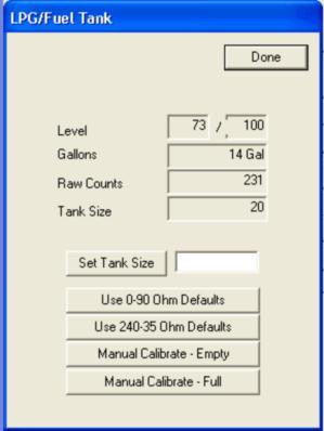
33 FEATURES TANK CALIBRATION SCREENS FEATURES TANK CALIBRATION SCREEN 1 ESSEX TANK CALIBRATION SCREEN 1 KING AIRE TANK CALIBRATION SCREEN 1 The first Tank Cal screen is accessed by pressing the Tank Calibration Button located on the Features Configuration Screen and entering the correct password or by pressing the Prev Button located on the second Tank Cal screen. This screen sets the tank capacities for the coach with the following settings: Fresh Tank Size (Essex = 105 Gal, King Aire = 140 Gal) Select value using the Up / Down Arrows Gray Tank Size (Essex = 65 Gal, King Aire = 80 Gal) Select value using the Up / Down Arrows Black Tank Size (Essex = 45 Gal, King Aire = 60 Gal) Select value using the Up / Down Arrows Page 31


34 FEATURES TANK CALIBRATION SCREEN 2 The second Tank Cal screen is accessed by pressing the Next Button located on the first Tank Cal screen. This screen is used to set the tank sensor Dry Calibration points. The Dry Calibration point should only be set with tank empty or the sensor removed and exposed to atmospheric pressure. This screen controls the following functions: Pressing the Fresh Dry Calibrate Button sets the Fresh Tank Sensor Dry-Point Pressing the Gray Dry Calibrate Button sets the Gray Tank Sensor Dry-Point Pressing the Black Dry Calibrate Button sets the Black Tank Sensor Dry-Point This screen allows you to confirm or cancel setting the tank sensor dry point for the selected tank. Page 32


35 FEATURES CLIMATE CONFIGURATION SCREENS FEATURES CLIMATE CONFIGURATION SCREEN 1-3 by pressing the Left Up Arrow located on the third Climate Setting screen. This screen allows you to change the following settings: Scheduling This feature allows you to set different HVAC set points depending on the time of day. Select value using the Up / Down Arrows Secondary Heat Mgmt This setting determines how the Oasis Heating System is controlled. Select value using the Up / Down Arrows The Password Access Screen is displayed to provide access to advanced system configuration screens. The advanced configuration screens contain control settings that should only be changed by qualified individuals The first Climate Setting screen is accessed by pressing the Climate Configuration Button located on the Features Configuration Screen or Scheduling This feature allows you to set different HVAC set points depending on the time of day. Select value using the Up / Down Arrows Sec. Heat Mgmt Set to Automatic This setting determines how the Oasis Heating System is controlled. Select value using the Up / Down Arrows Heat/Cool Lockout This setting determines if HVAC Heat and Cool commands can be issued at the same time in different zones. (EX: LvRm Heat & Kitch Cool) Select value using the Up / Down Arrows Dehumidifier Set to None This setting determines if a Dehumidification AC Unit is installed on the coach. This setting should be set to Installed only when a Dehumidification equipped A/C unit is installed on the coach. Select value using the Up / Down Arrows Page 33

36 FEATURES CLIMATE CONFIGURATION SCREEN 4 The fourth Climate Setting screen is accessed by pressing the Left Down Arrow on the first Climate Setting screen or by the Left Up Arrow on the fifth Climate Setting screen. This screen determines the Zone Labels that are displayed on the Climate control screens and has the following settings: Zone 1 Name Set to LvRm Zone 2 Name Set to Kitch Zone 3 Name Set to Bath Zone 4 Name Set to Bed FEATURES CLIMATE CONFIGURATION SCREEN 5 The fifth Climate Setting screen is accessed by pressing the Left Down Arrow on the third Climate Setting screen or by the Left Up Arrow on the sixth Climate Setting screen. This screen sets the Cool Source to the HVAC Zones. Cool Instance 1 Set to 1 Cool Instance 2 Set to 2 Cool Instance 3 Set to 0 Cool Instance 4 Set to 4 FEATURES CLIMATE CONFIGURATION SCREEN 6 The sixth Climate Setting screen is accessed by pressing the Left Down Arrow on the fourth Climate Setting screen or by the Left Up Arrow on the seventh Climate Setting screen. This screen sets the Heat Source to HVAC Zones. Heat Instance 1 Set to 1 Heat Instance 2 Set to 2 Heat Instance 3 Set to 166 Heat Instance 4 Set to 4 Page 34
37 FEATURES CLIMATE CONFIGURATION SCREEN 7 The seventh Climate Setting screen is accessed by pressing the Left Down Arrow on the fifth Climate Setting screen or by the Left Up Arrow on the eighth Climate Setting screen. This sets the Temperature Sensors to the HVAC Zones. Temp Instance 1 Set to 1 Temp Instance 2 Set to 2 Temp Instance 3 Set to 248 Temp Instance 4 Set to 4 FEATURES CLIMATE CONFIGURATION SCREEN 8 The eighth Climate Setting screen is accessed by pressing the Left Down Arrow on the sixth Climate Setting screen or by the Left Up Arrow on the ninth Climate Setting screen. This screen specifies the Oasis Zones to control from the HVAC Zone settings. Sec. Heat Instance 1 Set to 164 Sec. Heat Instance 2 Set to 0 Sec. Heat Instance 3 Set to 166 Sec. Heat Instance 4 Set to 167 FEATURES CLIMATE CONFIGURATION SCREEN 9 The ninth Climate Setting screen is accessed by pressing the Left Down Arrow on the eighth Climate Setting screen. This screen is used to set the Primary Heat Zone control. Primary Heat Instance 1 Set to 1 Primary Heat Instance 2 Set to 0 Primary Heat Instance 3 Set to 0 Primary Heat Instance 4 Set to 4 Page 35


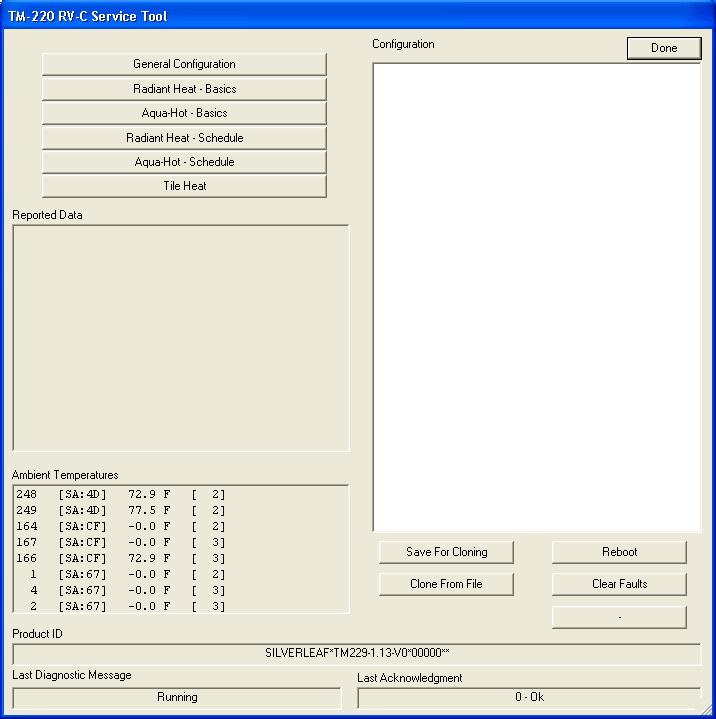
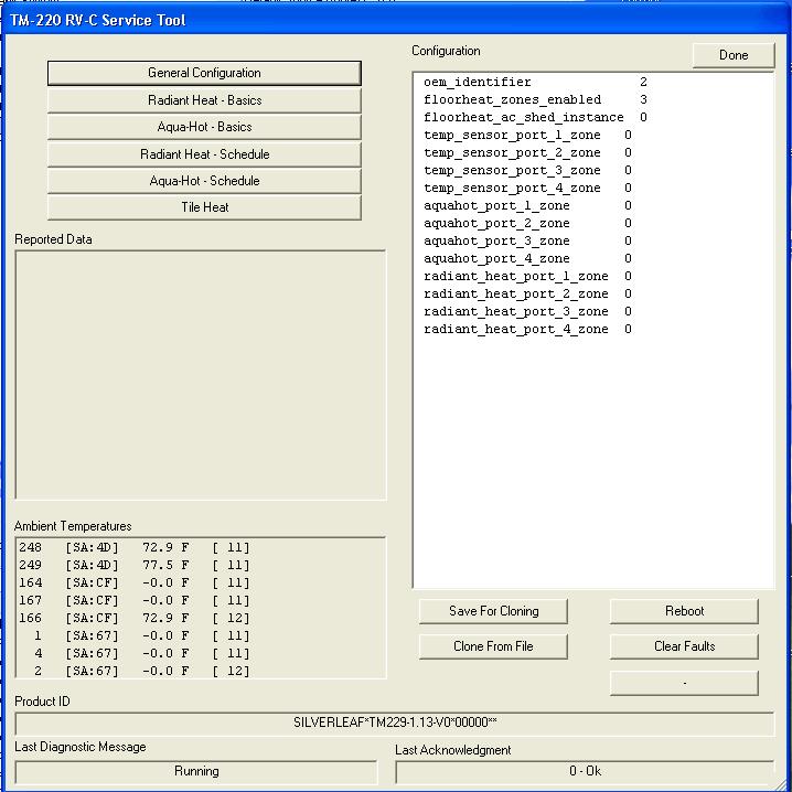
38 FEATURES TM102 CONFIGURATION SCREEN The TM102 Flags screen is accessed by pressing the TM102 Configuration Button located on the Features Configuration Screen. This screen displays the active system functions. FEATURES COMPONENT VERSIONS SCREEN The Component Versions screen is accessed by pressing the Components Versions Button located on the Features Configuration Screen. This screen displays all of the RV-C Modules and their firmware versions found on the system. Page 36
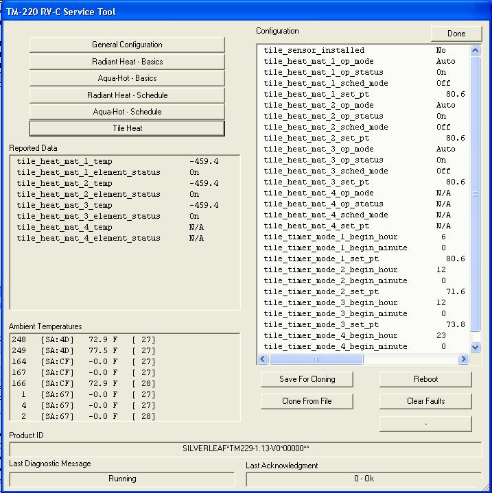
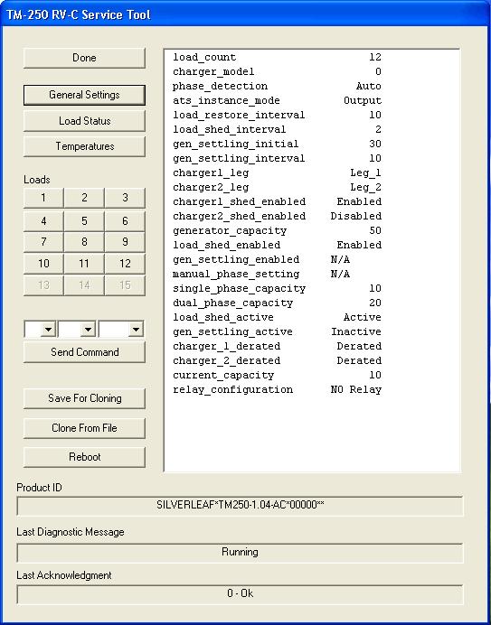
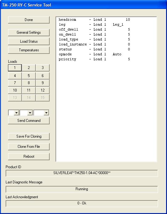
39 Newmar SilverLeaf Module Configuration Data & Screens 3 ACs Zones 1,2 &4 Zone Temp Display Source Primary Source 3 Heat Pumps Secndry Heat Source 3 Oasis HMS360 Monitor TM229 (TM220 Series) Tile Heat Function Setting Function Setting Block Heater Instance 1 OEM Identifer 2 Air Conditioner Model 1 Ambient Temperature Instance 249 TM250 Load Manager Zone 1 Cool Instance 1 Load1 Load Type 5 Zone 2 Cool Instance 2 Zone 3 Cool Instance 0 TM510 (Dometic) Zone 4 Cool Instance 4 Secondary Heat Mode 0 Zone 1 Heat Instance 1 Heat Pump Temp Limit 40 Zone 2 Heat Instance 2 Outside Air Temp Instance 249 Zone 3 Heat Instance 166 Secondary Heat Boost Level 5 Zone 4 Heat Instance 4 Zone 1 Instance 1 Zone 1 Temp Instance 1 Zone 1 Secondary Heat Instance 164 Zone 2 Temp Instance 2 Zone 1 Compressor Instance 2 Zone 3 Temp Instance 248 Zone 1 Fan Instance 3 Zone 4 Temp Instance 4 Zone 2 Instance 2 Zone 1 Furnace Instance 1 Zone 2 Secondary Heat Instance 165 Zone 2 Furnace Instance 2 Zone 2 Compressor Instance 4 Zone 3 Furnace Instance 0 Zone 2 Fan Instance 5 Zone 4 Furnace Instance 4 Zone 3 Instance 0 Zone 1 Sec Heat Instance 164 Zone 3 Secondary Heat Instance 0 Zone 2 Sec Heat Instance 0 Zone 3 Compressor Instance 0 Zone 3 Sec Heat Instance 166 Zone 3 Fan Instance 0 Zone 4 Sec Heat Instance 167 Zone 4 Instance 4 Zone 4 Secondary Heat Instance 167 Zone 4 Compressor Instance 6 Zone 4 Fan Instance 7 Page 37
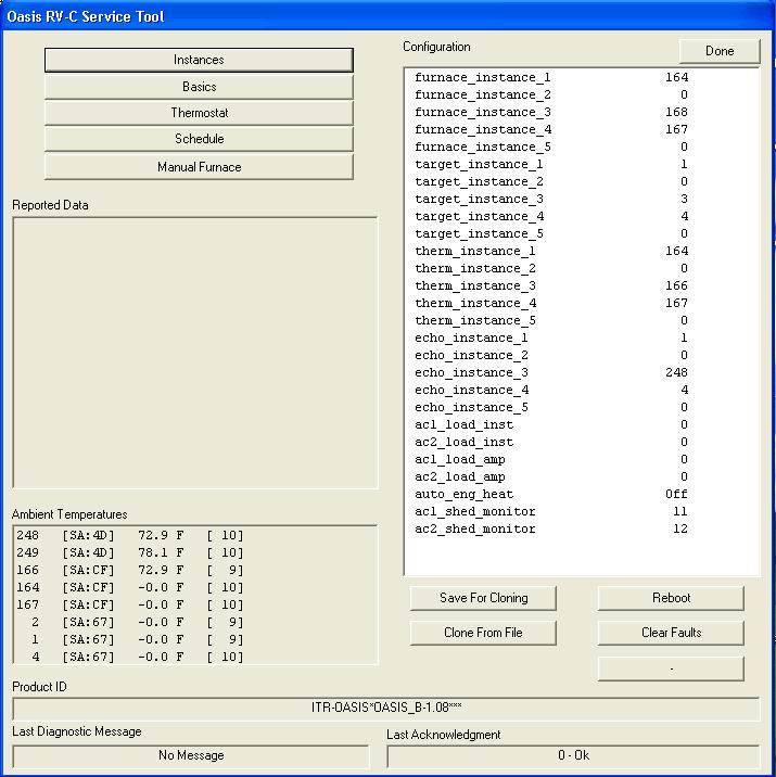
40 OA600 (Oasis) Function Setting Furnace Instance Furnace Instance 2 0 Furnace Instance Furnace Instance Furnace Instance 5 0 Target Instance 1 1 Target Instance 2 0 Target Instance 3 3 Target Instance 4 4 Target Instance 5 0 Thermostat Instance Thermostat Instance 2 0 Thermostat Instance Thermostat Instance Thermostat Instance 5 0 Echo Instance 1 1 Echo Instance 2 0 Echo Instance Echo Instance 4 4 Echo Instance 5 0 AC1 Load Instance 0 AC2 Load Instance 0 AC1 Load Amp 0 AC2 Load Amp 0 Auto Engine Heat 0 AC1 Shed Monitor 11 AC2 Shed Monitor 12 Page 38


41 Displays Module type associated with selection from LH window ALL ELECTRIC OPTION LP STANDARD Page 39

 LPG Tank Set to")
42 ALL ELECTRIC OPTION All Electric Option LPG Tank Set to Off LP STANDARD LP (Standard) LPG Tank Set to On Page 40


43 Page 41

44 Page 42

45 EXDP TANK CAPACITIES KGDB TANK CAPACITIES Page 43
46 Page 44
47 Page 45
48 Page 46
49 Page 47
50 Page 48
51 Temperature values reported from SilverLeaf Temp Sensors for respected instances. Page 49
52 Page 50

53 Page 51
54 Page 52

55 Status values reported from Dometic Network. Page 53

56 1 if Heat Pump Enabled 1 if Heat Pump Enabled 1 if Heat Pump Enabled NOTE: (1) The zone_x_ heat_installed configuration value that is displayed is Dometic System status only. It cannot be changed with the OmniScope Tool. The value displayed indicates the dip switch setting on the associated zone Dometic control board. (2) Zone 3 values are all zeros, This is because there are no HVAC devices that use this Dometic network zone. The only assigned Dometic zones are 1, 2 & 4, which correspond to the Living Room, Kitchen and Bedroom air conditioners. Page 54
57 Temperature values reported from Dometic Temp Sensors for respected zones. Page 55

58 Temperature values reported from all RV-C Network Temp Sensors by instance. Page 56
59 Page 57
60 Blank Page Page 58
61 Newmar SilverLeaf Control System Diagnostic and Repair Procedures RV-C Control System Introduction The SilverLeaf Control System is a RV-C (CAN bus) based multiplex networked control system that uses multiple specialized control nodes (modules) to monitor and control the various systems in the RV. The RV-C network, in its simplest form, consists of a trunk cable made up of a twisted pair cable with 120 Ohm terminating resistors at each end of the trunk run. The nodes are connected to the network via drop cables attached to the trunk cable at any convenient location along the trunk. The trunk and drop cables provide the RV-C network communications. In its basic form, the RV-C network does not provide power for the nodes over the network. The power to the nodes is supplied by separate dedicated wiring. The RV-C network scheme that Newmar employs for the SilverLeaf control system consists of multiple 4 conductor Trunk cable segments connected together by Drop Tees. The modules are connected to the network via Drop cables that plug directly into the tees. The Trunk segments are made up of a 2 wire twisted-pair communications cable along with separate 12 VDC power and ground wires bundled together into a single cable assembly. The Trunk cables are terminated with 4 pin mini-fit jr connectors on each end of the cable. The Drop Tees are either a single or multiple Drop Tee. The Tees have a mating mini-fit jr connector on each end with one or more drop mini-fit jr connectors along the adjacent edge. The beginning and end of the entire Trunk has a Terminating Resistor built into the last Drop Tee Board. The terminating resistors are required to assure proper communications across the network. The control nodes are interfaced to the network using Drop cables similar in construction to the Trunk cables. The standard drop cables have a 4 pin mini-fit jr connector for connection to the drop tees on one end with a 12 pin mini-fit jr connector for the node connection on the other end. Some of the drop cables also have additional wiring on the node end connector to accommodate other control interface functions. In this application the network provides both the communications and power to the nodes via the 4 pin connectors. Currently there are two networked nodes that do not receive their power over the network. The TM-102 Total Coach Manager and the TM-502 Magnum Master are both constantly powered from separate fuses located on the Power Relay Board mounted on the back bulkhead of the Shore Power Electrical Compartment. The Power Relay Board is supplied with constant 12 VDC house battery power via a minibreaker connected directly to the house battery bank. This circuit in not supplied from the Battery Disconnect power supply. All other nodes are powered over the network from a fuse located on the 12 VDC fuse panel mounted to the back bulkhead in the Shore Power Electrical Compartment. The network power is supplied from the Battery Disconnect power supply. Refer to Newmar RV-C Layout drawing for a detailed network layout. Page 59
Total Coach System. for Foretravel Users Manual. SilverLeaf Electronics, Inc Ferry St SW Albany, OR (888)
") Total Coach System for Foretravel Users Manual SilverLeaf Electronics, Inc. 2472 Ferry St SW Albany, OR 97322 (888) 741-0259 www.simply-smarter.com Overview The Total Coach System as installed by Foretravel
Total Coach System for Foretravel Users Manual SilverLeaf Electronics, Inc. 2472 Ferry St SW Albany, OR 97322 (888) 741-0259 www.simply-smarter.com Overview The Total Coach System as installed by Foretravel
Owner s Manual Revision 4.01 Option 1
 Owner s Manual Revision 4.01 Option 1 Special Version of the SW series Inverter / Charger for Motor Coach Applications Part # 2031-7 (Supplement to Normal Manual) Effective Date: April 17, 1996 Trace Engineering
Service Bulletin SB685. Date: 8/18/2017 TriPac EVOLUTION Communications Update Bulletin Location: TSA Info Central\Service Bulletins
 Service Bulletin SB685 Date: 8/18/2017 Subject: TriPac EVOLUTION Communications Update Bulletin Location: TSA Info Central\Service Bulletins Units: All TriPac EVOLUTION Summary: This bulletin updates and
METERING/DISPLAY MANUAL
 METERING/DISPLAY MANUAL 175W - 750W SINGLE PHASE Series LV EMERGENCY LIGHTING CENTRAL INVERTER Myers Power Products, Inc. 44 South Commerce Way, Bethlehem, PA 18017 1-800-526-5088 (610) 868-3500 Fax: (610)
Model HM-535 Power Supply Installation and Service Instructions
 Model HM-535 Power Supply Installation and Service Instructions 430-535 0104 2004 Heritage MedCall, Inc SENTRY INSTALLATION & SERVICE INSTRUCTIONS POWER SUPPLY UNIT Model HM-535 IMPORTANT SAFETY INSTRUCTIONS
BEP 600-ACSM AC SYSTEMS MONITOR. Installation and Operating Instructions. Page 1
 BEP 600-ACSM AC SYSTEMS MONITOR Installation and Operating Instructions Page 1 This page has been deliberately left blank Page 2 Table of Contents 1. BASICS 4 WARNING AND CAUTION 4 WARNING 4 CAUTION 4
COMFORT CONTROL CENTER SERVICE INSTRUCTIONS
 USA SERVICE OFFICE Dometic Corporation 2320 Industrial Parkway Elkhart, IN 46516 574-294-2511 CANADA Dometic Corporation 46 Zatonski, Unit 3 Brantford, ON N3T 5L8 CANADA 519-720-9578 For Service Center
Call Toll Free: Website:
 1 2 Introducing Road Commander Intellitec is launching a new product family, named Road Commander that will allow you to control your RV systems via a touch screen, control center, or smart phone, whether
Hardware definition of comm system:
 Filename = Magnum Networking Communications Protocol.XLS 7-May-03 Update 10-Oct-03 Update 23-May-05 add 0% charge rate and 250 VAC Dropout for ac disconnect for EMS support Update 28 March 2006 for new
Operation Guide CT100
 Operation Guide CT100 PG 1 The CT100 communicating Z-Wave thermostat operates via a high-quality, easy-to-use touch screen. To set or adjust your CT100, simply touch your finger firmly to the screen. The
Operation 6035 ENGLISH PROG MENU
 Operation 6035 PROG MENU ENGLISH Operation 6035 Program button Time of day Day Time Slot Current Room Temperature Target Temperature Menu button PROG MENU FAN AUTO ON COOL OFF HEAT Fan Switch Touch Screen
FX-2 Control Board ASY-360-XXX Setup and Configuration Guide
 FX-2 Control Board ASY-360-XXX Setup and Configuration Guide Micro Air Corporation Phone (609) 259-2636 124 Route 526. WWW.Microair.net Allentown NJ 08501 Fax (609) 259-6601 Table of Contents Introduction...
DC M2 OLED Meter Instructions PN 1830 / PN 1832 / PN 1833 / PN 1834
 DC M2 OLED Meter Instructions PN 1830 / PN 1832 / PN 1833 / PN 1834 Installation Checklist Check for components included Read Warning and Cautions Read QuickStart Installation Guide for mounting instructions
Quick Start Installation and User Manual
 1 Quick Start Installation and User Manual Contents 1. Overview 2. Technical Specifications 3. Installation Mounting Electrical Installation Clamp Installation Wiring Diagrams 4. Installation Settings
Operation Guide CT101
 Operation Guide CT101 PG 1 The CT101 communicating Z-Wave thermostat operates via a high-quality, easy-to-use touch screen. To set or adjust your CT101, simply touch your finger firmly to the screen. The
Temperature controller Ducted systems
 2 725 Temperature controller Ducted systems Standard model without zoning functions RRV851 Multifunctional controller used for central control of ducted HVAC systems in combination with a QAX850 master
Operation Guide CT32 ENGLISH
 Operation Guide CT32 The CT32 communicating thermostat operates via a high-quality, easy-to-use touch screen. To set or adjust your CT32, simply touch your finger firmly to the screen. The screen will
IO-INTERFACE. Procon. INSTALLATION MANUAL Version 1.01 MITSUBISHI ELECTRIC FOR INSTALLERS
 Procon IO-INTERFACE FOR INSTALLERS INSTALLATION MANUAL Version 1.01 For safe and correct use, please read this installation manual thoroughly before installing the PROCON IO-INTERFACE. MITSUBISHI ELECTRIC
V0STAT51P-2 Programmable Wired Controller
 PRODUCT SPECIFICATIONS VARIABLE REFRIGERANT FLOW SYSTEMS VRF V0STAT51P-2 Programmable Wired Controller Bulletin No. 210766 March 2016 Grouping - Controller can control up to 16 indoor units on the same
Trouble Shooting Leveling Control Box Electric Jacks. Touch Pad LED Probable Cause Solution
 Trouble Shooting Leveling Control Box 140-1224 Electric Jacks Copyright Power Gear Issued: January 2013 #82-L0524, Rev. OA Touch Pad LED Probable Cause Solution 1. On/Off LED will not light 2. Wait LED
FX-2 Control Board ASY-360-XXX Setup and Configuration Guide
 FX-2 Control Board ASY-360-XXX Setup and Configuration Guide Micro Air Corporation Phone (609) 259-2636 124 Route 526. WWW.Microair.net Allentown NJ 08501 Fax (609) 259-6601 Table of Contents Introduction...
Abstract. GLV User Manual 1
 GLV User Manual 1 Abstract This user manual is a high level document that explains all operational procedures and techniques needed to operate the GLV system in a safe and effective manner. Anyone operating
Technical Manual Nova: Cabinet Security Management System (CSMS)
") Technical Manual Nova: Cabinet Security Management System (CSMS) KP_nova_TM_160501_EN 1 Publication May, 2016, Keyprocessor BV Paasheuvelweg 20 1105BJ Amsterdam, The Netherlands www.keyprocessor.com/nova
Technical Manual Nova: Cabinet Security Management System (CSMS) KP_nova_TM_160501_EN 1 Publication May, 2016, Keyprocessor BV Paasheuvelweg 20 1105BJ Amsterdam, The Netherlands www.keyprocessor.com/nova
INSTALLATION INSTRUCTIONS MBPEFY Series Mixing Box for Mitsubishi PEFY Series Units. Before Starting Installation Warning. Installation Instructions
 Before Starting Installation Warning Shut power to unit prior to any work being done. Personal injury or death could result. Only qualified HVAC service personnel should install, troubleshoot, repair or
Sidewinder Pumps Inc. AC Timer/Controller
 Sidewinder Pumps Inc. AC Timer/Controller Page 1 of 12 Rev 032417 Table of Contents 1. Warnings-------------------------------------------------------------------------------------------------- 3 1.1.
BEP 600-DCSM DC SYSTEMS MONITOR. Installation and Operating Instructions. INST-600-DCSM-V1 Page 1
 BEP 600-DCSM DC SYSTEMS MONITOR Installation and Operating Instructions INST-600-DCSM-V1 Page 1 This page has been deliberately left blank INST-600-DCSM-V1 Page 2 Table of Contents 1. BASICS 4 Features
ALLEGRO 'OPEN ROAD' NETWORK DIAGRAM
 DRIVER ON 12V MTR OFF ON ENTRY STEP OFF 2013-2016 ALLEGRO 'OPEN ROAD' NETWORK DIAGRAM DCBR24-33 PANEL 1 2 3 4 5 6 CDC PANEL (no network connection) FRONT VIEW PARK PARK/ IGN IGN FUSED BATT 1 FUSED BATT
Viconics VT76x6W Water-source Heat Pump Controllers Engineering Guide Specification
 Viconics VT76x6W Water-source Heat Pump Controllers Engineering Guide Specification General The VT76xxW series is designed for single-stage and multi-stage control of water source heat pumps with dedicated
Torque Series LCD Remote Panel Installation/Operation Manual Model: TQ-DSP-12/24
 Torque Series LCD Remote Panel Installation/Operation Manual Model: TQ-DSP-12/24 Section Page Introduction 1 Materials Provided 1 I) Safety Instructions 1 A) Inverter Safety Instructions 1 B) Battery Safety
Supplementary operating instructions for your air curtain system Controller TMC 500
 Supplementary operating instructions for your air curtain system Controller TMC 500 (Translation of the original) Serial number: Year: Please quote this number when contacting customer service! Date 08.04.2016
FCU-4 FAN COIL CONTROLLER
 FCU-4 FAN COIL CONTROLLER BACnet Enabled Description The FCU-4 is designed to provide complete control of fan coil units. The FCU-4 incorporates all the inputs and outputs to ensure that this advanced
Owner s Manual. Digital Player Addendum. For Heat Siphon Swimming Pool Heat Pumps
 Made in Latrobe Since 1983 Pennsylvania U.S.A. Owner s Manual Digital Player Addendum For Heat Siphon Swimming Pool Heat Pumps Heating Only Models: Z250HP, Z375HP, Z575HP & Z700HP Z250HP50, Z375HP50, Z575HP50
SERIES CMT CARBON MONOXIDE GAS TRANSMITTER
 SERIES CMT CARBON MONOXIDE GAS TRANSMITTER INSTALLATION OPERATION AND MAINTENANCE MANUAL DWYER INTRUMENTS, INC. PO BOX 373, MICHIGAN CITY, IN. 46360 USA PHONE: 800-872-9141 FAX: 219-872-9057 Web: www.dwyer-inst.com
Pr ec is io n Cir c uit s I n c
 Pr ec is io n Cir c uit s I n c Introduction Summary Strengths Highlights Operations People Products Power Control System Mission Statement Summary Precision Circuits Inc is a privately owned corporation,
Master room unit for RRV controllers
 2 722 Master room unit for RRV controllers 2 wire bus connection QAX850 Multifunctional, digital room unit for installer and end-user interface with RRV controllers. Use Use Application Room unit in combination
MiG2 CONTROLLERS. 2 & 4 Stage General Purpose Controllers, with Air-conditioning Facilities
 MiG2 CONTROLLERS 2 & 4 Stage General Purpose Controllers, with Air-conditioning Facilities The MiG2 controllers incorporate: 2 Inputs (Configurable as Resistive, 0 10V, 0 20mA or 4 20mA) 2 or 4 Relay Outputs
Please take serious note of the following warnings:
 TPDIN-SC48-20 MPPT Solar Controller with Passive PoE Switch Wireless Base Stations and Client Devices Surveillance Cameras Remote Control Remote Lighting Off Grid Electronics Congratulations! on your purchase
SC2000 MOTOR PROTECTION ELECTRONICS, INC. INSTRUCTION MANUAL. (407) Phone: Website:
 Phone: Website:") SC2000 INSTRUCTION MANUAL MOTOR PROTECTION ELECTRONICS, INC. 2464 Vulcan Road Apopka, Florida 32703 Phone: Website: (407) 299-3825 www.mpelectronics.com Operating Program Revision: 12 Revision Date: 8-27-14
SC2000 INSTRUCTION MANUAL MOTOR PROTECTION ELECTRONICS, INC. 2464 Vulcan Road Apopka, Florida 32703 Phone: Website: (407) 299-3825 www.mpelectronics.com Operating Program Revision: 12 Revision Date: 8-27-14
OPERATION INSTRUCTIONS
 2018 Lennox Industries Inc. Dallas, Texas, USA OPERATION INSTRUCTIONS V0STAT52 Wireless Indoor Unit Controller CONTROLS 507459-04 05/2018 This manual must be left with the owner for future reference. IMPORTANT
EnCell Battery Cell Monitor
 EnCell Battery Cell Monitor Instruction Manual Model RCM15S12 NERC Compliant YO R U H T PA TO Z O R E W O D N M I T E enchargepowersystems.com sales@enchargepowersystems.com (888) 407.5040 Contents 1 Warnings,
Model: Available in : Sapphire Black and Glacier White
 Model: Available in : Sapphire Black and Glacier White 1 Table of Contents Product Image 1 Locking/Unlocking the SmartStat 20 Table of Contents 2 Standby/Away Mode 21 What is a Programmable Room Thermostat?
NCSP3. Installation and Operation Manual RV CONTROL AND MONITORING SYSTEM. Patent # (D776,068) Patent # (D762,644) Patent # US 9,679,735
 Patent # (D762,644) Patent # US 9,679,735") RV CONTROL AND MONITORING SYSTEM Installation and Operation Manual Patent # (D776,068) Patent # (D762,644) Patent # US 9,679,735 Important Safety Information Read the in-command Manual, and these warnings
RV CONTROL AND MONITORING SYSTEM Installation and Operation Manual Patent # (D776,068) Patent # (D762,644) Patent # US 9,679,735 Important Safety Information Read the in-command Manual, and these warnings
Contents 1 Warnings, Cautions, and Notes Description Features... 1
 EnCell Contents 1 Warnings, Cautions, and Notes... 1 2 Description... 1 3 Features... 1 3.1 STANDARD FEATURES... 1 3.2 FRONT PANEL FEATURES... 2 3.2.1 Display... 2 3.2.2 OK LED... 2 3.2.3 FAULT LED...
FX 2 Instruction Manual
 FX 2 Instruction Manual Climma Compact Version Annapolis MD USA 301 352 6962 info@veco-na.com Introduction: The FX2-DX digital controller operates onboard air conditioning equipment to provide room temperature
I2:34 MODEL TSTATBBP2W01 PROGRAMMABLE DIGITAL THERMOSTAT. Heat only, or Cool only. Meets California Title 24 Residential USERS INFORMATION MANUAL
 USERS INFORMATION MANUAL Heating & Cooling Systems MODEL TSTATBBP2W01 PROGRAMMABLE DIGITAL THERMOSTAT NOTE TO INSTALLER: This manual must be left with the equipment user. I2:34 72 72 Heat only, or Cool
ME3 Mobile Cabinet Three Phase Frequency Converter, Operation and Maintenence.
 29-30 Brunel Road, Churchfields Industrial Estate, St. Leonards-on-Sea East Sussex. TN38 9RT. United Kingdom Sales & Service : 01424 853 013 All Other Departments : 01424 853 464 Fax : 01424 852 268 magnuspower.sales@akersolutions.com
SS2200 Remote Controller
 SS2200 Remote Controller General Purpose, DC Voltage General The SS2200 Remote Controller is a microprocessor-based programmable controller specifically designed to control single line and dual line centralized
Standard Options. Model 4100 Position Indicating Meter. Three Phase Motor Control. Positran Transmitter
 Standard Options Model 4100 Position Indicating Meter A percent-of-full-travel meter is supplied with a trim potentiometer resistor, terminal block and connectors. A potentiometer is required in the actuator
User Manual. Solar Inverter for Water Pump
 User Manual Solar Inverter for Water Pump SP Revival Series Version: 1.2 Table Of Contents ABOUT THIS MANUAL... 1 Purpose... 1 Scope... 1 SAFETY INSTRUCTIONS... 1 Inspection... 1 Installation... 1 Operation...
CRAGG RAILCHARGER Instruction Manual for 10DTC-12V 20DTC-12V 30DTC-24V 40DTC-12V 60DTC-12V
 CRAGG RAILCHARGER for 10DTC-12V 20DTC-12V 30DTC-24V 40DTC-12V 60DTC-12V Contents 1 Warnings, Cautions, and Notes... 1 2 Description... 2 3 Features... 2 3.1 STANDARD FEATURES... 2 3.2 CHARGER REGULATION...
Series F75 Fail-Safe Module Installation, Operation and Maintenance Instructions
 WCAIM2029 (Part 16022) Series F75 Fail-Safe Module Installation, Operation and Maintenance Instructions CAUTION: Flowserve recommends that all products that must be stored prior to installation be stored
Manual. NanoTron Dual Timer. Installation Maintenance Repair Manual
 Manual NanoTron Dual Timer Installation Maintenance Repair Manual Advantage Controls P.O. Box 1472 Muskogee, OK 74402 Phone: 800-743-7431 Fax: 888-686-6212 www.advantagecontrols.com email: support@advantagecontrols.com
Operation Manual. Concorde 600 Power Supply. *This instrument is intended for laboratory use only.
 Concorde 600 Power Supply Operation Manual Cat.no. R10-1001011 *This instrument is intended for laboratory use only http://www.recenttec.com E-mail : support@recenttec.com Version 1.1 Packing List x 1
EPS Power Supply
 EPS - 600 Power Supply Installation and Operation Manual Version 1.0 *This instrument is intended for laboratory use only Index A. Important Notice ----------------------------------------------------------------
Model: Available in : Sapphire Black and Glacier White
 1 Model: Available in : Sapphire Black and Glacier White 1 Table of Contents Product Image 1 Locking/Unlocking the SmartStat 20 23 Table of Contents 2 Standby/Away Mode Mode 21 24 What is a Programmable
Generac/Guardian Residential Standby Generators
 Generac/Guardian Residential Standby Generators Procedure to Enable 2-Wire Remote Start Document Number: BGS-GRC-RS-1 Date: 15 Mar 2010 Revision: F 603.787.2317 info@begreensolar.com Page 1 Revision Original
FX2-CHILLER. Digital Control. Operations Manual
 FX2-CHILLER Digital Control Operations Manual Micro Air Corporation Phone (609) 259-2636 124 Route 526 www.microair.net Allentown NJ 08501 Fax (609) 259-6601 Introduction: The FX2-CHILLER digital control
Innovative Electronics for a Changing World. Charge Smart R1 MPPT 12V/24V Auto detect Mains and Solar Battery charger with Remote Network Monitoring
 Innovative Electronics for a Changing World Charge Smart R1 MPPT 12V/24V Auto detect Mains and Solar Battery charger with Remote Network Monitoring INDEX 1. SYSTEM DESCRIPTION 2. SYSTEM WIRING 3. SYSTEM
TC-9102 Series Surface Mount Temperature Controllers
 TC-9102 Series Surface Mount Temperature Controllers General Description & Applications The TC-9102 Series Temperature Controller offers a versatile solution for a wide variety of applications that may
SOLARIMMERSION IV Advanced Installation Manual v1.9
 SOLARIMMERSION IV Advanced Installation Manual v1.9 1 Contents 1. Overview 2. Technical Specifications 3. Installation Mounting Electrical Installation Clamp Installation Wiring Diagrams 4. Installation
AirTest Model CN9000 Series Sensor Controller
 AirTest Model CN9000 Series Sensor Controller AirTest Model CN9000 Series Sensor Controller THEORY OF OPERATION A basic CN9000 configuration consists of Input/Process/Display combination modules, a 3 relay
IntesisBox. v.0.1. User Manual Issue Date: 12/2017 r1.3 EN
 IntesisBox HS-RC-MBS-1 v.0.1 Modbus RTU (EIA-485) Interface for Hisense air conditioners. Compatible with commercial line of air conditioners commercialized by Hisense. User Manual Issue Date: 12/2017
M2 OLED Temperature Monitor Instructions PN 1841
 M2 OLED Temperature Monitor Instructions PN 1841 Installation Checklist Check for components included Read Warning and Cautions Read page 3 for mounting instructions Read System Overview, Mounting Considerations,
Starzone 4000 Master Control Panel Figure 2.1 Master Control Panel
 Starzone 4000 Master Control Panel Figure 2.1 Master Control Panel The heart of the Starzone 4000 system is the Starzone Master controller (SZM-4000). Each AHU that is to be zoned will have its own SZM-4000
Installation and Operation Manual SPC1
 Installation and Operation Manual SPC1 BIA-SPC1 rev 5 Page 1 TABLE OF CONTENTS Page QUICK GUIDE DRAINAGE PUMP FLOATS CONNECTED TO PANEL 4-5 QUICK GUIDE DRAINAGE PUMP FLOAT CONNECTED TO PUMP 6-7 QUICK GUIDE
USER S MANUAL. DAS-G01 The Power of Tomorrow
 USER S MANUAL DAS-G01 The Power of Tomorrow Richmond Heights 2018 0 USER S MANUAL DAS-G01 The Power of Tomorrow Richmond Heights 2018 Page 1 USER'S MANUAL TABLE OF CONTENTS Page # 1.0 GENERAL INFORMATION...
Dryer. M720 Programming and Operation Manual. July 15, 2015 Revision 1.51
 Dryer M720 Programming and Operation Manual July 15, 2015 Revision 1.51 Contents 1 Important Safety Information 1 1.1 FOR YOUR SAFETY - CAUTION!............................. 1 2 Control Overview 2 2.1
WARNING!!!!!!!!! IMPORTANT INFORMATION: READ BEFORE INSTALLATION!
 V_Net Relay Module Installation Instructions: Part Number: 230-VM-RELAY WARNING!!!!!!!!! IMPORTANT INFORMATION: READ BEFORE INSTALLATION! The relay outputs of the 230-VM-RELAY module may turn on when not
Communicative controller for VAV systems
 FCR015 Communicative controller for VAV systems Summary FCR015 is a communicative controller for heating and cooling panels and a VAV (variable air volume) damper. It measures temperature and CO 2 concentration
Central Controller Operation & Installation Manual
 Central Controller Operation & Installation Manual YCZ-A004 CONTENT Function introduction of central controller... 1 Part info for central controller... 2 Page & Key Explanation... 4 Address Setting When
NETRONICS HS3500 CONTROLLER
 NETRONICS HS3500 CONTROLLER CUSTOMER NAME CONTROLLER SERIAL # CONTROLLER PART # PERSONALITY SWITCH SETTINGS BULLET PRESS CONFIGURATION DELIVERY DATE Contact the factory for help setting up your application.
Basic User and Installation Manual
 HERON ELECTRIC COMPANY LTD Basic User and Installation Manual Mi-4 Mi-8 Mi-12 Mi-16 Mi-144 Multi -Wire Controller Doc ref. Mi Multi Wire Basic November 2008 TABLE OF CONTENTS 1. About This Controller...
OPERATING INSTRUCTIONS 7 SERIES STATIC GENERATORS
 OPERATING INSTRUCTIONS 7 SERIES STATIC GENERATORS GB Contents Page 1 Introduction 4 2 Safety 5 3 Use 6 4 Checking on Delivered Equipment 6 5 General Specification and Dimensions 7 6 Positioning 10 7 Operating
Zone Manager INSTALLATION MANUAL 40KMC KMQ QNC QNQ
 40KMC------301 40KMQ------301 40QNC------3 40QNQ------3 INSTALLATION MANUAL Installation manual This control system only operates with indoor units of the following models: 40KMC------301 and 40KMQ------301
PduSetup User Manual. Professional Electronics for Automotive and Motorsport
 Professional Electronics for Automotive and Motorsport 6 Repton Close Basildon Essex SS13 1LE United Kingdom +44 (0) 1268 904124 info@liferacing.com www.liferacing.com PduSetup User Manual Document revision:
NCSP3. Installation and Operation Manual RV CONTROL AND MONITORING SYSTEM. Patent # (D776,068) Patent # (D762,644) Patent # US 9,679,735
 Patent # (D762,644) Patent # US 9,679,735") RV CONTROL AND MONITORING SYSTEM Installation and Operation Manual Patent # (D776,068) Patent # (D762,644) Patent # US 9,679,735 Important Safety Information Read the in-command Manual, and these warnings
RV CONTROL AND MONITORING SYSTEM Installation and Operation Manual Patent # (D776,068) Patent # (D762,644) Patent # US 9,679,735 Important Safety Information Read the in-command Manual, and these warnings
BIC 100 BERMAD Irrigation Control System
 BIC 100 BERMAD Irrigation Control System BIC 100 PROGRAMA 1234567 1 2 1 2 13:47 H:M MV M Operation Manual BERMAD Water Control Solutions Contents Page 1. General Description 03 2. Normal Mode Defining
DPC Warning. ! Do not pull the cable. Water Pump Digital Pressure Controller Installation and Operation Manual.
 11.Warning www.evak-pumps.com Assemble tool! Do not pull the cable! Do not poke the port! WARNING Wire conductors must not be exposed to avoid any shortage from the conductor end. DPC-10 Water Pump Digital
UC102 basic version with display and knob UC102BL version with display, knob and backlight UC102DK version without knob and display
 UC102 Communicative heating controller Summary UC102 is a communicative room heating controller with two inputs and one PWM output for control of a radiator or electrical heater. It can work autonomously,
Instruction Sheet Board Style Low Water Cutoff
 Instruction Sheet Board Style Low Water Cutoff 102-305 SUPERSEDES: REVISION E DATED December 12, 2007 #5401173-REV F PLANT ID 001-3902 US Patents 6,904,800, 7,243,540, and 7,317,993 Other Patents Pending
RVL470. Heating controller. G2522en. Installation Instructions. 1 Installation. 2 Commissioning Wall mounting DIN rail mounting
 G2522en Heating controller Installation Instructions RVL470 1 Installation 1.1 Place of installation In a dry room, e.g. the boiler room Mounting choices: In a control panel (on the inner wall or on a
Semi flush-mounted room temperature controllers with LCD
 s 3 077 RDD310 RDE410 Semi flush-mounted room temperature controllers with LCD For heating systems RDD310 RDE410 RDD310 and RDE410 features: Operating voltage AC 230 V 2-position control with On / Off
Instruction Manual CTC-1
 Troubleshooting & Specs CTC-1 Amps / Volts requirements Min / Max operating temperature Min / Max operating Humidity Temperature Measurement range Temperature Accuracy CO2 sensor type CO2 Measurement range
Owner s Manual RBC-AX32U(W)-E RBC-AX32U(WS)-E AIR CONDITIONER (SPLIT TYPE) Wireless remote controller kit. Model name: English.
-E RBC-AX32U(WS)-E AIR CONDITIONER (SPLIT TYPE) Wireless remote controller kit. Model name: English.") AIR CDITIER (SPLIT TYPE) Owner s Manual Wireless remote controller kit Model name: RBC-AX3U(W)-E RBC-AX3U(WS)-E Generic model name RBC-AX3U(W)-E Wireless remote controller model name WH-LSE Signal receiving
AIR CDITIER (SPLIT TYPE) Owner s Manual Wireless remote controller kit Model name: RBC-AX3U(W)-E RBC-AX3U(WS)-E Generic model name RBC-AX3U(W)-E Wireless remote controller model name WH-LSE Signal receiving
INSTALLATION MANUAL for the Application ihc-mirf
 INSTALLATION MANUAL for the Application ihc-mirf Contents Introduction 3 Installing the application on a mobile phone 3 Settings 4 Control 12 Introduction The applications ihc-mirf (for mobile phones with
JRVCS2 RV CONTROL AND MONITORING SYSTEM
 JRVCS2 RV CONTROL AND MONITORING SYSTEM Installation and Operation Manual Patent # (D776,068) Patent # (D762,644) Patent # (9,679,635) Important Safety Information Read the in-command Manual, and these
SMM501/501-H (Surveillance Mode Module) Ford Police Interceptors (Sedan and SUV)
 Ford Police Interceptors (Sedan and SUV)") An ISO 9001:2008 Registered Company SMM501/501-H (Surveillance Mode Module) 2013-2014 Ford Police Interceptors (Sedan and SUV) Introduction The SMM501/501-H is intended for 2013 and 2014 Ford Police Interceptors
An ISO 9001:2008 Registered Company SMM501/501-H (Surveillance Mode Module) 2013-2014 Ford Police Interceptors (Sedan and SUV) Introduction The SMM501/501-H is intended for 2013 and 2014 Ford Police Interceptors
MicroTech III Applied Terminal Systems BACnet MS/TP Communication Module
 Installation and Maintenance Manual IM 928-2 Group: Controls Part Number: 669207702 Date: March 2011 Supersedes: IM 928-1 MicroTech III Applied Terminal Systems BACnet MS/TP Communication Module NOTICE
M1000 INTELLIGENT ZONE CONTROL SYSTEM
 HARDWARE GUIDE DIMENSIONS & SPECIFICATIONS REV. 5.2 M1000 INTELLIGENT ZONE CONTROL SYSTEM ROOFTOP CONTROLLER 2 Table of Contents GENERAL INFORMATION... 3 PL-M1000 Rooftop Controller...3 Description...3
Microprocessor based Temperature / CO2 Controller c/w 365 Day Time Switch & Modbus Communication.
 HTC-DIGITAL-LCD Microprocessor based Temperature / CO2 Controller c/w 365 Day Time Switch & Modbus Communication. Features Use Australian Made and designed LCD 2 X 16 Character Backlit Display Five Programmable
FOR SERVICE TECHNICIAN S USE ONLY
 Tech Sheet Do not discard DANGER WARNING Electrical Shock Hazard Only authorized technicians should perform diagnostic voltage measurements. After performing voltage measurements, disconnect power before
WSHP-IOP-2 May Installation, Operation, and Programming. Tracer ZN510 Controller
 WSHP-IOP-2 May 1998 Installation, Operation, and Programming Tracer ZN510 Controller Literature History The Trane Company has a policy of continuous product improvement and it reserves the right to change
Kodiak Mobile INTELLIGENT DOCKING STATION USERS MANUAL PART NUMBER: PANASONIC CF53 TOUGHBOOK COMPATIBLE AN ISO 9001:2008 CERTIFIED COMPANY
 CUSTOMER SERVICE If you have any questions or require additional information please contact Customer Service at 877-455-6886, Monday though Friday, 8:00am - 5:00pm CST. TECHNICAL SUPPORT Kodiak Mobile
Innovative Electronics for a Changing World. NPM-R10 Remote Network Power Monitor. With optional relay board and GSM module INDEX
 Innovative Electronics for a Changing World NPM-R10 Remote Network Power Monitor With optional relay board and GSM module INDEX 1. SYSTEM DESCRIPTION 2. BOARD CONNECTIONS terminals and indicators 3. CONNECTION
ES-362U PRESETTABLE MASTER TIMER
 142 SIERRA ST., EL SEGUNDO, CA 90245 USA (310)322-2136 FAX (310)322-8127 www.ese-web.com ES-362U PRESETTABLE MASTER TIMER OPERATION AND MAINTENANCE MANUAL The ES-362U is a four digit, presettable 100 minute
Temperature control unit
 Temperature control unit 5739 18/19 Installation manual Part. U3582A - 12/08-01 PC Contents 1 - Introduction 5 1.1 - Warnings and tips 5 1.2 - Contents of package 5 2 - Description of the Control unit
UNT1100 Series. Binary Output Jumpers AO2 AO1 AO3 AO4 AOCM AOCM AOCM AOCM AO1. AI Switches Job Information N2 Address. Ref N2+ N2- ADDR 0 = ALL OPEN
 1 2 8 4 AI6 R R Installation Bulletin UNT1100 Issue Date 0309 UNT1100 Series Introduction The Unitary (UNT) controller (UNT1100 Series) is a digital controller with applications for air handling units,
REMOTE METER. Model: MT50 INSTRUCTION MANUAL
 REMOTE METER Model: MT50 INSTRUCTION MANUAL For use with solar charge controllers PU series, LS series, VS series, PTR series, Tracer MPPT series and other compatible controllers Remote Meter MT50 Please
FCU-4 FAN COIL CONTROLLER
 FCU-4 FAN COIL CONTROLLER BACnet Enabled Description The FCU-4 is designed to provide complete control of fan coil units. The FCU-4 incorporates all the inputs and outputs to ensure that this advanced
Trend-1 Vibration Data Logger. User Manual
 Trend-1 Vibration Data Logger User Manual Copyright College of Engineering-University of Basrah 2013 1 1. General Specifications 1.1 Features Thank you for being interested in purchasing Trend-1 Vibration