UNIT-V OPTICAL NETWORKS
|
|
|
- Tabitha Robinson
- 6 years ago
- Views:
Transcription
1 UNIT-V OPTICAL NETWORKS Point to point lines: Point to point fiber optic lines are the simplest transmission line. This type of link places the least demand on optical fiber technology and thus sets the basis for examine more complex system architecture. Fig: Simple point to point link The repeaters may be opto electronic (or) optical repeaters. In this system, the repeater spacing is a major design factor spacing between repeater increases, it reduces the system cost spacing between transmitters receiver increases, it will also increases system cost.(ie transmission distance and increases) If L increases then bit rate reduces because of dispersion thus, product of B(bit rate) and transmission distance(l) is a measure of system performance and its depends on operating wavelength Operating wavelength BL product 0.854m 1Gb/s-Kn 1.34µm 1 Tb/s-Km 1.55µm 100Tb/s-km To analyze the point to point link. One should know the system requirements such as the maximum transmission distance, required data rate and allowed bit error rate (BER).
2 To satisfy these requirements the system should be designed based on the components available and their characteristics. 1. Multimode (or) single mode fiber (transmission media) (a)core radius (b) fiber repactive index profile (c) bandwidth (or) dispession (d) fiber attenuation (e) numerical aperture 2. Optical sources (LED or laser diode) (a) Emission wavelength (b) output power (c) spectral line width (d) radiation pattern (e) radiating area (f) no. of emitted modes (g) stability and life time. 3. Light detectors (PIN (or) APD) (a) Responsivity (b) efficiency (c) operating wavelength (d) speed (e) sensitivity (f)noise figure System considerations: a. Operating wavelength selection: First generation optical wavelength are in the range of 0.8µm to 0.9µm. Here the transmission less is maximum and dispersion is also maximum. Today we choose the wavelength around 1.3µm to 1.55µm. Here the attenuation and dispersion are very small in silica fibers are used for long distance transmission. b. System performance: System performance is decided by three major blocks (or) the optical fiber transmission. They are transmitter, optical fiber links and receiver. The designer should choose proper light source, proper optical fiber and proper photo detector to get high bit rate and high S/N ratio. Regarding optical fiber, the single mode step index fiber is the proper choice. Even in that to reduce dispersion proper choice of the refractive index profile is necessary. These single mode step index fibers are preferable. Regarding optical sources, single mode laser diodes are suitable for single mode stop index fibers. For multi mode fibers, heterojunction LEDs chosen based on economy. Regarding optical receivers, the P-i-n photodiodes and avalanche photodiodes are preperable. Here also they should be quantum noise limited.
3 The maximum transmission distance is limited by the net less of fiber cable such that L=10/α log10(pt/pr) α=not loss (in db/1cm) Pt=average power from transmitter Pr=average power detected at receiver =NphvB Np=minimum no. of photons/bit required Hv=energy of photon B=bit rate Link Power Budget: The main aim of power budget is to have enough power at the receiver so as to maintain reliable performance during the life time of the entire fiber optic system. The minimum power required at the receiver is the receiver sensitivity Pmin. The average power launched at the transmitter is Ptr. Generally less can be calculated by Loss(dB)=10log (Pout/pin) Where Pin and pout =optical power emerging in and out of the element Let Ptr=transmit power Pmin=minimum power required at the receiver(decides receiver sensitivity) Ploss=Total power loss produced by the fiber optic channel Psm=system margin Fig: optical power loss model for point to point links
4 System margin is the link power margin which is normally added with the total power less in the analysis of power budget where αfl=fiber attenuation (db/km) Lc =connector loss. lsp=splicing loss Total power loss PT=Ptr-Pmin Subs (2) in (3) Therefore, PT= αfl+ lc+lsp +system margin (Psm ) for simplicity add connector loss and splicing loss ie lc=lsp Usually system margin is 6 to 8 db Rise budget: In linear system, the rise time is defined as the time during which the response increases From 10% to 90% of the final output value when the input is changed abruptly in a stop wise manner. τr = rise time τf=fall time Rise time budget analysis is a method for determining the dispersion limitation of an
5 optical fiber link. The rise time of the system is given by ti= Rise time of each component in the system There are four basis element that limit the system spped of optical communication system. 1. Transmitter rise time 2. Receiver rise time 3. Material dispession rise time 4. Modal dispession rise time 1. Transmission rise time (ttx): It depends on light source, drive circuit of light source. It is the calculated value and it is specified optical fiber data sheet. 2. Receiver rise time (trx): It depends on photodetector response and receiver front and response. Receiver front and response depends on first order low pass filter in the receiver having step response and it is given by u(t)=step frequency Brx=3dB Bandwidth of receiver The rise time of the receiver is defined as the time interval between g(t)=0.1 to g(t)=0.9. This is known as 10 to 90% rise time. It is generally given by Trx=350/ Brx (or) 350/B B= Brx 3. Material dispession rise time: σλ=half of spectral width of the source D=dispession parameter (Its value change from fiber
6 to fiber) L=Length of the optical fiber 4. Modal dispession rise time: The relationship between B.W and rise time of the fiber is given by t modal =0.44/BM(L) BM(L)=Bandwidth BM in a link length L can be expressed by approximate emphrical relation as, BM(L)=Bo/Lq Where Bo=B.W of 1Km length of fiber cable Q=empirically fit parameter Q=1 indicates steady state modal equilibrium is not reached Q=0.5 indicates steady state modal equilibrium is reached t modal =0.44/ Bo/L q = 0.44L q /B o Total rise time of optical system is given by Where all time t sys is in nano seconds SONET: (Synchronous Optical Network) SONET is the set of standards developed by Bell core and then adopted by 170-7(cc 177) as an international standard designated Synchronous Digital Hierarchy (SDH). SONET specifies the rates, formats and parameters of all physical transmission media. Even though SONET is called an optical network, it can support traditional electrical transmission. The electrical signal in SONET are called Synchronous Transport Signal(STS).STS level 1,designated as STS-1 transmit at Mbits/sec. All other levels are multiples of STS-1 as shown in the following table.
7 Electrical signal Optical signal Bit rate STS-1 OC STS-3 OC STS-9 OC STS-12 OC STS-18 OC STS-24 OC STS-48 OC Higher bit rate signals, starting with STS-9 are not defined as electrical standards and they never actually transmitted in electrical form Structure of STS-1 format: An STS frame consists of 9 rows and 90 columns of 8-bit bytes for a total of 810 bytes (6480 bits).the duration of each frame is 125µs. Path overhead: It provides end to end communication99 bytes length column wise only).it is inserted to user data or payload by the end transmitter. It remains attached until the data reaches the end receiver. It monitors end equipment, status, signal labeling and a user channel. Transport overhead: It provides communication between STS-N multiplexer and adjacent nodes such as regenerators (ie,) it carries network management function.
8 CONVERSION OF DIGITAL SIGNAL TO OPTICAL SIGNAL (OC): Elements of SONET network: SONET uses terminal multiplexers(tm),add-drop multiplexer (ADM),digital cross connects(dcs) and generators. Terminal multiplexer: Low speed links connected to SONET through terminal multiplexers. It is also called line terminating equipment(lte).if a TM is connected to digital cross connect, we have a point to point link. Add drop multiplexer: It is used to pick out one or more low speed streams from a high speed streams and add one or more low speed streams to high speed streams. Digital cross connect: It is used to manage all the transmission facilities in the central office. It is actually a digital switch. It also monitors network performance and do multiplexing. Regenerators: It is used to boost a signal for long distance transmission
9 Figure : Elements of a SONET infrastructure Elements of SONET infra structure: SONET layers: 1.Physical layer: It is responsible for the transmission of bits over physical media. The SONET standard specifies such physical media as optical fibre and light sources with operating wavelengths that depends on the bit rates and distance for which the SONET network id designed. SONET systems are sub-divided into three networks: a. Short reach networks (SR) b. Intermediate reach networks (IR) c. Long reach networks (LR)
10 For short reach network, SONET recommended 1310nm operating wavelength LED and multimode fiber. For long reach network, SONET recommended 1550nm operating wavelength DFB laser diode and single mode fiber. Physical layer is needed as each node. 2. Section layer: It is responsible for sending data to the physical layer. It interface with the physical layer by adding appropriate bytes to the frame overhead. It also provides error monitoring and control. It regenerates the signal and protect the multiplexing and switching operations. Section layer is needed at each regenerator. 3. Line layer: It is responsible for multiplexing many path layer connections onto a single link between adjacent nodes. This layer also provides most of the operating, administrative management and provisioning (OAM& P) functions, including network protections. A line layer needed at ADMS and TMS. 4. Path layer: It is an end to end layer. It is responsible for connections between a source and destination. It accepts data from line layer, adds routing and error control information. It also monitors and tracks the status of connection. A path layer is needed at each SONET terminal multiplexer. Passive Optical Network (PON): PON use some form of passive components such as optical star coupler or static wavelength router as the remote node. Simple PON architecture uses a separate fiber pair from the CO to each ONU. The main
11 Problem with this approach is that cost of CO equipment scales with the number of ONU s. Moreover, the operator needs to install and maintain all these fiber pairs. This type of architecture used to provide high speed service. Instead of providing a fiber pair to each ONU, a single fiber can be used with Bidirectional transmission. However the same wavelength cannot be used to transmit data simultaneously in both the directions because of the uncontrolled reflection in the fiber. One way is to use time division multiplexing so that both the ends does not transmit simultaneously. Another is to use different wavelength (1.3 and 1.55µm,for example)for the different directions. In PON architecture, fiber pair can also shared by many users. Common example for such network is SONET/SDH rings. This type of network provides high speed services to large business customers. An ONU is a SONET add drop multiplexer(adm),which can drop its information at particular wavelength. PON architecture types: T PON-Passive Optical Network for Telephony. W PON-Wavelength Division Multiplexing(WDM) Passive Optical Network. WR PON-Wavelength Routing Passive Optical Network. Disadvantages of PON: The cost of CO equipment scales with number of ONU s. Operator needs to install and maintain all the pair of fibers coming from each ONU s to CO. Advantages of PON: Since this architecture is made from passive components, its reliability is very high. Ease of maintenance. Fiber infra structure itself is transparent to bit rate modulation formats and the overall network can be upgraded in the future without changing the infra structure itself.
12
13 a. Passive Optical Network for Telephony(TPON): The CO broadcasts its signal downstream to all the ONU s using a passive star coupler. The ONU shares an upstream channel in a time multiplexed fashion. In this case, upstream and downstream signals are carried using different wavelength over a single fiber. In TDM approach, the ONU s need to be synchronized to a common clock. This is done by a process called RANGING, where each ONU measures its delay from CO and adjusts its clock such that all the ONU s are synchronized relative to the CO. The CO transmitted can be LED or fabry penot laser and receiver is PIN FET receiver. ONU s transmitter and receiver can also be LED or laser and PIN FET receiver. Number of ONU s is limited by splitting loss in the star coupler. There is a tradeoff between transmitted power, receiver sensitivity, bit rate and the number of ONU s and total distance covered. TPON s may be cost effective at offering low speed services compared to SONET/SDH rings or Ethernet based offerings.
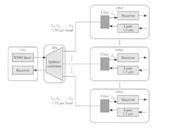
14 b. WDM PON: It is an upgraded version of the basic PON architecture. In this case, the CO broadcasts multiple wavelengths to all the ONU s and each ONU select a particular wavelength. In this case, a single transceiver at the CO with WDM array of transmitters or single tunable transmitter to yield (WDM PON). This approach allows each ONU s to have electronics running only at the rate it receives data, and not at the aggregate bit rate. However it is still limited by the power splitting at the star coupler. c. WR PON- Wavelength routing PON: In this case, a passive arrayed waveguide grating (AWG) is used to route different wavelength to different ONUS in the down stream directions, without is curring a splitting loss. AS in the TPON and WPON architectures, the ONUS time shared wavelength for Upstream transmission It allows point to point dedicated services to be provided to ONUS. FTTH: Fiber to the home IN FTTC ie Fiber to the curb (or) Fiber to the building, data is transmitted digitally over optical fiber from the hub, or central office, to fiber terminating nodes called optical network units(onu). The expectation is that fiber would get much closer to the subscriber with this architecture. IN FTTH (fiber to the home) architecture, the ONUS would perform the function of NIU. Here the optical fiber is used to transmit data from central office to remote node (RN) and RN to home. In network from the co to ONU is typically a passive optical network(pon). The remote node is a simple passive device such as an optical star coupler and it may some be collocated in the central office itself rather than in the field.
15 Although many different architectural alternatives can be used for FTTC, the term FTTC is usually used to describe a version where the signals are broadcast from the central office to the ONUS, and the ONUS share a common total bandwidth in time division multiplexed fashion. In FTTC, the fiber is within about 100m of the end user. In this case, there is an additional distribution network from the ONUS to the NIUS with the fiber to the cabinet (FTTcab) approach, the fiber is terminated in a cabinet in the neighbourhood and is within about 11cm of the end user. AON: All optical network Figure: A Helical LAN topology proposed to be used in the AON TDM All optical network (AON) consortium consisting of AT&T Bell laboratories, digital equipment co- operation and Massachusetts institute of technology developed a test bed for light wave communication. The aim of the test bed was to demonstrate a single routing mode in a network operating at a transmission rate of 100 bits/s. Packet interleaving was used and packets from electronic sources at 100 Mb/s were optically compressed to the 100 lib/s rate using optical time division multiplexing. AON supported different classes of service, specifically guaranteed bandwidth service and bandwidth-on-demand service. The topology used in the above diagram is bus topology where users transmit in the top half of the bus and receive from the bottom half. However, each user is attached for transmission to two points on the bus such that the guranteeded bandwidth transmission are always upstream from the bandwidth-on-demand transmission since it having helical shape, the name helical LAN(HLAN) for this network.
16 Wavelength division Multiplexing (WDM): A powerful aspect of an optical communication link is that many different wavelengths can be sent along a single fiber simultaneously in the 1300 to 1600nm spectral band. The technology of combining a number of wavelengths on to the same fiber is known as wavelength division multiplexing or WDN. Features of WDN: Capacity upgrade: If each wavelength support an independent network signal of perhaps a few giga bits per second, then WDN can increase the capacity of fiber optic network dramatically. Transparency: Using different wavelengths, fast (Or) slow asynchronous and synchronous digital data and analog information can be sent simultaneously and independently, over the same fiber, without the need for a common signal structure. Wavelength routing: The use of wavelength sensitive optical routing devices makes it possible to use wavelength as another dimension, in addition to the time and space in designing communication networks and switches. In wavelength routed networks, use the actual wavelength as intermediate (or) final address. Wavelength switching: Wavelength routed network-rigid configuration (can not be altered) Wavelength switched network (WSN): Allow the reconfiguration of optical network. Key components needed for WSN add drop multiplexed.optical cross connects and wavelength converters.
17 Operation principle of WDM. Figure: A Unidirectional WDM system that combines N independent input transmission over a single fiber signal for Figure : Schematic representation of a bidirectional WDM system Here N fibers come together at an optical combiner (or)wavelength multiplexer, each with its energy present at different wavelength. The N light beams are combined (or) multiplexed on to a single shared fiber for transmission to a distance destination. At far end, the beam is split up over many fibers as there were on the input side. Each output fiber contains a short, specially constructed core that filters act all but one wavelength. The resulting signals can be rated to their destination (or) recombined in different ways for additional multiplexed transport.
18 The only difference with electrical FDM is that on optical system using a diffraction grating is completely passive and thus highly reliable. The first commercial system had eight channels of 2.5 Gpbs per channel. By 2001,
19 there were products with 96 channels of 10 Gpbs, for a total of 960 Gbps. When the number of channels is very large and wavelength are spaced close together, for example 0.1nm, the system often referred to as DWDM (Dense WDM). By running many channels in parallel on different wavelength, the aggregate bandwidth is increased linearly with the no. of channels. Since the bandwidth of single fiber band is about 25,000 GHZ, there is theoretically room for GPPS channels even at 1 bit/hz. (for DWDM, write same explanation with the diagram)
S.R.M. University Faculty of Engineering and Technology School of Electronics and Communication Engineering
 S.R.M. University Faculty of Engineering and Technology School of Electronics and Communication Engineering Question Bank Subject Code : EC459 Subject Name : Optical Networks Class : IV Year B.Tech (ECE)
Access Networks. Based on: Optical Networks, a Practical Perspective (2 nd Edition) Chapter 11, by R.Ramaswami, K.N.Sivarajan
 Chapter 11, by R.Ramaswami, K.N.Sivarajan") Access Networks Based on: Optical Networks, a Practical Perspective (2 nd Edition) Chapter 11, by R.Ramaswami, K.N.Sivarajan Access Network! The network feeding the metro (and core) networks by gathering
Access Networks Based on: Optical Networks, a Practical Perspective (2 nd Edition) Chapter 11, by R.Ramaswami, K.N.Sivarajan Access Network! The network feeding the metro (and core) networks by gathering
Optical Fiber Communications. Optical Networks- unit 5
 Optical Fiber Communications Optical Networks- unit 5 Network Terminology Stations are devices that network subscribers use to communicate. A network is a collection of interconnected stations. A node
Simple Optical Network Architectures
 Simple Optical Network Architectures Point to Point Link The simplest optical communication system is that linking two points. The length of such links may be a small as 100 m for say, a computer data
Module 11 - Fiber Optic Networks and the Internet
 Module 11 - Fiber Optic Networks and the Internet Dr. Alan Kost Associate Research Professor Of Sciences, University Of Arizona Dr. Alan Kost is an Associate Research Professor of Sciences in the University
Introduction to Networks
 Introduction to Networks Network Topology How we interconnect network users Network Hierarchy The connection between network topology and geographical size Telecommunication (Phone Networks) Circuit Switching
Optical networking: is the Internet of the future already here?
 Optical networking: is the Internet of the future already here? Emilie CAMISARD Renater Optical technologies engineer - Advanced IP Services e-mail: camisard@renater.fr 23/11/04 ATHENS - Optical networking
WDM-PON Architecture Implement Using AWG with Multicasting Efficiency
 WDMPON Architecture Implement Using AWG with Multicasting Efficiency Nerkar Narendra N, Kadu Mahesh B Electronics and Telecommunication Department, AVCOE Sangamner, India. ABSTRACT: We present the experimental
Performance Analysis of Unidirectional and Bidirectional Broadband Passive Optical Networks
 Performance Analysis of Unidirectional and Bidirectional Broadband Passive Optical Networks Rini T. Jacob PG Scholar, Opto Electronics and Communication Systems, Dept. of Electronics and Communication
Optical Cards. 4.1 OC-N Cards OC-N Card Overview CHAPTER
 CHAPTER 4 This chapter describes the Cisco ONS 15454 optical card features and functions. It includes descriptions, hardware specifications, and block diagrams for each optical card. For installation and
Design of AWG-based WDM-PON Architecture with Multicast Capability
 e-issn 2455 1392 Volume 2 Issue 4, April 2016 pp. 33-40 Scientific Journal Impact Factor : 3.468 http://www.ijcter.com Design of AWG-based WDM-PON Architecture with Multicast Capability Suresh Aundekar1
CHAPTER TWO LITERATURE REVIEW
 CHAPTER TWO LITERATURE REVIEW 2.1 Introduction. This chapter provides in detail about the multiple access technologies and the OCDMA system. It starts with a discussion on various existing multiple-access
Optical networking technology
 1 Optical networking technology Technological advances in semiconductor products have essentially been the primary driver for the growth of networking that led to improvements and simplification in the
Introduction to Optical Networks
 Introduction to Optical Networks P. Michael Henderson mike@michael-henderson.us 1 Agenda The physics of light Laser and photodetector operation Characteristics of optical fiber Optical amplifiers SONET
Introduction To Optical Networks Optical Networks: A Practical Perspective
 Introduction To Optical Networks Optical Networks: A Practical Perspective Galen Sasaki Galen Sasaki University of Hawaii 1 Galen Sasaki University of Hawaii 2 Galen Sasaki University of Hawaii 3 Telecommunications
 DEPARTMENT OF ELECTRONICS AND COMMUNICATION ENGINEERING M.E., - COMMUNICATION SYSTEMS FIRST YEAR / FIRST SEMESTER - BATCH: 2014-2016 CU7103 OPTICAL NETWORKS 1 SYLLABUS CU7103 OPTICAL NETWORKS L T P C 3
Modems, DSL, and Multiplexing. CS158a Chris Pollett Feb 19, 2007.
 Modems, DSL, and Multiplexing CS158a Chris Pollett Feb 19, 2007. Outline Finish up Modems DSL Multiplexing The fastest modems Last day, we say the combinations and phases used to code symbols on a 2400
REVIEW ON WDM AND TDM PON USING DIFFERENT CODING SCHEMES FOR EXTENDED REACH
 REVIEW ON WDM AND TDM PON USING DIFFERENT CODING SCHEMES FOR EXTENDED REACH Pallavi Katna 1, Anu Sheetal 2 1,2 Guru Nanak Dev University, Regional Campus, Gurdaspur (Punjab) ABSTRACT Telecommunication
Beykent University Network Courses
 /8/24 Beykent University Network Courses Module 3 : Optical Networks and Systems Part kaanavsarasan.weebly.com November 24 November 24 Course Outline Introduction to Optics Components of Optical Networks
Designing Modern Optical Transport Networks
 Designing Modern Optical Transport Networks Course Description Fiber optic systems are a key part of new communications services. Their success depends upon good design. This course provides a basic understanding
10-Gigabit Ethernet DWDM OTN Optical Interface Specifications
 1-Gigabit Ethernet DWDM OTN Optical Interface Specifications M12 router and T Series routers support the following 1-Gigabit Ethernet DWDM OTN PIC transceiver. To determine DWDM OTN support, see the cables
Performance Evaluation of Qos for Multicast Streams in Optical Passive Networks
 Performance Evaluation of Qos for Multicast Streams in Optical Passive Networks 1 Deepak Malik, 2 Ankur Singhal 1,2 Dept. of ECE, MMEC, Mullana, India Abstract The intensification of traffic in the access
Communication Networks
 Communication Networks Chapter 3 Multiplexing Frequency Division Multiplexing (FDM) Useful bandwidth of medium exceeds required bandwidth of channel Each signal is modulated to a different carrier frequency
Real Time Implementation of Data Communication using Ipv4Telecom Network through Sdhstm-4 Digital Transmission Wan
 RESEARCH ARTICLE Real Time Implementation of Data Communication using Ipv4Telecom Network through Sdhstm-4 Digital Transmission Wan SharadaOhatkar*, Sanjay Thakare**, RachnaChavan*, Mugdha Kulkarni *,
10-Gigabit Ethernet DWDM OTN PIC Optical Interface Support (T640 Router)
") 1-Gigabit Ethernet DWDM OTN PIC Optical Interface Support (T64 Router) Table 1 describes the optical interfaces supported on the 1 Gigabit Ethernet DWDM OTN PIC. Table 1: Optical Interface Support for
1-Gigabit Ethernet DWDM OTN PIC Optical Interface Support (T64 Router) Table 1 describes the optical interfaces supported on the 1 Gigabit Ethernet DWDM OTN PIC. Table 1: Optical Interface Support for
AllWave FIBER BENEFITS EXECUTIVE SUMMARY. Metropolitan Interoffice Transport Networks
 AllWave FIBER BENEFITS EXECUTIVE SUMMARY Metropolitan Interoffice Transport Networks OFS studies and other industry studies show that the most economic means of handling the expected exponential growth
DWDM Topologies CHAPTER. This chapter explains Cisco ONS dense wavelength division multiplexing (DWDM) topologies.
 topologies.") CHAPTER 12 This chapter explains Cisco ONS 15454 dense wavelength division multiplexing (DWDM) topologies. Note The terms "Unidirectional Path Switched Ring" and "UPSR" may appear in Cisco literature.
CHAPTER 12 This chapter explains Cisco ONS 15454 dense wavelength division multiplexing (DWDM) topologies. Note The terms "Unidirectional Path Switched Ring" and "UPSR" may appear in Cisco literature.
Name of Course : E1-E2 CFA. Chapter 15. Topic : DWDM
 Name of Course : E1-E2 CFA Chapter 15 Topic : DWDM Date of Creation : 28.03.2011 DWDM 1.0 Introduction The emergence of DWDM is one of the most recent and important phenomena in the development of fiber
Chapter 8: Multiplexing
 NET 456 High Speed Networks Chapter 8: Multiplexing Dr. Anis Koubaa Reformatted slides from textbook Data and Computer Communications, Ninth Edition by William Stallings, 1 (c) Pearson Education - Prentice
Next Generation Requirements for DWDM network
 Next Generation Requirements for DWDM network Roman Egorov Verizon Laboratories May 3, 2011 Verizon copyright 2011. NG Requirements for DWDM network: Outline Optical Transport Network Metro vs. Long-Haul
Networks 15.2 Multiplexing Technologies Access Networks 15.5 Common Peripheral Interfaces
 Chapter 15 Computer and Multimedia Networks 15.11 Basics of Computer and Multimedia Networks 15.2 Multiplexing Technologies 15.3 LAN and WAN 15.4 Access Networks 15.5 Common Peripheral Interfaces 15.6
Lambda Networks DWDM. Vara Varavithya Department of Electrical Engineering King Mongkut s Institute of Technology North Bangkok
 Lambda Networks DWDM Vara Varavithya Department of Electrical Engineering King Mongkut s Institute of Technology North Bangkok vara@kmitnb.ac.th Treads in Communication Information: High Speed, Anywhere,
Passive Optical Networks: Fundamental Deployment Considerations
 white paper p age 1 of 7 Passive Optical Networks: Fundamental Deployment Considerations Abstract This paper provides a brief introduction to the subject of Passive Optical Networks (PONs) and discusses
Network Topologies & Error Performance Monitoring in SDH Technology
 Network Topologies & Error Performance Monitoring in SDH Technology Shiva Sharma Electronics and Communications Department Dronacharya College of Engineering Gurgaon, Haryana Shiva.92@hotmail.com Abstract
WaveReady Eight-Port Any Service OTN Muxponder WRM-8008T000B
 WaveReady Eight-Port Any Service OTN Muxponder WRM-8008T000B www.lumentum.com Data Sheet A flexible WDM transport solution The WRM-8008 is a next-generation OTN muxponder that can transparently aggregate
Global Ethernet Standards
 Fiber A Tutorial Overview Ethernet, which has been with us since 1980, has been the dominant enterprise LAN protocol for the last decade. Several popular Ethernet standards, including 10BASE-T and 100BASE-T
2000 Technology Roadmap Optoelectronics. John Stafford, Motorola January 17, 2001
 2000 Technology Roadmap Optoelectronics John Stafford, Motorola January 17, 2001 Optoelectronic Roadmap Agenda Optoelectronics Market Overview Optical Communications Roadmap Optical Communications Technology
EE 233. LIGHTWAVE. Chapter 5. Lightwave Systems
 EE 233. LIGHTWAVE SYSTEMS Chapter 5. Lightwave Systems Instructor: Ivan P. Kaminow 2/16/06 EE233. Prof Kaminow 1 SYSTEM ARCHITECTURES 2/16/06 EE233. Prof Kaminow 2 2/16/06 EE233. Prof Kaminow 3 POINT-TO-POINT
Internet Traffic Characteristics. How to take care of the Bursty IP traffic in Optical Networks
 Internet Traffic Characteristics Bursty Internet Traffic Statistical aggregation of the bursty data leads to the efficiency of the Internet. Large Variation in Source Bandwidth 10BaseT (10Mb/s), 100BaseT(100Mb/s),
E3-E4 (CFA) EPON & GPON. For BSNL internal circulation only
 EPON & GPON. For BSNL internal circulation only") E3-E4 (CFA) EPON & GPON AGENDA Limits of Present Access network. Passive Optical Network EPON / GEPON GPON Architecture PON Topology and services Conclusion PRESENT ACESS N/W ISDN HDSL ADSL ADSL2+ VDSL
E3-E4 (CFA) EPON & GPON AGENDA Limits of Present Access network. Passive Optical Network EPON / GEPON GPON Architecture PON Topology and services Conclusion PRESENT ACESS N/W ISDN HDSL ADSL ADSL2+ VDSL
Cisco MDS 9000 Family Pluggable Transceivers
 Cisco MDS 9000 Family Pluggable Transceivers The Cisco Small Form-Factor Pluggable (), and X2 devices for use on the Cisco MDS 9000 Family are hot-swappable transceivers that plug into ports on the Cisco
PA-POS-2OC3 Overview. The Cisco 7206 VXR router can be used as a router shelf in a Cisco AS5800 universal access server.
 :: Seite 1 von 6 :: Datenblatt zum Produkt Cisco 2 Port Packet/SONET mit DC# 437848 :: PA-POS-2OC3 Overview The PA-POS-2OC3 provides two Packet-over-SONET (POS) ports in a single port adapter slot. The
REDUCING CAPEX AND OPEX THROUGH CONVERGED OPTICAL INFRASTRUCTURES. Duane Webber Cisco Systems, Inc.
 REDUCING CAPEX AND OPEX THROUGH CONVERGED OPTICAL INFRASTRUCTURES Duane Webber Cisco Systems, Inc. Abstract Today's Cable Operator optical infrastructure designs are becoming more important as customers
Chapter - 7. Multiplexing and circuit switches
 Chapter - 7 Multiplexing and circuit switches Multiplexing Multiplexing is used to combine multiple communication links into a single stream. The aim is to share an expensive resource. For example several
Optical Networks. A Practical Perspective. Rajiv Ramaswami Kumar N. Sivarajan MORGAN KAUFMANN PUBLISHERS
 Optical Networks A Practical Perspective Second Edition Rajiv Ramaswami Kumar N. Sivarajan к MORGAN KAUFMANN PUBLISHERS AN IMPRINT OF ACADEMIC PRESS A Division of Harcourt, Inc. SAN FRANCISCO SAN DIEGO
Optimization for the Best Performance for Wavelength Division Multiplexed Passive Optical Network
 Proceedings of EnCon2008 2 nd Engineering Conference on Sustainable Engineering Infrastructures Development & Management December 18-19, 2008, Kuching, Sarawak, Malaysia Optimization for the Best Performance
learntelecoms interactive e-learning suite of courses: SyncNet v6 SDH-based broadband networks SyncNet
 Tel: 0845 0949 120 Email: info@ptt.co.uk Web site: www.ptt.co.uk SyncNet SyncNet v6 SDH-based broadband networks SyncNet is a suite of interactive, multimedia e-learning courses. provides training in the
Hands-On Fiber Optic Designer
 Hands-On Course Description Fiber optic systems are a key part of new communications services. Teir success depends upon good design. This Hands-On course will cover the particulars of how fiber optic
Deployment & Operations Committee. FTTH Basics Architecture, Topology and Technology
 Deployment & Operations Committee FTTH Basics Architecture, Topology and Technology FTTH Basics Architecture, Topology and Technology Moderator: Presenter: Rong Zhao Chair Deployment & Operations Committee
Wide Area Networks :
 Wide Area Networks : Backbone Infrastructure Ian Pratt University of Cambridge Computer Laboratory Outline Demands for backbone bandwidth Fibre technology DWDM Long-haul link design Backbone network technology
Networks 15.2 Multiplexing Technologies Access Networks 15.5 Common Peripheral Interfaces
 Chapter 15 Computer and Multimedia Networks 15.11 Basics of Computer and Multimedia Networks 15.2 Multiplexing Technologies 15.3 LAN and WAN 15.4 Access Networks 15.5 Common Peripheral Interfaces 15.6
Lecture 2 Physical Layer - Multiplexing
 DATA AND COMPUTER COMMUNICATIONS Lecture 2 Physical Layer - Multiplexing Mei Yang Based on Lecture slides by William Stallings 1 MULTIPLEXING multiple links on 1 physical line common on long-haul, high
A Novel Reconfigurable Ring Architecture of Multiple Secure Private Networks over EPON Using OCDMA Code-Drop Units
 A Novel Reconfigurable Ring Architecture of Multiple Secure Private Networks over EPON Using OCDMA Code-Drop Units Mohammad GHARAEI* a, Catherine LEPERS b, Ihsan FSAIFES b and Philippe GALLION a a Institut
SFP GBIC XFP. Application Note. Cost Savings. Density. Flexibility. The Pluggables Advantage
 SFP GBIC XFP The Pluggables Advantage interfaces in the same general vicinity. For example, most major data centers have large Ethernet (and Gigabit Ethernet) networks with copper, multimode and single-mode
Analysis of Next Generation PON Architecture for Optical Broadband Access Networks
 Abstract: Analysis of Next Generation PON Architecture for Optical Broadband Access Networks Manish Choudhary and Bipin Kumar Centre For Development of Telematics, Delhi Main Mandi Road, Chatterpur, Mehrauli,
Study of Bidirectional Broadband Passive Optical Network (BPON) Using EDFA
 Using EDFA") University of Denver Digital Commons @ DU Electronic Theses and Dissertations Graduate Studies 1-1-2014 Study of Bidirectional Broadband Passive Optical Network (BPON) Using EDFA Yasser A. Almalaq University
University of Denver Digital Commons @ DU Electronic Theses and Dissertations Graduate Studies 1-1-2014 Study of Bidirectional Broadband Passive Optical Network (BPON) Using EDFA Yasser A. Almalaq University
Optical Fiber for Today s Premises Applications
 Optical Fiber for Today s Premises Applications Tony Irujo Customer Technical Support Mgr. OFS Optical Fiber Division 508-347-8582 tirujo@ofsoptics.com 1 Copyright 2006 Fitel USA Corp., All rights reserved.
Electromagnetic Spectrum
 Electromagnetic Spectrum PCS FMRadi o/ TV Short wave Radi o AM Broadcast Ul trasoni c Soni c Vi si ble Li ght Infrared Li ght Ul travi ol et X- Rays Frequency 1 khz 1 M Hz 1 G Hz 1 THz 1 Y Hz 1 ZHz Wavelength
Optical Loss Budgets
 CHAPTER 4 The optical loss budget is an important aspect in designing networks with the Cisco ONS 15540. The optical loss budget is the ultimate limiting factor in distances between nodes in a topology.
IP over. Mario Baldi. Politecnico di Torino. (Technical University of Turin) IPinterconnection - 1 Copyright: si veda nota a pag.
 IPinterconnection - 1 Copyright: si veda nota a pag.") IP over ATM SDH DWDM Mario Baldi Politecnico di Torino (Technical University of Turin) www.baldi.info IPinterconnection - 1 Copyright: si veda nota a pag. 2 Nota di Copyright This set of transparencies,
IP over ATM SDH DWDM Mario Baldi Politecnico di Torino (Technical University of Turin) www.baldi.info IPinterconnection - 1 Copyright: si veda nota a pag. 2 Nota di Copyright This set of transparencies,
Physical Layer Part 3
 Physical Layer Part 3 Transmission Media Networks: Transmission Media 1 Transmission Media Transmission medium:: the physical path between transmitter and receiver. Repeaters or amplifiers may be used
A Scalable CWDM/TDM-PON network with future-proof elastic bandwidth
 A Scalable CWDM/TDM-PON network with future-proof elastic bandwidth STAMATIOS V. KARTALOPOULOS, PhD Williams Professor in Telecommunications Networking ECE Department, TCOM graduate program The University
Simply self-restored ring-based time-division-multiplexed passive optical network
 Vol. 7, No. 4 / April 2008 / JOURNAL OF OPTICAL NETWORKING 288 Simply self-restored ring-based time-division-multiplexed passive optical network C.-H. Yeh, 1, * C.-S. Lee, 1 and S. Chi 2,3 1 Information
DM16E1 Series II DM4E1 Series II
 DM16E1 Series II DM4E1 Series II Optical PDH Multiplexers Dec-2013 General Presentation The DM16E1 Series II and DM4E1 Series II are PDH multiplexers according G.751 e G.742. Operate with E1 multiplexer
OFFH-CDM ALL-OPTICAL NETWORK
 Patent Title: OFFH-CDM ALL-OPTICAL NETWORK Inventor: FOULI K., MENIF M., LADDADA R., AND FATHALLAH H. Status: US PATENT PENDING, APRIL 2008 Reference Number: 000819-0100 1 US Patent Pending: 000819-0100
Developing flexible WDM networks using wavelength tuneable components
 Developing flexible WDM networks using wavelength tuneable components A. Dantcha 1, L.P. Barry 1, J. Murphy 1, T. Mullane 2 and D. McDonald 2 (1) Research Institute for Network and Communications Engineering,
Multiplexing (Recap)
") Multiplexing (Recap) Multiplexing How to transfer data between two sites once there is a digital link between them? Analog to Digital (A2D) conversion Human voice is a continuous signal in the range 0-4
Multiplexing (Recap) Multiplexing How to transfer data between two sites once there is a digital link between them? Analog to Digital (A2D) conversion Human voice is a continuous signal in the range 0-4
Effects of using RZ and NRZ modulation formats for TDM-PON system on Transmission Characteristics for Downstream Signals
 Effects of using RZ and NRZ modulation formats for TDM-PON system on Transmission Characteristics for Downstream Signals Nimrat Kaur Sai Institute of Engg. & Tech, Amritsar, Punjab, India. Malti Sarangal
Course Details. Optical Networks. Grading. Course References. Outline of Course. Course Project. Jason Jue The University of Texas at Dallas
 Course Details Optical Networks Jason Jue The University of Texas at Dallas Instructor: Jason Jue E-mail: jjue@utdallas.edu URL: http://www.utdallas.edu/~jjue/optical/ Lectures: Thursday 2-5 pm Course
CSIS Frequency Division Multiplexing. Basic Types of Multiplexing. Frequency Division Multiplexing. Frequency Division Multiplexing.
 Multiplexing: combining information streams from multiple sources for transmission over a shared medium Demultiplexing: separating a combination back into individual information streams CSIS 4222 Ch 11:
Fibre Optic Communications - Networking
 Fibre Optic Communications - Networking Professor Chris Chatwin Module: Fibre Optic Communications MSc/MEng Digital Communication Systems UNIVERSITY OF SUSSEX SCHOOL OF ENGINEERING & INFORMATICS 1 st June
MileGate GPON. GPON Platform for FTTH/FTTB Applications
 MileGate GPON GPON Platform for Applications GPON Platform for Applications Content Infrastructure Advantages MileGate integrated GPON MileGate OLT Units MileGate ONT Units MileGate Infrastructure FTTH
Enhancing PON capabilities using the wavelength domain
 Enhancing PON capabilities using the wavelength domain Joint ITU/IEEE workshop on Next Generation Access, Geneva 2008 Thomas Pfeiffer, Alcatel-Lucent Bell Labs June 20, 2008 Introduction Optical fiber
Optical Networks Jean-Michel Dricot BEST Course
 Optical Networks Jean-Michel Dricot BEST Course - 2013 http://opera.ulb.ac.be/ Introduction 2/50 Tier-1 Core Network: the Internet Overall Internet traffic 500 TBytes/second. Capacity doubles every two
INTRODUCTION DATA COMMUNICATION TELECOMMUNICATIONS SYSTEM COMPONENTS 1/28/2015. Satish Chandra satish0402.weebly.com
 INTRODUCTION DATA COMMUNICATION Satish Chandra satish0402.weebly.com The term telecommunication means communication at a distance. The word data refers to information presented in whatever form is agreed
LAN Systems. Bus topology LANs
 Bus topology LANs LAN Systems Design problems: not only MAC algorithm, not only collision domain management, but at the Physical level the signal balancing problem (signal adjustment): Signal must be strong
PERFORMANCE ANALYSIS AND APPLICATIONS OF PASSIVE OPTICAL NETWORKS
 Özge GÜRE and N. Özlem ÜNVERDİ / IU-JEEE Vol. 14(2), (2014), 1843-1848 PERFORMANCE ANALYSIS AND APPLICATIONS OF PASSIVE OPTICAL NETWORKS Özge GÜRE 1, N. Özlem ÜNVERDİ 2 1,2 Yildiz Technical University,
DWDM Cards. 6.1 DWDM Card Overview CHAPTER
 CHAPTER 6 This chapter describes Cisco ONS 15454 dense wavelength-division multiplexing (DWDM) card features and functions. For installation and card turn-up procedures, refer to the Cisco ONS 15454 Procedure
Performance Evaluation of the Maximum Achievable Bit Rate of a Next Generation TWDM Passive Optical Network
 American Journal of Engineering Research (AJER) e-issn: 2320-0847 p-issn : 2320-0936 Volume-5, Issue-12, pp-104-109 www.ajer.org Research Paper Open Access Performance Evaluation of the Maximum Achievable
Optical Networks: A Practical Perspective
 Optical Networks: A Practical Perspective Rajiv Ramaswami Tellabs, Inc. Kumar N. Sivarajan Indian Institute of Science 14 Morgan Kaufmann Publishers, Inc. San Francisco, California Contents Foreword vii
UNIT- 2 Physical Layer and Overview of PL Switching
 UNIT- 2 Physical Layer and Overview of PL Switching 2.1 MULTIPLEXING Multiplexing is the set of techniques that allows the simultaneous transmission of multiple signals across a single data link. Figure
Multiple Access Techniques for epon. Glen Kramer
 Multiple Access Techniques for epon len Kramer glen.kramer@alloptic.com IEEE 802.3 EFM Study roup Meeting, March 2001 First Mile LAN HAVE Non-cooperative (independent) users Non-uniform traffic: most traffic
UNIT-II OVERVIEW OF PHYSICAL LAYER SWITCHING & MULTIPLEXING
 1 UNIT-II OVERVIEW OF PHYSICAL LAYER SWITCHING & MULTIPLEXING Syllabus: Physical layer and overview of PL Switching: Multiplexing: frequency division multiplexing, wave length division multiplexing, synchronous
1. INTRODUCTION light tree First Generation Second Generation Third Generation
 1. INTRODUCTION Today, there is a general consensus that, in the near future, wide area networks (WAN)(such as, a nation wide backbone network) will be based on Wavelength Division Multiplexed (WDM) optical
Multiformat Home Networks using Silica Fibres
 Multiformat Home Networks using Silica Fibres Orange Labs Ph. Guignard, J. Guillory, Ph. Chanclou, A. Pizzinat, O. Bouffant, N. Evanno, J. Etrillard, B. Charbonnier, S. Gosselin, L. Guillo, F. Richard.
Physical Layer Part 3
 Physical Layer Part 3 Transmission Media Computer Networks: Transmission Media 1 Transmission Media Transmission medium:: the physical path between transmitter and receiver. Repeaters or amplifiers may
Fiber-Wireless (FiWi) Access Networks
 Access Networks") Fiber-Wireless (FiWi) Access Networks Eiman Alotaibi Department of Computer Science University of California, Davis Reference: N. Ghazisaidi, M. Martin, and C. Assi, Fiber-Wireless (FiWi) Access Networks:
Fiber-Wireless (FiWi) Access Networks Eiman Alotaibi Department of Computer Science University of California, Davis Reference: N. Ghazisaidi, M. Martin, and C. Assi, Fiber-Wireless (FiWi) Access Networks:
UNIT - 8 OPTICAL AMPLIFIERS AND NETWORKS
 UNIT - 8 OPTICAL AMPLIFIERS AND NETWORKS Optical amplifiers, basic applications and types, semiconductor optical amplifiers, EDFA. Optical Networks: Introduction, SONET / SDH, Optical Interfaces, SONET/SDH
FIBER OPTIC NETWORK TECHNOLOGY FOR DISTRIBUTED LONG BASELINE RADIO TELESCOPES
 Experimental Astronomy (2004) 17: 213 220 C Springer 2005 FIBER OPTIC NETWORK TECHNOLOGY FOR DISTRIBUTED LONG BASELINE RADIO TELESCOPES D.H.P. MAAT and G.W. KANT ASTRON, P.O. Box 2, 7990 AA Dwingeloo,
Network Evolution Driving forces and influences on the physical Network
 Network Evolution Driving forces and influences on the physical Network Agenda Network Evolution New IEC Standards for FO connectivity NGON New Generation Optical Networks 15 Years ago and today s VISIONS
OPTICAL NETWORKS. Optical Metro Networks. A. Gençata İTÜ, Dept. Computer Engineering 2005
 OPTICAL NETWORKS Optical Metro Networks A. Gençata İTÜ, Dept. Computer Engineering 2005 Introduction Telecommunications networks are normally segmented in a three-tier hierarchy: Access, metropolitan,
Optical Fiber Networks: Industry. and New Options for Networks
 Optical Fiber Networks: Industry Trends, Application Influences and New Options for Networks Herbert V Congdon II, PE Manager, Standards & Technology Tyco Electronics AMP NETCONNECT Solutions Preview Deciding
Lecture 15: Multiplexing (2)
") Lecture 15: Multiplexing (2) Last Lecture Multiplexing (1) Source: chapter 8 This Lecture Multiplexing (2) Source: chapter8 Next Lecture Circuit switching (1) Source: chapter9 Digital Carrier Systems Hierarchy
Lecture 15: Multiplexing (2) Last Lecture Multiplexing (1) Source: chapter 8 This Lecture Multiplexing (2) Source: chapter8 Next Lecture Circuit switching (1) Source: chapter9 Digital Carrier Systems Hierarchy
PSTN, NGA and cable access networks compared: a technical perspective
 FACULTE D INFORMATIQUE 1/20 PSTN, NGA and cable access networks compared: a technical perspective L. Schumacher (FUNDP The University of Namur) CLEC Seminar, September 30 th, 2010 FACULTE D INFORMATIQUE
Emerging Architectures for Optical Broadband Access Networks
 Emerging Architectures for Optical Broadband Access Networks Rong Zheng and Daryoush Habibi The School of Engineering and Mathematics Edith Cowan University Perth, WA 6026 Email: r.zheng@ecu.edu.au, d.habibi@ecu.edu.au
Part 2! Physical layer! Part2: Lecture 01! Optical technologies! Part2: Lecture 01! Optical technologies! 19/04/16
 Part 2 Part2: Lecture 01 Optical technologies Optical networks: Technologies Hybrid networking, network virtualization Traffic engineering (Marijke Kaat) OpenFlow and SURFnet (Ronald van der Pol) Physical
Outline. Designing and measuring PON Conclusions. WDM-PON advantages & challenges AWG router transmitter sources - wavelength specific & colorless ONU
 Outline Introduction history (ISDN, xdsl, cable modem) economic considerations (bandwidth, cost) PON Architecture FTTx TDM-PON OLT & ONU, burst mode, DBA, ranging, security APON, EPON, GPON, SuperPON WDM-PON
Next Generation Optical Access Networks: A Review
 Next Generation Optical Access Networks: A Review Avneet Kaur Baljeet Kaur Kuldeepak Singh ABSTRACT Passive Optical Networks (PONs) represent one of the most attractive access network solutions. As the
Chapter 9. High Speed Digital Access
 Chapter 9 High Speed Digital Access 9-1 TELEPHONE NETWORK Telephone networks use circuit switching. The telephone network had its beginnings in the late 1800s. The entire network, which is referred to
Gigabit Ethernet Passive Optical Network (GEPON) Tutorial. June 2004
 Tutorial. June 2004") Gigabit Ethernet Passive Optical Network (GEPON) Tutorial June 2004 1 Ethernet Passive Optical Network (EPON) Tutorial OVERVIEW... 2 EPON TOPOLOGIES... 4 EPON NETWORK... 4 EPON SYSTEMS... 5 EPON PROTOCOL...
Gigabit Ethernet Passive Optical Network (GEPON) Tutorial June 2004 1 Ethernet Passive Optical Network (EPON) Tutorial OVERVIEW... 2 EPON TOPOLOGIES... 4 EPON NETWORK... 4 EPON SYSTEMS... 5 EPON PROTOCOL...