INFN - Thermal analysis of crate with motherboards, daughterboards and AM chips
|
|
|
- Simon Quinn
- 5 years ago
- Views:
Transcription


1 INFN - Thermal analysis of crate with motherboards, daughterboards and AM chips intermediate report Jan Bienstman Phone: Jan.Bienstman@imec.be IMEC, Kapeldreef 75 B3001 Heverlee date : 14/10/2014 Version :01 1/22
2 Content Content Modeling of the system Used data for the model... 3 Crate... 3 Fan... 3 Motherboard... 3 Daughterboard... 3 AM chip Hierarchical modeling Description of the model... 4 Crate... 4 Fan... 4 Motherboard... 5 Daughterboard... 6 AM chip... 6 Full top level system Thermal properties, power sources and thermal boundary conditions Simulation results Results top level simulation Top level simulation discussion Zoom-in box simulation /22
3 1. Modeling of the system 1.1. Used data for the model Crate Fan STEP file (PISA Bin.STEP) with model received on 26/08/2014 from Dirk Güßgen from Wiener e-drawing (PISA Bin.EASM) for visual verification 4114 NH4 - DC axial compact fan from ebmpapst Fan specification received on 26/08/2014 from Dirk Güßgen from Wiener (link, pdf) Fan curve in graph format digitized using excel sheet (Fan_Pressure-flow_curve.xlsx) Motherboard ODB++ directory (EDA V3-0_odb) in EDA V3-0_assy.zip received on 10/07/2014 from Paola Giannetti (link) ODB++ data was read by Sherlock from which geometric data was exported into Ansys (apdl) (only largest components and components which generate heat). Ansys apdl data was imported into Ansys Workbench and subsequently into Ansys Icepak. PCB layers and holes are directly read from ODB++ into Ansys Icepak Daughterboard ODB++ file (lambspl_odb.zip) received on 21/07/2014 from Paola Giannetti (link) ODB++ data was read by Sherlock from which geometric data was exported into Ansys (apdl) (only largest components and components which generate heat). Ansys apdl data was imported into Ansys Workbench and subsequently into Ansys Icepak. PCB layers and holes are directly read from ODB++ into Ansys Icepak AM chip Geometrical data based on AM05 package (HS FBGA_25x25_529L_021014_(Security B).pdf) received on 16/06/2014 from Paola Giannetti Other properties as in file (AM06_Package_Properties.xlsx) 1.2. Hierarchical modeling In order to be able to create a prediction of the temperatures at the AM chips, taking into account the full environment of the crate and fan flow, a hierarchical modeling approach is used. It is hardly possible to model and simulate features which differ five orders of magnitude (Crate ~1m versus RDL layer ~10µm) in one model and would cost a huge amount of memory, processing power and time. The modeling approach used consists of two steps: 1. The top level models the crate with boards and focusses on the air flow. The CAD geometry is simplified in order to create a reasonable mesh. Components are modeled as homogeneous rectangular blocks. Smaller components are neglected. The result of this simulation is a good approximation of the air flow in the crate and at the components of interest. This gives also insight in how the placement of boards and components affect the flow. Although the accompanying temperature results give a good insight in the temperature distribution, care should be taken in interpreting the values too quantitative. Because components are modelled as homogeneous blocks, the actual temperature will differ. When the internal heat source is very local, the actual temperature might be higher. In case that a component has better conductance to the air flow (e.g. with a metal case), the actual temperature will be lower. 2. A zoom-in box is defined around a region of interest (e.g. one motherboard). The results of the top level simulation at the boundaries of the zoom-in box are subsequent applied as boundary conditions to a more detailed model inside the box which replaces the first top level model. 3/22


4 1.3. Description of the model The following describes the modeling and simplification of the different parts in order to assess the accuracy of the results. Crate Figure 1: e-drawing of the crate Figure 2: Left: Imported model in Ansys Design Modeler. Right: Model of the front part of the crate in Icepak. As can be seen from the figures above, only the front part of the crate, where the motherboards sit, is modeled. Non-essential geometries are simplified as much as possible by rectangular shapes. The backplane connectors are lumped into one block. As an example, the figure below presents the original CAD shape of the cardslots for holding the motherboards and the supporting rails with snap-in attachment. The figures left show the simplification via Ansys DesignModeler into Ansys Icepak. Note that the fan s CAD geometry is also replaced by a 3D-fan object in Icepak. Fan Figure 3: Detail showing simplification process: Left: Original CAD, mid: model in DesignModeler, Right: model in Icepak. 4/22

, Right: simplified model (represented in Icepak).")
 to improve meshing. Also, height of the different components is adapted to become more uniform.")
5 The fans are modeled as Icepak 3D fans which models the geometry, hub power and the non-linear flow curve extracted from the fan specification (pdf) Figure 4: Left: Flow curve from manufacturer. Right: implemented flow curve in Fan model in Icepak. Motherboard A similar simplification procedure was done on the motherboard. Only the large, high and/or hot parts are retained for modeling. Two versions of the motherboard are used: the top level model, with more simplifications and the detailed model for the zoom-in model. Figure 5 presents the two models for the motherboard. Figure 5: Motherboard model: Left: detailed model (represented in Designmodeler), Right: simplified model (represented in Icepak). With respect to the detailed motherboard (left in Figure 5), the top level model of the motherboard (right in Figure 5) introduces more simplifications: The smallest parts are removed, some components are lumped together. Other components are slightly adapted (resized or moved) to improve meshing. Also, height of the different components is adapted to become more uniform. This is necessary for the meshing and simulation of 21 boards altogether with the crate. The top level model of the motherboard does not contain the copper traces in the PCB. For the SSB and VME board, an even more simplified model is used. It models the PCB and some connectors, and lumps all other (unknown) components into one large layer modeling air flow restriction. 5/22


6 Daughterboard Figure 6: Model for the SSB or VME boards. Analogue to the motherboard, the daughter board is more simplified in the top level model than in the zoom-in model. The top level model only contains the PCB, the central connector, the AM chips and four screws/standoffs. The PCB does not contain layout traces nor via s in the top level model. Figure 7: Daughterboard model: Left: detailed model (represented in Designmodeler), Right: simplified model (represented in Icepak). AM chip The AM chips are modeled as homogeneous blocks in the top level model. For the more detailed model, a compact model (available in Icepak) is chosen which models the chip as in Figure 8. Figure 8:Compact model for flip-chip BGA It is also possible to create a full 3D model of the package if more insight in the heat distribution is needed. 6/22

. Figure 10: Left: Side view of crate.")
7 Full top level system Figure 9 shows the front view of the total system. Figure 9: Front view of the crate, left, showing envelop of the motherboards, right, motherboards with daughterboards and components. (See Figure 11 for numbering of motherboards). Figure 10: Left: Side view of crate. Right: perspective view showing one motherboard with daughterboards. 7/22

8 1.4. Thermal properties, power sources and thermal boundary conditions The following thermal properties were used/assumed: power density Specific heat conductivity Material W kg/m³ J/kg-K W/m-K Metal parts parts of the crate: walls, plates, rails ,0 Al-Extruded screws between motherboard and daughterboard ,4 Steel-Stainless Plastic parts J* Connectors ,25 Nylon-Nylon-6 Backplane connectors motherboards slots C* Capacitors LD* LED's PCB's ,35 FR4 PCB* motherboards daughterboards 2,2 backplane SSB & VME board Components AM chips 3, C=61 for T < 77 C 15,0 Ceramic_material DCDC1 7,2 C=61+(T-77)*2,87 IC* IC22, IC59 3,0 for T >77 C IC41, IC43, IC49-53, IC ,0 PWR* PWR1, PWR2, PWR3 5,0 RG* RG1, RG2, RG3, RG4 6,5 Lumped components for SSB and VME boards 80,0 Custom Special motherboard-daughterboard connector ,1 DB_Connector _equivalent_material DB* (daughterboard) J3*, J4*, J6*, J7* (motherboard) Specific parts value unit Fans Hub power 30,0 W Rotation speed 6800 rpm Model border left, right, front, back heat transfer coeficient 10,0 W/K-m² calculated equivalent properties based on ratio pins/plastic 2. Simulation results 2.1. Results top level simulation Figure 12 depicts the simulated flow field by way of stream lines. Such stream lines gives a good intuitive indication of the flow but is less usable for qualitative interpretation. In the figures following Figure 13, a cross section through the crate at various position is used showing contour plots of the flow intensity and the temperature. Figure 13 shows the location of the different cross sections. The color legend uses the global limits as outer levels and is valid for all the subsequent figures. For illustration purpose, motherboard 10 is outlined on the contour plot of the flow speed while motherboard 09 is outlined on the temperature contour plot. The VME and SSB boards are also outlined. (See Figure 11 for numbering of motherboards). Figure 11: Numbering of motherboards in the crate (compare with Figure 9) 8/22


9 Figure 12: streamline plot of flow. Left: Side view of crate. Right: front view Figure 13: Position and number of the different cross sections. 9/22
 and temperature")


10 Figure 14: Contour plot of flow intensity (left) and temperature (right) at position 01, this is through the first row of AM-chips.(see Figure 13 for indication of position). The color legend shows the global limits and is valid for all the next figures. 10/22
 and temperature (right) at")


11 Figure 15: Contour plot of flow intensity (left) and temperature (right) at position 02 through the 2 nd row AM-chips. Figure 16: Contour plot of flow intensity (left) and temperature (right) at position 03 through the daughterboard connector. 11/22
 and temperature (right) at position 05 through the 4 th row AM chips.")
12 Figure 17: Contour plot of flow intensity (left) and temperature (right) at position 04 through the 3 rd row AM chips. Figure 18: Contour plot of flow intensity (left) and temperature (right) at position 05 through the 4 th row AM chips. 12/22
 and")


13 Figure 19: Contour plot of flow intensity (left) and temperature (right) at position 06 between daughterboards. Figure 20: Contour plot of flow intensity (left) and temperature (right) at position 07 between daughterboards. 13/22
 and")


14 Figure 21: Contour plot of flow intensity (left) and temperature (right) at position 08 through the 5 th row AM chips. Figure 22: Contour plot of flow intensity (left) and temperature (right) at position 09 through the 6 th row AM chips. 14/22
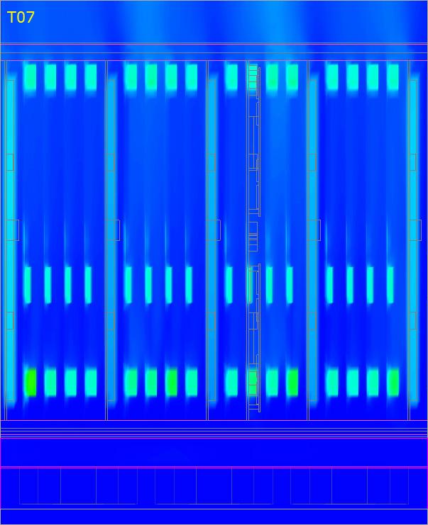
15 Figure 23: Contour plot of flow intensity (left) and temperature (right) at position 10 through the daughterboard connector. Figure 24: Contour plot of flow intensity (left) and temperature (right) at position 11 through the 7 th row AM chips. 15/22
 and temperature (right) at position 13 through the backplane connector. 2.2. Top level simulation discussion It should be noted that, as stated above, this top level simulation focusses on the flow.")

, the actual temperature will be lower. 16/22")
16 Figure 25: Contour plot of flow intensity (left) and temperature (right) at position 12 through the 8 th row AM chips. Figure 26: Contour plot of flow intensity (left) and temperature (right) at position 13 through the backplane connector Top level simulation discussion It should be noted that, as stated above, this top level simulation focusses on the flow. Although the accompanying temperature results give a good insight in the temperature distribution, care should be taken in interpreting the values too quantitative. Because components are modelled as homogeneous blocks, the actual temperature will differ. When the internal heat source is very local, the actual temperature might be higher. In case that a component has better conductance to the air flow (e.g. with a metal case), the actual temperature will be lower. 16/22

17 The first conclusions that can be drawn is that the motherboards that sit between the fans have less air flow. This is indicated by arrows in fig x for the cross section at location 05, which is through the 4 th row AM chips. As a result, they show higher temperatures at equivalent places with respect to other motherboards. A second result is that some regulator components block the air flow for AM-chips. Because the regulator dissipates relative high power (6,5W assumed), subsequent components see less flow at higher temperatures. Worst situation occurs for the AM chip, which is 2 nd in a row after a regulator block for the motherboard which sits in between fans. Figure 27: Contour plot of flow intensity at position 05 through the 4th row AM chips.(see Figure 18). Air flow speed is lower in region between fans, this is at motherboards 05 and 10. The insets indicate position of next detailed figures () 17/22
18 Figure 28: Corresponding contour plot of temperature at position 05.(See figure above and Figure 18). Due to lower air flow speed in region between fans, the temperature of components is higher. 18/22


19 Figure 29: Temperature and flow plot corresponding to the red inset in Figure 27. Due to the closeness of the hot regulator, the AM chip following the regulator and neighboring AM chip has the highest temperature. 19/22


20 Figure 30: Temperature and flow plot corresponding to the black inset in Figure /22


21 Figure 31: Motherboard 05 PCB temperature contour plot. Left: component side. Right: backside Figure 32: Daughterboards for 05 motherboard: PCB temperature contour plot. Left: AM-chip side. Right: backside Figure 33: View on motherboard 05 and on back side of AM chips (daughterboard pcb hidden) 21/22
22 2.3. Zoom-in box simulation With the results of the previous simulation, a more detailed simulation in a region of interest around one motherboard is performed. The air flow at the boundaries is applied to a more detailed model, where AM-chips and some important components are more accurate modeled. Ongoing... 22/22
Realize Your Product Promise. Icepak
 Realize Your Product Promise Icepak ANSYS Icepak delivers powerful technology for electronics thermal management. Simulating high-performance electronics cooling readily solves challenges in this rapidly
Thermal Management of Electronics in Drilling and Completion. Gokul V Shankaran
 Thermal Management of Electronics in Drilling and Completion Gokul V Shankaran 1 Background Electronics circuitry in down hole tools to collect sensors data, drive actuators, multiplexing, data storage
ANSYS, Inc. March 3, 2016 PCB 板极电热耦合分析及对电子设备热设计的影响
 1 2015 ANSYS, Inc. March 3, 2016 PCB 板极电热耦合分析及对电子设备热设计的影响 Printed Circuit Board Reliability Real world operating conditions = Multiphysics environment Electrical Reliability Power and Signal Integrity
ANSYS Workbench Guide
 ANSYS Workbench Guide Introduction This document serves as a step-by-step guide for conducting a Finite Element Analysis (FEA) using ANSYS Workbench. It will cover the use of the simulation package through
Thermo Mechanical Modeling of TSVs
 Thermo Mechanical Modeling of TSVs Jared Harvest Vamsi Krishna ih Yaddanapudi di 1 Overview Introduction to Through Silicon Vias (TSVs) Advantages of TSVs over wire bonding in packages Role of TSVs in
First Steps - Conjugate Heat Transfer
 COSMOSFloWorks 2004 Tutorial 2 First Steps - Conjugate Heat Transfer This First Steps - Conjugate Heat Transfer tutorial covers the basic steps to set up a flow analysis problem including conduction heat
Finite Element Analysis using ANSYS Mechanical APDL & ANSYS Workbench
 Finite Element Analysis using ANSYS Mechanical APDL & ANSYS Workbench Course Curriculum (Duration: 120 Hrs.) Section I: ANSYS Mechanical APDL Chapter 1: Before you start using ANSYS a. Introduction to
Beat the Heat in Notebooks with Software
 Beat the Heat in Notebooks with Software Computational fluid dynamics software can help you solve system-level thermal packaging problems. Pentium-class portables present significant packaging problems.
Electronics Cooling Using Conduction Convection Radiation from Heat Sinks to Heat Pipes - CFD Consulting Services
 Electronics Cooling Using Conduction Convection Radiation from Heat Sinks to Heat Pipes - CFD Consulting Services Predictive Engineering s CFD Consulting Experience Electronics cooling can be as simple
Temperature Analysis of Intel Server by using CFD and Experimentation
 Temperature Analysis of Intel Server by using CFD and Experimentation Chetan A Gawande 1, Prof. S.M. Nakate 2, Prasad Chavan 3 ¹Dept. of Mechanical engineering, MIT Pune, Pune University, pune India ²Dept.
Release Notes Version 5
 Release Notes Version 5 Version 5.1 (2017-01-31) Solder Joint Fatigue Calculix Support for Column Grid Array (CGA) modeling for Solder Joint Fatigue FEA analysis and the Solder Fatigue tool has been added
Thermal Performance Analysis of Intel workstation Server using CFD
 Thermal Performance Analysis of Intel workstation Server using CFD #1 Chetan A Gawande, #2 Prof. S.M. Nakate ¹Dept. of Mechanical engineering, MIT Pune, Pune University, pune India ²Dept. of Mechanical
Non-Isothermal Heat Exchanger
 Non-Isothermal Heat Exchanger The following example builds and solves a conduction and convection heat transfer problem using the Heat Transfer interface. The example concerns a stainless-steel MEMS heat
CFD Simulation of Air Flow and Thermal Behavior of Electronics Assembly within Plastic Enclosure for Outdoor Environments
 Keywords: CFD Simulation, Computational Fluid Dynamics, CFD conjugate heat transfer, CFD natural convection, CFD PCB simulation, CFD electronics enclosures, CFD ASICS, thermal predictions of electronic
ANSYS AIM Tutorial Fluid Flow Through a Transition Duct
 ANSYS AIM Tutorial Fluid Flow Through a Transition Duct Author(s): Sebastian Vecchi, ANSYS Created using ANSYS AIM 18.1 Problem Specification Start Up Geometry Import Geometry Extracting Volume Suppress
STEPS BY STEPS FOR THREE-DIMENSIONAL ANALYSIS USING ABAQUS STEADY-STATE HEAT TRANSFER ANALYSIS
 UNIVERSITI MALAYSIA PERLIS FACULTY OF ENGINEERING TECHNOLOGY DEPARTMENT OF MECHANICAL ENGINEERING TECHNOLOGY PDT348 FINITE ELEMENT ANALYSIS Semester II 2017/2018 STEPS BY STEPS FOR THREE-DIMENSIONAL ANALYSIS
CAMAC CERN CE 600W. Main Features. Request Quote
 CERN CE 600W Request Quote CERN-CE 600W WIENER offers a line of modular designed crates compliant with ESONE and CERN standards. This crates series is configured with 600W 650W linear regulated, low noise
Abstract. Die Geometry. Introduction. Mesh Partitioning Technique for Coextrusion Simulation
 OPTIMIZATION OF A PROFILE COEXTRUSION DIE USING A THREE-DIMENSIONAL FLOW SIMULATION SOFTWARE Kim Ryckebosh 1 and Mahesh Gupta 2, 3 1. Deceuninck nv, BE-8830 Hooglede-Gits, Belgium 2. Michigan Technological
ABAQUS for CATIA V5 Tutorials
 ABAQUS for CATIA V5 Tutorials AFC V2.5 Nader G. Zamani University of Windsor Shuvra Das University of Detroit Mercy SDC PUBLICATIONS Schroff Development Corporation www.schroff.com ABAQUS for CATIA V5,
Middle East Technical University Mechanical Engineering Department ME 413 Introduction to Finite Element Analysis Spring 2015 (Dr.
 Middle East Technical University Mechanical Engineering Department ME 413 Introduction to Finite Element Analysis Spring 2015 (Dr. Sert) COMSOL 1 Tutorial 2 Problem Definition Hot combustion gases of a
Verification of Laminar and Validation of Turbulent Pipe Flows
 1 Verification of Laminar and Validation of Turbulent Pipe Flows 1. Purpose ME:5160 Intermediate Mechanics of Fluids CFD LAB 1 (ANSYS 18.1; Last Updated: Aug. 1, 2017) By Timur Dogan, Michael Conger, Dong-Hwan
Table of Content. Part I Introduction
 3.5 External HDD Enclosure Transform any 3.5 internal hard drive into a high-speed and mobile storage device. User s Manual P/N: ST0008U & ST0010U Table of Content Part I Introduction 1.1 Overview--------------------------------------
Determination of the solicitation types responsible for the deformed. shape of an aircraft cockpit
 Determination of the solicitation types responsible for the deformed shape of an aircraft cockpit Infante, V. 1*, Gomes, E. 1 and Branco, C.M. 1 1 Departamento de Engenharia Mecânica, Instituto Superior
Simulation of Turbulent Flow over the Ahmed Body
 1 Simulation of Turbulent Flow over the Ahmed Body ME:5160 Intermediate Mechanics of Fluids CFD LAB 4 (ANSYS 18.1; Last Updated: Aug. 18, 2016) By Timur Dogan, Michael Conger, Dong-Hwan Kim, Maysam Mousaviraad,
Installation Guide. Beginners guide to structural analysis
 Installation Guide To install Abaqus, students at the School of Civil Engineering, Sohngaardsholmsvej 57, should log on to \\studserver, whereas the staff at the Department of Civil Engineering should
Lab 9: FLUENT: Transient Natural Convection Between Concentric Cylinders
 Lab 9: FLUENT: Transient Natural Convection Between Concentric Cylinders Objective: The objective of this laboratory is to introduce how to use FLUENT to solve both transient and natural convection problems.
Release Highlights. Software Version 6.1 December 27, Copyright 2018 DfR Solutions All rights reserved
 Release Highlights Software Version 6.1 December 27, 2018 Copyright 2018 DfR Solutions All rights reserved 9000 Virginia Manor Rd. Suite 290 Beltsville, MD 20705 301.474.0607 dfrsolutions.com sherlock.dfrsolutions.com
ANSYS AIM Tutorial Structural Analysis of a Plate with Hole
 ANSYS AIM Tutorial Structural Analysis of a Plate with Hole Author(s): Sebastian Vecchi, ANSYS Created using ANSYS AIM 18.1 Problem Specification Pre-Analysis & Start Up Analytical vs. Numerical Approaches
Simulation and Validation of Turbulent Pipe Flows
 Simulation and Validation of Turbulent Pipe Flows ENGR:2510 Mechanics of Fluids and Transport Processes CFD LAB 1 (ANSYS 17.1; Last Updated: Oct. 10, 2016) By Timur Dogan, Michael Conger, Dong-Hwan Kim,
Similar Pulley Wheel Description J.E. Akin, Rice University
 Similar Pulley Wheel Description J.E. Akin, Rice University The SolidWorks simulation tutorial on the analysis of an assembly suggested noting another type of boundary condition that is not illustrated
Crossing the Chasm Between ECAD and CAE Virginia Manor Road, Suite 290, Beltsville MD
 Crossing the Chasm Between ECAD and CAE 1 Who is DfR Solutions? The Industry Leader in Quality-Reliability-Durability of Electronics 50 Fastest Growing Companies in the Electronics Industry - Inc Magazine
Release Highlights for BluePrint-PCB Product Version 3.0
 Release Highlights for BluePrint-PCB Product Version 3.0 Introduction BluePrint V3.0 Build 568 is a rolling release, containing defect fixes for 3.0 functionality. Defect fixes for BluePrint V3.0 Build
Practice to Informatics for Energy and Environment
 Practice to Informatics for Energy and Environment Part 3: Finite Elemente Method Example 1: 2-D Domain with Heat Conduction Tutorial by Cornell University https://confluence.cornell.edu/display/simulation/ansys+-+2d+steady+conduction
2010 ANSYS, Inc. All rights reserved. 1 ANSYS, Inc. Proprietary
 Bi-directional Automatic Electromagnetic-Thermal Coupling for HEV/EV Traction Motor Design Using Maxwell and ANSYS Mechanical Peng Yuan Eric Lin Zed (Zhangjun) Tang ANSYS, Inc. 2010 ANSYS, Inc. All rights
Convection Cooling of Circuit Boards 3D Natural Convection
 Convection Cooling of Circuit Boards 3D Natural Convection Introduction This example models the air cooling of circuit boards populated with multiple integrated circuits (ICs), which act as heat sources.
ANSYS AIM 16.0 Overview. AIM Program Management
 1 2015 ANSYS, Inc. September 27, 2015 ANSYS AIM 16.0 Overview AIM Program Management 2 2015 ANSYS, Inc. September 27, 2015 Today s Simulation Challenges Leveraging simulation across engineering organizations
Preparing the Board for Design Transfer. Creating and Modifying the Board Shape. Modified by Phil Loughhead on 15-Aug-2016
 Preparing the Board for Design Transfer Old Content - visit altium.com/documentation Modified by Phil Loughhead on 15-Aug-2016 This article describes how to prepare the new PCB file so that it is ready to
QSFP-DD: Enabling 15 Watt Cooling Solutions
 QSFP-DD MSA QSFP-DD: Enabling 15 Watt Cooling Solutions White Paper Mark Nowell: Cisco Attila Aranyosi, Vu Le, Jeffery J. Maki: Juniper Networks Scott Sommers, Tom Palkert, Weiming Chen: Molex 3/12/2018
Modeling Evaporating Liquid Spray
 Tutorial 17. Modeling Evaporating Liquid Spray Introduction In this tutorial, the air-blast atomizer model in ANSYS FLUENT is used to predict the behavior of an evaporating methanol spray. Initially, the
Simulation of Turbulent Flow around an Airfoil
 Simulation of Turbulent Flow around an Airfoil ENGR:2510 Mechanics of Fluids and Transfer Processes CFD Pre-Lab 2 (ANSYS 17.1; Last Updated: Nov. 7, 2016) By Timur Dogan, Michael Conger, Andrew Opyd, Dong-Hwan
Exercise 1. 3-Point Bending Using the Static Structural Module of. Ansys Workbench 14.0
 Exercise 1 3-Point Bending Using the Static Structural Module of Contents Ansys Workbench 14.0 Learn how to...1 Given...2 Questions...2 Taking advantage of symmetries...2 A. Getting started...3 A.1 Choose
Simulation of Turbulent Flow around an Airfoil
 1. Purpose Simulation of Turbulent Flow around an Airfoil ENGR:2510 Mechanics of Fluids and Transfer Processes CFD Lab 2 (ANSYS 17.1; Last Updated: Nov. 7, 2016) By Timur Dogan, Michael Conger, Andrew
Modeling Evaporating Liquid Spray
 Tutorial 16. Modeling Evaporating Liquid Spray Introduction In this tutorial, FLUENT s air-blast atomizer model is used to predict the behavior of an evaporating methanol spray. Initially, the air flow
TUTORIAL - COMMAND CENTER
 FLOTHERM V3.1 Introductory Course TUTORIAL - COMMAND CENTER Introduction This tutorial covers the basic operation of the Command Center Application Window (CC) by walking the user through the main steps
SOLIDWORKS SIMULATION
 SOLIDWORKS SIMULATION Innovation is about taking chances, not taking risks Scootchi by Curventa Designworks LTD What if? is the question that fuels innovation. SolidWorks Simulation software takes the
HFSS 14 Update for SI and RF Applications Markus Kopp Product Manager, Electronics ANSYS, Inc.
 HFSS 14 Update for SI and RF Applications Markus Kopp Product Manager, Electronics ANSYS, Inc. 1 ANSYS, Inc. September 21, Advanced Solvers: Finite Arrays with DDM 2 ANSYS, Inc. September 21, Finite Arrays
For this week only, the TAs will be at the ACCEL facility, instead of their normal office hours.
 BEE 3500 Homework Assignment 5 Notes: For this assignment, you will use the computational software COMSOL Multiphysics 5.3, available in Academic Computing Center Engineering Library (ACCEL) at the Carpenter
Release Notes Version 5
 Release Notes Version 5 Version 5.2 (2017-05-01) IPC-2581 File Support Sherlock now supports IPC-2581 file import, as provided by the IPC-2581 Consortium. Entire circuit card definitions can be imported
Heat Exchanger Efficiency
 6 Heat Exchanger Efficiency Flow Simulation can be used to study the fluid flow and heat transfer for a wide variety of engineering equipment. In this example we use Flow Simulation to determine the efficiency
Torsional-lateral buckling large displacement analysis with a simple beam using Abaqus 6.10
 Torsional-lateral buckling large displacement analysis with a simple beam using Abaqus 6.10 This document contains an Abaqus tutorial for performing a buckling analysis using the finite element program
Reflowing Xbox 360 Motherboard
 Reflowing Xbox 360 Motherboard Reflow the solder on your Xbox 360's motherboard. Written By: Andrew Bookholt ifixit CC BY-NC-SA www.ifixit.com Page 1 of 31 INTRODUCTION Use this guide to reflow the solder
Autodesk Moldflow Insight AMI The Mold
 Autodesk Moldflow Insight 2012 AMI The Mold Revision 1, 22 March 2012. This document contains Autodesk and third-party software license agreements/notices and/or additional terms and conditions for licensed
Round Louvers. Adapters for , 45, 47 & 86. XV.3. Air Distribution
 Air Hose 23-0102 2 Low friction, non collapsible, sold in length of 47 (1200 mm) 23-0104 2.5 Low friction, non collapsible, sold in length of 47 (1200 mm) 23-0015 23-0020 23-0025 23-0035 23-0040 2 Collapsible
6SigmaRoom R8 What s New
 SigmaRoom R8 What s New Contents 6SigmaDC R8 Overview... 2 R8 Highlights... 3 Discoverable Interface... 4 Welcome Screen... 4 New Controls... 5 Extended Tooltips... 5 On-Screen Hints... 6 Confirmation
Workbench Tutorial Minor Losses, Page 1 Tutorial Minor Losses using Pointwise and FLUENT
 Workbench Tutorial Minor Losses, Page 1 Tutorial Minor Losses using Pointwise and FLUENT Introduction This tutorial provides instructions for meshing two internal flows. Pointwise software will be used
This tutorial illustrates how to set up and solve a problem involving solidification. This tutorial will demonstrate how to do the following:
 Tutorial 22. Modeling Solidification Introduction This tutorial illustrates how to set up and solve a problem involving solidification. This tutorial will demonstrate how to do the following: Define a
Using Mezzanine Card Assemblies: Power Dissipation & Airflow Evaluation
 Using Mezzanine Card Assemblies: Power Dissipation & Airflow Evaluation www.atrenne.com sales@atrenne.com 508.588.6110 800.926.8722 Using Mezzanine Card Assemblies: Power Dissipation & Airflow Evaluation
Steady-State and Transient Thermal Analysis of a Circuit Board
 Steady-State and Transient Thermal Analysis of a Circuit Board Problem Description The circuit board shown below includes three chips that produce heat during normal operation. One chip stays energized
equivalent stress to the yield stess.
 Example 10.2-1 [Ansys Workbench/Thermal Stress and User Defined Result] A 50m long deck sitting on superstructures that sit on top of substructures is modeled by a box shape of size 20 x 5 x 50 m 3. It
Exercise 16: Magnetostatics
 Exercise 16: Magnetostatics Magnetostatics is part of the huge field of electrodynamics, founding on the well-known Maxwell-equations. Time-dependent terms are completely neglected in the computation of
Stump the WBE Wizard. Mallett Technology Year End Meeting December 19,
 Stump the WBE Wizard 1 How do you become an AWE Wizard? Rich Alferi, Respironics: Since I have been using WB for a while, I think I have had most of my questions answered through tech support and training
ASSET LGA1366 Top-side Probe
 ASSET LGA1366 Top-side Probe (Manual version 1.1) For gaining test access to the debug port of Intel processors that are designed for use in LGA1366 Sockets (Socket B). These include the Intel Core i7
ANSYS AIM Tutorial Turbulent Flow Over a Backward Facing Step
 ANSYS AIM Tutorial Turbulent Flow Over a Backward Facing Step Author(s): Sebastian Vecchi, ANSYS Created using ANSYS AIM 18.1 Problem Specification Pre-Analysis & Start Up Governing Equation Start-Up Geometry
Finite Element Analysis Using Pro/Engineer
 Appendix A Finite Element Analysis Using Pro/Engineer A.1 INTRODUCTION Pro/ENGINEER is a three-dimensional product design tool that promotes practices in design while ensuring compliance with industry
Increasing Machine Service Life of Large Envelope, High Acceleration AFP Machines
 2013-01-2297 Published 09/17/2013 Copyright 2013 SAE International doi:10.4271/2013-01-2297 saeaero.saejournals.org Increasing Machine Service Life of Large Envelope, High Acceleration AFP Machines Justin
Case Study 1: Piezoelectric Rectangular Plate
 Case Study 1: Piezoelectric Rectangular Plate PROBLEM - 3D Rectangular Plate, k31 Mode, PZT4, 40mm x 6mm x 1mm GOAL Evaluate the operation of a piezoelectric rectangular plate having electrodes in the
Best Engineering Practice to Extend the Free Air-Cooling Limit in Tablet Hand Held Devices AMD TFE 2011
 Best Engineering Practice to Extend the Free Air-Cooling Limit in Tablet Hand Held Devices AMD TFE 2011 Gamal Refai-Ahmed, Ph.D, AMD Fellow Guy Wagner, Director - Electronic Cooling Solutions William Maltz,
CFD Modeling of a Radiator Axial Fan for Air Flow Distribution
 CFD Modeling of a Radiator Axial Fan for Air Flow Distribution S. Jain, and Y. Deshpande Abstract The fluid mechanics principle is used extensively in designing axial flow fans and their associated equipment.
Revised Sheet Metal Simulation, J.E. Akin, Rice University
 Revised Sheet Metal Simulation, J.E. Akin, Rice University A SolidWorks simulation tutorial is just intended to illustrate where to find various icons that you would need in a real engineering analysis.
Simulation of Laminar Pipe Flows
 Simulation of Laminar Pipe Flows 57:020 Mechanics of Fluids and Transport Processes CFD PRELAB 1 By Timur Dogan, Michael Conger, Maysam Mousaviraad, Tao Xing and Fred Stern IIHR-Hydroscience & Engineering
ESE 570 Cadence Lab Assignment 2: Introduction to Spectre, Manual Layout Drawing and Post Layout Simulation (PLS)
") ESE 570 Cadence Lab Assignment 2: Introduction to Spectre, Manual Layout Drawing and Post Layout Simulation (PLS) Objective Part A: To become acquainted with Spectre (or HSpice) by simulating an inverter,
ESE 570 Cadence Lab Assignment 2: Introduction to Spectre, Manual Layout Drawing and Post Layout Simulation (PLS) Objective Part A: To become acquainted with Spectre (or HSpice) by simulating an inverter,
Using the Discrete Ordinates Radiation Model
 Tutorial 6. Using the Discrete Ordinates Radiation Model Introduction This tutorial illustrates the set up and solution of flow and thermal modelling of a headlamp. The discrete ordinates (DO) radiation
Performance Analysis of an After Cooler Used In High Power Engine Using CFD
 International OPEN ACCESS Journal Of Modern Engineering Research (IJMER) Performance Analysis of an After Cooler Used In High Power Engine Using CFD M. Safraaj Salaamer 1, Dr. K. S. Amirthagadeswaran 2,
Simulation Advances for RF, Microwave and Antenna Applications
 Simulation Advances for RF, Microwave and Antenna Applications Bill McGinn Application Engineer 1 Overview Advanced Integrated Solver Technologies Finite Arrays with Domain Decomposition Hybrid solving:
LIGO Scissors Table Static Test and Analysis Results
 LIGO-T980125-00-D HYTEC-TN-LIGO-31 LIGO Scissors Table Static Test and Analysis Results Eric Swensen and Franz Biehl August 30, 1998 Abstract Static structural tests were conducted on the LIGO scissors
Outline. COMSOL Multyphysics: Overview of software package and capabilities
 COMSOL Multyphysics: Overview of software package and capabilities Lecture 5 Special Topics: Device Modeling Outline Basic concepts and modeling paradigm Overview of capabilities Steps in setting-up a
Over 5,000 products High Performance Adapters and Sockets Many Custom Designs Engineering Electrical and Mechanical ISO9001:2008 Registration
 Overview Company Overview Over 5,000 products High Performance Adapters and Sockets Many Custom Designs Engineering Electrical and Mechanical ISO9001:2008 Registration Adapter Technology Overview Pluggable
CECOS University Department of Electrical Engineering. Wave Propagation and Antennas LAB # 1
 CECOS University Department of Electrical Engineering Wave Propagation and Antennas LAB # 1 Introduction to HFSS 3D Modeling, Properties, Commands & Attributes Lab Instructor: Amjad Iqbal 1. What is HFSS?
Solving FSI Applications Using ANSYS Mechanical and ANSYS Fluent
 Workshop Transient 1-way FSI Load Mapping using ACT Extension 15. 0 Release Solving FSI Applications Using ANSYS Mechanical and ANSYS Fluent 1 2014 ANSYS, Inc. Workshop Description: This example considers
Appendix: To be performed during the lab session
 Appendix: To be performed during the lab session Flow over a Cylinder Two Dimensional Case Using ANSYS Workbench Simple Mesh Latest revision: September 18, 2014 The primary objective of this Tutorial is
19 Rackmount Cases A3211. Enrich Your Product Line and Build Your Brand Awareness
 19 Rackmount Cases A3211 Enrich Your Product Line and Build Your Brand Awareness 0303-00283 USER S MANUAL Table of Contents 1. Introduction. 1 2. Standard parts. 2 2-1 Disassembly of the Top Cover...2
NV1000 Terminal Equipment Operations Manual Introduction. Manual Part No. MI February, 1996
 Nvision@ NV1000 Terminal Equipment Operations Manual Introduction CONTENTS 1. MANUAL DESCRIPTION 2. OVERVIEW 3. POWER AND THERMAL CONSIDERATIONS 4. INSTALLATION Manual Part No. MI1000-01 February, 1996
Abaqus/CAE Heat Transfer Tutorial
 Abaqus/CAE Heat Transfer Tutorial Problem Description The thin L shaped steel part shown above (lengths in meters) is exposed to a temperature of 20 o C on the two surfaces of the inner corner, and 120
07. har-link Interface Connectors
 . Interface Connectors The highest data rates in combination with perfect shielding characterize the connector. This way data can be passed on optimally within the control cabinet. The locking mechanism
Simulation of AJWSP10033_FOLDED _ST_FR
 Phone: 01922 453038 www.hyperon-simulation-and-cad-services.co.uk Simulation of AJWSP10033_FOLDED _ST_FR Date: 06 May 2017 Designer: Study name: AJWSP10033_FOLDED_STATIC Analysis type: Static Description
Adapter Technologies
 Adapter Technologies Toll Free: (800) 404-0204 U.S. Only Tel: (952) 229-8200 Fax: (952) 229-8201 email: info@ironwoodelectronics.com Introduction Company Overview Over 5,000 products High Performance Adapters
Chapter 4 Determining Cell Size
 Chapter 4 Determining Cell Size Chapter 4 Determining Cell Size The third tutorial is designed to give you a demonstration in using the Cell Size Calculator to obtain the optimal cell size for your circuit
Verification and Validation of Turbulent Flow around a Clark-Y Airfoil
 1 Verification and Validation of Turbulent Flow around a Clark-Y Airfoil 1. Purpose ME:5160 Intermediate Mechanics of Fluids CFD LAB 2 (ANSYS 19.1; Last Updated: Aug. 7, 2018) By Timur Dogan, Michael Conger,
Introduction to AWR Design Flow and New Features for V10
 Introduction to AWR Design Flow and New Features for V10 What s New In Version 10 imatch Matching Network Synthesis Matching Network Synthesis Tight integration with AWR tools Excellent starting point
Express Introductory Training in ANSYS Fluent Workshop 06 Using Moving Reference Frames and Sliding Meshes
 Express Introductory Training in ANSYS Fluent Workshop 06 Using Moving Reference Frames and Sliding Meshes Dimitrios Sofialidis Technical Manager, SimTec Ltd. Mechanical Engineer, PhD PRACE Autumn School
DYNAFORM Release Notes 7/2014
 DYNAFORM 5.9.2 Release Notes 7/2014 Significant Enhancements 1. The new function for Auto-Position, automatically position blank and tools for multi-stages. 2. Automatic Iterative Trim Line Development
Tutorial 2. Modeling Periodic Flow and Heat Transfer
 Tutorial 2. Modeling Periodic Flow and Heat Transfer Introduction: Many industrial applications, such as steam generation in a boiler or air cooling in the coil of an air conditioner, can be modeled as
HeatWave Three-dimensional steady-state and dynamic thermal transport with temperature-dependent materials
 HeatWave Three-dimensional steady-state and dynamic thermal transport with temperature-dependent materials Field Precision Copyright 2001 Internet: www.fieldp.com E Mail: techninfo@fieldp.com PO Box 13595,
Quarter Symmetry Tank Stress (Draft 4 Oct 24 06)
") Quarter Symmetry Tank Stress (Draft 4 Oct 24 06) Introduction You need to carry out the stress analysis of an outdoor water tank. Since it has quarter symmetry you start by building only one-fourth of
Quarter Symmetry Tank Stress (Draft 4 Oct 24 06) Introduction You need to carry out the stress analysis of an outdoor water tank. Since it has quarter symmetry you start by building only one-fourth of
THERMAL GRADIENT AND IR DROP AWARE DESIGN FLOW FOR ANALOG-INTENSIVE ASICS
 THERMAL GRADIENT AND IR DROP AWARE DESIGN FLOW FOR ANALOG-INTENSIVE ASICS Pacific MicroCHIP Corp. AIMS-CAT November, 2009 OUTLINE Motivation Thermal Gradient Impact Simulation Methodology Results Accurate
A B C D E. Settings Choose height, H, free stream velocity, U, and fluid (dynamic viscosity and density ) so that: Reynolds number
 so that: Reynolds number") Individual task Objective To derive the drag coefficient for a 2D object, defined as where D (N/m) is the aerodynamic drag force (per unit length in the third direction) acting on the object. The object
Individual task Objective To derive the drag coefficient for a 2D object, defined as where D (N/m) is the aerodynamic drag force (per unit length in the third direction) acting on the object. The object
Multitronic. Technical data
 Multitronic EMC Aluminium enclosure system for MCR technology Integrated guide grooves for PCB s External mounting slots with spring nuts Technical data Material: DIN EN 573 EN AW-AlMgSi Ingress protection:
c Fluent Inc. May 16,
 Tutorial 1. Office Ventilation Introduction: This tutorial demonstrates how to model an office shared by two people working at computers, using Airpak. In this tutorial, you will learn how to: Open a new
Femap Version
 Femap Version 11.3 Benefits Easier model viewing and handling Faster connection definition and setup Faster and easier mesh refinement process More accurate meshes with minimal triangle element creation
LLIA90 LED ARRAY 90 LED Array Illuminator. LLIA90 LED Illuminator Array
 LLIA90 LED Illuminator Array The LLIA90 is a high-quality and high-performance multi-purpose LED illuminator array. It has a built-in regulator and a photocell control circuit for automatic LED array on/off