Accurate LED Source Modeling using TracePro
|
|
|
- Edgar Baldwin Short
- 5 years ago
- Views:
Transcription
1 Accurate LED Source Modeling using TracePro Presented by : Lambda Research Corporation 25 Porter Rd. Littleton, MA 01460
2 Moderator: Mike Gauvin Vice President of Sales and Marketing Lambda Research Corporation Presenter: Dave Jacobsen Senior Application Engineer Lambda Research Corporation

3 Format A minute presentation followed by a question and answer session Please submit your questions anytime using Question box in the GoToWebinar control panel
4 Accurate LED Source Modeling using TracePro
5 Webinar Topics Introduction to Raytracing Requirements for Accurate Models Types of Source Models Source Modeling Tools in TracePro Choosing the Right Source Model Measured vs. Modeled Results Questions and Answers
6 Additional Resources Past TracePro Webinars TracePro Tutorial Videos TracePro Tutorials TracePro Training Classes
7 Current TracePro Release TracePro 7.2 Released July 20, 2012 Can be downloaded by anyone with a current Maintenance and Support Agreement
8 Modeling LEDs in TracePro
9 Introduction to Raytracing
10 Raytracing Raytracing is calculating the path a light ray will take through an optical system. This can take into account absorption, reflection, transmission, scattering, fluorescence, diffraction, etc In most cases a large number of rays, millions or more, will need to be traced to get the most accurate answer. Computer programs such as TracePro can simplify this task.
11 A Simple Raytrace Example Reflection Refraction

12 A More Complete Raytrace Example Reflection Refraction
13 Optical Analysis 5 things can happen to light when it hits a surface Refract Reflect Absorb Forward Scatter Backward Scatter And it happens at each surface (not to mention volume effects) All of these items can vary as a function of temperature, wavelength, and incident angle

14 Optical Analysis
15 Requirements for Accurate Models
16 Accurate Models Require: Accurate Geometry Create in TracePro Import from CAD programs such as SolidWorks, Pro/ENGINEER, CATIA, Inventor, etc Accurate Properties Surface absorption, reflection, transmission, scattering Material index of refraction, absorption/extinction coefficients Bulk Scatter anisotropy, scatter coefficient Fluorescence excitation, absorption, and emission spectra, concentration Accurate Source Models Spectrum Beam pattern azimuth and polar Emission
17 Point Sources Single point of light LED Source Models Grid Sources Flat, 2-dimesional grid of points, annular or rectangular Ray Files Source measured in goniophotomer. File contains X,Y,Z starting positions for rays, X,Y,Z direction vectors, and flux. Examples: opsira luca rayset, LED manufacturer supplied data, IES/LDT files
18 LED Source Models Surface Source Properties Can be any surface in the model, 2 or 3 dimensional. Contains spectral and beam pattern data. 3D Solid Models The 3D CAD model and the model properties determine the output of the LED.
19 Types of Source Models

20 TIR Hybrid Lens


21 TIR Hybrid Lens with Point Source 1-watt source 440 W/sr

22 TIR Hybrid Lens with 1mm x1mm Grid Source 1-watt source 95 W/sr

23 TIR Hybrid Lens with Ray File Source 1-watt source 91 W/sr


24 TIR Hybrid Lens with Surface Source Property Osram LED 1-watt source 98 W/sr

25 Example of Ray File Data Can be 1 million+ lines long Text or Binary file format Typically monochromatic only Upcoming updates to the Ray File format will permit full spectral data


26 Osram LED Ray File in TracePro λ= 0.46um λ= 0.57um Two Osram LW W5AM Ray Files, 5 Million Rays per Color, were used in this TracePro simulation
27 IES and LDT Files are also Ray Files IESNA (Illuminating Engineering Society of North America) LDT are Eulumdat files Sometimes available for LED sources Please see our October 2010 webinar on using IES and LDT files in TracePro
28 Example of IES File Data IESNA:LM [TEST]1 [TESTDATE]05-Jun :53:36 Vertical angles [MANUFAC]Cree [LAMP]LED TILT=NONE Horizontal angles Candela values
29 Example of Surface Source Property Data Emission can vary as a function of: Temperature Wavelength Polar Angle Azimuth Angle Can be used to fully model the spectrum of a source

30 Example of Surface Source Property Results Osram Golden Dragon LEDs and the TrueColor Irradiance Map in TracePro


31 Another Surface Source Property Application Arc model showing luminous intensity distribution
32 3D Solid Model of LED Getting Started Physical information about LED model including the die and mount Optical properties such as surface properties, material properties, and flux Geometric shape of the optical components, such as the epoxy or secondary optics Specifications of phosphor material including excitation, absorption, and emission spectra Experimental/measured data for calibrations


33 3D Solid Model of LED Getting Started
, we can use")

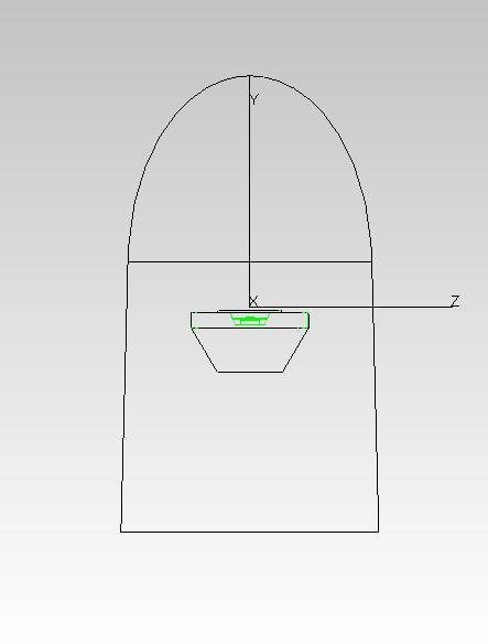
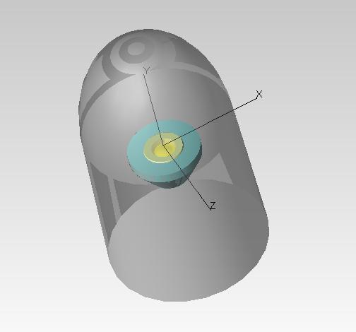
34 3D Solid Model of LED For a layered phosphor (sedimentation), we can use the side-view image to create the solid model in the TracePro Interactive Optimizer
35 3D Solid Model of LED Epoxy + Phosphor mixture (lower concentration = 1x) Reflector cup (diffuse reflective surface) Phosphor sedimentation (higher concentration = 10x) LED die


36 3D Solid Model of LED TracePro Fluorescence Property Generator Utility Color analysis (CIE, CCT, CRI) Prediction of mixed color Estimation of the thickness and concentration of the phosphor layer


37 3D Solid Model of LED
38 Source Modeling Tools in TracePro

39 Surface Source Property Generator Utility Please see our video tutorial at

40 Fluorescence Property Generator Utility

41 IES/LDT Import Utility
42 Choosing the Right Source Model
43 Point Sources and Grid Sources Best for: Planar sources that have a well defined boundary Sources that emit in a Lambertian, Gaussian, or uniform manner Monochromatic and polychromatic sources Considerations: Not the best option for a 3-dimensional source May not be able to model more complex angular distributions Examples: Fiber optics Laser diodes
44 Ray File Sources Best for: Planar and 3-dimensional sources Sources that emit in complex angular distribution patterns Sources that can be modeled monochromatically Sources that have lenses and structural elements Considerations: Defined monochromatically Not a good choice if emitted light will interact with source IES and LDT files treat the source as a point source, no position data for ray starting positions Examples: LEDs Luminaires

45 Ray File Sources Some of the light emitted by the LED is totally internally reflected by the lens Ray sorting feature in TracePro is used to show rays that are hitting the LED s lens dome Small percentage of rays shown Approximately 0.1% of initial flux is impinging back on the source
46 Surface Source Properties Best for: Detailed source models Sources that emit in complex angular and spectral distribution patterns Where modeling the interaction of light with the source structure is important Considerations: Models can be more complex to make Need accurate material and surface properties Examples: LEDs Lamps such as arc and filament Complete optical systems

47 Surface Source Property Application
48 3D Solid Model Best for: Detailed source models Sources that emit in complex angular and spectral distribution patterns Where modeling the interaction of light with the source structure is important Considerations: Models can be more complex to make Need accurate material and surface properties Examples: LEDs Lamps such as arc and filament Complete optical systems

49 3D Solid Model Application Arc is defined polychromatically Luminous intensity distribution of the arc is modeled Spectral properties can be tracked through the model, for example the dichroic filter shown here
50 Measured vs. Modeled Results

51 LED Example #1

52 LED Example #1 10mm Mobile phone picture of actual LED illuminance at a 10cm distance TracePro TrueColor Irradiance Map raytrace at a 10cm distance


53 LED Example #1

54 LED Example #2

55 LED Example #2 Mobile phone picture of actual LED illuminance at a 2.2cm distance TracePro TrueColor Irradiance Map raytrace at a 2.2cm distance

56 LED Example #2


57 Xenon Flashlamp Example TracePro model of PerkinElmer, now Excelitas, FX-1150 flashlamp


58 Xenon Flashlamp Example Actual image of FX-1150 arc TracePro model of FX-1150 arc
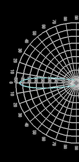
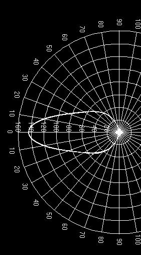
59 Xenon Flashlamp Example Dip caused by probe orthogonal to the arc Angular Distribution: Measured vs. Modeled
60 Xenon Flashlamp Example Spectral Distribution Measured (0.7nm sampling interval) Modeled (2nm sampling interval)
61 Summary Several ways to model light source Examples of options for modeling light sources were shown Best option will depend on the application Surface source properties and 3D models offer the most versatility Accurate source models depend on accurate property definitions Excellent correlation was shown between measured and modeled data for LEDs and a xenon short-arc flashlamp
62 Thank You
63 Questions and Answers
64 For Additional Information Please Contact: Lambda Research Corporation Littleton, MA
MODELING LED LIGHTING COLOR EFFECTS IN MODERN OPTICAL ANALYSIS SOFTWARE LED Professional Magazine Webinar 10/27/2015
 MODELING LED LIGHTING COLOR EFFECTS IN MODERN OPTICAL ANALYSIS SOFTWARE LED Professional Magazine Webinar 10/27/2015 Presenter Dave Jacobsen Senior Application Engineer at Lambda Research Corporation for
Design Verification and Analysis Tools in TracePro. Presented by : Lambda Research Corporation 25 Porter Rd. Littleton, MA
 Design Verification and Analysis Tools in TracePro Presented by : Lambda Research Corporation 25 Porter Rd. Littleton, MA 01460 www.lambdares.com Moderator: Andy Knight Technical Sales Manager Lambda Research
Using TracePro for LED Lighting Design Applications. Presented by : Lambda Research Corporation 25 Porter Rd. Littleton, MA
 Using TracePro for LED Lighting Design Applications Presented by : Lambda Research Corporation 25 Porter Rd. Littleton, MA 01460 www.lambdares.com Moderator: Andy Knight Technical Sales Manager Lambda
Optimizing the TracePro Optimization Process
 Optimizing the TracePro Optimization Process A TracePro Webinar December 17, 2014 Presenter Presenter Dave Jacobsen Sr. Application Engineer Lambda Research Corporation Moderator Mike Gauvin Vice President
Getting Started with TracePro. A TracePro Webinar March 2, 2016
 Getting Started with TracePro A TracePro Webinar March 2, 2016 Presenter Presenter Dave Jacobsen Sr. Application Engineer Lambda Research Corporation Moderator Mike Gauvin Vice President of Sales and Marketing
Tips, Tricks, and Shortcuts to Improve Productivity and Efficiency with TracePro
 Tips, Tricks, and Shortcuts to Improve Productivity and Efficiency with TracePro Presented by : Lambda Research Corporation 25 Porter Rd. Littleton, MA 01460 www.lambdares.com Moderator: Andy Knight Technical
Ray and Path Sorting in TracePro
 Ray and Path Sorting in TracePro A Lambda Research Corporation Webinar December 15, 2016 Presenter Presenter Dave Jacobsen Sr. Application Engineer Lambda Research Corporation Moderator Mike Gauvin Vice
Optical Reflector Design using the TracePro Interactive Optimizer
 Optical Reflector Design using the TracePro Interactive Optimizer Presented by : Lambda Research Corporation 25 Porter Rd. Littleton, MA 01460 www.lambdares.com Moderator: Andy Knight Technical Sales Manager
TracePro s Monte Carlo Raytracing Methods, reducing statistical noise, memory usage and raytrace times
 TracePro s Monte Carlo Raytracing Methods, reducing statistical noise, memory usage and raytrace times Presented by : Lambda Research Corporation 25 Porter Rd. Littleton, MA 01460 www.lambdares.com Moderator:
How to use the new TracePro Solar Utility for comprehensive solar calculations
 How to use the new TracePro Solar Utility for comprehensive solar calculations Presented by : Lambda Research Corporation 25 Porter Rd. Littleton, MA 01460 Moderators: Andy Knight Technical Sales Manager
TRACEPRO AN INTRODUCTION TO THE NEW SIMPLIFIED MENU STRUCTURE AND NEW FEATURES. July 15, 2015
 TRACEPRO 7.6 - AN INTRODUCTION TO THE NEW SIMPLIFIED MENU STRUCTURE AND NEW FEATURES July 15, 2015 Presenter Presenter Mike Gauvin Vice President of Sales and Marketing Lambda Research Corporation Moderator
Fluorescence. Requirements. Introduction. Models: FluorescenceExampleBegin.oml. Properties: FluorescenceExampleProperties.txt
 Fluorescence Requirements Models: FluorescenceExampleBegin.oml Properties: FluorescenceExampleProperties.txt Editions: TracePro Expert Introduction TracePro Expert is capable of modeling fluorescent material.
Ghost and Stray Light Analysis using TracePro. February 2012 Webinar
 Ghost and Stray Light Analysis using TracePro February 2012 Webinar Moderator: Andy Knight Technical Sales Manager Lambda Research Corporation Presenter: Michael Gauvin Vice President of Sales Lambda Research
Illumination Design, Analysis, and Optimization Software
 SUPERIOR OPTO-MECHANICAL SOFTWARE Illumination Design, Analysis, and Optimization Software TracePro is award-winning opto-mechanical software used for design, analysis, and optimization of optical and
An Introduction to the Scheme Macro Language in TracePro
 An Introduction to the Scheme Macro Language in TracePro Presented by : Lambda Research Corporation 25 Porter Rd. Littleton, MA 01460 www.lambdares.com Moderator: Andy Knight Technical Sales Manager Lambda
Optimize Structured LCD Backlight Components Accurately and Quickly
 T E C H N I C A L N O T E Optimize Structured LCD Backlight Components Accurately and Quickly With TracePro Opto-Mechanical Design Software s Textured RepTile Optimization Utility TracePro s Textured RepTile
TracePro Stray Light Simulation
 TracePro Stray Light Simulation What Is Stray Light? A more descriptive term for stray light is unwanted light. In an optical imaging system, stray light is caused by light from a bright source shining
Lightpipe. Requirements. Introduction. This example shows you how to create and analyze a lightpipe using TracePro.
 Requirements Models: None Properties: None Editions: TracePro LC, Standard and Expert Introduction In this tutorial we will be creating a curved light pipe from scratch. This example shows you how to create
Update Guide Release 7.6 Revised: 26-Feb-2015
 Update Guide Release 7.6 Revised: 26-Feb-2015 Lambda Research Corporation 25 Porter Road Littleton, MA 01460 USA Tel. (+1) 978-486-0766 support@lambdares.com Lambda Research Corporation COPYRIGHT AND
SOLUTIONS FOR IES/LDT FILE CREATION
 SOLUTIONS FOR IES/LDT FILE CREATION Presented By Austin Piehl June 20, 2017 2017 Radiant Vision Systems, LLC. All Rights Reserved. Light & Color Automated Visual Inspection Global Support TODAY S AGENDA
FRED Display Application Note
 FRED Display Application Note Most displays consist of several optical components. The most important component is the source of light that illuminates the display. All displays need a mechanism to send
TracePro Tutorial Tissue Optics
 TracePro Tutorial Tissue Optics Splitting the Screen To view the System Tree, select Window Split, then drag the mouse to the right to position the vertical splitter bar. Alternatively, you can place your
Simulation of Phosphor Converted LED Packaging with Considerations on Phosphor Settling
 Simulation of Phosphor Converted LED Packaging with Considerations on Phosphor Settling Ph. D., Kit Cheong, Breault Research Organization, USA, Tucson Abstract Settling of phosphor particles in PC-LED
TracePro Tutorial: Creating Source Files
 TracePro Tutorial: Requirements Models: None Properties: None Editions: TracePro LC, Standard or Expert Introduction A file containing ray data can be inserted into a TracePro model and used as a source.
LightTools Illumination Design Software
 LightTools Illumination Design Software Design, Analyze, Optimize and Deliver Illumination Optics synopsys.com/optical-solutions Design Highlights Design Highlights at a Glance Smart system modeling with
This tutorial illustrates how to use TracePro for the analysis of LCD Back Lights. The steps include:
 Requirements Models: None Properties: None Editions: TracePro Expert Introduction This tutorial illustrates how to use TracePro for the analysis of LCD Back Lights. The steps include: Generating a solid
LightTools Illumination Design Software. Design, Analyze, Optimize and Deliver Illumination Optics
 LightTools Illumination Design Software Design, Analyze, Optimize and Deliver Illumination Optics Design Highlights Design Highlights at a Glance ``Smart system modeling with full optical accuracy and
Textured RepTile Backlight
 Requirements Models: None Properties: None Editions: TracePro Expert Introduction There are a number of optical systems that use small, repeated optical geometry to perform. Examples include the structure
LucidShape Computer Aided Lighting Overview. Willi Brandenburg brandenburg gmbh
 LucidShape Computer Aided Lighting Overview Willi Brandenburg brandenburg gmbh www.brandenburg-gmbh.de Overview Simulation LucidFunGeo Optic design Lit Appearance Optimizer Other Street lighting 2 Simulation
Software for Opto-Mechanical Modeling. RayViz for SolidWorks User s Manual Release Revision 6/6/2017
 Software for Opto-Mechanical Modeling RayViz for SolidWorks User s Manual Release 7.8.1 Revision 6/6/2017 Lambda Research Corporation 25 Porter Road Littleton, MA 01460 Tel. 978-486-0766 FAX 978-486-0755
The Closest Thing to Working at the Speed of Light.
 Software for Opto-Mechanical Modeling The Closest Thing to Working at the Speed of Light. Lambda Research Corporation 80 Taylor Street P.O. Box 1400 8230 East Broadway, Suite E2 Littleton, MA 01460-4400
dq dt I = Irradiance or Light Intensity is Flux Φ per area A (W/m 2 ) Φ =
 Φ =") Radiometry (From Intro to Optics, Pedrotti -4) Radiometry is measurement of Emag radiation (light) Consider a small spherical source Total energy radiating from the body over some time is Q total Radiant
Radiometry (From Intro to Optics, Pedrotti -4) Radiometry is measurement of Emag radiation (light) Consider a small spherical source Total energy radiating from the body over some time is Q total Radiant
Optimization of optical systems for LED spot lights concerning the color uniformity
 Optimization of optical systems for LED spot lights concerning the color uniformity Anne Teupner* a, Krister Bergenek b, Ralph Wirth b, Juan C. Miñano a, Pablo Benítez a a Technical University of Madrid,
Ray Optics. Lecture 23. Chapter 23. Physics II. Course website:
 Lecture 23 Chapter 23 Physics II Ray Optics Course website: http://faculty.uml.edu/andriy_danylov/teaching/physicsii Let s finish talking about a diffraction grating Diffraction Grating Let s improve (more
Engineered Diffusers Intensity vs Irradiance
 Engineered Diffusers Intensity vs Irradiance Engineered Diffusers are specified by their divergence angle and intensity profile. The divergence angle usually is given as the width of the intensity distribution
LED19WPAR38/NFL/827-DIM
 LED19WPAR38/NFL/827-DIM EiKO Global, LLC Model: LED19WPAR38/NFL/827-DIM TABLE OF CONTENTS 1 - GENERAL INFORMATION... 3 1.1 PRODUCT DESCRIPTION FOR EQUIPMENT UNDER TEST (EUT)... 3 1.2 OBJECTIVE... 3 1.3
Bulb & Reflector. Opening a File
 Opening a File Open the File Menu and select the Open option. A Open file dialog box will appear. After the Open file Dialog box appears click on the file eliprefl filename with the left mouse button to
WHITE PAPER. How to Generate a Ray Set from an RSMX Source Model. Zemax A Radiant Zemax Company
 How to Generate a Ray Set from an RSMX Source Model How to Generate a Ray Set from an RSMX Source Model Introduction The most general description of a complex source is given in a Radiant Source Model
Ray Optics I. Last time, finished EM theory Looked at complex boundary problems TIR: Snell s law complex Metal mirrors: index complex
 Phys 531 Lecture 8 20 September 2005 Ray Optics I Last time, finished EM theory Looked at complex boundary problems TIR: Snell s law complex Metal mirrors: index complex Today shift gears, start applying
dq dt I = Irradiance or Light Intensity is Flux Φ per area A (W/m 2 ) Φ =
 Φ =") Radiometry (From Intro to Optics, Pedrotti -4) Radiometry is measurement of Emag radiation (light) Consider a small spherical source Total energy radiating from the body over some time is Q total Radiant
Radiometry (From Intro to Optics, Pedrotti -4) Radiometry is measurement of Emag radiation (light) Consider a small spherical source Total energy radiating from the body over some time is Q total Radiant
Supplementary Figure 1 Optimum transmissive mask design for shaping an incident light to a desired
 Supplementary Figure 1 Optimum transmissive mask design for shaping an incident light to a desired tangential form. (a) The light from the sources and scatterers in the half space (1) passes through the
E (sensor) is given by; Object Size
 is given by; Object Size") A P P L I C A T I O N N O T E S Practical Radiometry It is often necessary to estimate the response of a camera under given lighting conditions, or perhaps to estimate lighting requirements for a particular
A P P L I C A T I O N N O T E S Practical Radiometry It is often necessary to estimate the response of a camera under given lighting conditions, or perhaps to estimate lighting requirements for a particular
Reflective Illumination for DMS 803 / 505
 APPLICATION NOTE // Dr. Michael E. Becker Reflective Illumination for DMS 803 / 505 DHS, SDR, VADIS, PID & PLS The instruments of the DMS 803 / 505 series are precision goniometers for directional scanning
LED Optics Designer 1.6. User's Guide
 Limited Liability Company «LED Optics Design» 151-217, Molodogvardeyskaya str., Samara, 443001, Russian Federation Tel.: +78463322764, Fax: +78463325620 http://ledopticsdesign.com, info@ledopticsdesign.com
Modeling Custom Surface Roughness with LucidShape 2D Scatter Curve BSDF Material
 WHITE PAPER Modeling Custom Surface Roughness with LucidShape 2D Scatter Curve BSDF Material Author Andreas Bielawny, Ph.D. CAE Synopsys, Inc. Abstract LucidShape accurately simulates how light interacts
Elliptical Reflector Tutorial. 6/16/2000 TracePro Elliptical Reflector Tutorial 1
 Elliptical Reflector Tutorial 6/16/2000 TracePro Elliptical Reflector Tutorial 1 Opening the Elliptical Reflector File Open the File Menu and select the Open option. A Open file dialog box will appear.
FMT Lens Series for Cree XLamp 1 LEDs
 FMT Lens Series for Cree XLamp 1 LEDs Small bubble optic for maximum design flexibility High light efficiency Tape and Reel packaging for automated manufacturing processes Includes alignment and glue features
Anidolic Daylight Concentrator of Structural Translucent Concrete Envelope
 Berkeley Education Alliance for Research in Singapore Singapore-Berkeley Building Efficiency and Sustainability in the Tropics Anidolic Daylight Concentrator of Structural Translucent Concrete Envelope
Ray Optics. Lecture 23. Chapter 34. Physics II. Course website:
 Lecture 23 Chapter 34 Physics II Ray Optics Course website: http://faculty.uml.edu/andriy_danylov/teaching/physicsii Today we are going to discuss: Chapter 34: Section 34.1-3 Ray Optics Ray Optics Wave
Radiometry (From Intro to Optics, Pedrotti 1-4) Radiometry is measurement of Emag radiation (light) Consider a small spherical source Assume a black
 Radiometry is measurement of Emag radiation (light) Consider a small spherical source Assume a black") Radiometry (From Intro to Optics, Pedrotti -4) Radiometry is measurement of Emag radiation (light) Consider a small spherical source Assume a black body type emitter: uniform emission Total energy radiating
Radiometry (From Intro to Optics, Pedrotti -4) Radiometry is measurement of Emag radiation (light) Consider a small spherical source Assume a black body type emitter: uniform emission Total energy radiating
OVERVIEW. Photopia for SOLIDWORKS Tutorial. 3 PODT Lens Design
 OVERVIEW In this tutorial you will design a wide beam lens with a peak beam angle around 65 using the Parametric Optical Design Tools (PODT) and the CREE XP-L LED. The peak intensity value should be at
WAVELENGTH MANAGEMENT
 BEAM DIAGNOS TICS SPECIAL PRODUCTS OEM DETECTORS THZ DETECTORS PHOTO DETECTORS HIGH POWER SOLUTIONS POWER DETECTORS ENERGY DETECTORS MONITORS Camera Accessories WAVELENGTH MANAGEMENT UV CONVERTERS UV Converters
Lecture 5 Chapter 1 & 2. Sources of light
 We are here Lecture 5 Chapter 1 & 2 Some history of technology How vision works What is light Wavelength and Frequency: c = f λ Scientific notation and metric units Electromagnetic spectrum Transmission
Chapter 24. Wave Optics
 Chapter 24 Wave Optics Wave Optics The wave nature of light is needed to explain various phenomena Interference Diffraction Polarization The particle nature of light was the basis for ray (geometric) optics
FluxGage. FluxGage. LED Luminaire Measurement System User Manual
 FluxGage FluxGage LED Luminaire Measurement System User Manual 1 Acronyms... 3 2 Introduction... 4 2.1 Operation principle... 4 3 Specifications... 5 4 Mechanical and Electrical Installation... 9 4.1 Unpacking...
f. (5.3.1) So, the higher frequency means the lower wavelength. Visible part of light spectrum covers the range of wavelengths from
 So, the higher frequency means the lower wavelength. Visible part of light spectrum covers the range of wavelengths from") Lecture 5-3 Interference and Diffraction of EM Waves During our previous lectures we have been talking about electromagnetic (EM) waves. As we know, harmonic waves of any type represent periodic process
Lecture 5-3 Interference and Diffraction of EM Waves During our previous lectures we have been talking about electromagnetic (EM) waves. As we know, harmonic waves of any type represent periodic process
PHYSICS 213 PRACTICE EXAM 3*
 PHYSICS 213 PRACTICE EXAM 3* *The actual exam will contain EIGHT multiple choice quiz-type questions covering concepts from lecture (16 points), ONE essay-type question covering an important fundamental
Council for Optical Radiation Measurements (CORM) 2016 Annual Technical Conference May 15 18, 2016, Gaithersburg, MD
 2016 Annual Technical Conference May 15 18, 2016, Gaithersburg, MD") Council for Optical Radiation Measurements (CORM) 2016 Annual Technical Conference May 15 18, 2016, Gaithersburg, MD Multispectral measurements of emissive and reflective properties of displays: Application
Council for Optical Radiation Measurements (CORM) 2016 Annual Technical Conference May 15 18, 2016, Gaithersburg, MD Multispectral measurements of emissive and reflective properties of displays: Application
WAVELENGTH MANAGEMENT
 Camera Accessories WAVELENGTH MANAGEMENT UV CONVERTERS UV Converters take advantage of a phenomenon called fluorescence to extend the performance range of the Beamage beam profiling camera to ultraviolet
OPSE FINAL EXAM Fall CLOSED BOOK. Two pages (front/back of both pages) of equations are allowed.
 of equations are allowed.") CLOSED BOOK. Two pages (front/back of both pages) of equations are allowed. YOU MUST SHOW YOUR WORK. ANSWERS THAT ARE NOT JUSTIFIED WILL BE GIVEN ZERO CREDIT. ALL NUMERICAL ANSERS MUST HAVE UNITS INDICATED.
CLOSED BOOK. Two pages (front/back of both pages) of equations are allowed. YOU MUST SHOW YOUR WORK. ANSWERS THAT ARE NOT JUSTIFIED WILL BE GIVEN ZERO CREDIT. ALL NUMERICAL ANSERS MUST HAVE UNITS INDICATED.
Feature Map. Work the way you want, faster, easier... with the same Zemax reliability. RIBBONS / EDITORS
 Feature Map Feature Map Work the way you want, faster, easier... with the same Zemax reliability. Zemax brings a new level of productivity to optics simulation software with OpticStudio14. Built on Zemax
FLT Lens Series for LG Innotek 3535 Ceramic 1 LEDs
 FLT Lens Series for LG Innotek 3535 Ceramic 1 LEDs High efficiency Available in 3 different beams Easy assembly The FLT lens series offers three lenses specifically designed for the 3535 Ceramic LEDs from
Physics 202, Lecture 23
 Physics 202, Lecture 23 Today s Topics Lights and Laws of Geometric Optics Nature of Light Reflection and Refraction Law of Reflection Law of Refraction Index of Reflection, Snell s Law Total Internal
Single Slit Diffraction
 Name: Date: PC1142 Physics II Single Slit Diffraction 5 Laboratory Worksheet Part A: Qualitative Observation of Single Slit Diffraction Pattern L = a 2y 0.20 mm 0.02 mm Data Table 1 Question A-1: Describe
2/26/2016. Chapter 23 Ray Optics. Chapter 23 Preview. Chapter 23 Preview
 Chapter 23 Ray Optics Chapter Goal: To understand and apply the ray model of light. Slide 23-2 Chapter 23 Preview Slide 23-3 Chapter 23 Preview Slide 23-4 1 Chapter 23 Preview Slide 23-5 Chapter 23 Preview
FCM SERIES LENSES. for SEOUL SEMICO NDUCTOR Z-POWER P5 TM LEDs. Highly efficient color mixing lens Available in 3 different beams
 FCM SERIES LENSES for SEOUL SEMICO NDUCTOR Z-POWER P5 TM LEDs Highly efficient color mixing lens Available in 3 different beams The FCM lens series is a range of four lenses specifically designed for the
Imaging Sphere Measurement of Luminous Intensity, View Angle, and Scatter Distribution Functions
 Imaging Sphere Measurement of Luminous Intensity, View Angle, and Scatter Distribution Functions Hubert Kostal, Vice President of Sales and Marketing Radiant Imaging, Inc. 22908 NE Alder Crest Drive, Suite
FLP Lens series for LG Innotek LEMWW35 1 LEDs
 FLP Lens series for LG Innotek LEMWW35 1 LEDs High efficiency Available in 5 different beam profiles Easy assembly The FLP lens offers five low-profile lenses specifically designed for the LEMWW35 LEDs
How to Use the Luminit LSD Scatter Model
 How to Use the Luminit LSD Scatter Model Summary: This article describes the characteristics and use of Luminit s LSD scatter model in OpticStudio. The scatter model presented here is the idealized scatter
1.Rayleigh and Mie scattering. 2.Phase functions. 4.Single and multiple scattering
 5 November 2014 Outline 1.Rayleigh and Mie scattering 2.Phase functions 3.Extinction 4.Single and multiple scattering Luca Lelli luca@iup.physik.uni-bremen.de Room U2080 Phone 0421.218.62097 Scattering
FLT Lens Series for Cree XLamp 1 LEDs
 FLT Lens Series for Cree XLamp 1 LEDs High efficiency Available in 3 different beams Easy assembly The FLT lens series offers three lenses specifically designed for XB-D, XP-E, XP-G, XP- G2 and XT-E XLamp
Light. Electromagnetic wave with wave-like nature Refraction Interference Diffraction
 Light Electromagnetic wave with wave-like nature Refraction Interference Diffraction Light Electromagnetic wave with wave-like nature Refraction Interference Diffraction Photons with particle-like nature
TracePro Tutorial LED Example
 TracePro Tutorial LED Example LED Example Create an LED package based on manufacturer s datasheet. Use Siemens LWT676 Data include dimensions and photometric curve TracePro LED Tutorial 2 First we analyze
Optics Vac Work MT 2008
 Optics Vac Work MT 2008 1. Explain what is meant by the Fraunhofer condition for diffraction. [4] An aperture lies in the plane z = 0 and has amplitude transmission function T(y) independent of x. It is
2011 Optical Science & Engineering PhD Qualifying Examination Optical Sciences Track: Advanced Optics Time allowed: 90 minutes
 2011 Optical Science & Engineering PhD Qualifying Examination Optical Sciences Track: Advanced Optics Time allowed: 90 minutes Answer all four questions. All questions count equally. 3(a) A linearly polarized
NEAR FIELD GONIOMETRIC SYSTEMS FOR SOLID STATE LIGHTING: LUMINANCE, INTENSITY, COLOR, AND
 NEAR FIELD GONIOMETRIC SYSTEMS FOR SOLID STATE LIGHTING: LUMINANCE, INTENSITY, COLOR, AND SPECTRA AS A FUNCTION OF ANGLE Douglas Kreysar Chief Operating Officer Presentation Outline What is a Near Field
Harold Brunt Optomechanical Designer, Corporate Officer, VP LumenFlow Corp. Board Member, United Lumen, LLC
 6/22/2017 1 Harold Brunt Optomechanical Designer, Corporate Officer, VP LumenFlow Corp. Board Member, United Lumen, LLC LumenFlow Corp. is a Photonics Engineering, Consulting and small manufacturing company
Design and evaluation of an LED-based light fixture
 Design and evaluation of an LED-based light fixture Yimin Gu and Nadarajah Narendran Lighting Research Center Rensselaer Polytechnic Institute, Troy, NY 12180 www.lrc.rpi.edu Gu, Y., and N. Narendran.
Agilent Cary Universal Measurement Spectrophotometer (UMS)
") Agilent Cary Universal Measurement Spectrophotometer (UMS) See what you ve been missing Date: 13 th May 2013 TRAVIS BURT UV-VIS-NIR PRODUCT MANAGER AGILENT TECHNOLOGIES 1 Agenda Introducing the Cary 7000
Agilent Cary Universal Measurement Spectrophotometer (UMS) See what you ve been missing Date: 13 th May 2013 TRAVIS BURT UV-VIS-NIR PRODUCT MANAGER AGILENT TECHNOLOGIES 1 Agenda Introducing the Cary 7000
FCM-series Lenses for Luminus Devices SST-50 and SST-90 LEDs
 FCM-series Lenses for Luminus Devices SST-50 and SST-90 LEDs Highly efficient TIR collimation lenses Homogeneous beam Bright central spot with minimal halo The FCM-series lenses are specifically designed
Bridgelux ES Star Array Series
 Bridgelux ES Star Array Series Product Data Sheet DS23 PRELIMINARY, Expires 12/15/11 BXRA-27x0540, BXRA-27x0740, BXRA-30x0540, BXRA-30x0740, BXRA-40E0810, BXRA-56C0700, BXRA-56C1000 Introduction The Bridgelux
AP* Optics Free Response Questions
 AP* Optics Free Response Questions 1978 Q5 MIRRORS An object 6 centimeters high is placed 30 centimeters from a concave mirror of focal length 10 centimeters as shown above. (a) On the diagram above, locate
X-Ray fluorescence and Raman spectroscopy
 X-Ray fluorescence and Raman spectroscopy Advanced physics laboratory (nd part) 4CFU Catalini Letizia, De Angelis Giulia Vittoria, Piselli Verdiana Abstract In this paper we report about two different
Bridgelux Vero 18 Array Series
 Bridgelux Vero 18 Array Series Product Data Sheet DS32 Published July 18 th 2013 BXRC-27x4000, BXRC-30x4000, BXRC-35E4000, BXRC-40E4000, BXRC-50C4000 Introduction Vero TM represents a revolutionary advancement
Towards a robust model of planetary thermal profiles
 Towards a robust model of planetary thermal profiles RT Equation: General Solution: RT Equation: General Solution: Extinction coefficient Emission coefficient How would you express the Source function
Computer modeling of LED light pipe systems for uniform display illumination
 Computer modeling of LED light pipe systems for uniform display illumination John F. Van Derlofske Lighting Research Center Rensselaer Polytechnic Institute, Troy, NY 12180 www.lrc.rpi.edu Copyright 2001
LucidShape Procedural Surfaces for Lens and Reflector Applications
 WHITE PAPER LucidShape Procedural Surfaces for Lens and Reflector Applications Paper #006-2 Author Peter Sommer Synopsys Abstract State-of-the-art lighting systems in motor vehicles require new geometries
Announcements. Lighting. Camera s sensor. HW1 has been posted See links on web page for readings on color. Intro Computer Vision.
 Announcements HW1 has been posted See links on web page for readings on color. Introduction to Computer Vision CSE 152 Lecture 6 Deviations from the lens model Deviations from this ideal are aberrations
Physics 214 Midterm Fall 2003 Form A
 1. A ray of light is incident at the center of the flat circular surface of a hemispherical glass object as shown in the figure. The refracted ray A. emerges from the glass bent at an angle θ 2 with respect
Experiment 8 Wave Optics
 Physics 263 Experiment 8 Wave Optics In this laboratory, we will perform two experiments on wave optics. 1 Double Slit Interference In two-slit interference, light falls on an opaque screen with two closely
Advanced Tutorial Designing a Medium Flood Beam with an LED Source
 Advanced Tutorial Designing a Medium Flood Beam with an LED Source This tutorial demonstrates designing a reflector around an LED to create a medium flood beam, and using an anisotropic material. It is
Advanced Tutorial Designing a Linear Fluorescent Reflector with the Parametric Optical Design Tools
 Advanced Tutorial Designing a Linear Fluorescent Reflector with the Parametric Optical Design Tools Prerequisites This tutorial is written with the assumption that you have already completed and understand
UV curing of high-value, 3-D
 Computer Simulation of 3-D UV Curing of Automotive Clearcoats By Kevin Joesel UV curing of high-value, 3-D shapes, such as car bodies, presents considerable challenges. Successful UV-curing polymerization
Illumination and Shading - II
 Illumination and Shading - II Computer Graphics COMP 770 (236) Spring 2007 Instructor: Brandon Lloyd 2/19/07 1 From last time Light Sources Empirical Illumination Shading Local vs Global Illumination 2/19/07
Chapter 37. Wave Optics
 Chapter 37 Wave Optics Wave Optics Wave optics is a study concerned with phenomena that cannot be adequately explained by geometric (ray) optics. Sometimes called physical optics These phenomena include:
Light Tec Scattering measurements guideline
 Light Tec Scattering measurements guideline 1 Our Laboratory Light Tec is equipped with a Photometric Laboratory (a dark room) including: Goniophotometers: REFLET 180S. High specular bench (10 meters),
Light Tec Scattering measurements guideline
 Light Tec Scattering measurements guideline 1 Our Laboratory Light Tec is equipped with a Photometric Laboratory (a dark room) including: Goniophotometers: REFLET 180S. High specular bench (10 meters),
Optics Part 1. Vern Lindberg. March 5, 2013
 Optics Part 1 Vern Lindberg March 5, 2013 This section of the course deals with geometrical optics refraction, reflection, mirrors, lenses, and aberrations. Physical optics, interference, diffraction,
The Rendering Equation. Computer Graphics CMU /15-662
 The Rendering Equation Computer Graphics CMU 15-462/15-662 Review: What is radiance? Radiance at point p in direction N is radiant energy ( #hits ) per unit time, per solid angle, per unit area perpendicular
Lecture 4 Recap of PHYS110-1 lecture Physical Optics - 4 lectures EM spectrum and colour Light sources Interference and diffraction Polarization
 Lecture 4 Recap of PHYS110-1 lecture Physical Optics - 4 lectures EM spectrum and colour Light sources Interference and diffraction Polarization Lens Aberrations - 3 lectures Spherical aberrations Coma,