Imaging Sphere Measurement of Luminous Intensity, View Angle, and Scatter Distribution Functions
|
|
|
- Bernadette Shepherd
- 6 years ago
- Views:
Transcription


1 Imaging Sphere Measurement of Luminous Intensity, View Angle, and Scatter Distribution Functions Hubert Kostal, Vice President of Sales and Marketing Radiant Imaging, Inc NE Alder Crest Drive, Suite 100 Redmond, WA


2 Overview Imaging Sphere Theory Brief Description Luminous Intensity Distribution Measurement View Angle Performance Measurement BSDF (Scatter) Measurement System Function and Assessment vs. Traditional Measurement Methods 2
3 IMAGING SPHERE THEORY 3
 is placed a geometric center of sphere Convex mirror placed to one side of DUT acts as a")
4 Imaging Sphere Design and Theory (1) MEASUREMENT METHOD Imaging sphere is a hemisphere. For luminous intensity distribution and view angle performance measurement, the DUT (light source or display) is placed a geometric center of sphere Convex mirror placed to one side of DUT acts as a fisheye lens The imaging photometer/radiometer/colorimeter captures an image of the entire inner surface of the sphere (2π steradians) in a single measurement 4


 or a narrowband")
5 Imaging Sphere Design and Theory (2a) ILLUMINATION METHOD For BRDF measurement, a probe beam illuminates the material sample placed at the Imaging Sphere aperture The angle of incidence of the probe beam can be adjusted from 0 to 180 degrees The probe beam can be a broadband light source (e.g., metal halide or tungsten halogen) or a narrowband source (e.g., laser or a narrowband selected by a monochromator) 5
6 Imaging Sphere Design and Theory (2b) SCATTER MEASUREMENT The light scatter off of the material illuminates the interior of the Imaging Sphere dome The imaging colorimeter captures the light distribution Using a 1024x1024 pixel resolution, full-frame, imaging colorimeter results in seamless web of over 750,000 simultaneous luminance and color measurements Typical measurement time is a few seconds for photopic and about 10 seconds for color measurement; times will vary based on the material 6
 for BRDF (and BTDF) measurement Probe beam For illumination; can be a wideband or narrowband source.")
7 Anatomy of the Imaging Sphere Material to be tested is placed at the aperture for BRDF and BTDF measurement Goniometric platform Can be set to any illumination angle 0 to 80 (and 110 to 180 degrees with Transmission Arm attachment) for BRDF (and BTDF) measurement Probe beam For illumination; can be a wideband or narrowband source. Convex mirror is imaged by the colorimeter Imaging sphere 500mm diameter dome with approximately 20% diffuse reflectance interior coating Imaging Colorimeter: Radiometric response ( nm) CIE photopic response V( ) CIE tristimulus response (XYZ) 7
8 LUMINOUS INTENSITY DISTRIBUTION MEASUREMENT 8


9 Imaging Sphere Luminous Intensity Measurement 9
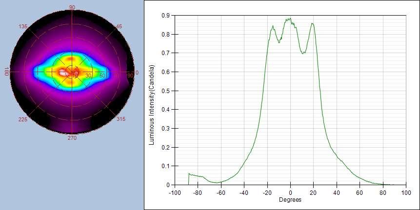
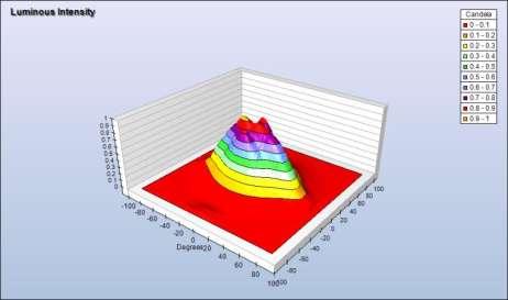
10 Measurement example Green LED 10
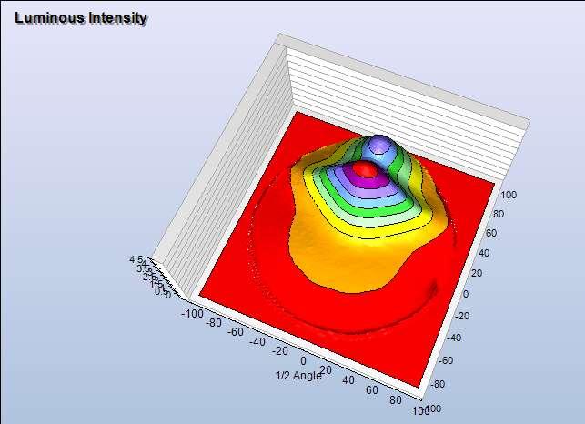
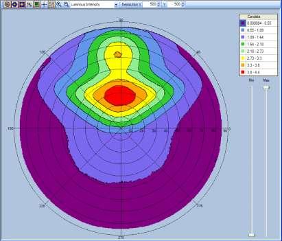
11 Measurement example Defective Blue LED 11

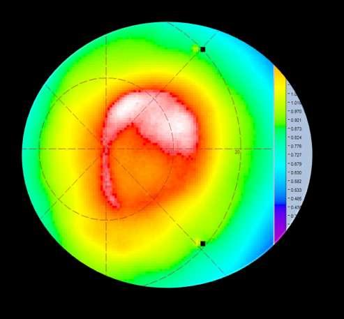
12 IS-LI blue LED scan 12

![Goniometer [near-field]](/docs-images/72/67593558/images/13-3.jpg "measurement Imaging sphere")
13 Comparison: SIG and IS-LI Measurements Source Imaging Goniometer [near-field] measurement Imaging sphere [far-field] measurement 13
14 Normalized Intensity Normalized Intensity Additional comparisons show IS accuracy Luxeon model LXHL-LW5C LED was scanned in a Radiant Imaging SIG300 for reference purposes. Subsequently, it was measured with the IS-LI. Intensity data was exported from IS-LI for this measurement for each 1 degree step in inclination and azimuth with a 2 degree virtual detector. These data were compared with the same information from the SIG 300. LXHL-LW5C IS vs SIG Vertical Cross Section LXHL-LW5C IS vs SIG Horizontal Cross Section IS SIG IS SIG Inclination (degrees) Inclination (degrees) Beam Pattern Width IS SIG300 FWHM (degrees)

15 VIEW ANGLE PERFORMANCE MEASUREMENT 15


16 Imaging Sphere View Angle Performance Measurement Black State of LDC TV 16
17 17 TN Monitor horizontal luminance cross section White Luminance (Horiz) Goniometer Conoscope Imaging Imagine Sphere
18 32 inch SPVA TV horizontal luminance cross-section White Luminance (Horiz) er Goniometer Conoscope Imaging Imagine Sphere Sphere

19 Measurement of 42 3D display 19

20 SCATTER AND APPEARANCE MEASUREMENT 20


21 IS-SA: Scatter and Appearance Measurement Quantitative measurement and characterization of surface appearance, roughness, color, translucence, total reflection and transmission, and bi-directional scatter distribution function (BRDF, BTDF) 21 21
 Material sample can be positioned relative to plane of illumination (for")
 Scatter as a function of angle - bidirectional scatter distribution function (BSDF) BSDF = BRDF + BTDF (R = Reflectance; T =")
22 Imaging Sphere Scatter Measurement A full hemisphere of luminance and color BSDF data is captured in a single measurement The illuminating angle for BRDF and BTDF measurement can be automatically adjusted (and scanned) Material sample can be positioned relative to plane of illumination (for measurement of anisotropic materials) Allows selection of illuminating light source and wavelength Total reflectance - the total integrated scatter (TIS) Scatter as a function of angle - bidirectional scatter distribution function (BSDF) BSDF = BRDF + BTDF (R = Reflectance; T = Transmission) 22


23 Imaging Sphere Measurement Example BRDF of a metal surface as a function of angle True Color Image False Color Image 23

 as a")
24 Imaging Sphere Measurement Example BRDF of a grating (Compact Disk) as a function of angle 24

 True Color")
25 Imaging Sphere Measurement Example BRDF of color changing paint False Color View (BRDF) True Color View 25
 Holographic films Metals Plastics Textiles Glass Papers Painted surfaces Polished surfaces Human skin and hair And more Example: Rendering Uniform +")
26 Imaging Sphere Measurements The Imaging Sphere has been successfully used for BSDF measurement of: Films (BEF, anti-reflection, etc.) Holographic films Metals Plastics Textiles Glass Papers Painted surfaces Polished surfaces Human skin and hair And more Example: Rendering Uniform + Environmental Lighting 26

27 CONCLUSIONS Radiant Imaging - Proprietary Information 27


28 Imaging Spheres: Variations on a Theme Imaging Sphere for Scatter and Appearance Measurement Portable Imaging Sphere Imaging Sphere for Luminous Intensity Distribution and View Angle Performance Measurement With Transmission Arm Attachment 28 28
29 Summary The Imaging Sphere is a rapid, efficient way to measure: Luminous intensity distributions for small light sources Local view angle performance for displays BRDF, BTDF and TIS for arbitrary materials Testing to date has shown excellent accuracy when compared to traditional measurement technologies Careful calibrations provide very good absolute accuracy in measurements Repeatability allows ready determination of fine scale differences between DUTs / samples New spectral measurement capabilities are currently being added to the Imaging Sphere design 29
30 References R. Rykowski, D. Kreysar, and S. Wadman, The Use of an Imaging Sphere for High-Throughput Measurements of Display Performance Technical Challenges and Mathematical Solutions, SID Symposium Digest of Technical Papers, June 2006, pp R. Rykowski, K. Chittim & S. Wadman, Imaging Sphere, Photonics Spectra, September 2005,pp S. Wadman & S. Baumer, Characterisation of Appearance by a Parousiameter, Annual Proceedings SPIE, Vol. 48, August R. Rykowski and H. Kostal, Novel Approach for LED Luminous Intensity Measurement, SPIE Photonics West, January R. Rykowski and J. Lee, Novel Technology for View Angle Performance Measurement, IMID/IDMC/Asia Display 2008 Digest, October H. Kostal, D. Kreysar, and R. Rykowski, Application of Imaging Sphere for BSDF Measurements of Arbitrary Materials, OSA Frontiers in Optics Conference, October

31 Hubert Kostal, Vice President of Sales and Marketing Radiant Imaging, Inc NE Alder Crest Drive, Suite 100 Redmond, WA
WHITE PAPER. Application of Imaging Sphere for BSDF Measurements of Arbitrary Materials
 Application of Imaging Sphere for BSDF Measurements of Arbitrary Materials Application of Imaging Sphere for BSDF Measurements of Arbitrary Materials Abstract BSDF measurements are broadly applicable to
Reflective Illumination for DMS 803 / 505
 APPLICATION NOTE // Dr. Michael E. Becker Reflective Illumination for DMS 803 / 505 DHS, SDR, VADIS, PID & PLS The instruments of the DMS 803 / 505 series are precision goniometers for directional scanning
Scattering measurements. Guidelines for measurements service
 Scattering measurements Guidelines for measurements service 1 Content Introduction Light Tec Presentation Instruments availalable. Scattering measurements Refelctors Diffusers Colors issuses Volume Scattering
Mu lt i s p e c t r a l
 Viewing Angle Analyser Revolutionary system for full spectral and polarization measurement in the entire viewing angle EZContrastMS80 & EZContrastMS88 ADVANCED LIGHT ANALYSIS by Field iris Fourier plane
Light Tec Scattering measurements guideline
 Light Tec Scattering measurements guideline 1 Our Laboratory Light Tec is equipped with a Photometric Laboratory (a dark room) including: Goniophotometers: REFLET180s. High specular bench (10 meters),
New Scatterometer for Spatial Distribution Measurements of Light Scattering from Materials
 10.2478/v10048-012-0012-y MEASUREMENT SCIENCE REVIEW, Volume 12, No. 2, 2012 New Scatterometer for Spatial Distribution Measurements of Light Scattering from Materials 1,3 E. Kawate, 1,2 M. Hain 1 AIST,
Light Tec Scattering measurements guideline
 Light Tec Scattering measurements guideline 1 Our Laboratory Light Tec is equipped with a Photometric Laboratory (a dark room) including: Goniophotometers: REFLET 180S. High specular bench (10 meters),
NEAR FIELD GONIOMETRIC SYSTEMS FOR SOLID STATE LIGHTING: LUMINANCE, INTENSITY, COLOR, AND
 NEAR FIELD GONIOMETRIC SYSTEMS FOR SOLID STATE LIGHTING: LUMINANCE, INTENSITY, COLOR, AND SPECTRA AS A FUNCTION OF ANGLE Douglas Kreysar Chief Operating Officer Presentation Outline What is a Near Field
Light Tec Scattering measurements guideline
 Light Tec Scattering measurements guideline 1 Our Laboratory Light Tec is equipped with a Photometric Laboratory (a dark room) including: Goniophotometers: REFLET 180S. High specular bench (10 meters),
Light Tec Scattering measurements guideline
 Light Tec Scattering measurements guideline 1 2 Light Tec Locations REFLET assembling plant, Aix-en-Provence, France Light Tec GmbH, Munich, Germany German office Light Tec Sarl, Hyères, France Main office
Light Tec. Characterization of ultra-polished surfaces in UV and IR. ICSO October 2016 Biarritz, France
 ICSO 2016 17-21 October 2016 Biarritz, France Light Tec Characterization of ultra-polished surfaces in UV and IR Quentin Kuperman, Author, Technical Manager Yan Cornil, Presenter, CEO Workshop 2016, 12/09
APPLICATION NOTE. New approach for directional analysis of scattered light
 APPLICATION NOTE \\ Dr. Martin Wolf, Dr. Michael E. Becker New approach for directional analysis of scattered light This application note describes how the bidirectional scattering distribution function
Scan reality...unleash your creativity
 Scan reality......unleash your creativity ANSYS OPTIS provides precise photometric & colorimetric measurements & generate libraries that characterize any material and light source. www.optis-world.com
Council for Optical Radiation Measurements (CORM) 2016 Annual Technical Conference May 15 18, 2016, Gaithersburg, MD
 2016 Annual Technical Conference May 15 18, 2016, Gaithersburg, MD") Council for Optical Radiation Measurements (CORM) 2016 Annual Technical Conference May 15 18, 2016, Gaithersburg, MD Multispectral measurements of emissive and reflective properties of displays: Application
Council for Optical Radiation Measurements (CORM) 2016 Annual Technical Conference May 15 18, 2016, Gaithersburg, MD Multispectral measurements of emissive and reflective properties of displays: Application
MODELING LED LIGHTING COLOR EFFECTS IN MODERN OPTICAL ANALYSIS SOFTWARE LED Professional Magazine Webinar 10/27/2015
 MODELING LED LIGHTING COLOR EFFECTS IN MODERN OPTICAL ANALYSIS SOFTWARE LED Professional Magazine Webinar 10/27/2015 Presenter Dave Jacobsen Senior Application Engineer at Lambda Research Corporation for
Engineered Diffusers Intensity vs Irradiance
 Engineered Diffusers Intensity vs Irradiance Engineered Diffusers are specified by their divergence angle and intensity profile. The divergence angle usually is given as the width of the intensity distribution
DMS 201 FEATURES LOW-COST MANUAL GONIOMETER SYSTEM
 light measurement DMS 201 LOW-COST MANUAL GONIOMETER SYSTEM Turnkey solution for electrooptical display characterization for quality control, research and development. FEATURES Measurement and evaluation
CSE 167: Introduction to Computer Graphics Lecture #6: Colors. Jürgen P. Schulze, Ph.D. University of California, San Diego Fall Quarter 2013
 CSE 167: Introduction to Computer Graphics Lecture #6: Colors Jürgen P. Schulze, Ph.D. University of California, San Diego Fall Quarter 2013 Announcements Homework project #3 due this Friday, October 18
Validation of the Gonioreflectometer
 Validation of the Gonioreflectometer Hongsong Li Kenneth E. Torrance PCG-03-2 May 21, 2003 i Abstract This report describes a series of experiments conducted in the Light Measurement Laboratory of the
UWE has obtained warranties from all depositors as to their title in the material deposited and as to their right to deposit such material.
 Sohaib, A., Farooq, A., Smith, L., Smith, M. and Broadbent, L. () BRDF of human skin in the visible spectrum., (). pp. 0-. ISSN 00- Available from: http://eprints.uwe.ac.uk/ We recommend you cite the published
CSE 167: Lecture #7: Color and Shading. Jürgen P. Schulze, Ph.D. University of California, San Diego Fall Quarter 2011
 CSE 167: Introduction to Computer Graphics Lecture #7: Color and Shading Jürgen P. Schulze, Ph.D. University of California, San Diego Fall Quarter 2011 Announcements Homework project #3 due this Friday,
The Council for Optical Radiation Measurements (CORM), NIST July 30 - Aug 1, 2018
, NIST July 30 - Aug 1, 2018") Study of the optical properties of black materials at solar reflective wavelengths in support of instrument development and satellite sensor calibration 1Jinan Zeng, 2 Nathan Kelley, 3 James J. Butler,
Study of the optical properties of black materials at solar reflective wavelengths in support of instrument development and satellite sensor calibration 1Jinan Zeng, 2 Nathan Kelley, 3 James J. Butler,
ENHANCEMENT OF DIFFUSERS BRDF ACCURACY
 ENHANCEMENT OF DIFFUSERS BRDF ACCURACY Grégory Bazalgette Courrèges-Lacoste (1), Hedser van Brug (1) and Gerard Otter (1) (1) TNO Science and Industry, Opto-Mechanical Instrumentation Space, P.O.Box 155,
MEASURING THE COLOR OF A PAINT ON CANVAS DIRECTLY WITH EXTERNAL DIFFUSE REFLECTANCE USING THE AGILENT CARY 60 UV-VIS SPECTROPHOTOMETER
 MATERIALS ANALYSIS MEASURING THE COLOR OF A PAINT ON CANVAS DIRECTLY WITH EXTERNAL DIFFUSE REFLECTANCE USING THE AGILENT CARY 60 UV-VIS SPECTROPHOTOMETER Solutions for Your Analytical Business Markets
The Rendering Equation. Computer Graphics CMU /15-662
 The Rendering Equation Computer Graphics CMU 15-462/15-662 Review: What is radiance? Radiance at point p in direction N is radiant energy ( #hits ) per unit time, per solid angle, per unit area perpendicular
Ghost and Stray Light Analysis using TracePro. February 2012 Webinar
 Ghost and Stray Light Analysis using TracePro February 2012 Webinar Moderator: Andy Knight Technical Sales Manager Lambda Research Corporation Presenter: Michael Gauvin Vice President of Sales Lambda Research
DMS 803 FEATURES OPTIONS GONIOMETER SYSTEM FOR COMPLETE DISPLAY CHARACTERIZATION
 GONIOMETER SYSTEM FOR COMPLETE DISPLAY CHARACTERIZATION Turnkey solution with motorized scanning for detailed electro-optical display characterization for quality control, research and development. FEATURES
Integrating Sphere Uniform Light Source Applications
 Integrating Sphere Uniform Light Source Applications Leadership in Reflectance Technology T E C H G U I D E TABLE OF CONTENTS 1.0 Applications...3 1.1 Focal-Plane Arrays...3 1.2 Imagers...4 1.3 Sensitometry...4
Photobiological Measurement Per IEC Solutions Overview. Gooch and Housego (Orlando)
") Photobiological Measurement Per IEC 62471 Solutions Overview Gooch and Housego (Orlando) IEC 62471 Photobiological Safety of Lamps and Lamp Systems Objectives include evaluation and control of optical
Photobiological Measurement Per IEC 62471 Solutions Overview Gooch and Housego (Orlando) IEC 62471 Photobiological Safety of Lamps and Lamp Systems Objectives include evaluation and control of optical
Radiometry & BRDFs CS295, Spring 2017 Shuang Zhao
 Radiometry & BRDFs CS295, Spring 2017 Shuang Zhao Computer Science Department University of California, Irvine CS295, Spring 2017 Shuang Zhao 1 Today s Lecture Radiometry Physics of light BRDFs How materials
Optical Scattering. Analysis. Measurement and SPIE PRESS. John C. Stover THIRD EDITION. Bellingham, Washington USA
 Optical Scattering Measurement and Analysis THIRD EDITION John C. Stover SPIE PRESS Bellingham, Washington USA Contents Preface to the First Edition xiii Preface to the Second Edition xv Acknowledgments
BLACKOUT FLEX BB TECHNICAL DATA SHEET » ARTICLE CODE» WIDTH» LENGTH» WEIGHT » COMPOSITION » FLAME RESISTANCE » AVAILABLE COLOURS.
 BLACKOUT FLEX BB TECHNICAL DATA SHEET March 2018 Blackout Flex BB is the perfect blackout fabric to combine with AV Drop or Print Frame Profiles by ShowTex. It s black backing prevents visible bracing
Mode-Field Diameter and Spot Size Measurements of Lensed and Tapered Specialty Fibers
 Mode-Field Diameter and Spot Size Measurements of Lensed and Tapered Specialty Fibers By Jeffrey L. Guttman, Ph.D., Director of Engineering, Ophir-Spiricon Abstract: The Mode-Field Diameter (MFD) and spot
Estimation of Reflection Properties of Silk Textile with Multi-band Camera
 Estimation of Reflection Properties of Silk Textile with Multi-band Camera Kosuke MOCHIZUKI*, Norihiro TANAKA**, Hideaki MORIKAWA* *Graduate School of Shinshu University, 12st116a@shinshu-u.ac.jp ** Faculty
Ray Optics. Lecture 23. Chapter 34. Physics II. Course website:
 Lecture 23 Chapter 34 Physics II Ray Optics Course website: http://faculty.uml.edu/andriy_danylov/teaching/physicsii Today we are going to discuss: Chapter 34: Section 34.1-3 Ray Optics Ray Optics Wave
782 Schedule & Notes
 782 Schedule & Notes Tentative schedule - subject to change at a moment s notice. This is only a guide and not meant to be a strict schedule of how fast the material will be taught. The order of material
m e a s u r e m e n t
 Viewing Co n e m e a s u r e m e n t The world leader for Fourier optics viewing angle instruments For Luminance, Chromaticity, Radiance & Polarization EZLite, EZContrastL80, EZContrastL80W, EZContrastXL88
IMAGING SPECTROMETER DATA CORRECTION
 S E S 2 0 0 5 Scientific Conference SPACE, ECOLOGY, SAFETY with International Participation 10 13 June 2005, Varna, Bulgaria IMAGING SPECTROMETER DATA CORRECTION Valentin Atanassov, Georgi Jelev, Lubomira
BRDF measurement and color appearance simulation based on iccmax framework
 BRDF measurement and color appearance simulation based on iccmax framework Wei-Chun HUNG, Pei-Li SUN 2017/06/28 Graduate Institute of Color and Illumination Tech., Nat. Taiwan Univ. of Sci. & Tech. Page
Accurate LED Source Modeling using TracePro
 Accurate LED Source Modeling using TracePro Presented by : Lambda Research Corporation 25 Porter Rd. Littleton, MA 01460 Moderator: Mike Gauvin Vice President of Sales and Marketing Lambda Research Corporation
Understanding Variability
 Understanding Variability Why so different? Light and Optics Pinhole camera model Perspective projection Thin lens model Fundamental equation Distortion: spherical & chromatic aberration, radial distortion
Optimization of Display-Systems
 Optimization of Display-Systems with respect to Glare, Distinctness of Image and Sparkle www.photodon.com Michael E. Becker Display-Messtechnik&Systeme - Rottenburg am Neckar display-messtechnik.de Optimization
FRESNEL LENS DIMENSIONS USING 3D PROFILOMETRY
 FRESNEL LENS DIMENSIONS USING 3D PROFILOMETRY Prepared by Duanjie Li & Benjamin Mell 6 Morgan, Ste156, Irvine CA 92618 P: 949.461.9292 F: 949.461.9232 nanovea.com Today's standard for tomorrow's materials.
Wat is licht, wat is meten? Belgisch Perspectief! Spectraal of niet-spectraal meten: that s the question
 Wat is licht, wat is meten? Belgisch Perspectief! Spectraal of niet-spectraal meten: that s the question IGOV kenniscafé Arnhem, 31 oktober 2013 Peter Hanselaer Light&Lighting Laboratory Introduction Spectral
02 Shading and Frames. Steve Marschner CS5625 Spring 2016
 02 Shading and Frames Steve Marschner CS5625 Spring 2016 Light reflection physics Radiometry redux Power Intensity power per unit solid angle Irradiance power per unit area Radiance power per unit (solid
Computer Graphics (CS 4731) Lecture 16: Lighting, Shading and Materials (Part 1)
 Lecture 16: Lighting, Shading and Materials (Part 1)") Computer Graphics (CS 4731) Lecture 16: Lighting, Shading and Materials (Part 1) Prof Emmanuel Agu Computer Science Dept. Worcester Polytechnic Institute (WPI) Why do we need Lighting & shading? Sphere
Computer Graphics (CS 4731) Lecture 16: Lighting, Shading and Materials (Part 1) Prof Emmanuel Agu Computer Science Dept. Worcester Polytechnic Institute (WPI) Why do we need Lighting & shading? Sphere
The NA PV Materials TC Chapter reviewed and recommended to issue for reapproval ballot.
 Background Statement for SEMI Draft Document 5905 REAPPROVAL OF SEMI PV15-0211 GUIDE FOR DEFINING CONDITIONS FOR ANGLE RESOLVED LIGHT SCATTER MEASUREMENTS TO MONITOR THE SURFACE ROUGHNESS AND TEXTURE OF
New capabilities of diffuser calibration lab at GSFC NASA to support remote sensing instrumentation
 New capabilities of diffuser calibration lab at GSFC NASA to support remote sensing instrumentation Jinan Zeng1, Jim Butler2, and Jack Xiong2 1Fibertek Incorporation, 13605 Dulles Technology Dr., Herndon,
Announcements. Lighting. Camera s sensor. HW1 has been posted See links on web page for readings on color. Intro Computer Vision.
 Announcements HW1 has been posted See links on web page for readings on color. Introduction to Computer Vision CSE 152 Lecture 6 Deviations from the lens model Deviations from this ideal are aberrations
Computer Graphics (CS 543) Lecture 7b: Intro to lighting, Shading and Materials + Phong Lighting Model
 Lecture 7b: Intro to lighting, Shading and Materials + Phong Lighting Model") Computer Graphics (CS 543) Lecture 7b: Intro to lighting, Shading and Materials + Phong Lighting Model Prof Emmanuel Agu Computer Science Dept. Worcester Polytechnic Institute (WPI) Why do we need Lighting
Computer Graphics (CS 543) Lecture 7b: Intro to lighting, Shading and Materials + Phong Lighting Model Prof Emmanuel Agu Computer Science Dept. Worcester Polytechnic Institute (WPI) Why do we need Lighting
CHARACTERISATION AND MODELLING OF ADVANCED DAYLIGHT REDIRECTION SYSTEMS WITH DIFFERENT GONIOPHOTOMETERS
 CHARACTERISATION AND MODELLING OF ADVANCED DAYLIGHT REDIRECTION SYSTEMS WITH DIFFERENT GONIOPHOTOMETERS Marek Krehel 1, Jérôme Kämpf 2, Stephen Wittkopf 1 1 Lucerne University of Applied Sciences and Arts,
Design Verification and Analysis Tools in TracePro. Presented by : Lambda Research Corporation 25 Porter Rd. Littleton, MA
 Design Verification and Analysis Tools in TracePro Presented by : Lambda Research Corporation 25 Porter Rd. Littleton, MA 01460 www.lambdares.com Moderator: Andy Knight Technical Sales Manager Lambda Research
Overview of Active Vision Techniques
 SIGGRAPH 99 Course on 3D Photography Overview of Active Vision Techniques Brian Curless University of Washington Overview Introduction Active vision techniques Imaging radar Triangulation Moire Active
Measuring Light: Radiometry and Photometry
 Lecture 10: Measuring Light: Radiometry and Photometry Computer Graphics and Imaging UC Berkeley CS184/284A, Spring 2016 Radiometry Measurement system and units for illumination Measure the spatial properties
Colorimeter LCC-A1 SERIES
 LCC-A1 SERIES www.labtron.com info@labtron.com Colorimeter LCC-A10 The color card reading colorimeter LCC-A10 reads the colored samples. It is equipped with 2.4 inch screen to display the matching color
Chapter 8: Physical Optics
 Chapter 8: Physical Optics Whether light is a particle or a wave had puzzled physicists for centuries. In this chapter, we only analyze light as a wave using basic optical concepts such as interference
dq dt I = Irradiance or Light Intensity is Flux Φ per area A (W/m 2 ) Φ =
 Φ =") Radiometry (From Intro to Optics, Pedrotti -4) Radiometry is measurement of Emag radiation (light) Consider a small spherical source Total energy radiating from the body over some time is Q total Radiant
Radiometry (From Intro to Optics, Pedrotti -4) Radiometry is measurement of Emag radiation (light) Consider a small spherical source Total energy radiating from the body over some time is Q total Radiant
What is Color and How is It Measured?
 Insight on Color Vol. 12, No. 5 What is Color and How is It Measured? The most important part of HunterLab s business is helping our customers to measure color. In this Applications Note, you will learn
Chapter 82 Example and Supplementary Problems
 Chapter 82 Example and Supplementary Problems Nature of Polarized Light: 1) A partially polarized beam is composed of 2.5W/m 2 of polarized and 4.0W/m 2 of unpolarized light. Determine the degree of polarization
NEW OPTICAL MEASUREMENT TECHNIQUE FOR SI WAFER SURFACE DEFECTS USING ANNULAR ILLUMINATION WITH CROSSED NICOLS
 NEW OPTICAL MEASUREMENT TECHNIQUE FOR SI WAFER SURFACE DEFECTS USING ANNULAR ILLUMINATION WITH CROSSED NICOLS Satoru Takahashi 1, Takashi Miyoshi 1, Yasuhiro Takaya 1, and Takahiro Abe 2 1 Department of
WORCESTER POLYTECHNIC INSTITUTE
 WORCESTER POLYTECHNIC INSTITUTE MECHANICAL ENGINEERING DEPARTMENT Optical Metrology and NDT ME-593L, C 2018 Introduction: Wave Optics January 2018 Wave optics: coherence Temporal coherence Review interference
The Rendering Equation. Computer Graphics CMU /15-662, Fall 2016
 The Rendering Equation Computer Graphics CMU 15-462/15-662, Fall 2016 Review: What is radiance? Radiance at point p in direction N is radiant energy ( #hits ) per unit time, per solid angle, per unit area
High spatial resolution measurement of volume holographic gratings
 High spatial resolution measurement of volume holographic gratings Gregory J. Steckman, Frank Havermeyer Ondax, Inc., 8 E. Duarte Rd., Monrovia, CA, USA 9116 ABSTRACT The conventional approach for measuring
Lab 5: Diffraction and Interference
 Lab 5: Diffraction and Interference Light is a wave, an electromagnetic wave, and under the proper circumstances, it exhibits wave phenomena, such as constructive and destructive interference. The wavelength
WHITE PAPER. How to Generate a Ray Set from an RSMX Source Model. Zemax A Radiant Zemax Company
 How to Generate a Ray Set from an RSMX Source Model How to Generate a Ray Set from an RSMX Source Model Introduction The most general description of a complex source is given in a Radiant Source Model
SIMULATION AND VISUALIZATION IN THE EDUCATION OF COHERENT OPTICS
 SIMULATION AND VISUALIZATION IN THE EDUCATION OF COHERENT OPTICS J. KORNIS, P. PACHER Department of Physics Technical University of Budapest H-1111 Budafoki út 8., Hungary e-mail: kornis@phy.bme.hu, pacher@phy.bme.hu
DMS 903 FEATURES GONIOMETER SYSTEM FOR COMPLETE DISPLAY CHARACTERIZATION
 light measurement DMS 903 GONIOMETER SYSTEM FOR COMPLETE DISPLAY CHARACTERIZATION Turnkey solution with motorized scanning for detailed electrooptical display characterization of large-area displays for
MIXED-DIMENSIONALITY APPROACH FOR ADVANCED RAY TRACING OF LAMELLAR STRUCTURES FOR DAYLIGHTING AND THERMAL CONTROL
 MIXED-DIMENSIONALITY APPROACH FOR ADVANCED RAY TRACING OF LAMELLAR STRUCTURES FOR DAYLIGHTING AND THERMAL CONTROL Kostro A., Scartezzini J.-L., Schüler A. Solar Energy and Building Physics Laboratory,
Electromagnetic waves and power spectrum. Rays. Rays. CS348B Lecture 4 Pat Hanrahan, Spring 2002
 Page 1 The Light Field Electromagnetic waves and power spectrum 1 10 10 4 10 6 10 8 10 10 10 1 10 14 10 16 10 18 10 0 10 10 4 10 6 Power Heat Radio Ultra- X-Rays Gamma Cosmic Infra- Red Violet Rays Rays
Global Illumination The Game of Light Transport. Jian Huang
 Global Illumination The Game of Light Transport Jian Huang Looking Back Ray-tracing and radiosity both computes global illumination Is there a more general methodology? It s a game of light transport.
Tutorial Solutions. 10 Holographic Applications Holographic Zone-Plate
 10 Holographic Applications 10.1 Holographic Zone-Plate Tutorial Solutions Show that if the intensity pattern for on on-axis holographic lens is recorded in lithographic film, then a one-plate results.
dq dt I = Irradiance or Light Intensity is Flux Φ per area A (W/m 2 ) Φ =
 Φ =") Radiometry (From Intro to Optics, Pedrotti -4) Radiometry is measurement of Emag radiation (light) Consider a small spherical source Total energy radiating from the body over some time is Q total Radiant
Radiometry (From Intro to Optics, Pedrotti -4) Radiometry is measurement of Emag radiation (light) Consider a small spherical source Total energy radiating from the body over some time is Q total Radiant
Global Illumination. CSCI 420 Computer Graphics Lecture 18. BRDFs Raytracing and Radiosity Subsurface Scattering Photon Mapping [Ch
 CSCI 420 Computer Graphics Lecture 18 Global Illumination Jernej Barbic University of Southern California BRDFs Raytracing and Radiosity Subsurface Scattering Photon Mapping [Ch. 13.4-13.5] 1 Global Illumination
Lighting. Figure 10.1
 We have learned to build three-dimensional graphical models and to display them. However, if you render one of our models, you might be disappointed to see images that look flat and thus fail to show the
Optics Vac Work MT 2008
 Optics Vac Work MT 2008 1. Explain what is meant by the Fraunhofer condition for diffraction. [4] An aperture lies in the plane z = 0 and has amplitude transmission function T(y) independent of x. It is
UNIT 102-9: INTERFERENCE AND DIFFRACTION
 Name St.No. - Date(YY/MM/DD) / / Section Group # UNIT 102-9: INTERFERENCE AND DIFFRACTION Patterns created by interference of light in a thin film. OBJECTIVES 1. Understand the creation of double-slit
Image Formation: Light and Shading. Introduction to Computer Vision CSE 152 Lecture 3
 Image Formation: Light and Shading CSE 152 Lecture 3 Announcements Homework 1 is due Apr 11, 11:59 PM Homework 2 will be assigned on Apr 11 Reading: Chapter 2: Light and Shading Geometric image formation
Measuring Light: Radiometry and Cameras
 Lecture 11: Measuring Light: Radiometry and Cameras Computer Graphics CMU 15-462/15-662, Fall 2015 Slides credit: a majority of these slides were created by Matt Pharr and Pat Hanrahan Simulating a pinhole
Global Illumination. Global Illumination. Direct Illumination vs. Global Illumination. Indirect Illumination. Soft Shadows.
 CSCI 480 Computer Graphics Lecture 18 Global Illumination BRDFs Raytracing and Radiosity Subsurface Scattering Photon Mapping [Ch. 13.4-13.5] March 28, 2012 Jernej Barbic University of Southern California
2/26/2016. Chapter 23 Ray Optics. Chapter 23 Preview. Chapter 23 Preview
 Chapter 23 Ray Optics Chapter Goal: To understand and apply the ray model of light. Slide 23-2 Chapter 23 Preview Slide 23-3 Chapter 23 Preview Slide 23-4 1 Chapter 23 Preview Slide 23-5 Chapter 23 Preview
How to Use the Luminit LSD Scatter Model
 How to Use the Luminit LSD Scatter Model Summary: This article describes the characteristics and use of Luminit s LSD scatter model in OpticStudio. The scatter model presented here is the idealized scatter
CS 5625 Lec 2: Shading Models
 CS 5625 Lec 2: Shading Models Kavita Bala Spring 2013 Shading Models Chapter 7 Next few weeks Textures Graphics Pipeline Light Emission To compute images What are the light sources? Light Propagation Fog/Clear?
FluxGage. FluxGage. LED Luminaire Measurement System User Manual
 FluxGage FluxGage LED Luminaire Measurement System User Manual 1 Acronyms... 3 2 Introduction... 4 2.1 Operation principle... 4 3 Specifications... 5 4 Mechanical and Electrical Installation... 9 4.1 Unpacking...
Planar Lighting by Blue LEDs Array with Remote Phosphor
 Planar Lighting by Blue LEDs Array with Remote Phosphor Chung-Hao Tien*, Chien-Hsiang Hung, Bo-Wen Xiao, Hsin-Tao Huang, Yi-Pai Huang, and Chuang-Chuang Tsai Department of Photonics, National Chiao Tung
DIFFRACTION 4.1 DIFFRACTION Difference between Interference and Diffraction Classification Of Diffraction Phenomena
 4.1 DIFFRACTION Suppose a light wave incident on a slit AB of sufficient width b, as shown in Figure 1. According to concept of rectilinear propagation of light the region A B on the screen should be uniformly
Multi angle spectroscopic measurements at University of Pardubice
 Multi angle spectroscopic measurements at University of Pardubice Petr Janicek Eliska Schutzova Ondrej Panak E mail: petr.janicek@upce.cz The aim of this work was: to conduct the measurement of samples
FRED Display Application Note
 FRED Display Application Note Most displays consist of several optical components. The most important component is the source of light that illuminates the display. All displays need a mechanism to send
Global Illumination. Global Illumination. Direct Illumination vs. Global Illumination. Indirect Illumination. Soft Shadows.
 CSCI 420 Computer Graphics Lecture 18 Global Illumination Jernej Barbic University of Southern California BRDFs Raytracing and Radiosity Subsurface Scattering Photon Mapping [Angel Ch. 11] 1 Global Illumination
Lenses lens equation (for a thin lens) = (η η ) f r 1 r 2
 = (η η ) f r 1 r 2") Lenses lens equation (for a thin lens) 1 1 1 ---- = (η η ) ------ - ------ f r 1 r 2 Where object o f = focal length η = refractive index of lens material η = refractive index of adjacent material r 1
Lenses lens equation (for a thin lens) 1 1 1 ---- = (η η ) ------ - ------ f r 1 r 2 Where object o f = focal length η = refractive index of lens material η = refractive index of adjacent material r 1
Cary Fiber Optic Probes
 Cary Fiber Optic Probes Fiber Optic Probes Use With Cary 50/60 Wavelength range 200-1100 nm Cary 100/300 Cary 50/60/100/300 Cary 4000/5000/6000i Fiber optic dip probe stainless steel body only Requires
INFOGR Computer Graphics. J. Bikker - April-July Lecture 10: Shading Models. Welcome!
 INFOGR Computer Graphics J. Bikker - April-July 2016 - Lecture 10: Shading Models Welcome! Today s Agenda: Introduction Light Transport Materials Sensors Shading INFOGR Lecture 10 Shading Models 3 Introduction
specular diffuse reflection.
 Lesson 8 Light and Optics The Nature of Light Properties of Light: Reflection Refraction Interference Diffraction Polarization Dispersion and Prisms Total Internal Reflection Huygens s Principle The Nature
Radiance. Radiance properties. Radiance properties. Computer Graphics (Fall 2008)
") Computer Graphics (Fall 2008) COMS 4160, Lecture 19: Illumination and Shading 2 http://www.cs.columbia.edu/~cs4160 Radiance Power per unit projected area perpendicular to the ray per unit solid angle in
Computer Graphics (Fall 2008) COMS 4160, Lecture 19: Illumination and Shading 2 http://www.cs.columbia.edu/~cs4160 Radiance Power per unit projected area perpendicular to the ray per unit solid angle in
Spectral Color and Radiometry
 Spectral Color and Radiometry Louis Feng April 13, 2004 April 13, 2004 Realistic Image Synthesis (Spring 2004) 1 Topics Spectral Color Light and Color Spectrum Spectral Power Distribution Spectral Color
Acquiring 4D Light Fields of Self-Luminous Light Sources Using Programmable Filter
 Acquiring 4D Light Fields of Self-Luminous Light Sources Using Programmable Filter Motohiro Nakamura 1, Takahiro Okabe 1, and Hendrik P. A. Lensch 2 1 Kyushu Institute of Technology 2 Tübingen University
MACHINING SURFACE FINISH QUALITY USING 3D PROFILOMETRY
 MACHINING SURFACE FINISH QUALITY USING 3D PROFILOMETRY Prepared by Duanjie Li, PhD Morgan, Ste1, Irvine CA 91 P: 99.1.99 F: 99.1.93 nanovea.com Today's standard for tomorrow's materials. 1 NANOVEA INTRODUCTION
Application Note. Measuring the Geometric Attributes of Your Products AN
 Application Note AN 1007.01 Measuring the Geometric Attributes of Your Products Abstract Consumers have a choice and when all other factors are equal, they buy what looks best. All industries are concerned
Lecture 4: Reflection Models
 Lecture 4: Reflection Models CS 660, Spring 009 Kavita Bala Computer Science Cornell University Outline Light sources Light source characteristics Types of sources Light reflection Physics-based models
Polarized Downwelling Radiance Distribution Camera System
 Polarized Downwelling Radiance Distribution Camera System Kenneth J. Voss Physics Department, University of Miami Coral Gables, Fl. 33124 phone: (305) 284-2323 ext 2 fax: (305) 284-4222 email: voss@physics.miami.edu
Compact Disc How it Works?
 Compact Disc How it Works? A Compact Disc (CD) is an optical disc used to store digital data. CD-ROMs and CD-Rs remain widely used technologies in the computer industry.cd-rom drives employ a near-infrared