Ghost and Stray Light Analysis using TracePro. February 2012 Webinar
|
|
|
- Zoe Thornton
- 5 years ago
- Views:
Transcription

1 Ghost and Stray Light Analysis using TracePro February 2012 Webinar

2 Moderator: Andy Knight Technical Sales Manager Lambda Research Corporation Presenter: Michael Gauvin Vice President of Sales Lambda Research Corporation
3 Format A minute presentation followed by a minute question and answer session Please submit your questions anytime using Question box in the GoToWebinar control panel
4 Ghost and Stray Light Analysis using TracePro February 2012 Webinar
5 In this webinar you will: Learn how to use TracePro to analyze ghost paths Learn how to understand and use importance sampling for scatter analysis Learn how to understand and use tools to analyze stray light issues
6 TracePro Current TracePro Release Can be downloaded by anyone with a current Maintenance and Support Agreement
7 Raytracing for Optical Simulation: The Approach Ignore all optical constructs Make no assumptions Create a realistic virtual 3D model? Apply surface and material properties to the model Launch light into the model Let the model determine where the light goes (calculate surface order) 7
8 Optical Simulation (cont.) 5 things can happen to light when it hits a surface Refract Reflect Absorb Forward Scatter Backward Scatter And it happens at each surface (not to mention volume effects) TracePro keeps track of where all this flux is going and reports it! 8
9 Material Property Definitions Incident Light Ray Φ i Incident Medium, n i Media Boundary Refracted Light Ray Refraction Media, n r Φ r Snell s Law: The formula used to define when light rays are incident to a boundary between two mediums, i.e. plastic or glass and air. The light rays are refracted at this boundary and this shows this interaction. For an angle of incidence θ i in a material with an index of refraction n i, the angle of refraction θ r in a material n r can be defined as n i sinθ i =n r sinθ r TracePro automatically used Snell s law when this is a material present on any object that a ray intersects.
10 Surface Properties Info Fresnel Loss: Occurs when light rays cross from one refractive boundary to another. There is a loss associated with this transition and it is defined as: n n i i + n n Where n i and n f are as shown in the Snell s law Powerpoint slide. For plastic to air and glass to air, the Fresnel loss at visible wavelengths is about 4 percent. The Fresnel loss is much greater in the infrared wavelengths! In TracePro, Fresnel loss is automatically calculated at a surface when the object has a material property but no surface property (surface property is shown as none in the system tree) f f 2
11 Surface Properties Total Internal Reflection (TIR): TIR occurs when light passes from a medium of high refractive index into a material of lower refractive indices. If the angle of incidence is greater than the critical angle then the light will be reflected. Refracted Light Ray Air Air Media Boundary Incident Light Rays Φ c Critical Ray Rays start in Medium, n i Φ c = critical angle Total Internally Reflected Ray The critical angle is defined where the sin θ f (90 ) = 1. This then reduces Snell s law to: Sin θ c = n f /n i where n f = 1 (air). The critical angle is usually 42 degrees for plastics and glass in the visible wavelengths.
12 Generalized Monte-Carlo Ray Tracing Non-deterministic computational algorithm The ray trace has multiple choice points Each choice is determined by pseudo-random sampling of probability A good sampling requires many rays Rays can be split at choice points (determined by user) Splitting (or not) does not affect accuracy of results but does affect ray-trace time, i.e. convergence to accurate result Low probability paths my be under-sampled with traditional Monte Carlo methods Importance Sampling methods increase sampling in low-probability paths 12
13 Ghost Analysis
14 Definition of Ghosts Ghost images are out-of-focus images of bright sources. Light must reflect an even number of times from lens surfaces. If the source is small each ghost looks like the aperture stop. If the ghost is focused on the image plane, the ghost looks like the source


15 A Complex Ray Trace Example with threshold reset Decreasing the Flux Threshold in Raytrace Options increases the number of ghosts due to fresnel losses. For this re-evaluation of the system, the flux threshold was set to.0001.


16 A Complex Ray Trace with ray paths shown TracePro 7.1 has the ability to display a path sort table. In this table we can select paths that we want display in the system view using the Analysis Display Selected Paths options as shown. For this example we have selected the first and second ray paths which are shown by the high intensity red rays for the first path and blue rays for the second.


17 Cooke Triplet Example Analyzing a cooke triple with the flux threshold set to.001 we can create quite a few ghost paths. The Ray Sorting capability is quite helpful when trying to see these ghosts.


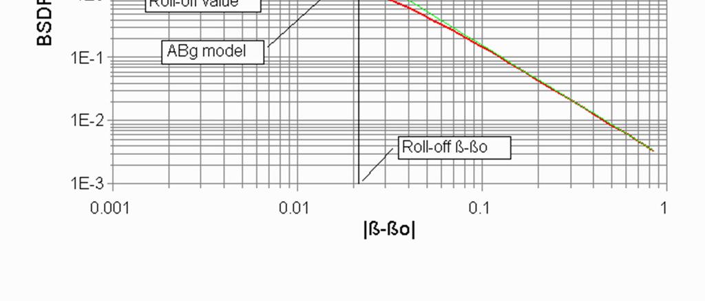
18 Cooke Triplet Example Using the Analysis Display Selected Paths option allows the user to see this 2 nd largest contributing path. This is important to determine if the paths is right on top of the signal or diffused out over the entire detector. The irradiance map works in conjunction with the ray path sorting and shows only the contribution from this second path.


19 Cooke Triplet Example If we coat the lenses with a 3 layer AR coating, you can see that all the ghosts no longer have paths to the detector. There is only one ray path and the signal is perfectly focused on the detector.
20 The Monte Carlo Method, Ray Splitting and Importance Sampling
21 Monte Carlo Ray-tracing and Sampling A crude Monte Carlo calculation is the simplest form of a probability experiment Perform an experiment N times, count the number of times n that the event occurs An estimate of the probability is: p e = n / N We can never get an exact value of p e, but we can make the uncertainty in p e arbitrarily small by increasing N. p( 1 p) The absolute uncertainty in p e is: σab= The relative uncertainty in p e is: σrel= (where p denotes the true pn probability) Hence, the accuracy of the result is inversely proportional to the square root of the number of trials (enough trials will always lead to the correct answer) On a higher level, Monte Carlo is a technique of numerical integration for complicated multiple integrals that cannot be done by more conventional numerical methods An integral such as... g( x1, x2,..., xl) dx 1dx 2... dx L can be estimated by sampling the variables x i, computing g for this set of samples, and repeating this process N times, summing the terms to obtain the estimate (histogram method, trapezoidal rule, Simpson s rule, etc.) N ( 1 p)
22 Variance reduction Variance reduction techniques are used to reduce the variance or uncertainty in the result of a Monte Carlo calculation after a given number of trials. Conversely, the number of trials needed to obtain a given uncertainty can be reduced. Splitting is a variance reduction technique used in Monte Carlo simulation. Ray splitting is used in TracePro. Importance sampling is a second commonly used method for variance reduction.
23 Ray Splitting Ray splitting is a technique in which a ray that strikes a surface can be split into several component rays, namely absorbed, specularly reflected, reflectively scattered, specularly transmitted, and transmissively scattered. The flux of the incident ray will also be split, with a fraction of the incident flux assigned to each component ray according to the properties of the surface. The process of splitting is repeated at each surface intercept, so that a tree-like structure of rays results. This process tremendously improves sampling in most cases, with a tolerable slowing of the raytrace.
24 incoming ray Ray Splitting
25 Importance Sampling Importance Sampling is used to improve the sampling of random events without dramatically increasing the number of rays started. Uses the scattering distribution function as a probability density to apportion a fraction of the scattered ray flux into a desired direction. May be used for emitted, scattered and diffracted rays only, on surface sources, scattering surfaces, diffracting surfaces and bulk scattering objects. Apply to object(s) for Bulk Scatter. Apply to surface(s) for all others.
26 Importance Sampling
27 Importance Sampled Flux Φ imp. samp. =Φ inc. Ω Φrandom =Φ TS Φ BSDF cosθ dω inc. imp. samp. TS = hemisphere BSDF cosθ dω
28 Importance Sampling Example random rays specular rays importance sampled rays


29 Importance Sampling Sources Source Example


30 Importance Sampling Scatter Surface Example Flux threshold typically set very low
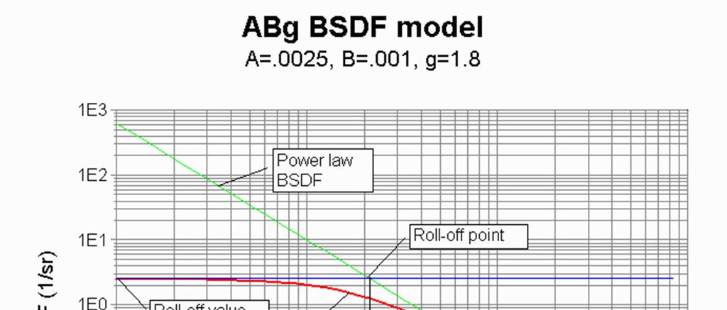
31 A World without Importance Sampling Suppose lens BTDF is A = 2e-5, B = 1e-6, g = 2. Lens scatters at angle of ~30º to get to detector, so p = f cosθ Ω 2 s θ 30º cos θ = 0.87 β-β f s = 8 x 10⁻⁵ Ω = (0.002 radian) 2 Ω = 4 x 10⁻⁶ p 2 = 2.77 x 10⁻¹⁰
32 A World without Importance Sampling Total probability is p total = p 1 p 2 = 3.46 x You must start 3 x rays to get 50% chance of one ray hitting the detector! Solution: define importance sampling target for lens surface. Probability p 2 increases to 1.0, total probability is 1/8. You can also define a target for sampling from the baffle to the lens, but this is not always necessary.
33 Stray Light and BSDF Used Definitions: NAME SYMBOL UNITS Irradiance E w/m 2 Radiance L w/m 2 -sr BSDF f 1/sr
34 Forms of Stray Light Straight Shots Where light from a bright source can bypass the intended path and finds a straight specular path to the focal plane. Ghost Images Ghost images are out-of-focus images of bright sources. Light must reflect an even number of times from lens surfaces. If the source is small each ghost looks like the aperture stop. If the ghost is focused on the image plane, the ghost looks like the source Singly-Scattered light Occurs when a stray light source illuminates the optics or some hardware that the focal plane sees. Some portion of the light will scatter into the field of view and become stray light. Once in the field of view, there is no way to eliminate it. Multi-Scattered Light Even when stray light sources do not illuminate the optics directly, they can still scatter from structure or baffles and then illuminate the optics. While this is always smaller than direct scatter it may be large enough to be of concern. Edge Diffraction When the ratio of aperture diameter to wavelength is relatively small (10^4 or smaller), edge diffraction from the aperture stop from out-of-field sources can be a significant source of stray light. Self-Emission of Infrared Systems Thermal imaging systems can have stray light caused by emission from the instrument itself. The peak of the blackbody emission curve for room temperature is at about 10µm. Thermal imagers typically subtract the background to enhance contrast, but this is best performed when the background is uniform. Combinations Of The Above
35 Four Methods to Reduce Stray Light Move It Moving the stray light by tilting a lens, moving the detector, or angling the offending stray light surface is the best way of getting stray light out of a system. You may need to add a beam dump to completely get rid of the problem. Block it Even when stray light sources do not illuminate the optics directly, they can still scatter from structure or baffles and then illuminate the optics. Using baffles is a great way to stop out of field sources from sending light directly to the detection device. Paint It Usually occurs when a shiny object is illuminated by a stray light source. Coating the offending shiny object with black paint usually reduces this stray light quite substantially but not completely to 0. For instance, black anodized aluminum can be 35% reflective but there are better black paints available several are in the 3 percent range but there can be problems with out gassing and degradation over time with these coatings. Some portion of the light will always scatter into the field of view and become stray light even with the best of coatings. Set a tolerable specification Coat It Especially important to get rid of ghost images - Ghost images are out-of-focus images of bright sources. Light must reflect an even number of times from lens surfaces. If the source is small each ghost looks like the aperture stop. If the ghost is focused on the image plane, the ghost looks like the source. To get rid of ghost images we coat the lenses with anti-reflective coatings to reduce ghosts 35
36 Importance Sampling for Stray Light Importance Sampling targets should be defined for each optical surface. The target should coincide with the real or virtual image as seen from that surface. The Auto Importance Sampling Setup feature will define targets for all optical surfaces. Importance sampling targets can always be added manually. Each surface can have an unlimited number of importance sampling targets. You may or may not need importance sampling on non-optical surfaces (lens barrels, baffle vanes, etc.). If you do define importance sampling targets for non-optical surfaces, surfaces that can see an image should have a target at that image. Surfaces that cannot see an image should have an importance sampling target at the next optical surface in the optical train. You should define importance sampling targets for diffracting surfaces, just like an optical surface. If only a few randomly scattered (non-importance-sampled) rays hit the image with high flux, causing hot spots, this usually means more importance sampling is needed. It is possible to overdo importance sampling, slowing the raytrace. A goal is to get about one ray on the image surface for each starting ray. Getting within an order of magnitude of this goal (either way) is OK. Modeling of bulk scattering will make this goal hard to achieve.
37 BSDF vs. Scattered Intensity BSDF is a generic term for measured scattering of light. There are three specific varieties of BSDF BRDF (Bidirectional Reflectance Distribution Function) BTDF (Bidirectional Transmittance Distribution Function) BDDF (Bidirectional Diffraction Distribution Function) Scattered Intensity or Cosine Corrected BSDF In the old days, people measured the scattering properties of a surface by measuring the scattered intensity (w/sr) normalized to the incident power (w). This differs from the BSDF by a factor of cosθ.
38 Typical BSDFs Polished surfaces BSDF from microroughness is proportional to Power Spectral Density (PSD) of roughness Values of g from 1.5 to 3.5, but 2 to 3 is more common B is small, 1e-6 to 1e-10, depending on surface statistics Contamination BSDF: similar in form to microroughness BSDF Diffuse surfaces If g = 0, BSDF is perfect Lambertian. Many baffle coatings come close to this. If not Lambertian, typically B is large, 0.1 to 1, and g is large, 2, 3, 4, 5, 6
39
40 ABg from RMS spreadsheet Input parameters: sigma (rms roughness) 50 Angstroms min wave 0.25 um autocorrelation length= 100 um wavelength = 0.5 um dn = 2 dn = difference in index of refraction R or T 0.95 R or T is (total) reflectance or transmittance Note: for a mirror, dn=2 Calculated ABC model coefficients: As = Strictly valid only for C=2 Bs = um Strictly valid only for C=2 C = 2 rms roughness/wave 0.01 Not valid if greater than 0.02 S = power spectrum D = Raw Integrated BSDF BSDF(0) = ABg coefficients for TracePro Bennett & Porteus TIS A = E-06 Correction factor B = E-10 g = 3 Corrected

41 Eliminate zero-order paths Examples of straight shot or zeroorder paths
42 What can be seen by the detector? Trace rays backward from the image plane to help determine what surfaces can be seen by the detector Make the detector surface into a surface source, or define a grid source immediately before the detector, pointing backward. Display the Flux Report to determine which surfaces the detector can see. Use Ray Sorting to see the paths of rays reaching those surfaces. In a similar way, trace rays forward to determine what surfaces can be illuminated by the source. Non-optical surfaces that can both be seen by the detector and illuminated by the source are critical surfaces. Either the illuminating or seeing path should be blocked by a baffle or otherwise mitigated. Consider different paths for cases of before and after the aperture stop.
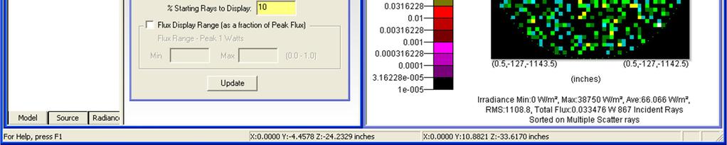
43 Analysis Mode Ray sorting: Use Analysis Tools For ray display to see the paths of stray rays. For irradiance maps to see irradiance distributions for specular vs. scattered rays. For irradiance maps to see the paths where stray rays for hot spots. Incident ray table Ray history table Path Sorting in TracePRO 7.1 Determine contributions of different stray light paths. Determine under-sampled paths and improve importance sampling. Simulation mode Ray Path Sorting Determine contributions of different stray light paths. Determine under-sampled paths and improve importance sampling.


44 Ray sorting for display


45 Ray sorting for ray type


46 Ray sorting for hot spots Use shift/drag to make rectangle Then choose Display Selected Rays

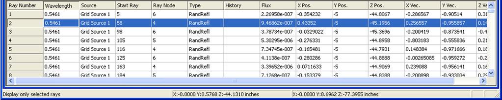
47 Incident Ray Table

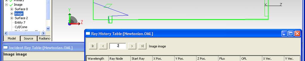
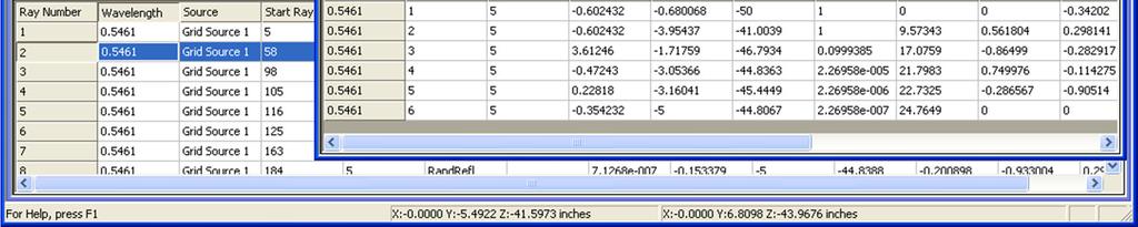
48 Ray History Table


49 Ray Path Sorting File Graphical path sorting available in Analysis mode Numeric-based path sorting available in analysis and simulation mode
50 Thank You
51 Questions and Answers
52 For Additional Information Please Contact: Lambda Research Corporation Littleton, MA
TracePro s Monte Carlo Raytracing Methods, reducing statistical noise, memory usage and raytrace times
 TracePro s Monte Carlo Raytracing Methods, reducing statistical noise, memory usage and raytrace times Presented by : Lambda Research Corporation 25 Porter Rd. Littleton, MA 01460 www.lambdares.com Moderator:
TracePro Stray Light Simulation
 TracePro Stray Light Simulation What Is Stray Light? A more descriptive term for stray light is unwanted light. In an optical imaging system, stray light is caused by light from a bright source shining
Ray and Path Sorting in TracePro
 Ray and Path Sorting in TracePro A Lambda Research Corporation Webinar December 15, 2016 Presenter Presenter Dave Jacobsen Sr. Application Engineer Lambda Research Corporation Moderator Mike Gauvin Vice
dq dt I = Irradiance or Light Intensity is Flux Φ per area A (W/m 2 ) Φ =
 Φ =") Radiometry (From Intro to Optics, Pedrotti -4) Radiometry is measurement of Emag radiation (light) Consider a small spherical source Total energy radiating from the body over some time is Q total Radiant
Radiometry (From Intro to Optics, Pedrotti -4) Radiometry is measurement of Emag radiation (light) Consider a small spherical source Total energy radiating from the body over some time is Q total Radiant
Accurate LED Source Modeling using TracePro
 Accurate LED Source Modeling using TracePro Presented by : Lambda Research Corporation 25 Porter Rd. Littleton, MA 01460 Moderator: Mike Gauvin Vice President of Sales and Marketing Lambda Research Corporation
EO-1 Stray Light Analysis Report No. 3
 EO-1 Stray Light Analysis Report No. 3 Submitted to: MIT Lincoln Laboratory 244 Wood Street Lexington, MA 02173 P.O. # AX-114413 May 4, 1998 Prepared by: Lambda Research Corporation 80 Taylor Street P.O.
dq dt I = Irradiance or Light Intensity is Flux Φ per area A (W/m 2 ) Φ =
 Φ =") Radiometry (From Intro to Optics, Pedrotti -4) Radiometry is measurement of Emag radiation (light) Consider a small spherical source Total energy radiating from the body over some time is Q total Radiant
Radiometry (From Intro to Optics, Pedrotti -4) Radiometry is measurement of Emag radiation (light) Consider a small spherical source Total energy radiating from the body over some time is Q total Radiant
The Rendering Equation. Computer Graphics CMU /15-662
 The Rendering Equation Computer Graphics CMU 15-462/15-662 Review: What is radiance? Radiance at point p in direction N is radiant energy ( #hits ) per unit time, per solid angle, per unit area perpendicular
Philpot & Philipson: Remote Sensing Fundamentals Interactions 3.1 W.D. Philpot, Cornell University, Fall 12
 Philpot & Philipson: Remote Sensing Fundamentals Interactions 3.1 W.D. Philpot, Cornell University, Fall 1 3. EM INTERACTIONS WITH MATERIALS In order for an object to be sensed, the object must reflect,
Design Verification and Analysis Tools in TracePro. Presented by : Lambda Research Corporation 25 Porter Rd. Littleton, MA
 Design Verification and Analysis Tools in TracePro Presented by : Lambda Research Corporation 25 Porter Rd. Littleton, MA 01460 www.lambdares.com Moderator: Andy Knight Technical Sales Manager Lambda Research
Scattering measurements. Guidelines for measurements service
 Scattering measurements Guidelines for measurements service 1 Content Introduction Light Tec Presentation Instruments availalable. Scattering measurements Refelctors Diffusers Colors issuses Volume Scattering
Ray Optics. Lecture 23. Chapter 23. Physics II. Course website:
 Lecture 23 Chapter 23 Physics II Ray Optics Course website: http://faculty.uml.edu/andriy_danylov/teaching/physicsii Let s finish talking about a diffraction grating Diffraction Grating Let s improve (more
Light Tec Scattering measurements guideline
 Light Tec Scattering measurements guideline 1 Our Laboratory Light Tec is equipped with a Photometric Laboratory (a dark room) including: Goniophotometers: REFLET 180S. High specular bench (10 meters),
Light Tec Scattering measurements guideline
 Light Tec Scattering measurements guideline 1 Our Laboratory Light Tec is equipped with a Photometric Laboratory (a dark room) including: Goniophotometers: REFLET180s. High specular bench (10 meters),
CENG 477 Introduction to Computer Graphics. Ray Tracing: Shading
 CENG 477 Introduction to Computer Graphics Ray Tracing: Shading Last Week Until now we learned: How to create the primary rays from the given camera and image plane parameters How to intersect these rays
Chapter 18 Ray Optics
 Chapter 18 Ray Optics Chapter Goal: To understand and apply the ray model of light. Slide 18-1 Chapter 18 Preview Looking Ahead Text p. 565 Slide 18-2 Wavefronts and Rays When visible light or other electromagnetic
Radiometry (From Intro to Optics, Pedrotti 1-4) Radiometry is measurement of Emag radiation (light) Consider a small spherical source Assume a black
 Radiometry is measurement of Emag radiation (light) Consider a small spherical source Assume a black") Radiometry (From Intro to Optics, Pedrotti -4) Radiometry is measurement of Emag radiation (light) Consider a small spherical source Assume a black body type emitter: uniform emission Total energy radiating
Radiometry (From Intro to Optics, Pedrotti -4) Radiometry is measurement of Emag radiation (light) Consider a small spherical source Assume a black body type emitter: uniform emission Total energy radiating
Light Tec Scattering measurements guideline
 Light Tec Scattering measurements guideline 1 Our Laboratory Light Tec is equipped with a Photometric Laboratory (a dark room) including: Goniophotometers: REFLET 180S. High specular bench (10 meters),
Light Tec Scattering measurements guideline
 Light Tec Scattering measurements guideline 1 2 Light Tec Locations REFLET assembling plant, Aix-en-Provence, France Light Tec GmbH, Munich, Germany German office Light Tec Sarl, Hyères, France Main office
All forms of EM waves travel at the speed of light in a vacuum = 3.00 x 10 8 m/s This speed is constant in air as well
 Pre AP Physics Light & Optics Chapters 14-16 Light is an electromagnetic wave Electromagnetic waves: Oscillating electric and magnetic fields that are perpendicular to the direction the wave moves Difference
Local Illumination. CMPT 361 Introduction to Computer Graphics Torsten Möller. Machiraju/Zhang/Möller
 Local Illumination CMPT 361 Introduction to Computer Graphics Torsten Möller Graphics Pipeline Hardware Modelling Transform Visibility Illumination + Shading Perception, Interaction Color Texture/ Realism
Ray Optics I. Last time, finished EM theory Looked at complex boundary problems TIR: Snell s law complex Metal mirrors: index complex
 Phys 531 Lecture 8 20 September 2005 Ray Optics I Last time, finished EM theory Looked at complex boundary problems TIR: Snell s law complex Metal mirrors: index complex Today shift gears, start applying
13 Distribution Ray Tracing
 13 In (hereafter abbreviated as DRT ), our goal is to render a scene as accurately as possible. Whereas Basic Ray Tracing computed a very crude approximation to radiance at a point, in DRT we will attempt
How to use the new TracePro Solar Utility for comprehensive solar calculations
 How to use the new TracePro Solar Utility for comprehensive solar calculations Presented by : Lambda Research Corporation 25 Porter Rd. Littleton, MA 01460 Moderators: Andy Knight Technical Sales Manager
The Rendering Equation. Computer Graphics CMU /15-662, Fall 2016
 The Rendering Equation Computer Graphics CMU 15-462/15-662, Fall 2016 Review: What is radiance? Radiance at point p in direction N is radiant energy ( #hits ) per unit time, per solid angle, per unit area
Global Illumination The Game of Light Transport. Jian Huang
 Global Illumination The Game of Light Transport Jian Huang Looking Back Ray-tracing and radiosity both computes global illumination Is there a more general methodology? It s a game of light transport.
specular diffuse reflection.
 Lesson 8 Light and Optics The Nature of Light Properties of Light: Reflection Refraction Interference Diffraction Polarization Dispersion and Prisms Total Internal Reflection Huygens s Principle The Nature
Stray light calculation methods with optical ray trace software
 Stray light calculation methods with optical ray trace software Gary L. Peterson Breault Research Organization 6400 East Grant Road, Suite 350, Tucson, Arizona 85715 Copyright 1999, Society of Photo-Optical
LIGHT. Speed of light Law of Reflection Refraction Snell s Law Mirrors Lenses
 LIGHT Speed of light Law of Reflection Refraction Snell s Law Mirrors Lenses Light = Electromagnetic Wave Requires No Medium to Travel Oscillating Electric and Magnetic Field Travel at the speed of light
Reflection and Shading
 Reflection and Shading R. J. Renka Department of Computer Science & Engineering University of North Texas 10/19/2015 Light Sources Realistic rendering requires that we model the interaction between light
MODELING LED LIGHTING COLOR EFFECTS IN MODERN OPTICAL ANALYSIS SOFTWARE LED Professional Magazine Webinar 10/27/2015
 MODELING LED LIGHTING COLOR EFFECTS IN MODERN OPTICAL ANALYSIS SOFTWARE LED Professional Magazine Webinar 10/27/2015 Presenter Dave Jacobsen Senior Application Engineer at Lambda Research Corporation for
Understanding Variability
 Understanding Variability Why so different? Light and Optics Pinhole camera model Perspective projection Thin lens model Fundamental equation Distortion: spherical & chromatic aberration, radial distortion
Comp 410/510 Computer Graphics. Spring Shading
 Comp 410/510 Computer Graphics Spring 2017 Shading Why we need shading Suppose we build a model of a sphere using many polygons and then color it using a fixed color. We get something like But we rather
2/1/10. Outline. The Radiance Equation. Light: Flux Equilibrium. Light: Radiant Power. Light: Equation. Radiance. Jan Kautz
 Outline Jan Kautz Basic terms in radiometry Radiance Reflectance The operator form of the radiance equation Meaning of the operator form Approximations to the radiance equation 2005 Mel Slater, 2006 Céline
Optimizing the TracePro Optimization Process
 Optimizing the TracePro Optimization Process A TracePro Webinar December 17, 2014 Presenter Presenter Dave Jacobsen Sr. Application Engineer Lambda Research Corporation Moderator Mike Gauvin Vice President
Lecture 7 Notes: 07 / 11. Reflection and refraction
 Lecture 7 Notes: 07 / 11 Reflection and refraction When an electromagnetic wave, such as light, encounters the surface of a medium, some of it is reflected off the surface, while some crosses the boundary
Ray Optics. Lecture 23. Chapter 34. Physics II. Course website:
 Lecture 23 Chapter 34 Physics II Ray Optics Course website: http://faculty.uml.edu/andriy_danylov/teaching/physicsii Today we are going to discuss: Chapter 34: Section 34.1-3 Ray Optics Ray Optics Wave
At the interface between two materials, where light can be reflected or refracted. Within a material, where the light can be scattered or absorbed.
 At the interface between two materials, where light can be reflected or refracted. Within a material, where the light can be scattered or absorbed. The eye sees by focusing a diverging bundle of rays from
Optical Reflector Design using the TracePro Interactive Optimizer
 Optical Reflector Design using the TracePro Interactive Optimizer Presented by : Lambda Research Corporation 25 Porter Rd. Littleton, MA 01460 www.lambdares.com Moderator: Andy Knight Technical Sales Manager
Lighting affects appearance
 Lighting affects appearance 1 Source emits photons Light And then some reach the eye/camera. Photons travel in a straight line When they hit an object they: bounce off in a new direction or are absorbed
Capturing light. Source: A. Efros
 Capturing light Source: A. Efros Review Pinhole projection models What are vanishing points and vanishing lines? What is orthographic projection? How can we approximate orthographic projection? Lenses
Ø Sampling Theory" Ø Fourier Analysis Ø Anti-aliasing Ø Supersampling Strategies" Ø The Hall illumination model. Ø Original ray tracing paper
 CS 431/636 Advanced Rendering Techniques Ø Dr. David Breen Ø Korman 105D Ø Wednesday 6PM 8:50PM Presentation 6 5/16/12 Questions from ast Time? Ø Sampling Theory" Ø Fourier Analysis Ø Anti-aliasing Ø Supersampling
Light: Geometric Optics
 Light: Geometric Optics The Ray Model of Light Light very often travels in straight lines. We represent light using rays, which are straight lines emanating from an object. This is an idealization, but
PHYSICS. Chapter 34 Lecture FOR SCIENTISTS AND ENGINEERS A STRATEGIC APPROACH 4/E RANDALL D. KNIGHT
 PHYSICS FOR SCIENTISTS AND ENGINEERS A STRATEGIC APPROACH 4/E Chapter 34 Lecture RANDALL D. KNIGHT Chapter 34 Ray Optics IN THIS CHAPTER, you will learn about and apply the ray model of light Slide 34-2
TracePro Tutorial Tissue Optics
 TracePro Tutorial Tissue Optics Splitting the Screen To view the System Tree, select Window Split, then drag the mouse to the right to position the vertical splitter bar. Alternatively, you can place your
The Death of the Aerial Image
 Tutor50.doc: Version 5/9/05 T h e L i t h o g r a p h y E x p e r t (August 005) The Death of the Aerial Image Chris A. Mack, KLA-Tencor, FINLE Division, Austin, Texas The aerial image is, quite literally,
Tips, Tricks, and Shortcuts to Improve Productivity and Efficiency with TracePro
 Tips, Tricks, and Shortcuts to Improve Productivity and Efficiency with TracePro Presented by : Lambda Research Corporation 25 Porter Rd. Littleton, MA 01460 www.lambdares.com Moderator: Andy Knight Technical
Light and Electromagnetic Waves. Honors Physics
 Light and Electromagnetic Waves Honors Physics Electromagnetic Waves EM waves are a result of accelerated charges and disturbances in electric and magnetic fields (Radio wave example here) As electrons
Reflection and Refraction of Light
 PC1222 Fundamentals of Physics II Reflection and Refraction of Light 1 Objectives Investigate for reflection of rays from a plane surface, the dependence of the angle of reflection on the angle of incidence.
Illumination & Shading
 Illumination & Shading Goals Introduce the types of light-material interactions Build a simple reflection model---the Phong model--- that can be used with real time graphics hardware Why we need Illumination
Paths, diffuse interreflections, caching and radiometry. D.A. Forsyth
 Paths, diffuse interreflections, caching and radiometry D.A. Forsyth How we got here We want to render diffuse interreflections strategy: compute approximation B-hat, then gather B = E +(ρk)e +(ρk)( ˆB
SESSION 5: INVESTIGATING LIGHT. Key Concepts. X-planation. Physical Sciences Grade In this session we:
 SESSION 5: INVESTIGATING LIGHT Key Concepts In this session we: Explain what light is, where light comes from and why it is important Identify what happens when light strikes the surface of different objects
Introduction. Lighting model Light reflection model Local illumination model Reflectance model BRDF
 Shading Introduction Affine transformations help us to place objects into a scene. Before creating images of these objects, we ll look at models for how light interacts with their surfaces. Such a model
Visual cues to 3D geometry. Light Reflection and Advanced Shading. Shading. Recognizing materials. size (perspective) occlusion shading
 occlusion shading") Visual cues to 3D geometry Light Reflection and Advanced Shading size (perspective) occlusion shading CS 4620 Lecture 17 1 2 Shading Recognizing materials Variation in observed color across an object strongly
Visual cues to 3D geometry Light Reflection and Advanced Shading size (perspective) occlusion shading CS 4620 Lecture 17 1 2 Shading Recognizing materials Variation in observed color across an object strongly
Illumination in Computer Graphics
 Illumination in Computer Graphics Ann McNamara Illumination in Computer Graphics Definition of light sources. Analysis of interaction between light and objects in a scene. Rendering images that are faithful
Outline The Refraction of Light Forming Images with a Plane Mirror 26-3 Spherical Mirror 26-4 Ray Tracing and the Mirror Equation
 Chapter 6 Geometrical Optics Outline 6-1 The Reflection of Light 6- Forming Images with a Plane Mirror 6-3 Spherical Mirror 6-4 Ray Tracing and the Mirror Equation 6-5 The Refraction of Light 6-6 Ray Tracing
Lecture 7 - Path Tracing
 INFOMAGR Advanced Graphics Jacco Bikker - November 2016 - February 2017 Lecture 7 - I x, x = g(x, x ) ε x, x + S ρ x, x, x I x, x dx Welcome! Today s Agenda: Introduction Advanced Graphics 3 Introduction
Reflections. I feel pretty, oh so pretty
 Reflections I feel pretty, oh so pretty Objectives By the end of the lesson, you should be able to: Draw an accurate reflective angle Determine the focal length of a spherical mirror Light Review Light
Path Tracing part 2. Steve Rotenberg CSE168: Rendering Algorithms UCSD, Spring 2017
 Path Tracing part 2 Steve Rotenberg CSE168: Rendering Algorithms UCSD, Spring 2017 Monte Carlo Integration Monte Carlo Integration The rendering (& radiance) equation is an infinitely recursive integral
Simple Lighting/Illumination Models
 Simple Lighting/Illumination Models Scene rendered using direct lighting only Photograph Scene rendered using a physically-based global illumination model with manual tuning of colors (Frederic Drago and
Geometrical modeling of light scattering from paper substrates
 Geometrical modeling of light scattering from paper substrates Peter Hansson Department of Engineering ciences The Ångström Laboratory, Uppsala University Box 534, E-75 Uppsala, weden Abstract A light
Physical Optics. You can observe a lot just by watching. Yogi Berra ( )
") Physical Optics You can observe a lot just by watching. Yogi Berra (1925-2015) OBJECTIVES To observe some interference and diffraction phenomena with visible light. THEORY In a previous experiment you
Physical Optics You can observe a lot just by watching. Yogi Berra (1925-2015) OBJECTIVES To observe some interference and diffraction phenomena with visible light. THEORY In a previous experiment you
Ray Optics. Ray model Reflection Refraction, total internal reflection Color dispersion Lenses Image formation Magnification Spherical mirrors
 Ray Optics Ray model Reflection Refraction, total internal reflection Color dispersion Lenses Image formation Magnification Spherical mirrors 1 Ray optics Optical imaging and color in medicine Integral
Physics 11 Chapter 18: Ray Optics
 Physics 11 Chapter 18: Ray Optics "... Everything can be taken from a man but one thing; the last of the human freedoms to choose one s attitude in any given set of circumstances, to choose one s own way.
Radiometry & BRDFs CS295, Spring 2017 Shuang Zhao
 Radiometry & BRDFs CS295, Spring 2017 Shuang Zhao Computer Science Department University of California, Irvine CS295, Spring 2017 Shuang Zhao 1 Today s Lecture Radiometry Physics of light BRDFs How materials
How to Use the Luminit LSD Scatter Model
 How to Use the Luminit LSD Scatter Model Summary: This article describes the characteristics and use of Luminit s LSD scatter model in OpticStudio. The scatter model presented here is the idealized scatter
Geometrical Optics INTRODUCTION. Wave Fronts and Rays
 Geometrical Optics INTRODUCTION In this experiment, the optical characteristics of mirrors, lenses, and prisms will be studied based on using the following physics definitions and relationships plus simple
What is it? How does it work? How do we use it?
 What is it? How does it work? How do we use it? Dual Nature http://www.youtube.com/watch?v=dfpeprq7ogc o Electromagnetic Waves display wave behavior o Created by oscillating electric and magnetic fields
Physics 1C, Summer 2011 (Session 1) Practice Midterm 2 (50+4 points) Solutions
 Practice Midterm 2 (50+4 points) Solutions") Physics 1C, Summer 2011 (Session 1) Practice Midterm 2 (50+4 points) s Problem 1 (5x2 = 10 points) Label the following statements as True or False, with a one- or two-sentence explanation for why you chose
Physics 1C, Summer 2011 (Session 1) Practice Midterm 2 (50+4 points) s Problem 1 (5x2 = 10 points) Label the following statements as True or False, with a one- or two-sentence explanation for why you chose
Optical Scattering. Analysis. Measurement and SPIE PRESS. John C. Stover THIRD EDITION. Bellingham, Washington USA
 Optical Scattering Measurement and Analysis THIRD EDITION John C. Stover SPIE PRESS Bellingham, Washington USA Contents Preface to the First Edition xiii Preface to the Second Edition xv Acknowledgments
Shading. Brian Curless CSE 557 Autumn 2017
 Shading Brian Curless CSE 557 Autumn 2017 1 Reading Optional: Angel and Shreiner: chapter 5. Marschner and Shirley: chapter 10, chapter 17. Further reading: OpenGL red book, chapter 5. 2 Basic 3D graphics
CS 5625 Lec 2: Shading Models
 CS 5625 Lec 2: Shading Models Kavita Bala Spring 2013 Shading Models Chapter 7 Next few weeks Textures Graphics Pipeline Light Emission To compute images What are the light sources? Light Propagation Fog/Clear?
Nicholas J. Giordano. Chapter 24. Geometrical Optics. Marilyn Akins, PhD Broome Community College
 Nicholas J. Giordano www.cengage.com/physics/giordano Chapter 24 Geometrical Optics Marilyn Akins, PhD Broome Community College Optics The study of light is called optics Some highlights in the history
Geometrical Optics. Name ID TA. Partners. Date Section. Please do not scratch, polish or touch the surface of the mirror.
 Geometrical Optics Name ID TA Partners Date Section Please do not scratch, polish or touch the surface of the mirror. 1. Application of geometrical optics: 2. Real and virtual images: One easy method to
Raytracing. COSC 4328/5327 Scott A. King
 Raytracing COSC 4328/5327 Scott A. King Basic Ray Casting Method pixels in screen Shoot ray p from the eye through the pixel. Find closest ray-object intersection. Get color at intersection Basic Ray Casting
Illumination Design, Analysis, and Optimization Software
 SUPERIOR OPTO-MECHANICAL SOFTWARE Illumination Design, Analysis, and Optimization Software TracePro is award-winning opto-mechanical software used for design, analysis, and optimization of optical and
PHY 112: Light, Color and Vision. Lecture 11. Prof. Clark McGrew Physics D 134. Review for Exam. Lecture 11 PHY 112 Lecture 1
 PHY 112: Light, Color and Vision Lecture 11 Prof. Clark McGrew Physics D 134 Review for Exam Lecture 11 PHY 112 Lecture 1 From Last Time Lenses Ray tracing a Convex Lens Announcements The midterm is Thursday
Specular reflection. Lighting II. Snell s Law. Refraction at boundary of media
 Specular reflection Lighting II CS 465 Lecture 19 Smooth surfaces of pure materials have ideal specular reflection (said this before) Metals (conductors) and dielectrics (insulators) behave differently
Lecture 17: Recursive Ray Tracing. Where is the way where light dwelleth? Job 38:19
 Lecture 17: Recursive Ray Tracing Where is the way where light dwelleth? Job 38:19 1. Raster Graphics Typical graphics terminals today are raster displays. A raster display renders a picture scan line
INFOGR Computer Graphics. J. Bikker - April-July Lecture 10: Shading Models. Welcome!
 INFOGR Computer Graphics J. Bikker - April-July 2016 - Lecture 10: Shading Models Welcome! Today s Agenda: Introduction Light Transport Materials Sensors Shading INFOGR Lecture 10 Shading Models 3 Introduction
Rendering: Reality. Eye acts as pinhole camera. Photons from light hit objects
 Basic Ray Tracing Rendering: Reality Eye acts as pinhole camera Photons from light hit objects Rendering: Reality Eye acts as pinhole camera Photons from light hit objects Rendering: Reality Eye acts as
I have a meeting with Peter Lee and Bob Cosgrove on Wednesday to discuss the future of the cluster. Computer Graphics
 Announcements Assignment 4 will be out later today Problem Set 3 is due today or tomorrow by 9am in my mail box (4 th floor NSH) How are the machines working out? I have a meeting with Peter Lee and Bob
The Question. What are the 4 types of interactions that waves can have when they encounter an object?
 The Question What are the 4 types of interactions that waves can have when they encounter an object? Waves, Wave fronts and Rays Wave Front: Crests of the waves. Rays: Lines that are perpendicular to the
Refraction of Light. This bending of the ray is called refraction
 Refraction & Lenses Refraction of Light When a ray of light traveling through a transparent medium encounters a boundary leading into another transparent medium, part of the ray is reflected and part of
Motivation. Monte Carlo Path Tracing. Monte Carlo Path Tracing. Monte Carlo Path Tracing. Monte Carlo Path Tracing
 Advanced Computer Graphics (Spring 2013) CS 283, Lecture 11: Monte Carlo Path Tracing Ravi Ramamoorthi http://inst.eecs.berkeley.edu/~cs283/sp13 Motivation General solution to rendering and global illumination
Optics Vac Work MT 2008
 Optics Vac Work MT 2008 1. Explain what is meant by the Fraunhofer condition for diffraction. [4] An aperture lies in the plane z = 0 and has amplitude transmission function T(y) independent of x. It is
PHYS 219 General Physics: Electricity, Light and Modern Physics
 PHYS 219 General Physics: Electricity, Light and Modern Physics Exam 2 is scheduled on Tuesday, March 26 @ 8 10 PM In Physics 114 It will cover four Chapters 21, 22, 23, and 24. Start reviewing lecture
Optics II. Reflection and Mirrors
 Optics II Reflection and Mirrors Geometric Optics Using a Ray Approximation Light travels in a straight-line path in a homogeneous medium until it encounters a boundary between two different media The
Optics INTRODUCTION DISCUSSION OF PRINCIPLES. Reflection by a Plane Mirror
 Optics INTRODUCTION Geometric optics is one of the oldest branches of physics, dealing with the laws of reflection and refraction. Reflection takes place on the surface of an object, and refraction occurs
Lab 10 - GEOMETRICAL OPTICS
 L10-1 Name Date Partners OBJECTIVES OVERVIEW Lab 10 - GEOMETRICAL OPTICS To examine Snell s Law. To observe total internal reflection. To understand and use the lens equations. To find the focal length
Algebra Based Physics
 Slide 1 / 66 Slide 2 / 66 Algebra Based Physics Geometric Optics 2015-12-01 www.njctl.org Table of ontents Slide 3 / 66 lick on the topic to go to that section Reflection Spherical Mirror Refraction and
Lighting and Reflectance COS 426
 ighting and Reflectance COS 426 Ray Casting R2mage *RayCast(R3Scene *scene, int width, int height) { R2mage *image = new R2mage(width, height); for (int i = 0; i < width; i++) { for (int j = 0; j < height;
This tutorial illustrates how to use TracePro for the analysis of LCD Back Lights. The steps include:
 Requirements Models: None Properties: None Editions: TracePro Expert Introduction This tutorial illustrates how to use TracePro for the analysis of LCD Back Lights. The steps include: Generating a solid
Class 11 Introduction to Surface BRDF and Atmospheric Scattering. Class 12/13 - Measurements of Surface BRDF and Atmospheric Scattering
 University of Maryland Baltimore County - UMBC Phys650 - Special Topics in Experimental Atmospheric Physics (Spring 2009) J. V. Martins and M. H. Tabacniks http://userpages.umbc.edu/~martins/phys650/ Class
Shading. Why we need shading. Scattering. Shading. Objectives
 Shading Why we need shading Objectives Learn to shade objects so their images appear three-dimensional Suppose we build a model of a sphere using many polygons and color it with glcolor. We get something
Global Illumination. CMPT 361 Introduction to Computer Graphics Torsten Möller. Machiraju/Zhang/Möller
 Global Illumination CMPT 361 Introduction to Computer Graphics Torsten Möller Reading Foley, van Dam (better): Chapter 16.7-13 Angel: Chapter 5.11, 11.1-11.5 2 Limitation of local illumination A concrete
Optics. a- Before the beginning of the nineteenth century, light was considered to be a stream of particles.
 Optics 1- Light Nature: a- Before the beginning of the nineteenth century, light was considered to be a stream of particles. The particles were either emitted by the object being viewed or emanated from
Light. Electromagnetic wave with wave-like nature Refraction Interference Diffraction
 Light Electromagnetic wave with wave-like nature Refraction Interference Diffraction Light Electromagnetic wave with wave-like nature Refraction Interference Diffraction Photons with particle-like nature
Evaluation of radiative power loading on WEST metallic in-vessel components
 Evaluation of radiative power loading on WEST metallic in-vessel components M-H. Aumeunier 1, P. Moreau, J. Bucalossi, M. Firdaouss CEA/IRFM F-13108 Saint-Paul-Lez-Durance, France E-mail: marie-helene.aumeunier@cea.fr
Shading and Illumination
 Shading and Illumination OpenGL Shading Without Shading With Shading Physics Bidirectional Reflectance Distribution Function (BRDF) f r (ω i,ω ) = dl(ω ) L(ω i )cosθ i dω i = dl(ω ) L(ω i )( ω i n)dω