Council for Optical Radiation Measurements (CORM) 2016 Annual Technical Conference May 15 18, 2016, Gaithersburg, MD
|
|
|
- Angelina Anderson
- 6 years ago
- Views:
Transcription
1 Council for Optical Radiation Measurements (CORM) 2016 Annual Technical Conference May 15 18, 2016, Gaithersburg, MD Multispectral measurements of emissive and reflective properties of displays: Application to outdoor performances and physico-realistic ray tracing simulations Pierre BOHER, ELDIM, 1185 rue d Epron, Hérouville St Clair, France pboher@eldim.fr Tel : Slide #1
2 Outline 1. Introduction: Purpose of the study 2. Experimental technique a) Emissive properties b) Reflective properties i. Collimated beam spectral BRDF ii. Full diffused spectral reflectance 3. Experimental results a) Reflective properties of a metallic surface b) LCD with variable top polarizer c) OLED display 3. Ray-tracing simulations 4. Conclusions Slide #2
3 Introduction Slide #3

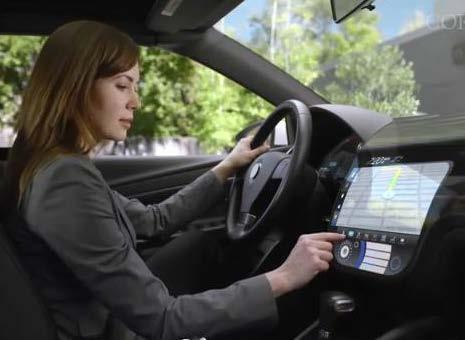
4 Part I: Introduction All displays used outdoor suffer from parasitic reflections that affect their contrast and luminance properties. This is always the case for mobile applications like phone cell displays or tablet displays. For automotive applications it can be critical since parasitic illumination can have a direct impact of the security Purpose of the paper is to quantify these imperfections to be able to: Compare displays efficiently Realize physico-realistic display simulations Slide #4

 Main drawbacks: Fixed illumination conditions (spectral content and geometry).")

5 Part I: Introduction Specular included Specular excluded Standard way to measure display under external illumination: hemispherical reflection with or without specular (IDMS section 11.3) Main drawbacks: Fixed illumination conditions (spectral content and geometry). Fixed detection geometry Additional specular source possible but with increasing complexity Strategy of the study: Make Spectral and normalized measurements of the reflective properties Measure full diffused and collimated beam illumination independently Slide #5
6 Part I: Introduction The Emissive Properties E(θ e, φ e, GL): Color or luminance for each pixel (θ e, φ e ) direction of emitted beam GL grey level of the pixel The spectral reflectance R(θ r φ r, λ) using full diffused illumination (θ r, φ r ) direction of reflected beam λ wavelength dependence The BRDF (θ I, φ I, θ e, φ e, λ) using collimated illumination: (θ I, φ I ) direction of incidence beam (θ e, φ e ) direction of reflected beam λ wavelength dependence Mandatory for simulation of color images Mandatory for simulation under any illumination conditions Slide #6

7 Experimental techniques Slide #7
8 Part II: Experimental techniques Angular aperture & spot size are controlled independently Multispectral measurement with 31 band-pass filters Slide #8
 400nm 410nm 420nm 430nm 442nm 450nm 458nm 467nm 480nm 488nm 500nm 510nm 520nm 532nm 540nm 550nm 568nm 580nm 589nm 600nm 610nm 620nm 632nm 640nm")
9 Part II: Experimental techniques Transmittance (%) Wavelength (nm) 400nm 410nm 420nm 430nm 442nm 450nm 458nm 467nm 480nm 488nm 500nm 510nm 520nm 532nm 540nm 550nm 568nm 580nm 589nm 600nm 610nm 620nm 632nm 640nm 647nm 650nm 656nm 671nm 676nm 690nm 694nm Principle : band pass filter measurements from 400 to 700nm 2. 10nm wavelength resolution 3. ±88 incidence & 2mm spot size 4. Luminance and color can be computed Slide #9
10 Part II: Experimental techniques Collimated or full diffused illuminations can be applied Multispectral measurement is made with 31 band pass filters Slide #10
11 Part II: Experimental techniques Full diffused reflectance measurement The spectral reflectance is full diffused illumination is given by dlr ( θr, ϕr, λ) R ( θr, ϕr, λ) = dl ( θ, ϕ, λ) (θ r,φ r ) is the polar coordinates of the detection direction dl r and dl w are the radiance measured on sample and Spectralon R White is the reflection coefficient of the Spectralon Parasitic reflections are corrected using a light trap White r r z dω r Incident beam θ r Reflected beam φφ r y x Measured directly by the instrument Slide #11
12 Part II: Experimental techniques Collimated beam spectral BRDF measurement The spectral BRDF is collimated beam illumination is given by dlr ( θr, ϕr, λ) BRDF ( θi, ϕi, θr, ϕr, λ) = de ( θ, ϕ, λ) dl r is the radiance diffused by the sample de i is the irradiance of the sample i i i Incident beam dω i BRDF( θ, ϕ, θ, ϕ, λ) = i i r r R 2πStr white φφ i θ i z ( θ, λ) L θ r r dω r i, θr, ϕr, Reflected beam λ)cosθ dω L White is the radiance measured on spectralon and R White its reflection coefficient r dl r White ( θ, ϕ, λ) i r ( θ, ϕ r r φφ r y x Measured directly by the instrument Slide #12
13 Calibration of the BRDF measurements BRDF (sr-1) 0.10 Spectralon is not Lambertian at high incidence angles Angle (deg) Measurements on the white Spectralon sample For different incidence angles and versus the detection angle in the incidence plane Slide #13


14 Part II: Experimental techniques CCD camera Band pass filters Optical fiber Additional optics Fourier optics Sample Power supply Xenon lamp Setup for BRDF measurements May 16 th, 2016 Slide #14
15 Experimental results Slide #15
16 Part III: Anisotropic metallic surface Brushed copper sample with transparent layer protection Slide #16
17 Part III: Anisotropic metallic surface Purple Zone Reflectance pattern vs wavelength Yellow Zone Spectral reflectance in full diffused illumination of Cu sample Protection layer has not the same thickness Slide #17
18 Part III: Anisotropic metallic surface Purple Zone BRDF pattern versus wavelength BDRF is modulated by the interference fringes Yellow Zone BRDF measurements of Cu sample for incidence 30 along azimuth 0 Slide #18
19 Part III: Anisotropic metallic surface Standard Fourier plane is geometrically distorted (1) Normal Fourier Plane BRDF Fourier Plane XX = θθ RR ccccccφφ RR YY = θθ RR ssssssφφ RR XX = θθ NN ccccccφφ NN YY = θθ NN ssssssφφ NN (1) L. Simonot, G. Obein, Geometrical considerations in analyzing isotropic or anisotropic surface reflections, Applied Optics, Vol. 46, N 14, 2615 (2007) Slide #19

20 Part III: Anisotropic metallic surface Standard Fourier Space BDRF space emphasize the brushing direction BRDF Space BRDF measurements on purple zone of Cu sample for incidence 30 along azimuth 0 and wavelength 600nm Slide #20

21 Part III: Anisotropic metallic surface Purple Zone Interference fringes Modulate the BRDF patterns Yellow Zone BRDF measurements of Cu sample in the BRDF space for incidence 30 along azimuth 90 Slide #21
 Color simulation of Cu sample using full diffused reflectance Slide #22 0.")
22 Part III: Anisotropic metallic surface 0.5 Ray emission lamp 0.4 Emission (a.u) Wavelength (nm) Color coordinates in the u v 1976 CIE system u' v' Yellow Purple Yellow Purple Incidence angle (deg) Color simulation of Cu sample using full diffused reflectance Slide # Incidence angle (deg)
23 Part III: LCD with variable top polarizer A demo LCD display with four different regions where the top polarizer has been replaced by a different polarizers films o Anti Glare 30 (AR30) o Anti Glare 380 (AR380) o Anti Glare Low Reflection (AGLR) o Anti Glare Anti Reflection (AGAR) Slide #23
24 Part III: LCD with variable top polarizer Intrinsic emissive properties AG30 AG380 Better contrast due to lower black state AGLR AGAR Luminance contrast for the four top polarizers Slide #24
25 Part III: LCD with variable top polarizer AG30 AG380 Much lower reflectance AGLR AGAR Full diffused spectral reflectance at 600nm for the 4 top polarizers Slide #25
26 Part III: LCD with variable top polarizer 500cd/m 2 Luminance contrast at normal incidence versus full diffused luminance for the four top polarizers: illuminant D65 Slide #26

27 Part III: LCD with variable top polarizer AG30 & AG380 comparable AG30 AG380 AGAR Best solution AGLR AGAR Luminance contrast with 500cd/m 2 full diffused illumination for the four top polarizers: isolevel = 10, illuminant D65 Slide #27
28 Part III: LCD with variable top polarizer AG30 AG380 Along horizontal azimuth AGLR AGAR BRDF measured at 600nm with collimated beam illumination at 25 for the four top polarizers: isolevel at 0.1, logarithmic scale Slide #28
29 Part III: LCD with variable top polarizer AG380 much glossier than AG30 BRDF measured at 600nm along horizontal azimuth with collimated beam illumination at 25 for the four top polarizers Slide #29
30 Part III: LCD with variable top polarizer AG380 & AG30 have now different performances Luminance contrast versus illuminance computed for the four top polarizers at specular position and 20 of incidence: Collimated beam illumination at 25, illuminant D65 Slide #30
31 Part III: OLED display Standard Fourier Space BRDF Space BRDF measured at 689nm on curved OLED TV for an incident beam 40 incidence and different azimuths Slide #31

32 Ray tracing simulations Slide #32
33 Part IV: Ray tracing simulations Proposal for integration in the Information Display Measurement Standard (ICDM) EXR file formats for saving all emissive or reflective properties of a display ( Emissive viewing angle behavior is measured & stored as : Parts : Data input value (From 0 to 255) as Layers : R, G & B pixels Channels : Per X, Y & Z or per wavelength values versus angle Reflective BRDF behavior is measured & stored as Layers : Input angles Channels : Per wavelength output values versus angle Slide #33

34 Part IV: Ray tracing simulations Viewing angle emissive properties of a display in one file Slide #34


35 Part IV: Ray tracing simulations Ocean light simulator Floor illumination in building General purpose light simulation software Building with solar control coated glass Perfume bottles Car render based on measured paint and glass optical data See for details Slide #35
36 Part IV: Ray tracing simulations Software features for display simulation Available Emissive properties Use directly measured viewing angle properties Interpolation for any grey level value on each sub-pixel Simulation of any high resolution color image Capacity to introduce some in-homogeneities Reflective properties Use directly measured spectral BRDF properties Interpolation for any incidence angle for isotropic surfaces Interpolation for any incidence & azimuth angle for anisotropic surfaces (in-progress) Polarization properties (in the future) Use of measured polarization state of the light emitted by the display Use of polarization dependence of the spectral BRDF in progress Slide #36
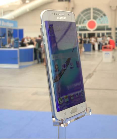
37 Part IV: Ray tracing simulations Without reflection Simulation of Samsung curved LCD display Slide #37


38 Part IV: Ray tracing simulations With diffusing reflection properties Diffusing Glossy BRDF (str-1) Simulation of Samsung curved LCD display Angle (deg) BRDF at 30 and 550nm Slide #38
 10 1 0.")
 BRDF at 30 and 550nm May 16 th, 2016")
39 Part IV: Ray tracing simulations With glossy reflection properties Diffusing Glossy BRDF (str-1) Simulation of Samsung curved LCD display Angle (deg) BRDF at 30 and 550nm May 16 th, 2016 CORM Annual Technical Conference, Gaithersburg Slide #39
40 Conclusions Slide #40
41 Conclusions EZContrast-MS allows different types of multispectral measurement for the full viewing angle o o o Emissive properties : spectral radiance, color & luminance Spectral reflectance for full diffused illumination Spectral BRDF for collimated beam illumination Computations: o o o o Computation of luminance contrast under any illumination conditions Computation of color gamut under any illumination conditions Simultaneous full diffused and collimated illuminations possible Computations for all the illumination conditions found in standards possible! Physico-realistic rendering of any display possible o o Need to measure grey level dependence of intrinsic emission Reflective properties of any ambient lighting can be taken into account Slide #41

42 Thanks for your attention ELECTRONICS FOR DISPLAYS AND IMAGING DEVICES 1185, rue d EPRON Hérouville Saint-Clair France Phone : Fax : eldim@eldim.fr Slide #42
Mu lt i s p e c t r a l
 Viewing Angle Analyser Revolutionary system for full spectral and polarization measurement in the entire viewing angle EZContrastMS80 & EZContrastMS88 ADVANCED LIGHT ANALYSIS by Field iris Fourier plane
Reflective Illumination for DMS 803 / 505
 APPLICATION NOTE // Dr. Michael E. Becker Reflective Illumination for DMS 803 / 505 DHS, SDR, VADIS, PID & PLS The instruments of the DMS 803 / 505 series are precision goniometers for directional scanning
APPLICATION NOTE. New approach for directional analysis of scattered light
 APPLICATION NOTE \\ Dr. Martin Wolf, Dr. Michael E. Becker New approach for directional analysis of scattered light This application note describes how the bidirectional scattering distribution function
m e a s u r e m e n t
 Viewing Co n e m e a s u r e m e n t The world leader for Fourier optics viewing angle instruments For Luminance, Chromaticity, Radiance & Polarization EZLite, EZContrastL80, EZContrastL80W, EZContrastXL88
Optical characterization of auto-stereoscopic 3D displays: interest of the resolution and comparison to human eye properties
 Optical characterization of auto-stereoscopic 3D displays: interest of the resolution and comparison to human eye properties Pierre Boher, Thierry Leroux, Thibault Bignon, Véronique Collomb-Patton ELDIM,
Published online: 30 Sep 2014.
 This article was downloaded by: [P. Boher] On: 02 October 2014, At: 23:07 Publisher: Taylor & Francis Informa Ltd Registered in England and Wales Registered Number: 1072954 Registered office: Mortimer
Philpot & Philipson: Remote Sensing Fundamentals Interactions 3.1 W.D. Philpot, Cornell University, Fall 12
 Philpot & Philipson: Remote Sensing Fundamentals Interactions 3.1 W.D. Philpot, Cornell University, Fall 1 3. EM INTERACTIONS WITH MATERIALS In order for an object to be sensed, the object must reflect,
INFOGR Computer Graphics. J. Bikker - April-July Lecture 10: Shading Models. Welcome!
 INFOGR Computer Graphics J. Bikker - April-July 2016 - Lecture 10: Shading Models Welcome! Today s Agenda: Introduction Light Transport Materials Sensors Shading INFOGR Lecture 10 Shading Models 3 Introduction
Illumination and Shading - II
 Illumination and Shading - II Computer Graphics COMP 770 (236) Spring 2007 Instructor: Brandon Lloyd 2/19/07 1 From last time Light Sources Empirical Illumination Shading Local vs Global Illumination 2/19/07
Announcements. Lighting. Camera s sensor. HW1 has been posted See links on web page for readings on color. Intro Computer Vision.
 Announcements HW1 has been posted See links on web page for readings on color. Introduction to Computer Vision CSE 152 Lecture 6 Deviations from the lens model Deviations from this ideal are aberrations
CS 5625 Lec 2: Shading Models
 CS 5625 Lec 2: Shading Models Kavita Bala Spring 2013 Shading Models Chapter 7 Next few weeks Textures Graphics Pipeline Light Emission To compute images What are the light sources? Light Propagation Fog/Clear?
The Council for Optical Radiation Measurements (CORM), NIST July 30 - Aug 1, 2018
, NIST July 30 - Aug 1, 2018") Study of the optical properties of black materials at solar reflective wavelengths in support of instrument development and satellite sensor calibration 1Jinan Zeng, 2 Nathan Kelley, 3 James J. Butler,
Study of the optical properties of black materials at solar reflective wavelengths in support of instrument development and satellite sensor calibration 1Jinan Zeng, 2 Nathan Kelley, 3 James J. Butler,
Ray Tracing: Special Topics CSCI 4239/5239 Advanced Computer Graphics Spring 2018
 Ray Tracing: Special Topics CSCI 4239/5239 Advanced Computer Graphics Spring 2018 Theoretical foundations Ray Tracing from the Ground Up Chapters 13-15 Bidirectional Reflectance Distribution Function BRDF
Local Reflection Models
 Local Reflection Models Illumination Thus Far Simple Illumination Models Ambient + Diffuse + Attenuation + Specular Additions Texture, Shadows, Used in global algs! (Ray tracing) Problem: Different materials
Imaging Sphere Measurement of Luminous Intensity, View Angle, and Scatter Distribution Functions
 Imaging Sphere Measurement of Luminous Intensity, View Angle, and Scatter Distribution Functions Hubert Kostal, Vice President of Sales and Marketing Radiant Imaging, Inc. 22908 NE Alder Crest Drive, Suite
Skylight to enhance outdoor scenes Real-Time Graphics. The atmosphere. Rayleigh scattering. Jeppe Revall Frisvad.
 Skylight to enhance outdoor scenes 02564 Real-Time Graphics Skylight and irradiance environment maps Jeppe Revall Frisvad March 2016 Esplanade, Saint Clair, Dunedin, New ealand: -45.9121, 170.4893 The
02 Shading and Frames. Steve Marschner CS5625 Spring 2016
 02 Shading and Frames Steve Marschner CS5625 Spring 2016 Light reflection physics Radiometry redux Power Intensity power per unit solid angle Irradiance power per unit area Radiance power per unit (solid
FRAUNHOFER INSTITUTE FOR SOLAR ENERGY SYSTEMS ISE
 FRAUNHOFER INSTITUTE FOR SOLAR ENERGY SYSTEMS ISE Mirror qualification for concentrating solar collectors Anna Heimsath Head of Team Concentrating Collectors Fraunhofer Institute for Solar Energy Systems
COLOR HELPS TO SELL VEHICLES
 COLOR HELPS TO SELL VEHICLES Like/Dislike decisions made in seconds 40% of buyers will choose a different vehicle if their color choice is not available. Emotional connection with owner 1 VEHICLE DESIGN
Validation of the Gonioreflectometer
 Validation of the Gonioreflectometer Hongsong Li Kenneth E. Torrance PCG-03-2 May 21, 2003 i Abstract This report describes a series of experiments conducted in the Light Measurement Laboratory of the
BRDF Computer Graphics (Spring 2008)
") BRDF Computer Graphics (Spring 2008) COMS 4160, Lecture 20: Illumination and Shading 2 http://www.cs.columbia.edu/~cs4160 Reflected Radiance proportional to Irradiance Constant proportionality: BRDF [CW
BRDF Computer Graphics (Spring 2008) COMS 4160, Lecture 20: Illumination and Shading 2 http://www.cs.columbia.edu/~cs4160 Reflected Radiance proportional to Irradiance Constant proportionality: BRDF [CW
MODELING LED LIGHTING COLOR EFFECTS IN MODERN OPTICAL ANALYSIS SOFTWARE LED Professional Magazine Webinar 10/27/2015
 MODELING LED LIGHTING COLOR EFFECTS IN MODERN OPTICAL ANALYSIS SOFTWARE LED Professional Magazine Webinar 10/27/2015 Presenter Dave Jacobsen Senior Application Engineer at Lambda Research Corporation for
Light Tec Scattering measurements guideline
 Light Tec Scattering measurements guideline 1 Our Laboratory Light Tec is equipped with a Photometric Laboratory (a dark room) including: Goniophotometers: REFLET180s. High specular bench (10 meters),
Multi angle spectroscopic measurements at University of Pardubice
 Multi angle spectroscopic measurements at University of Pardubice Petr Janicek Eliska Schutzova Ondrej Panak E mail: petr.janicek@upce.cz The aim of this work was: to conduct the measurement of samples
Anidolic Daylight Concentrator of Structural Translucent Concrete Envelope
 Berkeley Education Alliance for Research in Singapore Singapore-Berkeley Building Efficiency and Sustainability in the Tropics Anidolic Daylight Concentrator of Structural Translucent Concrete Envelope
2/1/10. Outline. The Radiance Equation. Light: Flux Equilibrium. Light: Radiant Power. Light: Equation. Radiance. Jan Kautz
 Outline Jan Kautz Basic terms in radiometry Radiance Reflectance The operator form of the radiance equation Meaning of the operator form Approximations to the radiance equation 2005 Mel Slater, 2006 Céline
COMPUTER GRAPHICS COURSE. LuxRender. Light Transport Foundations
 COMPUTER GRAPHICS COURSE LuxRender Light Transport Foundations Georgios Papaioannou - 2015 Light Transport Light is emitted at the light sources and scattered around a 3D environment in a practically infinite
Rendering Light Reflection Models
 Rendering Light Reflection Models Visual Imaging in the Electronic Age Donald P. Greenberg October 3, 2017 Lecture #13 Program of Computer Graphics, Cornell University General Electric - 167 Cornell in
The Rendering Equation. Computer Graphics CMU /15-662
 The Rendering Equation Computer Graphics CMU 15-462/15-662 Review: What is radiance? Radiance at point p in direction N is radiant energy ( #hits ) per unit time, per solid angle, per unit area perpendicular
Radiance. Radiance properties. Radiance properties. Computer Graphics (Fall 2008)
") Computer Graphics (Fall 2008) COMS 4160, Lecture 19: Illumination and Shading 2 http://www.cs.columbia.edu/~cs4160 Radiance Power per unit projected area perpendicular to the ray per unit solid angle in
Computer Graphics (Fall 2008) COMS 4160, Lecture 19: Illumination and Shading 2 http://www.cs.columbia.edu/~cs4160 Radiance Power per unit projected area perpendicular to the ray per unit solid angle in
Optimization of Display-Systems
 Optimization of Display-Systems with respect to Glare, Distinctness of Image and Sparkle www.photodon.com Michael E. Becker Display-Messtechnik&Systeme - Rottenburg am Neckar display-messtechnik.de Optimization
Ray-Tracing. Misha Kazhdan
 Ray-Tracing Misha Kazhdan Ray-Tracing In graphics, we often represent the surface of a 3D shape by a set of triangles. Goal: Ray-Tracing Take a collection of triangles representing a 3D scene and render
A Survey of Modelling and Rendering of the Earth s Atmosphere
 Spring Conference on Computer Graphics 00 A Survey of Modelling and Rendering of the Earth s Atmosphere Jaroslav Sloup Department of Computer Science and Engineering Czech Technical University in Prague
Ray Optics. Lecture 23. Chapter 23. Physics II. Course website:
 Lecture 23 Chapter 23 Physics II Ray Optics Course website: http://faculty.uml.edu/andriy_danylov/teaching/physicsii Let s finish talking about a diffraction grating Diffraction Grating Let s improve (more
Monte Carlo method in optical radiometry
 metrologia A. V. Prokhorov Abstract. State-of-the-art in the application of the Monte Carlo method (MCM) to the computational problems of optical radiometry is discussed. The MCM offers a universal technique
Solar Optical Properties of Roller Shades: Modeling Approaches, Measured Results and Impact on Daylighting Performance and Visual Comfort
 Solar Optical Properties of Roller Shades: Modeling Approaches, Measured Results and Impact on Daylighting Performance and Visual Comfort Ying Chieh Chan Athanasios Tzempelikos, PhD Brent Protzmman, PhD
UWE has obtained warranties from all depositors as to their title in the material deposited and as to their right to deposit such material.
 Sohaib, A., Farooq, A., Smith, L., Smith, M. and Broadbent, L. () BRDF of human skin in the visible spectrum., (). pp. 0-. ISSN 00- Available from: http://eprints.uwe.ac.uk/ We recommend you cite the published
Spectral Color and Radiometry
 Spectral Color and Radiometry Louis Feng April 13, 2004 April 13, 2004 Realistic Image Synthesis (Spring 2004) 1 Topics Spectral Color Light and Color Spectrum Spectral Power Distribution Spectral Color
Light Tec Scattering measurements guideline
 Light Tec Scattering measurements guideline 1 Our Laboratory Light Tec is equipped with a Photometric Laboratory (a dark room) including: Goniophotometers: REFLET 180S. High specular bench (10 meters),
The Rendering Equation. Computer Graphics CMU /15-662, Fall 2016
 The Rendering Equation Computer Graphics CMU 15-462/15-662, Fall 2016 Review: What is radiance? Radiance at point p in direction N is radiant energy ( #hits ) per unit time, per solid angle, per unit area
New capabilities of diffuser calibration lab at GSFC NASA to support remote sensing instrumentation
 New capabilities of diffuser calibration lab at GSFC NASA to support remote sensing instrumentation Jinan Zeng1, Jim Butler2, and Jack Xiong2 1Fibertek Incorporation, 13605 Dulles Technology Dr., Herndon,
EO-1 Stray Light Analysis Report No. 3
 EO-1 Stray Light Analysis Report No. 3 Submitted to: MIT Lincoln Laboratory 244 Wood Street Lexington, MA 02173 P.O. # AX-114413 May 4, 1998 Prepared by: Lambda Research Corporation 80 Taylor Street P.O.
What is Color and How is It Measured?
 Insight on Color Vol. 12, No. 5 What is Color and How is It Measured? The most important part of HunterLab s business is helping our customers to measure color. In this Applications Note, you will learn
Wat is licht, wat is meten? Belgisch Perspectief! Spectraal of niet-spectraal meten: that s the question
 Wat is licht, wat is meten? Belgisch Perspectief! Spectraal of niet-spectraal meten: that s the question IGOV kenniscafé Arnhem, 31 oktober 2013 Peter Hanselaer Light&Lighting Laboratory Introduction Spectral
Scattering measurements. Guidelines for measurements service
 Scattering measurements Guidelines for measurements service 1 Content Introduction Light Tec Presentation Instruments availalable. Scattering measurements Refelctors Diffusers Colors issuses Volume Scattering
Lights, Surfaces, and Cameras. Light sources emit photons Surfaces reflect & absorb photons Cameras measure photons
 Reflectance 1 Lights, Surfaces, and Cameras Light sources emit photons Surfaces reflect & absorb photons Cameras measure photons 2 Light at Surfaces Many effects when light strikes a surface -- could be:
Characterization of one Time-Sequential Stereoscopic 3D Display - Part I: Temporal Analysis -
 Journal of Information Display, Vol. 11, No. 2, June 2010 (ISSN 1598-0316) 2010 KIDS Characterization of one Time-Sequential Stereoscopic 3D Display - Part I: Temporal Analysis - Pierre Boher, Thierry
Ghost and Stray Light Analysis using TracePro. February 2012 Webinar
 Ghost and Stray Light Analysis using TracePro February 2012 Webinar Moderator: Andy Knight Technical Sales Manager Lambda Research Corporation Presenter: Michael Gauvin Vice President of Sales Lambda Research
Draft from Graphical Models and Image Processing, vol. 58, no. 5, September Reflectance Analysis for 3D Computer Graphics Model Generation
 page 1 Draft from Graphical Models and Image Processing, vol. 58, no. 5, September 1996 Reflectance Analysis for 3D Computer Graphics Model Generation Running head: Reflectance Analysis for 3D CG Model
DMS 201 FEATURES LOW-COST MANUAL GONIOMETER SYSTEM
 light measurement DMS 201 LOW-COST MANUAL GONIOMETER SYSTEM Turnkey solution for electrooptical display characterization for quality control, research and development. FEATURES Measurement and evaluation
Topic 2: Reflection 1
 Topic 2: Reflection 1 Topic 2b: Reflectance (Why the way you look affects what you see) http://nobaproject.com/modules/failures-of-awareness-the-case-of-inattentional-blindness The major points: The apparent
Light Tec Scattering measurements guideline
 Light Tec Scattering measurements guideline 1 2 Light Tec Locations REFLET assembling plant, Aix-en-Provence, France Light Tec GmbH, Munich, Germany German office Light Tec Sarl, Hyères, France Main office
Accurate LED Source Modeling using TracePro
 Accurate LED Source Modeling using TracePro Presented by : Lambda Research Corporation 25 Porter Rd. Littleton, MA 01460 Moderator: Mike Gauvin Vice President of Sales and Marketing Lambda Research Corporation
Light Tec Scattering measurements guideline
 Light Tec Scattering measurements guideline 1 Our Laboratory Light Tec is equipped with a Photometric Laboratory (a dark room) including: Goniophotometers: REFLET 180S. High specular bench (10 meters),
Class 11 Introduction to Surface BRDF and Atmospheric Scattering. Class 12/13 - Measurements of Surface BRDF and Atmospheric Scattering
 University of Maryland Baltimore County - UMBC Phys650 - Special Topics in Experimental Atmospheric Physics (Spring 2009) J. V. Martins and M. H. Tabacniks http://userpages.umbc.edu/~martins/phys650/ Class
Formulas of possible interest
 Name: PHYS 3410/6750: Modern Optics Final Exam Thursday 15 December 2011 Prof. Bolton No books, calculators, notes, etc. Formulas of possible interest I = ɛ 0 c E 2 T = 1 2 ɛ 0cE 2 0 E γ = hν γ n = c/v
w Foley, Section16.1 Reading
 Shading w Foley, Section16.1 Reading Introduction So far, we ve talked exclusively about geometry. w What is the shape of an object? w How do I place it in a virtual 3D space? w How do I know which pixels
Lighting Simulation Tools in the process of design. Laleh Amany Autumn 2017
 Lighting Simulation Tools in the process of design Laleh Amany Autumn 2017 Lighting simulation is important for architectural projects from multiple p e r s p e c t i v e f o r c o n c e p t i o n a n
Reflection models and radiometry Advanced Graphics
 Reflection models and radiometry Advanced Graphics Rafał Mantiuk Computer Laboratory, University of Cambridge Applications To render realistic looking materials Applications also in computer vision, optical
Lecture 5 Chapter 1 & 2. Sources of light
 We are here Lecture 5 Chapter 1 & 2 Some history of technology How vision works What is light Wavelength and Frequency: c = f λ Scientific notation and metric units Electromagnetic spectrum Transmission
Physics-based Methods in Vision
 LIGHT AND COLOR The slides are from several sources through James Hays (Brown); Srinivasa Narasimhan (CMU); Bill Freeman and Antonio Torralba (MIT), including their own slides. Physics-based Methods in
Pre-Lab Quiz / PHYS 224 Dispersion and Prism
 Pre-Lab Quiz / PHYS 224 Dispersion and Prism Name Lab Section 1. What do we investigate in this lab? 2. Describe Snell s Law and draw a diagram. 3. As shown in Figure 4, the specific angle of the prism
DMS 803 FEATURES OPTIONS GONIOMETER SYSTEM FOR COMPLETE DISPLAY CHARACTERIZATION
 GONIOMETER SYSTEM FOR COMPLETE DISPLAY CHARACTERIZATION Turnkey solution with motorized scanning for detailed electro-optical display characterization for quality control, research and development. FEATURES
Ray Optics. Lecture 23. Chapter 34. Physics II. Course website:
 Lecture 23 Chapter 34 Physics II Ray Optics Course website: http://faculty.uml.edu/andriy_danylov/teaching/physicsii Today we are going to discuss: Chapter 34: Section 34.1-3 Ray Optics Ray Optics Wave
Announcements. Camera Calibration. Thin Lens: Image of Point. Limits for pinhole cameras. f O Z
 Announcements Introduction to Computer Vision CSE 152 Lecture 5 Assignment 1 has been posted. See links on web page for reading Irfanview: http://www.irfanview.com/ is a good windows utility for manipulating
Today. Global illumination. Shading. Interactive applications. Rendering pipeline. Computergrafik. Shading Introduction Local shading models
 Computergrafik Matthias Zwicker Universität Bern Herbst 2009 Today Introduction Local shading models Light sources strategies Compute interaction of light with surfaces Requires simulation of physics Global
Draft SPOTS Standard Part III (7)
") SPOTS Good Practice Guide to Electronic Speckle Pattern Interferometry for Displacement / Strain Analysis Draft SPOTS Standard Part III (7) CALIBRATION AND ASSESSMENT OF OPTICAL STRAIN MEASUREMENTS Good
SPOTS Good Practice Guide to Electronic Speckle Pattern Interferometry for Displacement / Strain Analysis Draft SPOTS Standard Part III (7) CALIBRATION AND ASSESSMENT OF OPTICAL STRAIN MEASUREMENTS Good
Estimation of Surface Spectral Reflectance on 3D. Painted Objects Using a Gonio-Spectral Imaging System
 Estimation of Surface Spectral Reflectance on 3D Painted Objects Using a Gonio-Spectral Imaging System Akira Kimachi, Shogo Nishi and Shoji Tominaga Osaka Electro-Communication University, Chiba University
Re-rendering from a Dense/Sparse Set of Images
 Re-rendering from a Dense/Sparse Set of Images Ko Nishino Institute of Industrial Science The Univ. of Tokyo (Japan Science and Technology) kon@cvl.iis.u-tokyo.ac.jp Virtual/Augmented/Mixed Reality Three
Global Illumination. Global Illumination. Direct Illumination vs. Global Illumination. Indirect Illumination. Soft Shadows.
 CSCI 420 Computer Graphics Lecture 18 Global Illumination Jernej Barbic University of Southern California BRDFs Raytracing and Radiosity Subsurface Scattering Photon Mapping [Angel Ch. 11] 1 Global Illumination
2017 Summer Course on Optical Oceanography and Ocean Color Remote Sensing. Introduction to Remote Sensing
 2017 Summer Course on Optical Oceanography and Ocean Color Remote Sensing Introduction to Remote Sensing Curtis Mobley Delivered at the Darling Marine Center, University of Maine July 2017 Copyright 2017
CENG 477 Introduction to Computer Graphics. Ray Tracing: Shading
 CENG 477 Introduction to Computer Graphics Ray Tracing: Shading Last Week Until now we learned: How to create the primary rays from the given camera and image plane parameters How to intersect these rays
Textbook Reference: Physics (Wilson, Buffa, Lou): Chapter 24
: Chapter 24") AP Physics-B Physical Optics Introduction: We have seen that the reflection and refraction of light can be understood in terms of both rays and wave fronts of light. Light rays are quite compatible with
AP Physics-B Physical Optics Introduction: We have seen that the reflection and refraction of light can be understood in terms of both rays and wave fronts of light. Light rays are quite compatible with
CMSC427 Shading Intro. Credit: slides from Dr. Zwicker
 CMSC427 Shading Intro Credit: slides from Dr. Zwicker 2 Today Shading Introduction Radiometry & BRDFs Local shading models Light sources Shading strategies Shading Compute interaction of light with surfaces
Estimation of Reflection Properties of Silk Textile with Multi-band Camera
 Estimation of Reflection Properties of Silk Textile with Multi-band Camera Kosuke MOCHIZUKI*, Norihiro TANAKA**, Hideaki MORIKAWA* *Graduate School of Shinshu University, 12st116a@shinshu-u.ac.jp ** Faculty
RAPID CALCULATION OF THE BACKSHEET COUPLING GAIN USING RAY GROUPS
 RAPID CALCULATION OF THE BACKSHEET COUPLING GAIN USING RAY GROUPS Andrea Pfreundt, Max Mittag, Martin Heinrich, Ulrich Eitner Fraunhofer Institute for Solar Energy Systems ISE Heidenhofstraße 2, 79110
D&S Technical Note 09-2 D&S A Proposed Correction to Reflectance Measurements of Profiled Surfaces. Introduction
 Devices & Services Company 10290 Monroe Drive, Suite 202 - Dallas, Texas 75229 USA - Tel. 214-902-8337 - Fax 214-902-8303 Web: www.devicesandservices.com Email: sales@devicesandservices.com D&S Technical
ENHANCEMENT OF DIFFUSERS BRDF ACCURACY
 ENHANCEMENT OF DIFFUSERS BRDF ACCURACY Grégory Bazalgette Courrèges-Lacoste (1), Hedser van Brug (1) and Gerard Otter (1) (1) TNO Science and Industry, Opto-Mechanical Instrumentation Space, P.O.Box 155,
Shading. Brian Curless CSE 557 Autumn 2017
 Shading Brian Curless CSE 557 Autumn 2017 1 Reading Optional: Angel and Shreiner: chapter 5. Marschner and Shirley: chapter 10, chapter 17. Further reading: OpenGL red book, chapter 5. 2 Basic 3D graphics
At the interface between two materials, where light can be reflected or refracted. Within a material, where the light can be scattered or absorbed.
 At the interface between two materials, where light can be reflected or refracted. Within a material, where the light can be scattered or absorbed. The eye sees by focusing a diverging bundle of rays from
Module 5: Video Modeling Lecture 28: Illumination model. The Lecture Contains: Diffuse and Specular Reflection. Objectives_template
 The Lecture Contains: Diffuse and Specular Reflection file:///d /...0(Ganesh%20Rana)/MY%20COURSE_Ganesh%20Rana/Prof.%20Sumana%20Gupta/FINAL%20DVSP/lecture%2028/28_1.htm[12/30/2015 4:22:29 PM] Diffuse and
Overview. Radiometry and Photometry. Foundations of Computer Graphics (Spring 2012)
") Foundations of Computer Graphics (Spring 2012) CS 184, Lecture 21: Radiometry http://inst.eecs.berkeley.edu/~cs184 Overview Lighting and shading key in computer graphics HW 2 etc. ad-hoc shading models,
Foundations of Computer Graphics (Spring 2012) CS 184, Lecture 21: Radiometry http://inst.eecs.berkeley.edu/~cs184 Overview Lighting and shading key in computer graphics HW 2 etc. ad-hoc shading models,
Radiometry & BRDFs CS295, Spring 2017 Shuang Zhao
 Radiometry & BRDFs CS295, Spring 2017 Shuang Zhao Computer Science Department University of California, Irvine CS295, Spring 2017 Shuang Zhao 1 Today s Lecture Radiometry Physics of light BRDFs How materials
Veritas et Visus September 2008 Vol 3 No 9/10. UCI, p9 FUJIFILM, p7 Pixelux, p23 Eldim, p57
 3rd Dimension Veritas et Visus September 2008 Vol 3 No 9/10 UCI, p9 FUJIFILM, p7 Pixelux, p23 Eldim, p57 Letter from the publisher : Big Sky Country by Mark Fihn 2 News from around the world 4 3DTV Conference
Use of the surface PSD and incident angle adjustments to investigate near specular scatter from smooth surfaces
 Use of the surface PSD and incident angle adjustments to investigate near specular scatter from smooth surfaces Kashmira Tayabaly a, John C. Stover b, Robert E. Parks a,c, Matthew Dubin a, James H. Burge*
Integrating Sphere Uniform Light Source Applications
 Integrating Sphere Uniform Light Source Applications Leadership in Reflectance Technology T E C H G U I D E TABLE OF CONTENTS 1.0 Applications...3 1.1 Focal-Plane Arrays...3 1.2 Imagers...4 1.3 Sensitometry...4
Scan reality...unleash your creativity
 Scan reality......unleash your creativity ANSYS OPTIS provides precise photometric & colorimetric measurements & generate libraries that characterize any material and light source. www.optis-world.com
Global Illumination. CSCI 420 Computer Graphics Lecture 18. BRDFs Raytracing and Radiosity Subsurface Scattering Photon Mapping [Ch
 CSCI 420 Computer Graphics Lecture 18 Global Illumination Jernej Barbic University of Southern California BRDFs Raytracing and Radiosity Subsurface Scattering Photon Mapping [Ch. 13.4-13.5] 1 Global Illumination
Measurements of Flexible Displays - Challenges and Solutions -
 Measurements of Flexible Displays - Challenges and Solutions - Andrej Sycev, Anatolij Marsal, Karlheinz Blankenbach, Display Lab, Germany SID-ME Fall Meeting 2014, Stuttgart Prof. Dr. Karlheinz Blankenbach
Improving Traceability of Fluorescence Calibrations to Practical Colorimetric Applications
 Improving Traceability of Fluorescence Calibrations to Practical Colorimetric Applications 9 th Biannual Joint US/CIE and CNC/CIE Technical Day 7 November 2013 Joanne Zwinkels, William Neil and Mario Noël
Geometrical modeling of light scattering from paper substrates
 Geometrical modeling of light scattering from paper substrates Peter Hansson Department of Engineering ciences The Ångström Laboratory, Uppsala University Box 534, E-75 Uppsala, weden Abstract A light
Computer Vision Systems. Viewing Systems Projections Illuminations Rendering Culling and Clipping Implementations
 Computer Vision Systems Viewing Systems Projections Illuminations Rendering Culling and Clipping Implementations Viewing Systems Viewing Transformation Projective Transformation 2D Computer Graphics Devices
Cost-effective System for Inline Coating Evaluation in R2R Processes. Craig Johnson Business Developement Manager
 Cost-effective System for Inline Coating Evaluation in R2R Processes Craig Johnson Business Developement Manager 2017-10-11 Agenda 1 2 3 4 Markets and Applications Measuring Head Software System Overview
Chapter 1 Introduction
 Chapter 1 Introduction The central problem in computer graphics is creating, or rendering, realistic computergenerated images that are indistinguishable from real photographs, a goal referred to as photorealism.
Phys 102 Lecture 17 Introduction to ray optics
 Phys 102 Lecture 17 Introduction to ray optics 1 Physics 102 lectures on light Light as a wave Lecture 15 EM waves Lecture 16 Polarization Lecture 22 & 23 Interference & diffraction Light as a ray Lecture
Illumination. Michael Kazhdan ( /657) HB Ch. 14.1, 14.2 FvDFH 16.1, 16.2
 HB Ch. 14.1, 14.2 FvDFH 16.1, 16.2") Illumination Michael Kazhdan (601.457/657) HB Ch. 14.1, 14.2 FvDFH 16.1, 16.2 Ray Casting Image RayCast(Camera camera, Scene scene, int width, int height) { Image image = new Image(width, height); for
Illumination Michael Kazhdan (601.457/657) HB Ch. 14.1, 14.2 FvDFH 16.1, 16.2 Ray Casting Image RayCast(Camera camera, Scene scene, int width, int height) { Image image = new Image(width, height); for
specular diffuse reflection.
 Lesson 8 Light and Optics The Nature of Light Properties of Light: Reflection Refraction Interference Diffraction Polarization Dispersion and Prisms Total Internal Reflection Huygens s Principle The Nature
HIGHLY PARALLEL COMPUTING IN PHYSICS-BASED RENDERING OpenCL Raytracing Based. Thibaut PRADOS OPTIS Real-Time & Virtual Reality Manager
 HIGHLY PARALLEL COMPUTING IN PHYSICS-BASED RENDERING OpenCL Raytracing Based Thibaut PRADOS OPTIS Real-Time & Virtual Reality Manager INTRODUCTION WHO WE ARE 3 Highly Parallel Computing in Physics-based
in all directions or the concentration of light scattering in a direction near the specular direction for glossy
 Virtual Gonio-spectrophotometer for Validation of BRDF Designs in all directions or the concentration of light scattering in a direction near the specular direction for glossy materials. Besides empirical
Polarimetric Effects in Non-polarimetric Imaging Russel P. Kauffman* 1a and Michael Gartley b
 Polarimetric Effects in Non-polarimetric Imaging Russel P. Kauffman* 1a and Michael Gartley b a Lockheed Martin Information Systems and Global Services, P.O. Box 8048, Philadelphia PA, 19101; b Digital