Introduction to SolidWorks for Technology. No1: Childs Toy
|
|
|
- Howard Palmer
- 5 years ago
- Views:
Transcription


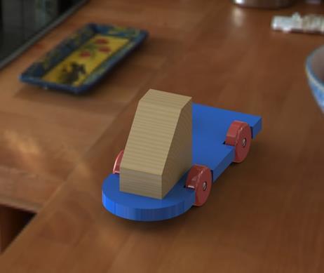
1 Introduction to SolidWorks for Technology No1: Childs Toy
2 Table of Contents Table of Contents... 1 Introduction... 2 Part Modelling: Cab... 3 Part Modelling: Base... 6 Part Modelling: Wheel Assembly: Base and Cab Assembly: Wheel Assembly using the Toolbox Completing the Assembly Creating Drawings and Worksheets PhotoView Introduction to Solidworks for Technology Page 1


3 Introduction This exercise is an introduction to SolidWorks for Technology. The exercise looks at a technology project from all areas of SolidWorks; part modelling, assembly, drawings and photoview Learning Intentions At the end of this workshop you should be able to: 1. Create new Parts using basic sketching and feature commands 2. Create a new Assembly, mating two components and adding appearances and scenes 4. Complete Drawings of an assembly including a worksheet for students 3. Create and save photorealistic images using Photoview 360 Prerequisite Knowledge None Saving Your Work Create Folder called Childs Toy. Save all files into this folder Introduction to Solidworks for Technology Page 2


4 Part Modelling: Cab Open a new part. Save Part as Cab. Create a new sketch on the Top Plane Select the Rectangle command and draw a rectangle with one corner co-incident to the origin.. Hold down the left mosue button to drag out rectangle, release when its an approximate size. Accept the sketch to complete. Introduction to Solidworks for Technology Page 3


5 Select Smart Dimension and apply the dimensions below to the rectangle. Hover over line, it will highlight in orange. Left-click on line drag out dimension line and left-click again to open the dimension window. The rectangle now turns black as it is Fully Defined sketch. Select the Features Tab and select Extruded Boss/Base The Sketch will move to an isometric view. Add 85mm dimension. Accept the extrude.. Introduction to Solidworks for Technology Page 4


6 Select the Chamfer command. It is located under the Fillet Icon. Apply a 55mm chamfer to the top edge as shown. The Full preview button will allow you to see the resulting feature. Click OK. Save your work. Apply an appearance to the Cab. Select the Appearance tab on the right. Browse for Organic, Wood, Pine. Select Polished Pine and drag and drop onto the Cab. A pop-up window will appear. Select the part icon to apply the appearance at part level. Save you work. The Cab part is now complete Introduction to Solidworks for Technology Page 5

7 Part Modelling: Base Base shape Open new Part. Save as Base. Create a sketch on the Top Plane. Draw a Corner Rectangle and dimension as shown. Select Extrude Boss/base and extrude 15mm with a blind end condition. Accept the extrude Rename the feature as Base shape (press Fn+F2) Introduction to Solidworks for Technology Page 6


8 Wheel Notches Create a new sketch on the top surface by leftclicking on the surface and selecting the sketch icon from the pop-up toolbar. Select a normal-to view by pressing the space bar and selecting Normal To Sketch two rectangles on the edge of the base as shown. The 1 st corner should have a coincident relationship with the edge of the base, as shown by the cursor having a yellow coincident relation highlighted when sketching Introduction to Solidworks for Technology Page 7
. The pop-up toolbar will allow you to add relations.")


. Click OK Save your work.")
9 Add an Equal relation to the horizontal lines (hold Ctrl key and select lines). The pop-up toolbar will allow you to add relations. Repeat the add relation for the vertical lines. The equal relations can now be seen on the lines as shown Smart Dimension black). the sketch as shown. The sketch is now full defined (sketch is now Select Extruded Cut from the features tab and change the direction to Through All Rename feature as Wheel notch (ctrl+ F2). Click OK Save your work. Introduction to Solidworks for Technology Page 8


10 Tapped Holes for Wheels Create a new Sketch on the vertical surface of the notch as shown. Draw a Centreline diagonally across the surface. Add a point to the midpoint of the centreline. Repeat this for the other notch Exit the sketch In the features tab, select Hole Wizard. The following specification is added: Type: Straight Tap Standard: ISO Hole Specification; M5 x 0.8 End Condition: Blind, depth 25mm, thread 20mm Then select Positions and select 3D Sketch Introduction to Solidworks for Technology Page 9


 and select the Front Plane as")

11 Select the two points the sketch for the position of the Hole Click OK and save Mirror the Features Select Mirror from the features tab. Open the design tree (press the + symbol beside ) and select the Front Plane as Mirror Face and the wheel notch and Tapped Hole as the Features to Mirror. Click OK Introduction to Solidworks for Technology Page 10


12 Full Round Fillet Select the Fillet feature. Select the Full Round Fillet option and select a face to enter into each of the boxes below, working left-to-right or vice versa. Click OK Add a blue high gloss plastic appearance to the part and save. The Base part is now complete Introduction to Solidworks for Technology Page 11


13 Part Modelling: Wheel Open a new part and save as Wheel. Create a sketch on the Front Plane. Using the circle command draw a circle with its centre on the origin. Smart Dimension the circle as 45mm. Extrude the circle 14mm Click OK Select the Hole wizard feature and edit the specification Hole type: Counterbore Standard: ISO Type: Pan Head Cross Recess Size: M5 End Condition: Through all Introduction to Solidworks for Technology Page 12


14 Select Positions and 3D Sketch and hover over the circle face until centre-point appears. Click on the centre to add the hole. Click OK Select the Fillet command and add a 4mm Constant Size Fillet to the front edge and click OK. Save your work Add a Red high gloss plastic appearance to the wheel The Wheel part is now complete. Introduction to Solidworks for Technology Page 13


15 Assembly: Base and Cab Create a new assembly or within the Base part select Make Assembly from Part/Assembly Insert the base part and select OK. Save as Childs Toy Assembly Select Insert Components and (Browse if not shown) click the Cab part. Use the rotate on insert tool to rotate about Y axis into the correct orientation. Click OK Introduction to Solidworks for Technology Page 14


16 Rotate the view (hold down middle mouse button) and select the bottom of the cab, on the pop-up toolbar select Mate. Select the top surface of the Base and add the coincident mate Add another coincident mate to the back of the cab and the end of the wheel notch Introduction to Solidworks for Technology Page 15


17 In the Advanced Mates tab select Width mate. In the Width made select the two sides of the cab for the width and the two sides of the base for the tab. Click OK when complete Save your work. The first part of the assembly is complete Introduction to Solidworks for Technology Page 16

18 Assembly: Wheel Assembly using the Toolbox Open a new assembly or within the wheel part select Make Assembly from Part/Assembly. This assembly will be used as a sub-assembly for the Toy. Select OK in the new assembly file. Save as Wheel Assembly Introduction to Solidworks for Technology Page 17
. Browse for ISO.")


19 Using the Toolbox. Select the Design Library tab and then the Toolbox icon. (If it is not added select Add Toolbox). Browse for ISO. Then browse for Bolts and Screws, Slotted Head Screws and select Slotted Pan Head Drag and drop screw onto screen Configure the component to the following specification Size: M5 Length: 30mm Thread Display: Schematic Click OK, then click X to accept only 1 screw Introduction to Solidworks for Technology Page 18
. You may need to flip direction. Click OK to accept mate.")

20 Mating the Wheel Parts Select the mate command and select the cylindrical surface of the screw head and the hole to add as a concentric mate (automatic). You may need to flip direction. Click OK to accept mate. Also select Lock Rotation Add a second coincident mate, selecting the back of the screw head and the inner surface of the counterbore. Accept mate and Select OK. Save your work. Introduction to Solidworks for Technology Page 19


21 Go to the toolbox and browse for Plain Washer, Regular Flat Washer..Drag and drop in a washer. Configure to a M5 washer. Accept and press X. Mate the cylindrical washer surface to the cylindrical surface of the wheel. Select Lock Rotation and add this mate. Mate the flat surface of the washer to the back of the wheel. Click OK to exit the mate command Save your work The Wheel Assembly is now complete Introduction to Solidworks for Technology Page 20


22 Completing the Assembly Insert Wheel Assembly Open the Child s Toy Assembly and select Insert Components. Select the Wheel Assembly to insert. Press the Keep Visible pin down to allow you to insert the assembly multiple times. Use the rotate on insert toll to rotate 2 wheel assemblies about the Y axis Introduction to Solidworks for Technology Page 21


23 Click OK command to finish the insert Mating the Wheels to the Base To add mates between the screw and the base, hide the wheel; press the TAB key down and hover cursor over wheel. Mates to add: Concentric: cylindrical surface of screw and Tapped hole Lock rotation Coincident Back of washer with notch surface Show the wheel again by holding down SHIFT + TAB on keyboard and hover over where wheel is. Repeat this for each wheel assembly Save your work. The Assembly is now complete Introduction to Solidworks for Technology Page 22
 arrow to move the Cab.")


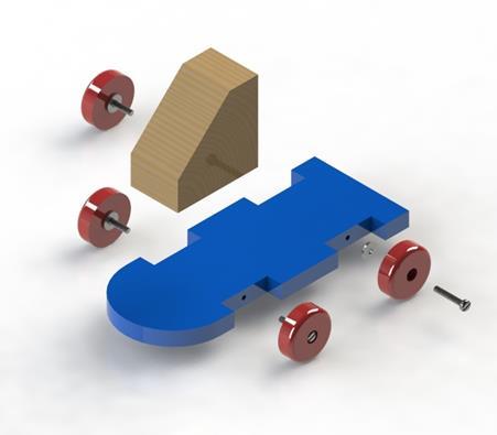
24 Creating an Exploded View Select Exploded View. Click on Cab and select Y (vertical) arrow to move the Cab. Pull the Cab upwards. When in place click anywhere away from assembly. Note this is now Explode Step 1 Select the Wheel to move next. Move along the X axis. Note how the whole wheel assembly moves Introduction to Solidworks for Technology Page 23


25 Repeat for the two far wheel assemblies To explode the wheel assembly for the last wheel, tick Select the subassembly parts. This will allow you to explode the screw, washer and wheel individually Click OK To return to the assembled view, right click on the top of the design tree and select Collapse Introduction to Solidworks for Technology Page 24


26 To explode again right click on top of design tree and select Explode To edit an exploded view, click on the ConfigurationManager tab and select the ExplView1, then select Edit Feature Childs Toy Assembly.avi Introduction to Solidworks for Technology Page 25
 In the View Palette, drag and drop the elevation by selecting Front view.")

27 Creating Drawings and Worksheets Adding Views Create a drawing from the Child s Toys Assembly Select an A3L sheet template (e.g. DCG A3L) In the View Palette, drag and drop the elevation by selecting Front view. Drag and drop the Top view for plan and Left view for end elevation. Notice how the views will auto project from elevation when dragged nearby. Change to a colour view by clicking on the view and selecting Shaded With Edges Introduction to Solidworks for Technology Page 26


28 Create the isometric View Click on the elevation and select Projected view from View Layout tab. Project out to the top lef. Hold the CTRL button down to move the isometric into the correct position. To change scale from1:2, click on view and change. Use custom scale to 1:1 Introduction to Solidworks for Technology Page 27


29 Dimension Drawing Select Model Items from Annotation tab. Select Selected Component as the Source and click on the Base in Plan. The Import items into all view is un-ticked.. Note: These dimensions are Driving dimensions imported from the parts Right click on any dimension you don t want and Hide Adjust the dimension to appear as neat as possible on the Plan Introduction to Solidworks for Technology Page 28


30 You can also add driven dimensions by clicking on Smart dimension and add dimensions manually Note: these dimensions are Driven dimensions; non-imported from parts Use the Note command to add Text Your Solution Drawing is now complete. Save your work Introduction to Solidworks for Technology Page 29


31 Detailed sheet Select Add Sheet. To add an extra view, (isometric from the front: 1. Open the assembly (use R-Key for recent documents) 2. Select the required view using the view selector cube 3. Press the SPACEBAR and click New View 4. Name the view and select OK 5. Save the file 6. Open the drawing and in the view palette refresh the views 7. Drag and drop the new view into the drawing Click on the view and select Show in exploded state To explode Add a detail view of the wheel Adjust the circle centre, radius and position of view as required Introduction to Solidworks for Technology Page 30


32 Creating worksheets Open the Base part. Open Save As. In the Design Tree select the features as shown and Delete. Select Save a copy and open. Save as Base Outline Introduction to Solidworks for Technology Page 31

 Add another")


33 In the copied part, delete the features as shown. Save the part Open the drawing (R-key) Add another sheet and add the orthographic views as before In the View Pallete browse for the Base outline part. Drag in the current isometric view Introduction to Solidworks for Technology Page 32

34 Add appropriate notes to the worksheet and save Introduction to Solidworks for Technology Page 33


35 PhotoView 360 PhotoView 360 is fully integrated into SolidWorks To add in render toolbar see Open the Childs Toy Assembly. Select the render tools tab and Render Region. Adjust the region to around the assembly Introduction to Solidworks for Technology Page 34


36 Select Final Render and allow PhotoView 360 to create the Rendered image. Save Image as Childs Toy1 Exit PhotoView 360 and open the exploded view of the assembly. Render the image as above and save as Childs Toy2 Introduction to Solidworks for Technology Page 35
Introduction to SolidWorks Basics Materials Tech. Wood
 Introduction to SolidWorks Basics Materials Tech. Wood Table of Contents Table of Contents... 1 Book End... 2 Introduction... 2 Learning Intentions... 2 Modelling the Base... 3 Modelling the Front... 10
Memo Block. This lesson includes the commands Sketch, Extruded Boss/Base, Extruded Cut, Shell, Polygon and Fillet.
 Commands Used New Part This lesson includes the commands Sketch, Extruded Boss/Base, Extruded Cut, Shell, Polygon and Fillet. Click File, New on the standard toolbar. Select Part from the New SolidWorks
SolidWorks 2009 & DCG Student Assignment
 SolidWorks 2009 & DCG Student Assignment RD10 DCG Design & Communication Graphics 1 SolidWorks 2009 & DCG Student Assignment Table of Contents Focus of the lesson. 3 Getting Started Modelling the TV Plate
SOLIDWORKS: Lesson 1 - Basics and Modeling. Introduction to Robotics
 SOLIDWORKS: Lesson 1 - Basics and Modeling Fundamentals Introduction to Robotics SolidWorks SolidWorks is a 3D solid modeling package which allows users to develop full solid models in a simulated environment
SOLIDWORKS: Lesson 1 - Basics and Modeling. UCF Engineering
 SOLIDWORKS: Lesson 1 - Basics and Modeling Fundamentals UCF Engineering SolidWorks SolidWorks is a 3D solid modeling package which allows users to develop full solid models in a simulated environment for
Battery Holder 2 x AA
 Chapter 22 JSS Battery Holder 2 x AA A. Front Extrude. Step 1. Click File Menu > New, click Part Metric and OK. Step 2. Click Front Plane in the Feature Manager and click Sketch from the Context toolbar,
Propeller. Chapter 13. Airplane. A. Base for Blade. Step 1. Click File Menu > New, click Part and OK.
 Chapter 13 Airplane Propeller A. Base for Blade. Step 1. Click File Menu > New, click Part and OK. Step 2. Click Top Plane in the Feature Manager and click Sketch toolbar, Fig. 1. from the Content Step
Body. Chapter 1. Simple Machines. A. New Part. Step 1. Click File Menu > New.
 Chapter 1 A. New Part. Step 1. Click File Menu > New. Simple Machines Body Step 2. Click Part from the list and click OK, Fig. 1. B. Sketch Construction Rectangle. Step 1. Click Right Plane in the Feature
Speedway. Body. (S) on the Sketch toolbar. Fig. 1
 on the Sketch toolbar. Fig. 1") Chapter 1 A. New Part. Step 1. Click File Menu > New. Speedway Body Step 2. Click Part from the list and click OK, Fig. 1. B. Sketch Construction Rectangle. Step 1. Click Right Plane in the Feature Manager
Chapter 1 A. New Part. Step 1. Click File Menu > New. Speedway Body Step 2. Click Part from the list and click OK, Fig. 1. B. Sketch Construction Rectangle. Step 1. Click Right Plane in the Feature Manager
Chair. Top Rail. on the Standard Views toolbar. (Ctrl-7) on the Weldments toolbar. at bottom left corner of display to deter- mine sketch plane.
 on the Weldments toolbar. at bottom left corner of display to deter- mine sketch plane.") Chapter 7 A. 3D Sketch. Step 1. If necessary, open your CHAIR file. Chair Top Rail Step 2. Click Isometric on the Standard Views toolbar. (Ctrl-7) Step 3. Zoom in around top of back leg, Fig. 1. To zoom,
Chapter 7 A. 3D Sketch. Step 1. If necessary, open your CHAIR file. Chair Top Rail Step 2. Click Isometric on the Standard Views toolbar. (Ctrl-7) Step 3. Zoom in around top of back leg, Fig. 1. To zoom,
F1 Car. Wheel. in the Feature Manager and click Sketch on the Context toolbar, Fig. 1. (S) on the
 on the") Chapter 3 F1 Car Wheel A. Sketch Lines. Step 1. Click File Menu > New, click Part Metric and OK. Step 2. Click Front Plane in the Feature Manager and click Sketch on the Context toolbar, Fig. 1. Step 3.
Chapter 3 F1 Car Wheel A. Sketch Lines. Step 1. Click File Menu > New, click Part Metric and OK. Step 2. Click Front Plane in the Feature Manager and click Sketch on the Context toolbar, Fig. 1. Step 3.
SOLIDWORKS: Lesson III Patterns & Mirrors. UCF Engineering
 SOLIDWORKS: Lesson III Patterns & Mirrors UCF Engineering Solidworks Review Last lesson we discussed several more features that can be added to models in order to increase their complexity. We are now
Boat. Battery Holder AA
 Chapter 9 Boat Battery Holder AA A. Front Extrude. Step 1. Click File Menu > New, click Part and OK. Step 2. Click Front Plane in the Feature Manager and click Sketch context toolbar, Fig. 1. Step 3. Click
Skateboard. Hanger. in the Feature Manager and click Sketch on the Context toolbar, Fig. 1. Fig. 2
 Chapter 3 Skateboard Hanger A. Sketch1 Lines. Step 1. Click File Menu > New, click Part Metric and OK. Step 2. Click Right Plane in the Feature Manager and click Sketch on the Context toolbar, Fig. 1.
Autodesk Inventor - Basics Tutorial Exercise 1
 Autodesk Inventor - Basics Tutorial Exercise 1 Launch Inventor Professional 2015 1. Start a New part. Depending on how Inventor was installed, using this icon may get you an Inch or Metric file. To be
Panel. Chapter 16. Solar Car. A. Sketch. Step 1. Click File Menu > New, click Part and OK. B. Save as "PANEL". Step 1. Click File Menu > Save As.
 Chapter 16 Solar Car Panel A. Sketch. Step 1. Click File Menu > New, click Part and OK. Step 2. Click Top Plane in the Feature Manager and click Sketch from the Content toolbar, Fig. 1. Step 3. Click Center
ME009 Engineering Graphics and Design CAD 1. 1 Create a new part. Click. New Bar. 2 Click the Tutorial tab. 3 Select the Part icon. 4 Click OK.
 PART A Reference: SolidWorks CAD Student Guide 2014 2 Lesson 2: Basic Functionality Active Learning Exercises Creating a Basic Part Use SolidWorks to create the box shown at the right. The step-by-step
Project 3. Top Down Design In Context. Below are the desired outcomes and usage competencies based upon the completion of this Project.
 Assembly Modeling with SolidWorks Project 3 Below are the desired outcomes and usage competencies based upon the completion of this Project. Project Desired Outcomes: 2AXIS-TRANSFER Assembly. PLATE-B Part.
F-1 Car. Blank. in the Feature Manager and click Sketch from the Content toolbar, Fig. 3. Origin. on the Features toolbar.
 Chapter 1 A. New Metric Part. Step 1. Click File Menu > New. F-1 Car Blank Step 2. Click Part Metric from the list of templates and click OK, Fig. 1. If you are not using SOLIDWORKS templates (you should
Solar Car. Chassis. in the Feature Manager and click Sketch from the Content toolbar, Fig. 2. Origin. on the Command Manager toolbar. Fig.
 Chapter 1 A. New Part. Step 1. Click File Menu > New. Solar Car Chassis Step 2. Click Part from the list and click OK, Fig. 1. B. Sketch Chassis. Step 1. Click Right Plane in the Feature Manager and click
Battery Holder. Chapter 9. Boat. A. Front Extrude. Step 1. Click File Menu > New, click Part and OK. SolidWorks 10 BATTERY HOLDER AA BOAT Page 9-1
 Chapter 9 Boat Battery Holder A. Front Extrude. Step 1. Click File Menu > New, click Part and OK. AA Step 2. Click Front (plane) in the Feature Manager and click Sketch from the Content toolbar, Fig. 1.
Skateboard. Hanger. in the Feature Manager and click Sketch. (S) on the Sketch. Line
 on the Sketch. Line") Chapter 3 Skateboard Hanger A. Sketch 1. Step 1. Click File Menu > New, click Part Metric and OK. Step 2. Click Right Plane from the Content toolbar, Fig. 1. in the Feature Manager and click Sketch Step
Chapter 3 Skateboard Hanger A. Sketch 1. Step 1. Click File Menu > New, click Part Metric and OK. Step 2. Click Right Plane from the Content toolbar, Fig. 1. in the Feature Manager and click Sketch Step
Autodesk Inventor Design Exercise 2: F1 Team Challenge Car Developed by Tim Varner Synergis Technologies
 Autodesk Inventor Design Exercise 2: F1 Team Challenge Car Developed by Tim Varner Synergis Technologies Tim Varner - 2004 The Inventor User Interface Command Panel Lists the commands that are currently
Simple Machines. Body. Step 4. Start at Origin and sketch the 8 lines, Fig. 2. Fig. 1. Origin
 Chapter 1 Simple Machines Body A. Sketch. Step 1. Click File Menu > New, click Part and OK. Step 2. Click Right Plane in the Feature Manager and click Sketch on the context toolbar, Fig. 1. Step 3. Click
Tail Hook. Chapter 14. Airplane. A. Construction Rectangle. Step 1. Click File Menu > New, click Part and OK.
 Chapter 14 Airplane Tail Hook A. Construction Rectangle. Step 1. Click File Menu > New, click Part and OK. Step 2. Click Right (plane) in the Feature Manager and click Sketch from the Content toolbar,
Inventor 201. Work Planes, Features & Constraints: Advanced part features and constraints
 Work Planes, Features & Constraints: 1. Select the Work Plane feature tool, move the cursor to the rim of the base so that inside and outside edges are highlighted and click once on the bottom rim of the
Blank. Chapter 1. CO2 Rail Car. A. New Metric Part. Step 1. Click File Menu > New. B. Body. Step 1. Click Right Plane
 Chapter 1 A. New Metric Part. Step 1. Click File Menu > New. CO2 Rail Car Blank Step 2. Click Part Metric from the list and click OK, Fig. 1. If you are not using SolidWorks templates (you should be),
CO 2 Shell Car. Body. in the Feature Manager and click Sketch from the context toolbar, Fig. 1. on the Standard Views toolbar.
 CO 2 Shell Car Chapter 2 Body A. Save as "BODY". Step 1. If necessary, open your BLANK file. Step 2. Click File Menu > Save As. Step 3. Key-in BODY for the filename and press ENTER. B. FRONT Wheel Shell.
Body. Chapter 2. CO2 Rail Car E. A. Save as "BODY RAIL E". Step 1. Open your BLANK file.
 Chapter 2 A. Save as "BODY RAIL E". Step 1. Open your BLANK file. Step 2. Click File Menu > Save As. Step 3. Key-in BODY RAIL E for the filename and press ENTER. CO2 Rail Car E Body B. Appearance. Step
Assembly Modeling with SolidWorks For the Intermediate SolidWorks User. David C. Planchard & Marie P. Planchard SDC PUBLICATIONS
 Supplemental Files on CD Assembly Modeling with SolidWorks 2006 For the Intermediate SolidWorks User David C. Planchard & Marie P. Planchard SDC PUBLICATIONS Schroff Development Corporation www.schroff.com
The Fundamentals of SolidWorks Featuring the VEXplorer robot with over 40 integrated stand-alone tutorials
 INSIDE: Tutorial Model Files On CD The Fundamentals of SolidWorks 2007 Featuring the VEXplorer robot with over 40 integrated stand-alone tutorials David C. Planchard & Marie P. Planchard, CSWP SDC PUBLICATIONS
CO2 Rail Car. Wheel Rear Px. on the Command Manager toolbar.
 Chapter 6 CO2 Rail Car Wheel Rear Px A. Sketch Construction Lines. Step 1. Click File Menu > New, click Part Metric and OK. Step 2. Click Front (plane) in the Feature Manager (left panel), Fig. 1. Step
Fuselage and Sharks Tooth
 Chapter 4 Glider Fuselage and Sharks Tooth A. Save as "FUSELAGE". Step 1. Open your FUSELAGE BLANK file. Step 2. Click File Menu > Save As. Step 3. Key-in FUSELAGE for the filename and press ENTER. B.
SolidWorks Implementation Guides. User Interface
 SolidWorks Implementation Guides User Interface Since most 2D CAD and SolidWorks are applications in the Microsoft Windows environment, tool buttons, toolbars, and the general appearance of the windows
SolidWorks Intro Part 1b
 SolidWorks Intro Part 1b Dave Touretzky and Susan Finger 1. Create a new part We ll create a CAD model of the 2 ½ D key fob below to make on the laser cutter. Select File New Templates IPSpart If the SolidWorks
Delta Dart. Propeller. in the Feature Manager and click Sketch from the Content toolbar, Fig. 1. on the Sketch toolbar.
 Chapter 8 Delta Dart Propeller A. Base for Blade. Step 1. Click File Menu > New, click Part Metric and OK. Step 2. Click Top Plane in the Feature Manager and click Sketch from the Content toolbar, Fig.
SOLIDWORKS 2016: A Power Guide for Beginners and Intermediate Users
 SOLIDWORKS 2016: A Power Guide for Beginners and Intermediate Users The premium provider of learning products and solutions www.cadartifex.com Table of Contents Dedication... 3 Preface... 15 Part 1. Introducing
TUTORIAL 2. OBJECTIVE: Use SolidWorks/COSMOS to model and analyze a cattle gate bracket that is subjected to a force of 100,000 lbs.
 TUTORIAL 2 OBJECTIVE: Use SolidWorks/COSMOS to model and analyze a cattle gate bracket that is subjected to a force of 100,000 lbs. GETTING STARTED: 1. Open the SolidWorks program. 2. Open a new part file.
Autodesk Fusion 360 Training: The Future of Making Things Attendee Guide
 Autodesk Fusion 360 Training: The Future of Making Things Attendee Guide Abstract After completing this workshop, you will have a basic understanding of editing 3D models using Autodesk Fusion 360 TM to
Chapter 4 Feature Design Tree
 4-1 Chapter 4 Feature Design Tree Understand Feature Interactions Use the FeatureManager Design Tree Modify and Update Feature Dimensions Perform History-Based Part Modifications Change the Names of Created
Changes from SolidWorks 2003 to SolidWorks 2004
 Changes from SolidWorks 2003 to SolidWorks 2004 The changes from SolidWorks 2003 to SolidWorks 2004 are primarily cosmetic. Consequently, it is quite easy to use the current edition of Learning SolidWorks
SOLIDWORKS 2018 Reference Guide
 SOLIDWORKS 2018 Reference Guide A comprehensive reference guide with over 250 standalone tutorials David C. Planchard, CSWP, SOLIDWORKS Accredited Educator SDC PUBLICATIONS Better Textbooks. Lower Prices.
Parametric Modeling with SOLIDWORKS 2017
 Parametric Modeling with SOLIDWORKS 2017 NEW Contains a new chapter on 3D printing Covers material found on the CSWA exam Randy H. Shih Paul J. Schilling SDC PUBLICATIONS Better Textbooks. Lower Prices.
Assembly Motion Study
 Penny Hockey Chapter 10 Assembly Motion Study A. Rename Penny Mate. Step 1. Open your PENNY HOCKEY ASSEMBLY file. Step 2. Expand Mates in the Feature Manager and select the last Mate, Fig. 1. This should
Delta Dart. Socket. (L) on the Sketch toolbar. Fig. 1. (S) on the Sketch toolbar. on the Sketch toolbar. on the Standard Views toolbar.
 on the Sketch toolbar. Fig. 1. (S) on the Sketch toolbar. on the Sketch toolbar. on the Standard Views toolbar.") Chapter 6 Delta Dart Socket A. Sketch. Step 1. Click File Menu > New, click Part Metric and OK. Step 2. Click Front Plane in the Feature Manager and click Sketch from the Content toolbar, Fig. 1. Step
Chapter 6 Delta Dart Socket A. Sketch. Step 1. Click File Menu > New, click Part Metric and OK. Step 2. Click Front Plane in the Feature Manager and click Sketch from the Content toolbar, Fig. 1. Step
Exercise Guide. Published: August MecSoft Corpotation
 VisualCAD Exercise Guide Published: August 2018 MecSoft Corpotation Copyright 1998-2018 VisualCAD 2018 Exercise Guide by Mecsoft Corporation User Notes: Contents 2 Table of Contents About this Guide 4
SolidWorks 2½D Parts
 SolidWorks 2½D Parts IDeATe Laser Micro Part 1b Dave Touretzky and Susan Finger 1. Create a new part In this lab, you ll create a CAD model of the 2 ½ D key fob below to make on the laser cutter. Select
SolidWorks Tutorial 3
 SolidWorks Tutorial Magnetic Block Preparatory Vocational Training and Advanced Vocational Training Dassault Systèmes SolidWorks Corporation, 75 Wyman Street Waltham, Massachusetts 045 USA Phone: +-800-69-9000
H Stab and V Stab. Chapter 6. Glider. A. Open and Save as "H STAB". Step 1. Open your STABILIZER BLANK file.
 Chapter 6 Glider H Stab and V Stab A. Open and Save as "H STAB". Step 1. Open your STABILIZER BLANK file. Step 2. Click File Menu > Save As. Step 3. Key-in H STAB for the filename and press ENTER. B. Sketch
Airplane Assembly. SolidWorks 10 ASSEMBLY AIRPLANE Page 9-1
 Chapter 9 A. Insert Parts. Airplane Assembly Step 1. Click File Menu > New, click Assembly and OK. Step 2. Click Keep Visible in the Property Manager, Fig. 1. Step 3. Click Browse in the Property Manager,
SolidWorks 2001 Getting Started
 SolidWorks 2001 Getting Started 1995-2001, SolidWorks Corporation 300 Baker Avenue Concord, Massachusetts 01742 USA All Rights Reserved. U.S. Patent 5,815,154 SolidWorks Corporation is a Dassault Systemes
Module 1B: Parallel-Line Flat Pattern Development of Sheet- Metal Folded Model Wrapping the 3D Space of A Truncated Right Prism
 Inventor (5) Module 1B: 1B- 1 Module 1B: Parallel-Line Flat Pattern Development of Sheet- Metal Folded Model Wrapping the 3D Space of A Truncated Right Prism In this Module, we will learn how to create
SOLIDWORKS 2016 in 5 Hours with Video Instruction
 SOLIDWORKS 2016 in 5 Hours with Video Instruction David C. Planchard, CSWP, SOLIDWORKS Accredited Educator SDC PUBLICATIONS Better Textbooks. Lower Prices. www.sdcpublications.com ACCESS CODE UNIQUE CODE
Parametric Modeling with SolidWorks
 Parametric Modeling with SolidWorks 2012 LEGO MINDSTORMS NXT Assembly Project Included Randy H. Shih Paul J. Schilling SDC PUBLICATIONS Schroff Development Corporation Better Textbooks. Lower Prices. www.sdcpublications.com
Spring Assembly. in the Begin Assembly Property. on the Standard toolbar and click Add-Ins.
 Chapter 2 Spring Assembly A. Create New Assembly. Step 1. Click File Menu > New, click Assembly and OK. Step 2. Click Cancel Manager. in the Begin Assembly Property B. Enable Toolbox Browser. Step 1. If
with Video Instruction
 SOLIDWORKS 2017 Tutorial with Video Instruction A Step-by-Step Project Based Approach Utilizing 3D Solid Modeling David C. Planchard, CSWP, SOLIDWORKS Accredited Educator SDC PUBLICATIONS Better Textbooks.
SOLIDWORKS 2017 Keyboard Modifiers & Shortcuts
 SOLIDWORKS 2017 Keyboard Modifiers & Shortcuts Copy/Paste Ctrl+C and Ctrl+V These are similar in functionality to Windows. Sketches Copies and pastes sketch entities. Part Copies and pastes sketches. Assemblies
3D Design with 123D Design
 3D Design with 123D Design Introduction: 3D Design involves thinking and creating in 3 dimensions. x, y and z axis Working with 123D Design 123D Design is a 3D design software package from Autodesk. A
SOLIDWORKS Parametric Modeling with SDC. Covers material found on the CSWA exam. Randy H. Shih Paul J. Schilling
 Parametric Modeling with SOLIDWORKS 2015 Covers material found on the CSWA exam Randy H. Shih Paul J. Schilling SDC PUBLICATIONS Better Textbooks. Lower Prices. www.sdcpublications.com Powered by TCPDF
Rocket 1. Fin. in the Feature Manager and click Sketch from the Content toolbar, Fig. 1. (L) on the Sketch toolbar. Fig. 1. Fig. 2
 on the Sketch toolbar. Fig. 1. Fig. 2") Chapter 2 Rocket 1 Fin A. Sketch. Step 1. Click File Menu > New, click Part and OK. Step 2. Click Right Plane in the Feature Manager and click Sketch from the Content toolbar, Fig. 1. Step 3. Click Line
Chapter 2 Rocket 1 Fin A. Sketch. Step 1. Click File Menu > New, click Part and OK. Step 2. Click Right Plane in the Feature Manager and click Sketch from the Content toolbar, Fig. 1. Step 3. Click Line
Solidworks 2006 Surface-modeling
 Solidworks 2006 Surface-modeling (Tutorial 2-Mouse) Surface-modeling Solid-modeling A- 1 Assembly Design Design with a Master Model Surface-modeling Tutorial 2A Import 2D outline drawing into Solidworks2006
Advanced CAD Modelling Course (SolidWorks 2009)
") Advanced CAD Modelling Course (SolidWorks 2009) Published by: The National Centre for Technology in Education And T4 Technology Subjects Support Service National Centre for Technology in Education Dublin
Advanced CAD Modelling Course (SolidWorks 2009) Published by: The National Centre for Technology in Education And T4 Technology Subjects Support Service National Centre for Technology in Education Dublin
Chapter 2 Parametric Modeling Fundamentals
 2-1 Chapter 2 Parametric Modeling Fundamentals Create Simple Extruded Solid Models Understand the Basic Parametric Modeling Procedure Create 2-D Sketches Understand the Shape before Size Approach Use the
Fig. 1. Fig. 1. on the Standard Views toolbar. SolidWorks ASSEMBLY AIRPLANE Page 8-1
 Chapter 8 Airplane Assembly A. Insert Set of Parts. Step 1. Click File Menu > New, click Assembly and OK. Step 2. Click View Menu > Origins to display the origin. Step 3. Click Keep Visible in the Property
Mastercam X6 for SolidWorks Toolpaths
 Chapter 14 Spinning Top Mastercam X6 for SolidWorks Toolpaths A. Insert Handle in New Assembly. Step 1. Click File Menu > New, click Assembly and OK. Step 2. Click Browse in the Property Manager, Fig.
SolidWorks 2013 and Engineering Graphics
 SolidWorks 2013 and Engineering Graphics An Integrated Approach Randy H. Shih SDC PUBLICATIONS Schroff Development Corporation Better Textbooks. Lower Prices. www.sdcpublications.com Visit the following
Autodesk Inventor 2016 Learn by doing. Tutorial Books
 Autodesk Inventor 2016 Learn by doing Tutorial Books Copyright 2015 Kishore This book may not be duplicated in any way without the express written consent of the publisher, except in the form of brief
e b f SOLIDWORKS ESSENTIALS 1) SOLIDWORKS USER INTERFACE SUBJECT: USER INTERFACE KEYWORDS: ESSENTIALS/ FUNDAMENTALS a) The Graphics Area
 SOLIDWORKS USER INTERFACE SUBJECT: USER INTERFACE KEYWORDS: ESSENTIALS/ FUNDAMENTALS a) The Graphics Area") SUBJECT: USER INTERFACE KEYWORDS: ESSENTIALS/ FUNDAMENTALS SOLIDWORKS ESSENTIALS The aim of this document is to provide additional reference material to allow new users of SolidWorks to navigate through
SUBJECT: USER INTERFACE KEYWORDS: ESSENTIALS/ FUNDAMENTALS SOLIDWORKS ESSENTIALS The aim of this document is to provide additional reference material to allow new users of SolidWorks to navigate through
Lesson 12 Bottom-Up Assembly Modeling
 Lesson 12 Bottom-Up Assembly Modeling Upon successful completion of this lesson, you will be able to: Create a new assembly. Insert components into an assembly using all available techniques. Add mating
3 AXIS STANDARD CAD. BobCAD-CAM Version 28 Training Workbook 3 Axis Standard CAD
 3 AXIS STANDARD CAD This tutorial explains how to create the CAD model for the Mill 3 Axis Standard demonstration file. The design process includes using the Shape Library and other wireframe functions
Photocopiable/digital resources may only be copied by the purchasing institution on a single site and for their own use ZigZag Education, 2013
 SketchUp Level of Difficulty Time Approximately 15 20 minutes Photocopiable/digital resources may only be copied by the purchasing institution on a single site and for their own use ZigZag Education, 2013
SketchUp Starting Up The first thing you must do is select a template.
 SketchUp Starting Up The first thing you must do is select a template. While there are many different ones to choose from the only real difference in them is that some have a coloured floor and a horizon
SOLIDWORKS 2016 and Engineering Graphics
 SOLIDWORKS 2016 and Engineering Graphics An Integrated Approach Randy H. Shih SDC PUBLICATIONS Better Textbooks. Lower Prices. www.sdcpublications.com Powered by TCPDF (www.tcpdf.org) Visit the following
SolidWorks 2008 Tutorial. with MultiMedia CD. A Step-by-Step Project Based Approach Utilizing 3D Solid Modeling
 INSIDE: MultiMedia CD An audio/visual presentation of the tutorial projects with MultiMedia CD A Step-by-Step Project Based Approach Utilizing 3D Solid Modeling David C. Planchard & Marie P. Planchard
Glider. Clay. Fig. 1 Side face. Step 5. In the Convert Entities Property Manager: click side face, Fig. 3 click OK twice, Fig. 3. Fig. 3.
 Chapter 9 A. Open Assembly File. Step 1. Open your GLIDER ASSEMBLY file. Glider Clay B. New Component Part. Step 1. Click Insert Menu > Component > New Part. Step 2. Click the side face of the Fuselage,
TRAINING SESSION Q3 2016
 There are 6 main topics in this training session which is focusing on 3D Import and 2D Drawing Tips and Tricks in IRONCAD. Content 3D modeling kernels... 2 3D Import... 3 Direct Face Modeling... 5 Unfold
Wheel GT-F. Chapter 5. CO2 Shell Car. A. Sketch. Step 1. Click File Menu > New, click Part Metric and OK.
 Chapter 5 CO2 Shell Car Wheel GT-F A. Sketch. Step 1. Click File Menu > New, click Part Metric and OK. Step 2. Click Front Plane in the Feature Manager and click Sketch on the context toolbar, Fig. 1.
Module 1: Basics of Solids Modeling with SolidWorks
 Module 1: Basics of Solids Modeling with SolidWorks Introduction SolidWorks is the state of the art in computer-aided design (CAD). SolidWorks represents an object in a virtual environment just as it exists
Autodesk Fusion 360: Model. Overview. Modeling techniques in Fusion 360
 Overview Modeling techniques in Fusion 360 Modeling in Fusion 360 is quite a different experience from how you would model in conventional history-based CAD software. Some users have expressed that it
Module 4B: Creating Sheet Metal Parts Enclosing The 3D Space of Right and Oblique Pyramids With The Work Surface of Derived Parts
 Inventor (5) Module 4B: 4B- 1 Module 4B: Creating Sheet Metal Parts Enclosing The 3D Space of Right and Oblique Pyramids With The Work Surface of Derived Parts In Module 4B, we will learn how to create
CO2 Car Assembly. in the Property Manager to place the part at the origin, Fig. 1. on the Assemblies toolbar. SolidWorks Assembly CO2 CAR Page 8-1
 Chapter 8 CO2 Car Assembly A. Insert Axles and Wheels. Step 1. Click File Menu > New, click Assembly Metric and OK. Step 2. Click Keep Visible in the Property Manager, Fig. 1. Step 3. Click Browse in the
Getting Started with ShowcaseChapter1:
 Chapter 1 Getting Started with ShowcaseChapter1: In this chapter, you learn the purpose of Autodesk Showcase, about its interface, and how to import geometry and adjust imported geometry. Objectives After
Simple Machines. Wheel. in the Feature Manager and click Sketch. on the Command Manager toolbar.
 Chapter 3 Simple Machines Wheel A. Wheel. Step 1. Click File Menu > New, click Part and OK. Step 2. Click Right Plane from the Content toolbar, Fig. 1. in the Feature Manager and click Sketch Step 3. Click
CHAPTER 1: SOLIDWORKS 2008 USER INTERFACE
 CHAPTER 1: SOLIDWORKS 2008 USER INTERFACE Chapter Objective SolidWorks is a design software application used to model and create 2D and 3D sketches, 3D parts and assemblies, and 2D drawings. Chapter 1
Intersecting Lamina. To complete this model you should have a working knowledge of Solidworks 2006/2009.
 Prerequisite knowledge Focus of lesson Problem To complete this model you should have a working knowledge of Solidworks 2006/2009. This lesson focuses on using SolidWorks to solve a geometrical problem.
Contains all new training videos for SolidWorks 2014 SolidWorks 2014 Tutorial with Video Instruction. Better Textbooks. Lower Prices.
 Videos Contains all new training videos for SolidWorks 2014 SolidWorks 2014 Tutorial with Video Instruction A Step-by-Step Project Based Approach Utilizing 3D Solid Modeling David C. Planchard, CSWP, SolidWorks
Chapter 1. SolidWorks Overview
 Chapter 1 SolidWorks Overview Objectives: When you complete this chapter you will: Have a good background knowledge of SolidWorks Have learnt how to start a SolidWorks session Understand the SolidWorks
Autodesk Inventor 6 Essentials Instructor Guide Chapter Four: Creating Placed Features Chapter Outline This chapter provides instruction on the follow
 Chapter Four: Creating Placed Features Chapter Outline This chapter provides instruction on the following topics and provides exercises for students to practice their skills. Day Two Topic: How to create
Glider. Wing. Top face click Sketch. on the Standard Views. (S) on the Sketch toolbar.
 on the Sketch toolbar.") Chapter 5 Glider Wing 4 Panel Tip A. Open and Save As "WING 4 PANEL". Step 1. Open your WING BLANK file. Step 2. Click File Menu > Save As. Step 3. Key-in WING 4 PANEL for the filename and press ENTER.
Chapter 5 Glider Wing 4 Panel Tip A. Open and Save As "WING 4 PANEL". Step 1. Open your WING BLANK file. Step 2. Click File Menu > Save As. Step 3. Key-in WING 4 PANEL for the filename and press ENTER.
Module 4A: Creating the 3D Model of Right and Oblique Pyramids
 Inventor (5) Module 4A: 4A- 1 Module 4A: Creating the 3D Model of Right and Oblique Pyramids In Module 4A, we will learn how to create 3D solid models of right-axis and oblique-axis pyramid (regular or
Revit Architecture 2015 Basics
 Revit Architecture 2015 Basics From the Ground Up Elise Moss Authorized Author SDC P U B L I C AT I O N S Better Textbooks. Lower Prices. www.sdcpublications.com Powered by TCPDF (www.tcpdf.org) Visit
JSS. Ping Pong Ball. in the Feature Manager and click Sketch on the Context toolbar, Fig. 1. on the Sketch toolbar.
 Chapter 18 JSS Ping Pong Ball A. Half Circle Sketch. Step 1. Click File Menu > New, click Part Metric and OK. Step 2. Click Front Plane in the Feature Manager and click Sketch on the Context toolbar, Fig.
Tutorial 1 Engraved Brass Plate R
 Getting Started With Tutorial 1 Engraved Brass Plate R4-090123 Table of Contents What is V-Carving?... 2 What the software allows you to do... 3 What file formats can be used?... 3 Getting Help... 3 Overview
CAD Tutorial 23: Exploded View
 CAD TUTORIAL 23: Exploded View CAD Tutorial 23: Exploded View Level of Difficulty Time Approximately 30 35 minutes Starter Activity It s a Race!!! Who can build a Cube the quickest: - Pupils out of Card?
Lesson 4: Assembly Basics
 4 Lesson 4: Assembly Basics Goals of This Lesson Understand how parts and assemblies are related. Create and modify the part Tutor2 and create the Tutor assembly. Tutor1 Tutor2 Tutor assembly Before Beginning
SOLIDWORKS 2018 Tutorial
 SOLIDWORKS 2018 Tutorial with Video Instruction A Step-by-Step Project Based Approach Utilizing 3D Solid Modeling David C. Planchard, CSWP, SOLIDWORKS Accredited Educator SDC P U B L I C AT I O N S Better
Nose Cone. Chapter 4. Rocket 3D Print. A. Revolve. Step 1. Click File Menu > New, click Part and OK. SOLIDWORKS 16 Nose Cone ROCKET 3D PRINT Page 4-1
 Chapter 4 Rocket 3D Print Nose Cone A. Revolve. Step 1. Click File Menu > New, click Part and OK. Step 2. Click Front Plane in the Feature Manager and click Sketch on the content toolbar, Fig. 1. Step
Designing Simple Buildings
 Designing Simple Buildings Contents Introduction 2 1. Pitched-roof Buildings 5 2. Flat-roof Buildings 25 3. Adding Doors and Windows 27 9. Windmill Sequence 45 10. Drawing Round Towers 49 11. Drawing Polygonal
EAA SOLIDWORKS University p 1/23. Keyboard Shortcuts. Hide/Show Display Pane = F8. Magnifying Glass = G. Previous View = Ctrl+Shift+Z.
 EAA SOLIDWORKS University p 1/23 Keyboard Shortcuts View - FeatureManager Tree Area = F9 View - Full Screen = F11 View - Orientation = SpaceBar View - Redraw = Ctrl+R View - Task Pane = Ctrl+F1 View -
SolidWorks 2015 User Interface
 SolidWorks 2015 User Interface SolidWorks a Dassault Systèmes Product Starting SolidWorks 1) On the desktop, double-click or from the start menu select: All Programs SOLIDWORKS 2015 SOLIDWORKS 2015. 2)