MR Advance Techniques. Vascular Imaging. Class III
|
|
|
- Geraldine Chambers
- 6 years ago
- Views:
Transcription
1 MR Advance Techniques Vascular Imaging Class III 1

2 Vascular Imaging There are several methods that can be used to evaluate the cardiovascular systems with the use of MRI. MRI will aloud to evaluate morphology and hemodynamic of the cardiovascular system
3 Conventional MRI Vascular Techniques MR Imaging techniques for vascular imaging include a number of imaging sequences based on: Spin Echo Fast Spin Echo Inversion Recovery Gradient Echo These pulse sequences are supplemented with a variety of options to enhance vascular imaging. Flow Compensation Pre-saturation bands Contrast enhance

4 Conventional MRI Vascular Techniques Flowing protons can produce either signal void or signal enhancement. They also produce contrast between vessels and the surrounding tissue.

5 Conventional MRI Vascular Techniques There two types of contrast in vascular imaging depending on the signal intensity from flowing blood: Black blood imaging Bright blood imaging
6 Black Blood Imaging Several techniques can be employed to produce images where vessels appear dark. They include: SE FSE IR (Next Class) GRE using pre-saturation pulses
7 Black Blood Imaging & SE In spin echo pulse sequence fast flowing blood will not received both 90 and 180 RF pulses. Consequently a signal void (dark signal) within the blood vessel will be produce.
 180º")
8 Black Blood Imaging & SE The use of pre-saturation band will optimize BBI in SE 90º ½ TE (20 ms) 180º
9 Black Blood Imaging & FSE These technique follows the same principle of Spin Echo but it uses several rephasing 180 to reduce scan time.


10 Black Blood Imaging & GRE When fast scan is required (GRE) Black Blood imaging can be optimized with the application of presaturation pulses. Saturation pulses will eliminate phase ghosting and provides intraluminal signal void for excellent distinction between patent and obstructed vessels. Pre-saturation band Pre-saturation band

11 1 ms 2 ms 3 ms Bright Blood Imaging Bright blood is achieved by using GRE combined with counter current flow and Flow-Comp.
12 MRA Magnetic Resonance Angiography (MRA) enhances the signal from moving spins in flowing blood and suppressing the signal from stationary spins residing tissues. When stationary tissues are suppressed, the appearance of vasculature is enhanced by increase signal from fresh spins which flow into the imaging volume and received RF excitation for first time (inflow effect).
13 Magnetic Resonance Angiography MRA There are several techniques that utilize different phenomena to increase signal from flowing spins. Time of Flight MRA (TOF-MRA) Phase Contrast MRA (PC-MRA) Contrast Enhance MRA (CE-MRA) Digital Subtraction MRA (DS-MRA)
14 Time of Flight MRA (TOF- MRA) TOF-MRA produces vascular contrast by manipulating the longitudinal magnetization of the stationary spins (Saturation). TOF-MRA uses incoherent gradient echo pulse sequences in combination with gradient moment nulling to enhance flow.
15 TOF-MRA Parameters and imaging options: TR TE Slice position Slice acquisition SAT bands MTC
16 TOF-MRA The TR is kept well bellow the T1 time of the stationary tissue so that T1 recovery is prevented. This saturates the stationary protons while the inflow effects from fully magnetized flowing fresh spins produces high vascular signal.
17 TOF MRA The TE should also be kept as low as possible to: Reduce Time of Flight effect and increase flow related enhancement Reduce intra-voxel dephasing and subsequent phase ghosting and signal loss.
18 TOF-MRA TOF-MRA is most sensitive to flow that is perpendicular to the FOV and the slice. Slices must be positioning as perpendicular as possible to the blood vessels.

19 TOF-MRA Any flow that is parallel to the slices can be saturated along with the stationary protons if their flow velocities are slow respect to the TR This phenomenon is known as in- plane flow saturation and can result in areas of signal void within the blood vessels.


20 TOF-MRA TOF-MRA must be acquired counter current flow to the blood vessel of interest to maintain the entry slice phenomenon

21 Spatial Saturation The use of pre-saturation bands in TOF-MRA is important to limit our view to either the arteries or the veins.

22 Spatial Saturation The saturation band should be placed in a the position so that it will eliminate undesired signal from flowing protons.

23 Spatial Saturation The saturation band should be placed in a the position so that it will eliminate undesired signal from flowing protons. Pre-saturation band
24 Spatial Saturation The saturation bands used in TOF-MRI are walking pre-sats.


25 MTC T1-MTC + + GAD Magnetization Transfer Contrast (MTC) is use to saturate water bound to macromolecules. If this water becomes saturated the overall background signal intensity will drop and the image will look darker (less SNR).

26 TOF-MRA A disadvantage of TOF-MRA is the high signal intensity in some background tissues, especially those with short T1 relaxation times (fat). Other tissue that may appear bright during TOF-MRA is blood components with short T1 times, such as methemoglobin. They can be a problem in distinguishing sub-acute hemorrhage from flowing blood in TOF-MRA.
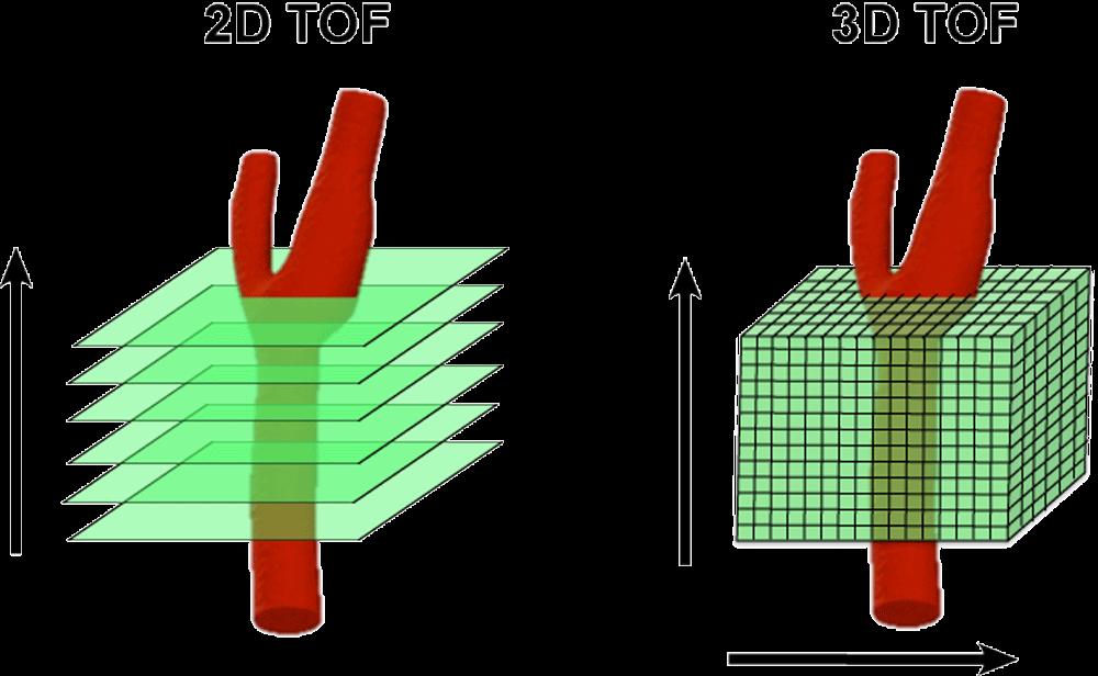
27 TOF-MRA TOF-MRA can be acquired in 2D and 3D. 2D is acquired slice by slice 3D is acquired in a volumetric acquisition
28
29 3D TOF-MRA 3D TOF-MRA offers high SNR and thin contiguous slices for good resolution. However spins in vessels with slow flow can be saturated in volume imaging.
30 3D TOF-MRA Advantages High resolution for small vessels More effective in high velocity flow areas Disadvantages Saturation of in-plane flow Small area of coverage
31 2D TOF-MRA 2D TOF is optimal in areas of: More effective in slow flow areas (carotids bifurcation, peripheral vascular and venous systems) When a large area of coverage is required 3D 2D

 Venetian")
32 2D TOF-MRA Advantages Large area of coverage More effective in slow flow areas Disadvantages Lower resolution Saturation of in-plane flow (Less than 3D) Venetian blind artifact
33 TOF-MRA Incoherent GRE (T1WI)(Minimize TOF effects) Flow Comp (Reduce intra-voxel dephasing) Slices perpendicular to the blood Vessels Counter- Current Flow (maximize entry slice) Opposite Pre-Sat (Saturate blood) MTC (Suppress Background Tissues) Very short TR to saturate stationary protons Very short TE to reduce TOF and intra voxel dephasing in flowing protons.
34 Phase Contrast MRA Phase Contrast MRA (PC-MRA) uses velocity differences, and hence the phase shifts in moving spins to provide image contrast in flowing vessels. The variation in phase originates from physiological conditions such as systolic and diastolic velocity changes. Phase shift can also be generated by a pulse sequence.

35 PC-MRA Phase shift will be achieved by the phase encoding gradient, the velocity of flow with the use of a bipolar gradient in two different acquisitions. These will create a shift difference between stationary and flowing protons.
36 PC-MRA The additional gradient used to produce the phase difference between moving spins is called velocity encoding gradient (VENC). Phase contrast MRA is sensitive to flow in any direction within the image volume. X Y Z z x y
.")
37 PC-MRA PC-MRA is sensitive to flow in three directions (X, Y, Z). The first set of image acquisition is done without the application of the VENC (Magnitude Images). Then another three sets of images are obtained each one has a VENC applied in each direction (X, Y, Z). At the end 4 sets of images are obtained (very long scan time).
38 VENC The application of the VENC is based on the velocity of the flow of the area of interest, measured in cm/sec. High venc factors of the PC angiogram (more than 40 cm/sec) will selectively image the arteries (PCA - arteriography), whereas a venc factor of 20 cm/sec will perform the veins and sinuses (PCV or MRV - venography). Blood Vessel Aorta Pulmonary Artery Superior Vena Cava Portal Vein Flow Velocity 92 cm/sec 63 cm/sec cm/sec 20 cm/sec

39 PC-MRA Phase contrast provides information about: Flow velocity Vascular anatomy Flow direction

40 PC-MRA The accumulation of flow induced phase shift is proportional to the velocity of the flow. There is direct correlation between velocity and signal intensity. More velocity more signal.
41 PC-MRA Advantages Sensitive to a variety of flow velocities Sensitive to flow within FOV Reduce intravoxel dephasing Increase background suppression Magnitude and phase images Disadvantages Long imaging times More sensitive to turbulence
42 CE-MRA A major problem with TOF MRA is that it is prone to in-plane flow (flowing protons will saturate) and the long scan times in large areas of coverage.
43 CE-MRA To overcome this, a combination of 3D imaging with IV contrast enhancement (Gadolinium) with rapid dynamic imaging may be used.
44 CE-MRA CE-MRA is a more invasive technique where a bolus injection of contrast medium is followed by a 3D Incoherent (T1WI) fast gradient echo sequence.
 TE will be reduce to the minimum (.")
45 3D-Fast Gradient Echo Very fast pulse sequence have been developed that can acquire a volume (3D) in a single breath hold. These usually employs coherent or incoherent GE. To be able to scan faster: Only one portion of the TE will be read (partial echo) TE will be reduce to the minimum (.7 ms) Only portion of the RF is applied (partial flip angle) Very short TR will be used

46 Fast Gradient Echo In addition, fast gradient echo acquisition are useful when temporal resolution is required. This is specifically important after the administration of contrast selecting fast gradient echo permits dynamic imaging of the blood vessels. Arterial phase (20 sec) Venous phase (40 sec)


47 CE-MRA This sequence is general timed to the arterial phase and the repeated several times to acquired images during intermediate and venous phases of the vascular system (Temporal Resolution or Dynamic imaging).
 Image parameters (adequate coverage, SNR, and fat")
48 Technical consideration: Injection bolus (hand injection vs power injector) Scan timing (estimating, test injection, or bolus tracking) Image parameters (adequate coverage, SNR, and fat suppression)

49 Hand Injection

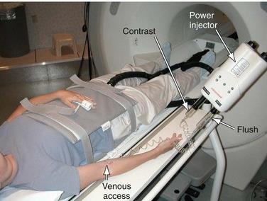
50 Power Injector

51 Bolus Detection Testing Bolus Bolus tracking Smart Prep or Fluoro-triggering


52 1 sec Testing Bolus 2 sec 20 sec after gad injection 3 sec 19 sec 20 sec 25 sec

53 On this technique the voxel Will send a signal to start Scanning Bolus Tracking

54 Live visualization of contrast, tech will Start scanning when Contrast arrives ROI
55 K-space Filling 10 sec 10 sec 10 sec If contrast take 20 sec to arrive to the ROI, and we start scanning 20 sec after injection we will be scanning the central area of the kspace around 30 seconds after contrast injection, resulting in venous contamination.

56 K-space Filling 10 sec 10 sec 10 sec If contrast take 20 sec to arrive to the ROI, and we start scanning 10 sec after injection we will be scanning the central area of the kspace around 20 seconds after contrast injection, resulting in no venous contamination.

57 Cylindrical Filling This type of filling is mostly used when image contrast and signal are required in the early phases of the examination. It is very popular in contrast enhance MRA. Scanning and injection can start at the same time, with no risk of contamination
58 Contrast Enhance MRA Advantages Sometimes it is advantageous to acquired images in the plane that best covers the anatomy. For example, to cover the ascending and descending aortic arch the Sagittal plane is optimal. Coronal plane will be a better option to visualize the abdominal aorta and the renal arteries.
59 20 SLICES Scan Time 3D=TR x PES x NEX x # Slices 40 SLICES

60 CE MRA 40 SLICES 20 SLICES
61 CE & In-plane Flow 3D 2D CE

62 2D PC MRA CE-MRV
63 Post Processing Techniques Reconstruction Techniques DS (Digital Subtraction) MIP (Maximum Intensity Projections) minip (Minimum Intensity Projections) MPR (Multi-Planar Reconstruction) Volume Rendering Shaded surface display (SSD) 63


")
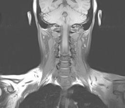
64 Digital Subtraction Digital subtraction is a technique used to remove signal from stationary protons on the image an enhance the signal from protons in blood stream. These technique can be applied with different purposes (Original + gad) Original Gad - =
 -")
65 Arterial phase (20 sec) Venous phase (40 sec) - =
66 Digital Subtraction For DS to be effective the subtracted images must have the same: FOV Slice thickness Matrix PES FES
67 DS-MRA Digital Subtraction MRA is achieved acquiring two sets of images, one during diastole and another during systole, then both images are digitally subtracted. During diastole the velocity of the flow is slower (reduce TOF Phenomenon) and images will display high signal intensity from flowing protons. During systole there is a faster flow velocity, resulting in an increases of the TOF phenomenon and high velocity signal void.

68 Cardiac Gaiting Cardiac gating monitors cardiac motion by coordinating the excitation pulse with R wave of the cardiac cycle. This achieved by using an electrical signal generated by the cardiac motion to trigger each excitation pulse.


69 DS-MRA There is indirect correlation between flow velocity and signal intensity. More velocity less signal Systole Less velocity more signal Diastole


70 Digital Subtraction MRA (DS-MRA) Digital subtraction digitally subtracted the two images to remove the signal from the stationary spins, leaving behind an image of only moving spins based on the phase they were acquired. Systole Diastole Subtraction - =
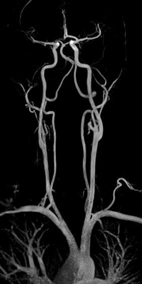
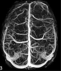
71 MIP Images that result from the TOF MRA are called source images. They are reconstructed using a mathematical algorithm call Maximum Intensity Projection (MIP) also known as Maximum intensity pixel (MIP) or Image Viewer Intensifier (IVI) Source Image 3D Image


72 MIP The maximum intensity projection algorithm is responsible for projecting the brightest pixels, from anatomical stack, to generate an image of projected view of the vessels of interest.
73


")
74 MIP is the process by 2D images (source images) are reconstructed to a 3D image.
75
76 MIP
77

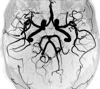
78 RT Side Posterior Circulation LT Side
79


80 CE-MRA Post Processing Digital Subtraction MRA reformats/reconstructions Maximum intensity pixel (MIP) (Plain + gad) Plain Gad MIP - =

81 Minimum Intensity Projections Minimum intensity projections (minip) use the same principle of MIP but opposite, it will make dark pixels even darker on the final image. The minimum intensity projection algorithm is responsible for projecting the darkest pixels, from anatomical stack, darker.
82 Multi-planar Reconstruction (MPR) Multi-planar reconstruction is a technique used to reconstruct images acquired in one orientation (Axial) and reconstructed in other plane (Coronal) after procedure completion. Good 3D quality is achieved by scanning with very thin slices and isotropic voxels, this combination will allow very good image quality in the reconstructed images.
83 MPR
84 Scoliosis

85 MPR (Multi Plannar Reformation)


86 3D Volume Reconstruction (Volume Rendering) Volume rendering is a technique used to display a 3D discretely sampled data set. A typical 3D data set is a group of 2D slice images acquired by a CT, MRI scanner. Usually these are acquired in a regular pattern (e.g., one slice every millimeter) and usually have a regular number of image pixels in a regular pattern.

87 Volume Rendering (VR) Volume rendering allows visualization of structures above and below the surface. Volume Rendering since it shows more than just the surface like in 3D has become the preferred method of display. Volume Rendering shows the entire scanned anatomy in 3-D like view not just the surface like a picture.
 by virtue of intensity and allows a greater range of rendering possibilities.")
88 Shaded surface display (SSD) Three-dimensional rendering requires operator-specified determination of the range of intensities that will contribute to or be eliminated from the model. The thresholding procedure removes undesirable information from the data set such as noise) by virtue of intensity and allows a greater range of rendering possibilities.
, but rather images of the surface of anatomical structures.")

89 3D Shaded Surface Display (SSD) 3D shaded surface display does not generate images of cross-sections of anatomy (cuts), but rather images of the surface of anatomical structures. The 3D images tend to look like black and white photographs of actual anatomical parts. Because they look so realistic they are used for orthopedics and planning for craniofacial surgery, neurosurgery and radiation therapy.
90 90
Magnetic Resonance Angiography
 Magnetic Resonance Angiography Course: Advance MRI (BIOE 594) Instructors: Dr Xiaohong Joe Zhou Dr. Shadi Othman By, Nayan Pasad Phase Contrast Angiography By Moran 1982, Bryan et. Al. 1984 and Moran et.
Lab Location: MRI, B2, Cardinal Carter Wing, St. Michael s Hospital, 30 Bond Street
 Lab Location: MRI, B2, Cardinal Carter Wing, St. Michael s Hospital, 30 Bond Street MRI is located in the sub basement of CC wing. From Queen or Victoria, follow the baby blue arrows and ride the CC south
Module 5: Dynamic Imaging and Phase Sharing. (true-fisp, TRICKS, CAPR, DISTAL, DISCO, HYPR) Review. Improving Temporal Resolution.
 Review. Improving Temporal Resolution.") MRES 7005 - Fast Imaging Techniques Module 5: Dynamic Imaging and Phase Sharing (true-fisp, TRICKS, CAPR, DISTAL, DISCO, HYPR) Review Improving Temporal Resolution True-FISP (I) True-FISP (II) Keyhole
MRES 7005 - Fast Imaging Techniques Module 5: Dynamic Imaging and Phase Sharing (true-fisp, TRICKS, CAPR, DISTAL, DISCO, HYPR) Review Improving Temporal Resolution True-FISP (I) True-FISP (II) Keyhole
Dynamic Contrast enhanced MRA
 Dynamic Contrast enhanced MRA Speaker: Yung-Chieh Chang Date : 106.07.22 Department of Radiology, Taichung Veterans General Hospital, Taichung, Taiwan 1 Outline Basic and advanced principles of Diffusion
Clinical Importance. Aortic Stenosis. Aortic Regurgitation. Ultrasound vs. MRI. Carotid Artery Stenosis
 Clinical Importance Rapid cardiovascular flow quantitation using sliceselective Fourier velocity encoding with spiral readouts Valve disease affects 10% of patients with heart disease in the U.S. Most
GE Healthcare CLINICAL GALLERY. Discovery * MR750w 3.0T. This brochure is intended for European healthcare professionals.
 GE Healthcare CLINICAL GALLERY Discovery * MR750w 3.0T This brochure is intended for European healthcare professionals. NEURO PROPELLER delivers high resolution, motion insensitive imaging in all planes.
White Pixel Artifact. Caused by a noise spike during acquisition Spike in K-space <--> sinusoid in image space
 White Pixel Artifact Caused by a noise spike during acquisition Spike in K-space sinusoid in image space Susceptibility Artifacts Off-resonance artifacts caused by adjacent regions with different
Outline: Contrast-enhanced MRA
 Outline: Contrast-enhanced MRA Background Technique Clinical Indications Future Directions Disclosures: GE Health Care: Research support Consultant: Bracco, Bayer The Basics During rapid IV infusion, Gadolinium
Advanced MRI Techniques (and Applications)
") Advanced MRI Techniques (and Applications) Jeffry R. Alger, PhD Department of Neurology Ahmanson-Lovelace Brain Mapping Center Brain Research Institute Jonsson Comprehensive Cancer Center University of
Advanced MRI Techniques (and Applications) Jeffry R. Alger, PhD Department of Neurology Ahmanson-Lovelace Brain Mapping Center Brain Research Institute Jonsson Comprehensive Cancer Center University of
Applications Guide for Interleaved
 Applications Guide for Interleaved rephase/dephase MRAV Authors: Yongquan Ye, Ph.D. Dongmei Wu, MS. Tested MAGNETOM Systems : 7TZ, TRIO a Tim System, Verio MR B15A (N4_VB15A_LATEST_20070519) MR B17A (N4_VB17A_LATEST_20090307_P8)
MRI. When to use What sequences. Outline 2012/09/19. Sequence: Definition. Basic Principles: Step 2. Basic Principles: Step 1. Govind Chavhan, MD
 MRI When to use What sequences Govind Chavhan, MD Assistant Professor and Staff Radiologist The Hospital For Sick Children, Toronto Planning Acquisition Post processing Interpretation Patient history and
COBRE Scan Information
 COBRE Scan Information Below is more information on the directory structure for the COBRE imaging data. Also below are the imaging parameters for each series. Directory structure: var/www/html/dropbox/1139_anonymized/human:
TOF-MRA Using Multi-Oblique-Stack Acquisition (MOSA)
") JOURNAL OF MAGNETIC RESONANCE IMAGING 26:432 436 (2007) Technical Note TOF-MRA Using Multi-Oblique-Stack Acquisition (MOSA) Ed X. Wu, PhD, 1,2 * Edward S. Hui, BEng, 1,2 and Jerry S. Cheung, BEng 1,2 Purpose:
JOURNAL OF MAGNETIC RESONANCE IMAGING 26:432 436 (2007) Technical Note TOF-MRA Using Multi-Oblique-Stack Acquisition (MOSA) Ed X. Wu, PhD, 1,2 * Edward S. Hui, BEng, 1,2 and Jerry S. Cheung, BEng 1,2 Purpose:
HST.583 Functional Magnetic Resonance Imaging: Data Acquisition and Analysis Fall 2008
 MIT OpenCourseWare http://ocw.mit.edu HST.583 Functional Magnetic Resonance Imaging: Data Acquisition and Analysis Fall 2008 For information about citing these materials or our Terms of Use, visit: http://ocw.mit.edu/terms.
CHAPTER 9: Magnetic Susceptibility Effects in High Field MRI
 Figure 1. In the brain, the gray matter has substantially more blood vessels and capillaries than white matter. The magnified image on the right displays the rich vasculature in gray matter forming porous,
Module 4. K-Space Symmetry. Review. K-Space Review. K-Space Symmetry. Partial or Fractional Echo. Half or Partial Fourier HASTE
 MRES 7005 - Fast Imaging Techniques Module 4 K-Space Symmetry Review K-Space Review K-Space Symmetry Partial or Fractional Echo Half or Partial Fourier HASTE Conditions for successful reconstruction Interpolation
MRI Physics II: Gradients, Imaging
 MRI Physics II: Gradients, Imaging Douglas C., Ph.D. Dept. of Biomedical Engineering University of Michigan, Ann Arbor Magnetic Fields in MRI B 0 The main magnetic field. Always on (0.5-7 T) Magnetizes
Slide 1. Technical Aspects of Quality Control in Magnetic Resonance Imaging. Slide 2. Annual Compliance Testing. of MRI Systems.
 Slide 1 Technical Aspects of Quality Control in Magnetic Resonance Imaging Slide 2 Compliance Testing of MRI Systems, Ph.D. Department of Radiology Henry Ford Hospital, Detroit, MI Slide 3 Compliance Testing
Diffusion MRI Acquisition. Karla Miller FMRIB Centre, University of Oxford
 Diffusion MRI Acquisition Karla Miller FMRIB Centre, University of Oxford karla@fmrib.ox.ac.uk Diffusion Imaging How is diffusion weighting achieved? How is the image acquired? What are the limitations,
HST.583 Functional Magnetic Resonance Imaging: Data Acquisition and Analysis Fall 2008
 MIT OpenCourseWare http://ocw.mit.edu HST.583 Functional Magnetic Resonance Imaging: Data Acquisition and Analysis Fall 2008 For information about citing these materials or our Terms of Use, visit: http://ocw.mit.edu/terms.
Image Acquisition Systems
 Image Acquisition Systems Goals and Terminology Conventional Radiography Axial Tomography Computer Axial Tomography (CAT) Magnetic Resonance Imaging (MRI) PET, SPECT Ultrasound Microscopy Imaging ITCS
SIEMENS MAGNETOM Verio syngo MR B15V
 \\USER\ZAHID_RESEARCH\MS\No Name\3D SWI TA: 6:39 PAT: 2 Voxel size: 1.0 0.5 2.0 mm Rel. SNR: 1.00 SIEMENS: gre Properties Prio Recon Before measurement After measurement Load to viewer Inline movie Auto
Compressed Sensing for Rapid MR Imaging
 Compressed Sensing for Rapid Imaging Michael Lustig1, Juan Santos1, David Donoho2 and John Pauly1 1 Electrical Engineering Department, Stanford University 2 Statistics Department, Stanford University rapid
Lucy Phantom MR Grid Evaluation
 Lucy Phantom MR Grid Evaluation Anil Sethi, PhD Loyola University Medical Center, Maywood, IL 60153 November 2015 I. Introduction: The MR distortion grid, used as an insert with Lucy 3D QA phantom, is
Functional MRI. Jerry Allison, Ph. D. Medical College of Georgia
 Functional MRI Jerry Allison, Ph. D. Medical College of Georgia BOLD Imaging Technique Blood Oxygen Level Dependent contrast can be used to map brain function Right Hand Motor Task Outline fmri BOLD Contrast
New Technology Allows Multiple Image Contrasts in a Single Scan
 These images were acquired with an investigational device. PD T2 T2 FLAIR T1 MAP T1 FLAIR PSIR T1 New Technology Allows Multiple Image Contrasts in a Single Scan MR exams can be time consuming. A typical
ACQUIRING AND PROCESSING SUSCEPTIBILITY WEIGHTED IMAGING (SWI) DATA ON GE 3.0T
 DATA ON GE 3.0T") ACQUIRING AND PROCESSING SUSCEPTIBILITY WEIGHTED IMAGING (SWI) DATA ON GE 3.0T Revision date: 12/13/2010 Overview Susceptibility Weighted Imaging (SWI) is a relatively new data acquisition and processing
ACQUIRING AND PROCESSING SUSCEPTIBILITY WEIGHTED IMAGING (SWI) DATA ON GE 3.0T Revision date: 12/13/2010 Overview Susceptibility Weighted Imaging (SWI) is a relatively new data acquisition and processing
(a Scrhon5 R2iwd b. P)jc%z 5. ivcr3. 1. I. ZOms Xn,s. 1E IDrAS boms. EE225E/BIOE265 Spring 2013 Principles of MRI. Assignment 8 Solutions
jc%z 5. ivcr3. 1. I. ZOms Xn,s. 1E IDrAS boms. EE225E/BIOE265 Spring 2013 Principles of MRI. Assignment 8 Solutions") EE225E/BIOE265 Spring 2013 Principles of MRI Miki Lustig Assignment 8 Solutions 1. Nishimura 7.1 P)jc%z 5 ivcr3. 1. I Due Wednesday April 10th, 2013 (a Scrhon5 R2iwd b 0 ZOms Xn,s r cx > qs 4-4 8ni6 4
EE225E/BIOE265 Spring 2013 Principles of MRI Miki Lustig Assignment 8 Solutions 1. Nishimura 7.1 P)jc%z 5 ivcr3. 1. I Due Wednesday April 10th, 2013 (a Scrhon5 R2iwd b 0 ZOms Xn,s r cx > qs 4-4 8ni6 4
HST.583 Functional Magnetic Resonance Imaging: Data Acquisition and Analysis Fall 2006
 MIT OpenCourseWare http://ocw.mit.edu HST.583 Functional Magnetic Resonance Imaging: Data Acquisition and Analysis Fall 2006 For information about citing these materials or our Terms of Use, visit: http://ocw.mit.edu/terms.
A Virtual MR Scanner for Education
 A Virtual MR Scanner for Education Hackländer T, Schalla C, Trümper A, Mertens H, Hiltner J, Cramer BM Hospitals of the University Witten/Herdecke, Department of Radiology Wuppertal, Germany Purpose A
Breast MRI Accreditation Program Clinical Image Quality Guide
 Breast MRI Accreditation Program Clinical Image Quality Guide Introduction This document provides guidance on breast MRI clinical image quality and describes the criteria used by the ACR Breast MRI Accreditation
Medical Image Processing: Image Reconstruction and 3D Renderings
 Medical Image Processing: Image Reconstruction and 3D Renderings 김보형 서울대학교컴퓨터공학부 Computer Graphics and Image Processing Lab. 2011. 3. 23 1 Computer Graphics & Image Processing Computer Graphics : Create,
surface Image reconstruction: 2D Fourier Transform
 2/1/217 Chapter 2-3 K-space Intro to k-space sampling (chap 3) Frequenc encoding and Discrete sampling (chap 2) Point Spread Function K-space properties K-space sampling principles (chap 3) Basic Contrast
Orthopedic MRI Protocols. Philips Panorama HFO
 Orthopedic MRI Protocols Philips Panorama HFO 1 2 Prepared in collaboration with Dr. John F. Feller, Medical Director of Desert Medical Imaging, Palm Springs, CA. Desert Medical Imaging will provide the
High dynamic range magnetic resonance flow imaging in the abdomen
 High dynamic range magnetic resonance flow imaging in the abdomen Christopher M. Sandino EE 367 Project Proposal 1 Motivation Time-resolved, volumetric phase-contrast magnetic resonance imaging (also known
MRI image formation 8/3/2016. Disclosure. Outlines. Chen Lin, PhD DABR 3. Indiana University School of Medicine and Indiana University Health
 MRI image formation Indiana University School of Medicine and Indiana University Health Disclosure No conflict of interest for this presentation 2 Outlines Data acquisition Spatial (Slice/Slab) selection
Patient Specific. Protocol Identification Number (PID) Must be on each individual. MRI Image
 Must be on each individual. MRI Image") MRI PROCEDURE GUIDELINES Patient Specific Protocol Identification Number (PID) Must be on each individual MRI Image [Protocol 11/04/13, Version 1.4] (Revised 09/03/2014) Page 1 of 72 Abbreviations: BH:
MRI PROCEDURE GUIDELINES Patient Specific Protocol Identification Number (PID) Must be on each individual MRI Image [Protocol 11/04/13, Version 1.4] (Revised 09/03/2014) Page 1 of 72 Abbreviations: BH:
E. Mark Haacke, PhD. The MRI Institute for Biomedical Research Detroit, Michigan Wayne State University Detroit, Michigan 48201
 E. Mark Haacke, PhD The MRI Institute for Biomedical Research Detroit, Michigan 48202 Wayne State University Detroit, Michigan 48201 Acknowledgements The testing and establishment of these protocols has
Scan Acceleration with Rapid Gradient-Echo
 Scan Acceleration with Rapid Gradient-Echo Hsiao-Wen Chung ( 鍾孝文 ), Ph.D., Professor Dept. Electrical Engineering, National Taiwan Univ. Dept. Radiology, Tri-Service General Hospital 1 of 214 The Need
SIEMENS MAGNETOM Avanto syngo MR B15
 \\USER\INVESTIGATORS\Ravi\ADNI-Subject\Localizer TA: 0:10 PAT: Voxel size: 1.9 1.5 8.0 mm Rel. SNR: 1.00 SIEMENS: gre Properties Prio Recon Before measurement After measurement Load to viewer Inline movie
SIEMENS MAGNETOM TrioTim syngo MR B17
 \\USER\KNARRGROUP\MultiBand\LavretskyMultiBand\trufi localizer 3-plane TA: 5.1 s PAT: Voxel size: 1.2 1.2 5. Rel. SNR: 1.00 SIEMENS: trufi Load to stamp Slice group 1 Slices 1 Dist. factor 20 % Phase enc.
SIEMENS MAGNETOM Avanto syngo MR B15
 \\USER\INVESTIGATORS\Ravi\ADNI-phantom\QC Phantom-Localizer TA: 0:10 PAT: Voxel size: 1.9 1.5 8.0 mm Rel. SNR: 1.00 SIEMENS: gre Properties Prio Recon Before measurement After measurement Load to viewer
Siemens AG, Healthcare Sector. syngo MR D13 0. Supplement - Parameters and image text 0.
 Siemens AG, Healthcare Sector 0 0 n.a. English Cs2 syngo Neuro Operator MR-05014 630 05/2010 01 02 Informatik, Manual D11 Cape syngo MR D13 0.0 Supplement - Parameters and image text 0. syngo MR D13 0.
Accelerated MRI Techniques: Basics of Parallel Imaging and Compressed Sensing
 Accelerated MRI Techniques: Basics of Parallel Imaging and Compressed Sensing Peng Hu, Ph.D. Associate Professor Department of Radiological Sciences PengHu@mednet.ucla.edu 310-267-6838 MRI... MRI has low
MRI Imaging Options. Frank R. Korosec, Ph.D. Departments of Radiology and Medical Physics University of Wisconsin Madison
 MRI Imaging Options Frank R. Korosec, Ph.D. Departments of Radiolog and Medical Phsics Universit of Wisconsin Madison f.korosec@hosp.wisc.edu As MR imaging becomes more developed, more imaging options
US 1.
 US 1 Sample image: Normal pancreas seen on sonogram. Looking up from abdomen toward the head of the patient. The liver is in front of the pancreas. A vein draining the spleen is behind the pancreas http://www.radiologyinfo.org/photocat/photos.cfm?image=abdo-us-pancr.jpg&&subcategory=abdomen&&stop=9
Chapter 3 Set Redundancy in Magnetic Resonance Brain Images
 16 Chapter 3 Set Redundancy in Magnetic Resonance Brain Images 3.1 MRI (magnetic resonance imaging) MRI is a technique of measuring physical structure within the human anatomy. Our proposed research focuses
XI Signal-to-Noise (SNR)
") XI Signal-to-Noise (SNR) Lecture notes by Assaf Tal n(t) t. Noise. Characterizing Noise Noise is a random signal that gets added to all of our measurements. In D it looks like this: while in D
XI Signal-to-Noise (SNR) Lecture notes by Assaf Tal n(t) t. Noise. Characterizing Noise Noise is a random signal that gets added to all of our measurements. In D it looks like this: while in D
Magnetic Resonance Elastography (MRE) of Liver Disease
 of Liver Disease") Magnetic Resonance Elastography (MRE) of Liver Disease Authored by: Jennifer Dolan Fox, PhD VirtualScopics Inc. jennifer_fox@virtualscopics.com 1-585-249-6231 1. Overview of MRE Imaging MRE is a magnetic
Magnetic Resonance Elastography (MRE) of Liver Disease Authored by: Jennifer Dolan Fox, PhD VirtualScopics Inc. jennifer_fox@virtualscopics.com 1-585-249-6231 1. Overview of MRE Imaging MRE is a magnetic
Analysis of Cerebral Blood Flow from Small Rodents
 Analysis of Cerebral Blood Flow from Small Rodents Phase Contrast Angiography of Vascular Geometry Monika Lehmpfuhl 1,2, Andre Gaudnek 3,4, Andreas Hess 3,5, Michael Sibila 3,4 1 Dep. of Electronics and
M R I Physics Course
 M R I Physics Course Multichannel Technology & Parallel Imaging Nathan Yanasak, Ph.D. Jerry Allison Ph.D. Tom Lavin, B.S. Department of Radiology Medical College of Georgia References: 1) The Physics of
Imaging Notes, Part IV
 BME 483 MRI Notes 34 page 1 Imaging Notes, Part IV Slice Selective Excitation The most common approach for dealing with the 3 rd (z) dimension is to use slice selective excitation. This is done by applying
Qualitative Comparison of Conventional and Oblique MRI for Detection of Herniated Spinal Discs
 Qualitative Comparison of Conventional and Oblique MRI for Detection of Herniated Spinal Discs Doug Dean Final Project Presentation ENGN 2500: Medical Image Analysis May 16, 2011 Outline Review of the
Computational Medical Imaging Analysis Chapter 4: Image Visualization
 Computational Medical Imaging Analysis Chapter 4: Image Visualization Jun Zhang Laboratory for Computational Medical Imaging & Data Analysis Department of Computer Science University of Kentucky Lexington,
Computational Medical Imaging Analysis
 Computational Medical Imaging Analysis Chapter 2: Image Acquisition Systems Jun Zhang Laboratory for Computational Medical Imaging & Data Analysis Department of Computer Science University of Kentucky
Role of Parallel Imaging in High Field Functional MRI
 Role of Parallel Imaging in High Field Functional MRI Douglas C. Noll & Bradley P. Sutton Department of Biomedical Engineering, University of Michigan Supported by NIH Grant DA15410 & The Whitaker Foundation
Digital Image Processing
 Digital Image Processing SPECIAL TOPICS CT IMAGES Hamid R. Rabiee Fall 2015 What is an image? 2 Are images only about visual concepts? We ve already seen that there are other kinds of image. In this lecture
CT Basics Principles of Spiral CT Dose. Always Thinking Ahead.
 1 CT Basics Principles of Spiral CT Dose 2 Who invented CT? 1963 - Alan Cormack developed a mathematical method of reconstructing images from x-ray projections Sir Godfrey Hounsfield worked for the Central
8/11/2009. Common Areas of Motion Problem. Motion Compensation Techniques and Applications. Type of Motion. What s your problem
 Common Areas of Motion Problem Motion Compensation Techniques and Applications Abdominal and cardiac imaging. Uncooperative patient, such as pediatric. Dynamic imaging and time series. Chen Lin, PhD Indiana
Motion Artifacts and Suppression in MRI At a Glance
 Motion Artifacts and Suppression in MRI At a Glance Xiaodong Zhong, PhD MR R&D Collaborations Siemens Healthcare MRI Motion Artifacts and Suppression At a Glance Outline Background Physics Common Motion
FINDING THE TRUE EDGE IN CTA
 FINDING THE TRUE EDGE IN CTA by: John A. Rumberger, PhD, MD, FACC Your patient has chest pain. The Cardiac CT Angiography shows plaque in the LAD. You adjust the viewing window trying to evaluate the stenosis
SPECIFICATIONS FOR A NEW STATE OF ART 16 SLICE ALL PURPOSE C. T. SCANNER
 SPECIFICATIONS FOR A NEW STATE OF ART 16 SLICE ALL PURPOSE C. T. SCANNER A) Scanner Design X-Ray generator and tube: 1. Scanner: Whole body spiral CT scanner (16 slices) of latest technology. 2. X-Ray
Exam 8N080 - Introduction MRI
 Exam 8N080 - Introduction MRI Friday January 23 rd 2015, 13.30-16.30h For this exam you may use an ordinary calculator (not a graphical one). In total there are 6 assignments and a total of 65 points can
CP Generalize Concepts in Abstract Multi-dimensional Image Model Component Semantics. David Clunie.
 CP-1390 - Generalize Concepts in Abstract Multi-dimensional Image Model Semantics Page 1 STATUS Date of Last Update Person Assigned Submitter Name Submission Date Assigned 2014/06/09 David Clunie mailto:dclunie@dclunie.com
Fast Imaging UCLA. Class Business. Class Business. Daniel B. Ennis, Ph.D. Magnetic Resonance Research Labs. Tuesday (3/7) from 6-9pm HW #1 HW #2
 from 6-9pm HW #1 HW #2") Fast Imaging Daniel B. Ennis, Ph.D. Magnetic Resonance Research Labs Class Business Tuesday (3/7) from 6-9pm 6:00-7:30pm Groups Avanto Sara Said, Yara Azar, April Pan Skyra Timothy Marcum, Diana Lopez,
Fast Imaging Daniel B. Ennis, Ph.D. Magnetic Resonance Research Labs Class Business Tuesday (3/7) from 6-9pm 6:00-7:30pm Groups Avanto Sara Said, Yara Azar, April Pan Skyra Timothy Marcum, Diana Lopez,
BME I5000: Biomedical Imaging
 1 Lucas Parra, CCNY BME I5000: Biomedical Imaging Lecture 4 Computed Tomography Lucas C. Parra, parra@ccny.cuny.edu some slides inspired by lecture notes of Andreas H. Hilscher at Columbia University.
SIEMENS MAGNETOM Verio syngo MR B17
 \\USER\Dr. Behrmann\routine\Ilan\ep2d_bold_PMU_resting TA: 8:06 PAT: Voxel size: 3.03.03.0 mm Rel. SNR: 1.00 USER: ep2d_bold_pmu Properties Special sat. Prio Recon System Before measurement Body After
CTA HEAD Perfusion AqONE without and with IV Contrast
 CTA HEAD Perfusion AqONE without and with IV Contrast Patient Position Adult Contrast Adult Injection Rate Supine IOML perpendicular to table top. IV: 100 ml with helical head CTA 50 ml without helical
Fast Imaging Trajectories: Non-Cartesian Sampling (1)
") Fast Imaging Trajectories: Non-Cartesian Sampling (1) M229 Advanced Topics in MRI Holden H. Wu, Ph.D. 2018.05.03 Department of Radiological Sciences David Geffen School of Medicine at UCLA Class Business
Fast Imaging Trajectories: Non-Cartesian Sampling (1) M229 Advanced Topics in MRI Holden H. Wu, Ph.D. 2018.05.03 Department of Radiological Sciences David Geffen School of Medicine at UCLA Class Business
FOREWORD TO THE SPECIAL ISSUE ON MOTION DETECTION AND COMPENSATION
 Philips J. Res. 51 (1998) 197-201 FOREWORD TO THE SPECIAL ISSUE ON MOTION DETECTION AND COMPENSATION This special issue of Philips Journalof Research includes a number of papers presented at a Philips
ADNI, ADNI_QH, SURVEY. Geometry. connection
 ADNI, ADNI_QH, SURVEY Geometry Coil selection = Head connection = d Multi coil Homogeneity correction ne FOV (mm) = 250.00 RFOV (%) = 100.00 Foldover suppression Matrix scan = 256 reconstruction = 256
Medical Image Analysis
 Computer assisted Image Analysis VT04 29 april 2004 Medical Image Analysis Lecture 10 (part 1) Xavier Tizon Medical Image Processing Medical imaging modalities XRay,, CT Ultrasound MRI PET, SPECT Generic
3D3C & 2D3D Velocity Measurements Using Magnetic Resonance Velocimetry
 3D3C & 2D3D Velocity Measurements Using Magnetic Resonance Velocimetry Sven Grundmann Center of Smart Interfaces Technische Universität Darmstadt Flughafenstrasse 19 64347 Griesheim grundmann@csi-tu-darmstadt.de
UNIVERSITY OF SOUTHAMPTON
 UNIVERSITY OF SOUTHAMPTON PHYS2007W1 SEMESTER 2 EXAMINATION 2014-2015 MEDICAL PHYSICS Duration: 120 MINS (2 hours) This paper contains 10 questions. Answer all questions in Section A and only two questions
MEDICAL IMAGE ANALYSIS
 SECOND EDITION MEDICAL IMAGE ANALYSIS ATAM P. DHAWAN g, A B IEEE Engineering in Medicine and Biology Society, Sponsor IEEE Press Series in Biomedical Engineering Metin Akay, Series Editor +IEEE IEEE PRESS
Ch. 4 Physical Principles of CT
 Ch. 4 Physical Principles of CT CLRS 408: Intro to CT Department of Radiation Sciences Review: Why CT? Solution for radiography/tomography limitations Superimposition of structures Distinguishing between
High performance MRI simulations of motion on multi-gpu systems
 Xanthis et al. Journal of Cardiovascular Magnetic Resonance 2014, 16:48 RESEARCH Open Access High performance MRI simulations of motion on multi-gpu systems Christos G Xanthis 1,2, Ioannis E Venetis 3
TOPICS 2/5/2006 8:17 PM. 2D Acquisition 3D Acquisition
 TOPICS 2/5/2006 8:17 PM 2D Acquisition 3D Acquisition 2D Acquisition Involves two main steps : Slice Selection Slice selection is accomplished by spatially saturating (single or multi slice imaging) or
Imaging Guide Pancreatic Imaging
 Imaging Guide Guide to Small Animal Pancreatic Imaging using the Vevo 2100 Imaging System Ver 1.0 Guide to Small Animal Pancreatic Imaging using the Vevo 2100 Imaging System Course Objectives: This guide
MB-EPI PCASL. Release Notes for Version February 2015
 MB-EPI PCASL Release Notes for Version 1.0 20 February 2015 1 Background High-resolution arterial spin labeling (ASL) imaging is highly desirable in both neuroscience research and clinical applications
Abbie M. Diak, PhD Loyola University Medical Center Dept. of Radiation Oncology
 Abbie M. Diak, PhD Loyola University Medical Center Dept. of Radiation Oncology Outline High Spectral and Spatial Resolution MR Imaging (HiSS) What it is How to do it Ways to use it HiSS for Radiation
T 1 MAPPING FOR DCE-MRI
 T 1 MAPPING FOR DCE-MRI A dissertation submitted to the Faculty of Medicine, University of Malaya in partial fulfillment of the requirements for the degree of Master of Medical Physics By NURUN NAJWA BINTI
Basic fmri Design and Analysis. Preprocessing
 Basic fmri Design and Analysis Preprocessing fmri Preprocessing Slice timing correction Geometric distortion correction Head motion correction Temporal filtering Intensity normalization Spatial filtering
Supplementary Information
 Supplementary Information Magnetic resonance imaging reveals functional anatomy and biomechanics of a living dragon tree Linnea Hesse 1,2,*, Tom Masselter 1,2,3, Jochen Leupold 4, Nils Spengler 5, Thomas
Vessel Explorer: a tool for quantitative measurements in CT and MR angiography
 Clinical applications Vessel Explorer: a tool for quantitative measurements in CT and MR angiography J. Oliván Bescós J. Sonnemans R. Habets J. Peters H. van den Bosch T. Leiner Healthcare Informatics/Patient
Tomographic Reconstruction
 Tomographic Reconstruction 3D Image Processing Torsten Möller Reading Gonzales + Woods, Chapter 5.11 2 Overview Physics History Reconstruction basic idea Radon transform Fourier-Slice theorem (Parallel-beam)
Supplementary Figure 1
 Supplementary Figure 1 BOLD and CBV functional maps showing EPI versus line-scanning FLASH fmri. A. Colored BOLD and CBV functional maps are shown in the highlighted window (green frame) of the raw EPI
Supplementary methods
 Supplementary methods This section provides additional technical details on the sample, the applied imaging and analysis steps and methods. Structural imaging Trained radiographers placed all participants
This exercise uses one anatomical data set (ANAT1) and two functional data sets (FUNC1 and FUNC2).
 and two functional data sets (FUNC1 and FUNC2).") Exploring Brain Anatomy This week s exercises will let you explore the anatomical organization of the brain to learn some of its basic properties, as well as the location of different structures. The human
Exploring Brain Anatomy This week s exercises will let you explore the anatomical organization of the brain to learn some of its basic properties, as well as the location of different structures. The human
Automatic Determination of Arterial Input Function for Dynamic Contrast Enhanced MRI in Tumor Assessment
 Automatic Determination of Arterial Input Function for Dynamic Contrast Enhanced MRI in Tumor Assessment Jeremy Chen, Jianhua Yao, and David Thomasson Diagnostic Radiology Department, Clinical Center,
Corso di laurea in Fisica A.A Fisica Medica 4 TC
 Corso di laurea in Fisica A.A. 2007-2008 Fisica Medica 4 TC Computed Tomography Principles 1. Projection measurement 2. Scanner systems 3. Scanning modes Basic Tomographic Principle The internal structure
EPI Data Are Acquired Serially. EPI Data Are Acquired Serially 10/23/2011. Functional Connectivity Preprocessing. fmri Preprocessing
 Functional Connectivity Preprocessing Geometric distortion Head motion Geometric distortion Head motion EPI Data Are Acquired Serially EPI Data Are Acquired Serially descending 1 EPI Data Are Acquired
LOGIQ. V2 Ultrasound. Part of LOGIQ Vision Series. Imagination at work LOGIQ is a trademark of General Electric Company.
 TM LOGIQ V2 Ultrasound Part of LOGIQ Vision Series Imagination at work The brilliance of color. The simplicity of GE. Now you can add the advanced capabilities of color Doppler to patient care with the
Volumetric Analysis of the Heart from Tagged-MRI. Introduction & Background
 Volumetric Analysis of the Heart from Tagged-MRI Dimitris Metaxas Center for Computational Biomedicine, Imaging and Modeling (CBIM) Rutgers University, New Brunswick, NJ Collaboration with Dr. Leon Axel,
INDEPENDENT COMPONENT ANALYSIS APPLIED TO fmri DATA: A GENERATIVE MODEL FOR VALIDATING RESULTS
 INDEPENDENT COMPONENT ANALYSIS APPLIED TO fmri DATA: A GENERATIVE MODEL FOR VALIDATING RESULTS V. Calhoun 1,2, T. Adali, 2 and G. Pearlson 1 1 Johns Hopkins University Division of Psychiatric Neuro-Imaging,
Lecture 6: Medical imaging and image-guided interventions
 ME 328: Medical Robotics Winter 2019 Lecture 6: Medical imaging and image-guided interventions Allison Okamura Stanford University Updates Assignment 3 Due this Thursday, Jan. 31 Note that this assignment
Initial Experience of Applying TWIST Dixon with Flexible View Sharing in Breast DCE-MRI
 Initial Experience of Applying TWIST Dixon with Flexible View Sharing in Breast DCE-MRI Yuan Le PhD 1, Hal D. Kipfer MD 1, Dominik M. Nickel PhD 2, Randall Kroeker PhD 2, Brian Dale PhD 2, Stephanie P.
SPM8 for Basic and Clinical Investigators. Preprocessing. fmri Preprocessing
 SPM8 for Basic and Clinical Investigators Preprocessing fmri Preprocessing Slice timing correction Geometric distortion correction Head motion correction Temporal filtering Intensity normalization Spatial
Fast methods for magnetic resonance angiography (MRA)
") Fast methods for magnetic resonance angiography (MRA) Bahareh Vafadar Department of Electrical and Computer Engineering A thesis presented for the degree of Doctor of Philosophy University of Canterbury,
Fast methods for magnetic resonance angiography (MRA) Bahareh Vafadar Department of Electrical and Computer Engineering A thesis presented for the degree of Doctor of Philosophy University of Canterbury,
Gradient-Echo. Spin-Echo. Echo planar. Assessment of Regional Function Assessment of Global. Parallel Imaging. Function. Steady State Imaging
 Gradient-Echo Spin-Echo James W. Goldfarb Ph.D. Department of Research and Education St. Francis Hospital Program in Biomedical Engineering SUNY Stony Brook Echo planar Assessment of Regional Function