Photo: HELUKABEL. Cable drag chains
|
|
|
- Isabella Melton
- 6 years ago
- Views:
Transcription

1 Photo: HELUKABEL Cable drag chains

2 Contents Cable drag chain systems open EasyLine EFK 1.1 page 35 MultiLine EFK 14 page 38 MultiLine EFK 18.1 page 3 MultiLine EFK 18. page 311 MultiLine EFK 35 page 31 MultiLine EFK 3 page 313 3
3 Contents MultiLine EFK 44 page 314 PowerLine EFK 5. page 315 HeavyLine EFK 6. page 316 Cable drag chain systems closed SafeLine EFK 5G page 317 SafeLine EFK 36G page
4 Please use our selection table Cables for cable drag chains which follows after the cable drag chains. a) Control cables, screened and unscreened b) Elektronic data bus cables, screened and unscreened c) Servo and motor connection cables, screened and unscreened d) Environmentally-compatible cables, screened and unscreened All cables are also in our main catalogue "Cables and Wires" Advantages: Subsequent laying of cables or changing the assignment: The chain must be opened from the inside and outside curve. Pre-assembled cables can then be inserted easily. High stability: Due to multiple and large stops. Large connecting bolts ensure better force absorbing capacity. Easy handling: Only a screwdriver is needed to open the cable carrier. Quick adjustment of the chain lengths: A simple length modification is also possible at any time in the installed condition. Fastening secured using metal inserts: The cold flow characteristics are prevented in this way. Strain relief in the chain connector: The strain relief is integrated in the chain connector. The cables are fixed using cable binders. Fastening variant using rotating chain connector: Many variants are made possible using this option. Dividers: Guarantee optimum cable routing. Can be recycled: The plastic of the chain is completely recyclable. 3


5 Drag Chain Systems to HELUKABEL GmbH Sales department Dieselstraße 8 1 D-718 Hemmingen/Germany Sender Phone Fax vk_zubehoer@helukabel.de Contact Phone Fax Inquiry No. Requirement pieces Date User parameters Installation variants 1 Moving bracket Fix bracket 3 4 outside the middle in the middle 5 6 L = Total travel, R = Radius, H = Installation hight, T = Separation, E = Distance of the conduit conveyance to the middle of the total travel Internal height: Internal width: If the inner height or width are not known: Filling mm mm Cable type Quantity Outer diameter Radius: If not known: Maximum overall height mm mm Incoming supply:: Length in the middle of the traverse path or: mm from the middle of the traverse path mm If not known: Traverse path mm Installation variants (see right) Total stroke speed m/s Speed up m/s Total stroke frequency x/h Environmental effects Tub existing yes Internal width mm no 33
6 Installation manual Cable installation in drag chains The control cables in drag chains undertake an important task for the controlling and power technique, must be good synchronized with each other in the power chain systems. Further the installation of the cables and predection tubes in the power drag chains must be conducted with great care. An efficient usage upon accurate and exact cable installation. The following basic points should be noticed: 1. Where flat and round cables are mixed in one drag tray, then these should be installed loosely next to one another. The guide stays should be installed between the cables laid side by side. Try and avoid placing different sizes of round cables next to one another. Due to the limited space relationship cables arranged one above the other, frame stays are to be installed.. The cables must be installed with guide stays, dividers or in separate hole stays so as to move freely in the drag tray guides. As free space for the cables in the guide stay should be at least 1% of the cable Ø. 3. Always ensure that the cable can follow the drag trays motions without appearing to be forced. 4. If the cables are to be installed in the drag tray in layers then it is important to check upon installation that the cables are laid in such a way that they do not block eachother when the drag tray alters direction. 5. Cables should always be installed in nonkinking and nontwisting flat position into the dray trays. The cables must be reeled down tangential from the reels or drums; the cables should not be lifted up in twisted or looping form over head. Before the installation, the cables must be laid in straight and non-twisted form on plane surface. The cables must have an additional length of at least 1% of the whole length so that these can be laid freely without twisting in drag chains. 6. In case that is not possible to lay the cables as described under â, in order to lay several multi core high flexible cables with an outer diameter < 1 mm, we recommend the use of a guiding tube, in which these cables should losely laied. This tube is than integrated into the drag system. The cross section of this tube has to be much larger as the sum of the cross sections of the cables. For the free movement of the flexible energy conduits, the guide or divider stays must be installed. energy conduit 7. In case that pressure- or hydraulic tubes are integrated in a power drag system, those should be able to expand and to shrink under alternating charges without interrupting the functionability of the drag system. 8. In order to maintain a balanced running of the drag chain it is necessary to ensure that the weight of the cables inside is divided up evenly, with the heavier cables installed on the edges and the lighter types in the middle. All cables must be securely fixed at one end of the drag chain. Thus assuring that the cores are securely fastened to one side with the other, open, side allow-ing enough slack to take up the drag chain s motion. Generally it is recommended, if possible, not to use cables with a multi layer construction, e.g. >5 cores, but to split the necessary number of conductors over several cables. If you have any further questions please call our special cable department. 34

7 EasyLine EFK 1.1 Product range: Internal height 1 mm Internal width 6-41 mm Loading side slotted on outside of radius Links per metre: 67 Chain separation: 15 mm Maximum cable diameter: 8 mm Maximum procedure path: 1 m Material: modified polyamide Unsupported length Load (kg/m) Advantages: Open cross bar: The slit cross bars on the outer radius allow easy cable installation. Due to the diagonal slit configuration, cables falling out is avoided. Wire insertion tool: The wire insertion tool allows the easy insertion of cable, wires and hoses. High stability: Multiple large stops ensure high stability, while large diameter pins provide a high strenght connection between links. Quick adaptation of the chain length: The chain can be easily modified in terms of length without the use of tools. Subsequent strain relief: Strain relief is integrated into the chain end brackets. Cable ties provide secure strain relief. Self-supporting length (m) FL g Ideal installation situation for high stresses at the limit of the max. travel parameters. In this range the chain upper run is still biased, straight or has a max. sag of 1 5 mm depending on the type of chain. FL b Satisfactory installation position for many applications working in the lower to middle range of the max. travel parameters. Depending on the chain type, the sag of the chain upper run is > 1 5 mm but less than the max. sag. If the sag is greater than FL b, the arrangement is unsuitable and should be avoided. Please choose a more stable murrplastik cable drag chain. Integrated separators: Integrated separators ensure optimal cable guiding. Recyclable: The plastic used in the chain is fully recyclable. Technical modifications are subject to change without prior notice. 35
8 EasyLine EFK 1.1 Style (order code) Configuration (order code) Radius (order code) in mm Internal width (order code) in mm External width in mm R HS HMA mm mm mm Open built-in height: HS = xr+hg+s Connecting height bottom/top: HMA = xr + HG External height of chain link: HG = 14 mm Safety: S = 1 mm Length of chain link: T = 15 mm Configuration: Style: crossbar every Standard (PA) link; w/bias 7 ESD (PA) Special version Order Number: 11 Sample order: Inside width = 6 mm, Radius = 18 mm, Configuration =, Style = Order number: Determining the chain length Moving bracket Fix bracket Length = L + x R + x T + E 1 m chain = 67 x 15 mm links outside the middle in the middle Technical modifications are subject to change without prior notice. L = Travel distance, R = Radius, I = Installation height, T = Pitch, E = Distance between entry point and middle of travel distance The fixed point of the cable drag chain should be connected in the middle of the travel distance. This arrangement gives the shortest connection between the fixed point and the moving consumer and thus the most efficient chain length. 36


9 EasyLine EFK 1.1 / Accessories Insertion aid Chamber size Type Order no. Description Pack KE 16 KE wire insertion aid 1 The wire insertion aid facilitates quick and simple installation of cables in the cable chain openings. Technical modifications are subject to change without prior notice. 37
10 MultiLine EFK 14 Product range: Internal height 14 mm Internal width 16-4 mm Loading side slotted on outside of radius Links per metre: 38 Chain separation: 6 mm Maximum cable diameter: 1 mm Maximum procedure path: max. m Material: modified polyamide Style (order code) Configuration (order code) Radius (order code) in mm Internal width (order code) in mm External width in mm R HS HMA mm mm mm Open built-in height: HS = xr+hg+s Connecting height bottom/top: HMA = xr+ HG External height of chain link: Safety: Length of chain link: HG = 1 mm SK = mm T = 6 mm Configuration: Style: crossbar every Standard (PA) link; w/bias 7 ESD (PA) Special version Order number: 14 Sample order: Inside width = 16 mm, Radius = 5 mm, Configuration =, Style = Order number: Determining the chain length Please order (per chain) chain connectors. You will automatically receive 1 with a drill-hole and 1 with a bolt. Technical modifications are subject to change without prior notice. Moving bracket outside the middle Fix bracket in the middle L = Travel distance, R = Radius, I = Installation height, T = Pitch, E = Distance between entry point and middle of travel distance Length = L + x R + x T + E 1 m chain = 38 x 6 mm links The fixed point of the cable drag chain should be connected in the middle of the travel distance. This arrangement gives the shortest connection between the fixed point and the moving consumer and thus the most efficient chain length. 38
11 MultiLine MP 18.1 Product range: Internal height 18 mm Internal width 18-7 mm Loading side slotted on outside of radius Links per metre: 3 Chain separation: 33 mm Maximum cable diameter: 15 mm Maximum procedure path: max. 3 m Material: modified polyamide Style (order code) Configuration (order code) Radius (order code) in mm Internal width (order code) in mm External width in mm R HS HMA mm mm mm Open built-in height: HS = xr+hg+s Connecting height bottom/top: HMA = xr + HG External height of chain link: HG = 3 mm Safety: S = 3 mm Length of chain link: T = 33 mm Configuration: Style: crossbar every Standard (PA) link; w/bias 7 ESD (PA) Special version Order number: 181 Sample order: Inside width = 18 mm, Radius = 8 mm, Configuration =, Style = Order number: Determining the chain length Please order (per chain) chain connectors. You will automatically receive 1 with a drill-hole and 1 with a bolt. Prices on request Technical modifications are subject to change without prior notice. Moving bracket outside the middle Fix bracket in the middle L = Travel distance, R = Radius, I = Installation height, T = Pitch, E = Distance between entry point and middle of travel distance Length = L + x R + x T + E 1 m chain = 3 x 33 mm links The fixed point of the cable drag chain should be connected in the middle of the travel distance. This arrangement gives the shortest connection between the fixed point and the moving consumer and thus the most efficient chain length. 3


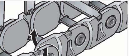

12 MultiLine MP 18.1 Assembly Step 1 Step Step 3 Disassembly Step 1 Step Technical modifications are subject to change without prior notice. 31

13 MultiLine EFK 18. Product range: Internal height 18 mm Internal width 18-7 mm Loading side slotted on outside of radius Links per metre: 3 Chain separation: 33 mm Maximum cable diameter: 15 mm Maximum procedure path: max. 3 m Material: modified polyamide Style (order code) Configuration (order code) Radius (order code) in mm Internal width (order code) in mm External width in mm R HS HMA mm mm mm Open built-in height: HS = xr+hg+s Connecting height bottom/top: HMA = xr + HG External height of chain link: HG = 3 mm Safety: S = 3 mm Length of chain link: T = 33 mm Configuration: Style: crossbar every Standard (PA) link; w/bias 7 ESD (PA) Special version Order number: 18 Sample order: Inside width = 18 mm, Radius = 8 mm, Configuration =, Style = Order number: Determining the chain length Please order (per chain) chain connectors. You will automatically receive 1 with a drill-hole and 1 with a bolt. Technical modifications are subject to change without prior notice. Moving bracket outside the middle Fix bracket in the middle L = Travel distance, R = Radius, I = Installation height, T = Pitch, E = Distance between entry point and middle of travel distance Length = L + x R + x T + E 1 m chain = 3 x 33 mm links The fixed point of the cable drag chain should be connected in the middle of the travel distance. This arrangement gives the shortest connection between the fixed point and the moving consumer and thus the most efficient chain length. 311
14 MultiLine EFK 35 Product range: Internal height 34 mm Internal width 6-15 mm Loading side slotted on outside of radius Links per metre: 17 Chain separation: 58 mm Maximum cable diameter: 3 mm Maximum procedure path: max. 8 m Material: modified polyamide Style (order code) Configuration (order code) Radius (order code) in mm Internal width (order code) in mm External width in mm R HSK HSV HMA mm mm mm mm Open built-in height without pre-tension: Open built-in height with pre-tension: Connecting height bottom/top: External height of chain link: Safety without pre-tension: Safety with pre-tension: Length of chain link: HSK = xr+hg+sk HSV = xr+hg+sv HMA = xr+ HG HG = 48 mm SK = 15 mm SV = 4 mm T = 58 mm Configuration: Style: crossbar every Standard (PA) link; w/bias 7 ESD (PA) 1 crossbar every Special version link; w/o bias Order number: 35 Sample order: Inside width = 6 mm, Radius = 7 mm, Configuration =, Style = Order number: Determining the chain length Please order (per chain) chain connectors. You will automatically receive 1 with a drill-hole and 1 with a bolt. Technical modifications are subject to change without prior notice. Moving bracket outside the middle Fix bracket in the middle L = Travel distance, R = Radius I = Installation height, T = Pitch E = Distance between entry point and middle of travel distance Length = L + x R + x T + E 1 m chain = 17 x 58 mm links The fixed point of the cable drag chain should be connected in the middle of the travel distance. This arrangement gives the shortest connection between the fixed point and the moving consumer and thus the most efficient chain length. 31
15 MultiLine EFK 3 Product range: Internal height 6 mm Internal width 6-11 mm Loading side slotted on inside of radius Links per metre: Chain separation: 45 mm Maximum cable diameter: 3 mm Maximum procedure path: max. 6 m Material: modified polyamide Style (order code) Configuration (order code) Radius (order code) in mm Internal width (order code) in mm External width in mm R HSK HSV HMA mm mm mm mm Open built-in height without pre-tension: Open built-in height with pre-tension: Connecting height bottom/top: External height of chain link: Safety without pre-tension: Safety with pre-tension: Length of chain link: HSK = xr+hg+sk HSV = xr+hg+sv HMA = xr+ HG HG = 35 mm SK = 1 mm SV = 45 mm T = 45 mm Configuration: Style: crossbar every Standard (PA) link; w/bias 7 ESD (PA) 1 crossbar every Special version link; w/o bias Order number: 3 Sample order: Inside width = 6 mm, Radius = 5 mm, Configuration =, Style = Order number: Determining the chain length Moving bracket Fix bracket Length = L + x R + x T + E Please order (per chain) chain connectors. You will automatically receive 1 with a drill-hole and 1 with a bolt. Technical modifications are subject to change without prior notice. outside the middle in the middle L = Travel distance, R = Radius, I = Installation height, T = Pitch, E = Distance between entry point and middle of travel distance 1 m chain = x 45 mm links The fixed point of the cable drag chain should be connected in the middle of the travel distance. This arrangement gives the shortest connection between the fixed point and the moving consumer and thus the most efficient chain length. 313
16 MultiLine EFK 44 Product range: Internal height 4 mm Internal width 45-4 mm Loading side slotted on outside of radius Links per metre: 13 Chain separation: 75,5 mm Maximum cable diameter: 35 mm Maximum procedure path: max. 5 m Material: modified polyamide Style (order code) Configuration (order code) Radius (order code) in mm Internal width (order code) in mm External width in mm R HSK HSV HMA mm mm mm mm Open built-in height HSK = xr+hg+sk without pre-tension: Open built-in height HSV = xr+hg+sv with pre-tension: Connecting height bottom/top: HMA = xr+hg External height of chain link: Safety without pre-tension: Safety with pre-tension: Length of chain link: HG = 6 mm SK = 13 mm SV = 38 mm T = 75,5 mm Innen ALU Configuration: Style: crossbar every Standard (PA) link; w/bias 7 ESD (PA) 1 crossbar every Special version link; w/o bias crossbar EOL; w/bias 3 crossbar EOL; w/o bias 4 AL crossbar every link; w/bias 5 AL crossbar every link; w/o bias 6 AL crossbar EOL; w/bias 7 AL crossbar EOL; w/o bias Customer order Please order (per chain) chain connectors. You will automatically receive 1 with a drill-hole and 1 with a bolt. Technical modifications are subject to change without prior notice. Order number: 44 Sample order: Inside width = 45 mm, Radius = mm, Configuration =, Style = Order number: Moving bracket outside the middle Fix bracket in the middle L = Travel distance, R = Radius I = Installation height, T = Pitch E = Distance between entry point and middle of travel distance Determining the chain length Länge = L + x R + x T + E 1 m chain = 13 x 75.5 mm links The fixed point of the cable drag chain should be connected in the middle of the travel distance. This arrangement gives the shortest connection between the fixed point and the moving consumer and thus the most efficient chain length. 314
17 PowerLine EFK 5. Product range: Internal height 5 mm Internal width mm Loading side slotted on outside of radius Links per metre: 11 Chain separation: 1 mm Maximum cable diameter: 45 mm Maximum procedure path: max. 15 m Material: modified polyamide Style (order code) Configuration (order code) Radius (order code) in mm Internal width (order code) in mm External width in mm R HSK HSV HMA mm mm mm mm Open built-in height HSK = xr+hg+sk without pre-tension: Open built-in height HSV = xr+hg+sv with pre-tension: Connecting height bottom/top: HMA = xr+hg External height of chain link: Safety without pre-tension: Safety with pre-tension: Length of chain link: HG = 74 mm SK = 16 mm SV = 46 mm T = 1 mm Innen ALU Configuration: Style: crossbar every Standard (PA) link; w/bias 7 ESD (PA) 1 crossbar every Special version link; w/o bias crossbar EOL; w/bias 3 crossbar EOL; w/o bias 4 AL crossbar every link; w/bias 5 AL crossbar every link; w/o bias 6 AL crossbar EOL; w/bias 7 AL crossbar EOL; w/o bias Customer order Please order (per chain) chain connectors. You will automatically receive 1 with a drill-hole and 1 with a bolt. Technical modifications are subject to change without prior notice. Order number: 5 Sample order: Inside width = 45 mm, Radius = 1 mm, Configuration =, Style = Order number: Moving bracket outside the middle Fix bracket in the middle L = Travel distance, R = Radius I = Installation height, T = Pitch E = Distance between entry point and middle of travel distance Determining the chain length Länge = L + x R + x T + E 1 m chain = 11 x 1 mm links The fixed point of the cable drag chain should be connected in the middle of the travel distance. This arrangement gives the shortest connection between the fixed point and the moving consumer and thus the most efficient chain length. 315
18 HeavyLine MP 6. Product range: Internal height 6 mm Internal width mm Loading side slotted on outside of radius Links per metre: 1 Chain separation: 1 mm Maximum cable diameter: 5 mm Maximum procedure path: max. 18 m Material: modified polyamide Style (order code) Configuration (order code) *= standard Radius (order code) in mm Internal width (order code) in mm External width in mm R HSK HSV HMA mm mm mm mm Open built-in height without pre-tension: Open built-in height with pre-tension: Connecting height bottom/top: External height of chain link: Safety without pre-tension: Safety with pre-tension: Length of chain link: HSK = xr+hg+sk HSV = xr+hg+sv HMA = xr+hg HG = 4 mm SK = mm SV = 5 mm T = 1 mm inside ALU Configuration: crossbar every link; w/bias 1 crossbar every link; w/o bias * crossbar EOL; w/bias 3* crossbar EOL; w/o bias 4 AL crossbar every link; w/bias 5 AL crossbar every link; w/o bias 6 AL crossbar EOL; w/bias 7 AL crossbar EOL; w/o bias Customer order Style: Standard (PA) 7 ESD (PA) Special version Please order (per chain) chain connectors. You will automatically receive 1 with a drill-hole and 1 with a bolt. Technical modifications are subject to change without prior notice. Order number: 6 Inside width = 118 mm, Radius = 15 mm, Configuration =, Style = Sample order Moving bracket outside the middle Fix bracket in the middle L = Travel distance, R = Radius, I = Installation height, T = Pitch, E = Distance between entry point and middle of travel distance Determining the chain length Length = L + x R + x T + E 1 m chain = 1 x 1 mm links The fixed point of the cable drag chain should be connected in the middle of the travel distance. This arrangement gives the shortest connection between the fixed point and the moving consumer and thus the most efficient chain length. 316
19 SafeLine EFK 5G Product range: Internal height 5 mm Internal width 6-15 mm Loading inside Links per metre: 33 Chain separation: 3 mm Maximum cable diameter: mm Maximum procedure path: max. 4 m Material: modified polyamide Style (order code) Configuration (order code) Radius (order code) in mm Internal width (order code) in mm External width in mm R HS HMA mm mm mm Open built-in height: HS = xr+hg+s Connecting height bottom/top: HMA = xr + HG External height of chain link: HG = 37 mm Safety: S = 33 mm Length of chain link: T = 3 mm Configuration: Style: crossbar every Standard (PA) link; w/bias 7 ESD (PA) Special version Order number: Sample order: Inside width = 6 mm, Radius = 6 mm, Configuration =, Style = Order number: Determining the chain length Please order (per chain) chain connectors. You will automatically receive 1 with a drill-hole and 1 with a bolt. Prices on request Technical modifications are subject to change without prior notice. Moving bracket outside the middle Fix bracket in the middle L = Travel distance, R = Radius, I = Installation height, T = Pitch, E = Distance between entry point and middle of travel distance Length = L + x R + x T + E 1 m chain = 33 x 3 mm links The fixed point of the cable drag chain should be connected in the middle of the travel distance. This arrangement gives the shortest connection between the fixed point and the moving consumer and thus the most efficient chain length. 317
20 SafeLine EFK 36G Product range: Internal height 36 mm Internal width 6-15 mm Loading inside Links per metre: 5 Chain separation: 4 mm Maximum cable diameter: 3 mm Maximum procedure path: max. 8 m Material: modified polyamide Style (order code) Configuration (order code) Radius (order code) in mm Internal width (order code) in mm External width in mm R HS HMA mm mm mm Open built-in height: HS = xr+hg+s Connecting height bottom/top: HMA = xr + HG External height of chain link: HG = 48 mm Safety: S = 3 mm Length of chain link: T = 4 mm Configuration: Style: crossbar every Standard (PA) link; w/bias 7 ESD (PA) Special version Order number: 36 Sample order: Inside width = 6 mm, Radius = 8 mm, Configuration =, Style = Order number: Determining the chain length Please order (per chain) chain connectors. You will automatically receive 1 with a drill-hole and 1 with a bolt. Prices on request Technical modifications are subject to change without prior notice. Moving bracket outside the middle Fix bracket in the middle L = Travel distance, R = Radius I = Installation height, T = Pitch E = Distance between entry point and middle of travel distance Length = L + x R + x T + E 1 m chain = 5 x 4 mm links The fixed point of the cable drag chain should be connected in the middle of the travel distance. This arrangement gives the shortest connection between the fixed point and the moving consumer and thus the most efficient chain length. 318
21 Selection table Cables in drag chains Other Technical Details can be found in the Product Pages of our Catalogue. Control Cable, screened and unscreened Type Application Cable Structure Technical Data Resistance Standards Movement Distance Min. Bending Radius Speed Accelaration Cycle Core Insulation Outher Sheath Nominal Voltage Temperature Range max. D=Outerdiameter max. max. min. in C 5 m 1 m (to 5 cores) 15 m 3 m 1 m 45 m 5 x D 7,5 x D 1 x D 1,5 x D 15 x D m/s 3 m/s 4 m/s 5 m/s 1 m/s 5 m/s 1 Mio 5 Mio 1 Mio PVC special TPE special PUR special Inner sheath Cu-braid, Cu-layer PVC special PUR special TPE special 3/3 V 3/5 V 6 V/UL-CSA 1 V halogen-free extensively oil resistant oil resistant Jacket flame veterdant microbes lye coolant radiation resistantat 8/1 Mrad uv-rays VDE-Register-No. adapted to V DE 45/81/8 UL/CSA-approved DESINA JZ-6 RC-C PUR x x x x x x x x x x x x x * * * x x x x x x x Single 6-RC-J/-O single core x x x x x x x x * * * * x x x x Single 6-RC-J/-O +CY single core x x x x x x x x x x * * * * x x x x x JZ-6 RC x x x x x x x x x * * * * x x x x x JZ-6 RC PUR x x x x x x x x x x x * * * x x x x x x x JZ-6 RC-CY x x x x x x x x x x x * * * * x x x x x JZ-HF x x x x x x x x x * * * x x x x x JZ-HF CY x x x x x x x x x x x * * * x x x x x MULTIFLEX 6 x x x x x x x x x * * * x x x x x MULTIFLEX 6-C x x x x x x x x x x x * * * x x x x x PURö-JZ-HF x x x x x x x x x x x * * * x x x x x x PURö-JZ-HF-YCP x x x x x x x x x x x x x * * * x x x x x x MULTIFLEX 51-PUR x x x x x x x x x x x x x x x * * * * * * * x x x x x x x MULTIFLEX 51-C-PUR x x x x x x x x x x x x x x x x x * * * * * * * x x x x x x x MULTIFLEX 51-PUR UL/CSA x x x x x x x x x x x x x x x * * * * * * * x x x x x x MULTIFLEX 51-C-PUR UL/CSA x x x x x x x x x x x x x x x x x * * * * * * * x x x x x x The table indicates the main application. Continuation In case of moving cables at higher speeds, over longer distances or higher cycling rates please contact our Technical Support. Phone or techsupport@helukabel.de. A cycle is a double lift: a representative sample has been tested and measurot in our Test Workshop. The cycle count is only valid when appropriatel and professionally installed (see the installation advice; rules for connections, page 34, and under permitted environment conditions). 31
22 Selection table Cables in drag chains Other Technical Details can be found in the Product Pages of our Catalogue. Control Cable, screened and unscreened Type Application Cable Structure Technical Data Resistance Standards Movement Distance Min. Bending Radius Speed Accelaration Cycle Core Insulation Outher Sheath Nominal Voltage Temperature Range max. D=Outerdiameter max. max. min. in C 5 m 1 m (to 5 cores) 15 m 3 m 1 m 45 m 5 x D 7,5 x D 1 x D 1,5 x D 15 x D m/s 3 m/s 4 m/s 5 m/s 1 m/s 5 m/s 1 Mio 5 Mio 1 Mio PVC special TPE special PUR special Inner sheath Cu-braid, Cu-layer PVC special PUR special TPE special 3/3 V 3/5 V 6 V/UL-CSA 1 V halogen-free extensively oil resistant oil resistant Jacket flame veterdant microbes lye coolant radiation resistantat 8/1 Mrad uv-rays VDE-Register-No. adapted to V DE 45/81/8 UL/CSA-approved DESINA MULTISPEED 6-PUR-J/-O x x x x x x x x x x x x x x x x x x x * * * * * * * x x x x MULTISPEED 6-C-PUR-J/-O x x x x x x x x x x x x x x x x x x x x x * * * * * * * x x x x MULTISPEED 5-PVC x x x x x x x x x x x x x x x x x * * * x x x x MULTISPEED 5-PVC UL/CSA x x x x x x x x x x x x x x x x x * * * x x x x x MULTISPEED 5-PUR x x x x x x x x x x x x x x x x x x x * * * * * * x x x x x x x MULTISPEED 5-PUR UL/CSA x x x x x x x x x x x x x x x x x x * * * * * * x x x x x x x x MULTISPEED 5-TPE x x x x x x x x x x x x x x x x x x x * * * * * * x x x x x x MULTISPEED 5-TPE UL/CSA x x x x x x x x x x x x x x x x x x x * * * * * * x x x x x x x MULTISPEED 5-C-PVC x x x x x x x x x x x x x x x x x x x * * * x x x x MULTISPEED 5-C-PVC UL/CSA x x x x x x x x x x x x x x x x x x x * * * x x x x x MULTISPEED 5-C-PUR x x x x x x x x x x x x x x x x x x x x x * * * * * * * x x x x x x x MULTISPEED 5-C-PUR UL/CSA x x x x x x x x x x x x x x x x x x x x x * * * * * * x x x x x x x x MULTISPEED 5-C-TPE x x x x x x x x x x x x x x x x x x x x x * * * * * * x x x x x x MULTISPEED 5-C-TPE UL/CSA x x x x x x x x x x x x x x x x x x x x x * * * * * * x x x x x x x The table indicates the main application. In case of moving cables at higher speeds, over longer distances or higher cycling rates please contact our Technical Support. Phone or techsupport@helukabel.de. A cycle is a double lift: a representative sample has been tested and measurot in our Test Workshop. The cycle count is only valid when appropriatel and professionally installed (see the installation advice; rules for connections, page 34, and under permitted environment conditions). 3
23 Selection table Cables in drag chains Other Technical Details can be found in the Product Pages of our Catalogue. Elektronic-Data-BUS-Cables, screened and unscreened Type Application Cable Structure Technical Data Resistance Standards Movement Distance Min. Bending Radius Speed Accelaration Cycle Core Insulation Outher Sheath Nominal Voltage Temperature Range max. D=Outerdiameter max. max. min. in C 5 m 1 m (to 5 cores) 15 m 3 m 1 m 45 m 5 x D 7,5 x D 1 x D 1,5 x D 15 x D m/s 3 m/s 4 m/s 5 m/s 1 m/s 5 m/s 1 Mio 5 Mio 1 Mio PVC special TPE special PE PUR special Inner sheath Cu-braid, Cu-layer PVC special PUR special TPE special 3/3 V 3/5 V 6 V/UL-CSA 1 V halogen-free extensively oil resistant oil resistant Jacket flame veterdant microbes lye coolant radiation resistantat 8/1 Mrad uv-rays VDE-Register-No. adapted to V DE 45/81/8 UL/CSA-approved DESINA SUPERTRONIC-PVC x x x x x x x x * * x x SUPERTRONIC-C-PVC x x x x x x x x x * * x x SUPERTRONIC 31-PVC x x x x x x x x * * * x x SUPERTRONIC 31 C-PVC x x x x x x x x x * * * x x SUPERTRONIC-PURö x x x x x x x x x x x * * x x x x SUPERTRONIC-C-PURö x x x x x x x x x x x x x x x * * * * * * * x x x x SUPERTRONIC 33 PURö x x x x x x x x x x x x x * * * * * * * x x x x SUPERTRONIC 33 C PURö x x x x x x x x x x x x x x * * * * * * * x x x x x SUPER-PAAR-TRONIC-C-PUR x x x x x x x x x x x x x x x x * * * * * * * * x x x x x SUPER-PAAR-TRONIC 34 C PUR x x x x x x x x x x x x x x x x * * * * * * * * x x x x x MULTISPEED-TRONIC-PUR x x x x x x x x x x x x x x x x x x x * * * * * x x x x x x x x MULTISPEED-TRONIC-C-PUR x x x x x x x x x x x x x x x x x x x x x * * * * * * x x x x x x x x S FTP Drag chain 4xxAWG 4 PUR x x x x x x x x x x x x x x x x * * * * * x x x PROFIBUS L1x,64 x x x x x x x x x x x * * * * * x x x x PROFIBUS CAN, high flexible x x x x x x x x x x x * * * * x x x x I-BUS Drag chain x x x x x x x x x x x * * * * x x x x POF mit PUR-Jacket, simplex duplex x x x x x x x x x x * * * * * * x x x x TOPGEBER 51 PUR x x x x x x x x x x x x x x x x x * * * * * x x x x x x x x x Tachofeedback-Cable-C-Pur x x x x x x x x x x x x x x x x * * * * * * x x x The table indicates the main application. In case of moving cables at higher speeds, over longer distances or higher cycling rates please contact our Technical Support. Phone or techsupport@helukabel.de. A cycle is a double lift: a representative sample has been tested and measurot in our Test Workshop. The cycle count is only valid when appropriatel and professionally installed (see the installation advice; rules for connections, page 34, and under permitted environment conditions). 31
24 Selection table Cables in drag chains Other Technical Details can be found in the Product Pages of our Catalogue. Servo Cables and Motor Cables, screened and unscreened Type Application Cable Structure Technical Data Resistance Standards Movement Distance Min. Bending Radius Speed Accelaration Cycle Core Insulation Outher Sheath Nominal Voltage Temperature Range max. D=Outerdiameter max. max. min. in C 5 m 1 m (to 5 cores) 15 m 3 m 1 m 45 m 5 x D 7,5 x D 1 x D 1,5 x D 15 x D m/s 3 m/s 4 m/s 5 m/s 1 m/s 5 m/s 1 Mio 5 Mio 1 Mio PVC special TPE special PUR special Inner sheath Cu-braid, Cu-layer PVC special PUR special TPE special 3/3 V 3/5 V 6 V/UL-CSA 1 V halogen-free extensively oil resistant oil resistant Jacket flame veterdant microbes lye coolant radiation resistantat 8/1 Mrad uv-rays VDE-Register-No. adapted to V DE 45/81/8 UL/CSA-approved DESINA TOPSERV 1 PUR x x x x x x x x x x x x x x x * * * * * * * x x x x x x TOPSERV 113 PUR x x x x x x x x x x x x x x * * * * * * * x x x x x x x TOPSERV 11 PUR x x x x x x x x x x x x x x * * * * * * * x x x x x x x TOPFLEX 3 x x x x x x x x * * * x x x TOPFLEX 31 x x x x x x x x x * * * * x x TOPFLEX 31 C x x x x x x x x x x * * * * x x TOPFLEX 34 x x x x x x x x x * * * x TOPFLEX 34 C x x x x x x x x x x * * * x TOPFLEX 611 PUR x x x x x x x x x x x x x x * * * * x x x TOPFLEX 611-C-PUR x x x x x x x x x x x x x x x x * * * * x x x TOPSERV 11+1 w. Control pair. screened x x x x x x x x x x x x x * * * * * * * * x x x x x x The table indicates the main application. In case of moving cables at higher speeds, over longer distances or higher cycling rates please contact our Technical Support. Phone or techsupport@helukabel.de. A cycle is a double lift: a representative sample has been tested and measurot in our Test Workshop. The cycle count is only valid when appropriatel and professionally installed (see the installation advice; rules for connections, page 34, and under permitted environment conditions). 3
25 Selection table Cables in drag chains Other Technical Details can be found in the Product Pages of our Catalogue. Environment friendly Cables, screened and unscreened Type Application Cable Structure Technical Data Resistance Standards Movement Distance Min. Bending Radius Speed Accelaration Cycle Core Insulation Outher Sheath Nominal Voltage Temperature Range max. D=Outerdiameter max. max. min. in C 5 m 1 m (to 5 cores) 15 m 3 m 1 m 45 m 5 x D 7,5 x D 1 x D 1,5 x D 15 x D m/s 3 m/s 4 m/s 5 m/s 1 m/s 5 m/s 1 Mio 5 Mio 1 Mio PVC special TPE special PUR special Inner sheath Cu-braid, Cu-layer PVC special PUR special TPE special 3/3 V 3/5 V 6 V/UL-CSA 1 V halogen-free extensively oil resistant oil resistant Jacket flame veterdant microbes lye coolant radiation resistantat 8/1 Mrad uv-rays VDE-Register-No. adapted to V DE 45/81/8 UL/CSA-approved DESINA BIOFLEX 5 JZ-HF x x x x x x x x x x x x x x * * * * * x x x x x BIOFLEX 5 JZ-HF-C x x x x x x x x x x x x x x x x * * * * * x x x x x KOMPOSPEED 6 x x x x x x x x x x x x x x * * * * * * * x x x x x x x KOMPOSPEED 6-C x x x x x x x x x x x x x x x x * * * * * * * x x x x x x KOMPOSPEED JZ-HF-5 x x x x x x x x x x x x x * * * * * * * x x x x x x KOMPOSPEED JZ-HF-C-5 x x x x x x x x x x x x x x x * * * * * * * x x x x x x Ship Cables SHIPFLEX 51 x x x x x x x x x x x x x x x * * * * * * * x x x x x SHIPFLEX 33 x x x x x x x x x x x x x x x * * * * * * * x x x x x SHIPFLEX 34 x x x x x x x x x x x x x x x * * * * * * * x x x x x SHIPFLEX 1 x x x x x x x x x x x x x x x * * * * * * * x x x x x SHIPFLEX 1 x x x x x x x x x x x x x x x * * * * * * * x x x x x SHIPFLEX 113 x x x x x x x x x x x x x x x * * * * * * * x x x x x SHIPFLEX 11 x x x x x x x x x x x x x x x * * * * * * * x x x x x The table indicates the main application. In case of moving cables at higher speeds, over longer distances or higher cycling rates please contact our Technical Support. Phone or techsupport@helukabel.de. A cycle is a double lift: a representative sample has been tested and measurot in our Test Workshop. The cycle count is only valid when appropriatel and professionally installed (see the installation advice; rules for connections, page 34, and under permitted environment conditions). 33
Cable drag chain systems MP 10.1
 Cable drag chain systems MP 10.1 1 EASYLINE MP 10.1 OPEN EASY (FILL) MECHANISM CHAIN BRACKET WITH INTEGRATED STRAIN RELIEF CAN BE EASILY SHORTENED AND LENGTHENED VERY FLEXIBLE, HIGH TORSION TECHNICAL DATA
Cable drag chain systems MP 14
 Cable drag chain systems MP 14 1 MULTILINE MP 14 OPEN LOW-COST VARIANT CHAIN BRACKET WITH INTEGRATED STRAIN RELIEF CAN BE EASILY SHORTENED AND LENGTHENED TECHNICAL DATA Loading side Outside bend Available
Screened highly flexible data transmission cable with PUR outer sheath and twisted pairs - UL/CSA-listed
 Screened highly flexible data transmission cable with PUR outer sheath and twisted pairs - UL/CSA-listed : Low-frequency PUR data cable UL AWM CMX VW-1 Halogen-free, Highly flexible Drag chain, Screened
Industrial Ethernet Cables Connectors Copper Fibre Optic Cables Accessories Assemblies Tools YOUR ONE-STOP SOLUTION PROVIDER!
 YOUR ONE-STOP SOLUTION PROVIDER! Data, Network & Bus Technology Industrial Ethernet Cables Connectors Copper Fibre Optic Cables Accessories Assemblies Tools ASSEMBLIES COPPER CABLES FIBRE OPTIC CABLES
Screened highly flexible data transmission cable with PUR outer sheath and twisted pairs - UL/CSA-listed
 Screened highly flexible data transmission cable with PUR outer sheath and twisted pairs - UL/CSA-listed : Low-frequency PUR data cable UL AWM CMX VW-1 Halogen-free, Highly flexible Drag chain, Screened
Selection BASIC LINE BASIC LINE PLUS VARIO LINE
 PLUS 196 Extremely quiet and low-vibration for highly dynamic applications* Long service life Ideal for highly dynamic applications High lateral stability Suitable for clean rooms Simple shortening and
3-pin Qualified for drag chain use Oil-resistant and flame-retardant Free from halogen, silicone, PVC and LABS culus approved
 Connection and Extension s 7/8" PUR Gray 3-pin Qualified for drag chain use Oil-resistant and flame-retardant Free from halogen, silicone, PVC and LABS culus approved Plastic, TPU, Black TPU, Black Pollution
Light, quiet all-rounder with wide range of applications* Simple divider positioning and fastening Many separation options for the cables
 A member of the TSUBAKI GROUP Light, quiet all-rounder with wide range of applications* Cost-effective cable carrier Weight-optimized chain geometry Particularly high torsional rigidity Universal Mounting
HELUKABEL YOUR ONE-STOP SOLUTION PROVIDER! Data, Network & Bus Technology. Industrial Ethernet Cables Connectors Tools Pre-assembled Parts
 HELUKABEL YOUR ONE-STOP SOLUTION PROVIDER! Data, Network & Bus Technology Industrial Ethernet Cables Connectors Tools Pre-assembled Parts ND.ETHERNET COPPER CABLE Type Application Category Item no: UL
M8, M12, 3-, 4-, 5-, 8-, 12-pin, LED, shielded
 ACCESSORIES M8, M12, 3-, 4-, 5-, 8-, 12-pin, LED, shielded ipf electronic gmbh Kalver Straße 25-27 58515 Lüdenscheid Germany Tel +49 2351 9365-0 Fax +49 2351 9365-19 111 1000 CABLE SOCKETS NOTES 112 ipf
PRODUCT INFORMATION. ETHERLINE Cat.5e FLEX. Info Industrial Ethernet cable Cat.5e Only for patch cable applications (max. 60 m)
") Ethernet cable Category 5e, Class D for flexible use - verified up to 100 MHz Industrial Ethernet cable Cat.5e for flexible use halogenfree or PUR (AWM-approval) outer sheath material, design 2 or 4 x2xawg26/7
Ethernet cable Category 5e, Class D for flexible use - verified up to 100 MHz Industrial Ethernet cable Cat.5e for flexible use halogenfree or PUR (AWM-approval) outer sheath material, design 2 or 4 x2xawg26/7
Selection table for water-resistant cables
 Just click on the products in the selection table. Click on the HELUKABEL logo at the end of the page to go back. Cables & Wires Selection table for water-resistant cables www.helukabel.com WATER-RESISTANT
PRODUCT INFORMATION. ETHERLINE Cat.5e. Info Industrial Ethernet cable Cat.5e
 Ethernet cable Category 5e, Class D for fixed installation - verified up to 100 MHz Industrial Ethernet cable Cat.5e for fixed installation halogenfree or PUR (AWM-approval) outer sheath material, design
Appendix D. EMC Installation Guidelines. Safety Considerations. Ferrite Absorbers and P-Clips. General Product Philosophy
 Appendix D EMC Installation Guidelines General Product Philosophy The ZETA6xxx was not designed originally for EMC compliance. Therefore, it will require specific measures to be taken during installation.
Complete the Installation SKINTOP MS-SC. Color Code: Approvals: Nominal Outer Diameter
 BUS UNITRONIC BUS PB For PROFIBUS-DP/FMS/FIP bus systems; stationary applications; 150 Ω UNITRONIC BUS PB UNITRONIC BUS PB FC UNITRONIC BUS PROFIBUS cables are designed for automation networks requiring
Technical data: Pin Spacing
 282 Female Connectors, Double-Row Pin Spacing: 3.5 mm Universal connection for all conductor types Unique, compact, double-row connector system for conductor cross sections up to 1.5 mm 2 High-density,
WINSTA. Full Line Catalog 2008/2009
 WINSTA Full Line Catalog 2008/2009 5 Contents FULL LINE CATALOG W4, Volume 1 Rail-Mounted Terminal Block Systems FULL LINE CATALOG W4 Rail-Mounted Terminal Blocks Volume 1 X-COM -SYSTEM Terminal Strips
07. har-link Interface Connectors
 . Interface Connectors The highest data rates in combination with perfect shielding characterize the connector. This way data can be passed on optimally within the control cabinet. The locking mechanism
english Cable Entry Systems EMC Solutions innovative creative technology Product catalogue A company of the icotek group
 english 27 Cable Entry Systems EMC Solutions innovative creative technology Product catalogue A company of the icotek group Ideas move Ideas move the world icotek GmbH is a privately held company in the
ENC 125 T/E REFERENCE MANUAL. Acu-Rite Companies Inc.
 ENC 125 T/E REFERENCE MANUAL Acu-Rite Companies Inc. ENC 125 T/E Page Introduction... 2 Mounting Preparation... 3 Mounting Information... 4 Encoder Dimensions - ENC 125 T (top mount)... 5 Encoder Dimensions
PHOENIX CONTACT Pin. SUBCON-PLUS M ARCNET, MULTI/MININET (B&R), SYSTEM 2003 (B&R), P-NET SUCONET K1, K2 (EATON/Moeller),
, SYSTEM 2003 (B&R), P-NET SUCONET K1, K2 (EATON/Moeller),") Fast connector with screw terminal block connection for fieldbus systems Data sheet 00287_en_02 PHOENIX CONTACT 207-04-2 Description The SUBCON-PLUS/... D-SUB series is specifically designed for use in
Fast connector with screw terminal block connection for fieldbus systems Data sheet 00287_en_02 PHOENIX CONTACT 207-04-2 Description The SUBCON-PLUS/... D-SUB series is specifically designed for use in
SAC-5P-MS/ 1,0-920/FS SCO
 Extract from the online catalog SAC-5P-MS/ 1,0-920/FS SCO Order No.: 1518274 Bus system cable, DeviceNet/CANOpen, 5 pos., PUR halogen-free violet, shielded, straight M12 SPEEDCON connector on straight
Electrical Interconnection
 Electrical Interconnection Edition 208/ Rail-Mount Terminal Block Systems Full Line Catalog, Volume Edition 207/208 PCB Terminal Blocks and Connectors Full Line Catalog, Volume 2 Edition 207/208 2 Automation
UNIFLEX 1455/1555 Lighter, quieter, more effective.
 UNIFLEX 1455/1555 Lighter, quieter, more effective. INNOVATIONS Lighter, quieter, 2007 more effective. The new generation: UNIFLEX 1455/1555. Lighter, quieter, more effective. New generation new designation
DESINA installation technology
 DEcentralized Standardized INstAllation technology DESINA describes an extensive concept for the standardization and decentralization of the fluid power and electrical installation of machines and applications.
SUNCLIX Connection technology for photovoltaics
 SUNCLIX Connection technology for photovoltaics Connection technology for photovoltaics Are you looking for innovative and reliable connection technology for your PV modules, inverters or the complete
SPECIAL CABLES TEMPERATURE MEASUREMENT HARNESSING USB 2.0 / 3.0 CABLES. Kuka
 SPECIAL CABLES TEMPERATURE MEASUREMENT HARNESSING USB 2.0 / 3.0 CABLES Kuka CONTENT OVERVIEW Who we are................................................................................................................
Acids- and alkali resistance. Drag-chain capability Torsion capability. Building installations Wind power plants Flame-retardant Oil resistance
 S2800 DeviceNet S1800 PROFIBUS Cat6A S4031 Ind. Ethernet Cat6A S4030 Ind. Ethernet Cat5e Cat7 Cat5 Cat5e PTFE S2430 HT TPE PVC PVC S3800 Sercos S3500 Ind. Ethernet S3400 EtherCAT S2171 S5015 S5025 POWER
Level sensor Stainless steel version Model RLT-1000, for industrial applications
 Level measurement Level sensor Stainless steel version Model RLT-1000, for industrial applications WIKA data sheet LM 50.02 Applications Level measurement of liquids in machine building Control and monitoring
ALPHA Small Distribution Boards SIMBOX 63/SIMBOX WP
 ALPHA Small Distribution Boards SIMBOX 63/SIMBOX WP SIMBOX 63 /4 Introduction /5 Flush mounting distribution boards /6 Hollow-wall distribution boards /7 Surface mounting distribution boards /7 Hood-type
CABLE ENTRY SYSTEM KDSClick
 CABLE ENTRY SYSTEM KDSClick PRODUCT INFORMATION Cable entry system KDSClick CONTA-CONNECT TURNING CABLES INSIDE OUT! a revolutionary cable entry system! Fast. Safe. Very simple. Our KDSClick cable entry
Selection can be made from different capacities (ranging from 100kN to 2000kN) from HL 590 / HL590 (FL) series or HLC 591 / HLC 591 (FL) series.
 from HL 590 / HL590 (FL) series or HLC 591 / HLC 591 (FL) series.") Universal Testing Machines UNIVERSAL TESTING MACHINE HEICO UTM is suitable to conduct following tests - (i) Compression (ii) Tension (iii) Transverse (iv)bending (v) Shear (vi) Hardness and many others
Universal Testing Machines UNIVERSAL TESTING MACHINE HEICO UTM is suitable to conduct following tests - (i) Compression (ii) Tension (iii) Transverse (iv)bending (v) Shear (vi) Hardness and many others
PCB Keyswitches Product Survey Versions Recommended Key grid Illumination Keyswitch Signal indicator Keyswitch height Contacts RACON 8 12 mm Non-illum
 PCB Keyswitches Page RACON short-travel keyswitches - 5 RACON 8-6 RACON 12-10 RACON 12 V with vertical adapter - 1 RACON 12 i - 16 RACON special accessories - 20 RF short-travel keyswitches - 23 RF 15
ME PLC Multifunctional housing for complex electronics. Data sheet _en_01. 1 Description
 Multifunctional housing for complex electronics Data sheet 105504_en_01 PHOENIX CONTACT 2013-04-08 1 Description The housings of the ME PLC 40... product group consist of a 40-mm wide housing base with
Accessories Fieldbus Box
 Power cables, sensor cables, connection cables and further accessories see the EtherCAT Box chapter from page 514 Pre-assembled cables for fieldbus components include a wide range of cable assemblies.
02)-D-EU-TWISTER-KOMPLETT- G :54 Uhr Seite
-D-EU-TWISTER-KOMPLETT- G :54 Uhr Seite") 2.104 twisterband Rotary motions in a small spaces 2.105 NEW in this catalog twisterband: compact, modular and cost-effective Rotary movements in minimum space - 20 times around its own axis With the very
2.104 twisterband Rotary motions in a small spaces 2.105 NEW in this catalog twisterband: compact, modular and cost-effective Rotary movements in minimum space - 20 times around its own axis With the very
Extract from new. Device Connectivity catalogue. HARTING har-flex. People Power Partnership
 Extract from new Device Connectivity catalogue HARTING har-flex People Power Partnership . har-flex CONNECTORS The continuous scalability by an even number of contacts, i.e. from 6 to 100, of the HARTING
6000 Series Buccaneer
 Robust, instant connections for harsh environments 6000 Series Buccaneer - circular connectors that combine the ease of use of a push/pull coupling mechanism with proven environmental sealing. Available
VF CNM5MM-L100. Accessories. M12 male connectors. Code structure. M 12x1
 Accessories M male connectors These standard M male connectors are ready for the installation on the switches. Their wires have the right length for the connection to the contact blocks and are provided
onlinecomponents.com
 0.9 For FPC FPC connectors (0.3mm pitch) Back lock Y3B Series New FEATURES 1. Slim and low profile design (Pitch: 0.3 mm) The use of a back lock mechanism enables a 3.15 mm (with lever) low profile design.
TRAY CABLES FOR INDUSTRIAL PLANT INSTALLATIONS THE RIGHT SOLUTION FOR EVERY APPLICATION
 TRAY ABLES FOR INDUSTRIAL PLANT INSTALLATIONS THE RIGHT SOLUTION FOR EVERY APPLIATION FLEXIBLE ONTROL ONTINUOUS FLEX SILIONE TORSION TRAY VFD DATA SERVO MOTOR EUROPEAN STYLE BUS/AT HALOGEN-FREE REELING
UNIVERSAL TESTING MACHINE
 Universal Testing Machines UNIVERSAL TESTING MACHINE HEICO UTM is suitable to conduct following tests (i) Compression (ii) Tension (iii) Transverse (iv)bending (v) Shear (vi) Hardness and many others on
english Cable Entry Systems EMC Solutions innovative creative technology Product program A company of the icotek group
 english 26 Cable Entry Systems EMC Solutions innovative creative technology Product program A company of the icotek group Customer requests and our constant involvement in ever changing markets is motivation
BVS UR E Ordering code: BVS001H
 BVS UR-3-101-E Ordering code: BVS001H Vision sensor BVS-E Universal PNP (2x) 1) Teach reference image, 2) Power, 3) Output 1 active, 4) Output 2 active, 5) Connection with PC, 6) Sharpness Characteristic
FiberConnect FiberTech FiberSwitch FiberSplit
 FiberConnect FiberTech FiberSwitch FiberSplit 71 Simplex indoor cable FO Cables FiberConnect I-V(ZN)H 1 UL OFNR Order no. 84950407 Standardisation DIN VDE 0888, Part 4 and IEC 60 794-2 Application Indoor
Operating voltages up to 40 kvdc Operating current up to 30 Amps Advanced contact technology Silver plated and gold plated contacts available High
 Operating voltages up to 40 kvdc Operating current up to 30 Amps Advanced contact technology Silver plated and contacts available High performance insulation material General characteristics and technical
TOOL CHANGERS INSTALLATION SIZE WWR1200
 TOOL CHANGERS INSTALLATION SIZE WWR100 PRODUCT SPECIFICATIONS Forces and moments Shows static forces and moments which may impact on the tool changer when locked. Installation size WWR100 / Tool Changers
onlinecomponents.com
 YF53 For FPC/FFC* FPC connectors (0.5mm pitch) Back lock / Series New Low profile and space saving body of 1.0 mm high and mm deep (3.70 mm including the lever) and can have a minimum of four and two contacts
Supplementary instructions. VEGADIS adapter. For connection of an external display and adjustment unit or a slave sensor. Document ID: 45250
 Supplementary instructions VEGADIS adapter For connection of an external display and adjustment unit or a slave sensor Document ID: 45250 Contents Contents 1 For your safety 1.1 Appropriate use... 3 1.2
RACON short-travel keyswitches
 General data short-travel keyswitches with sealed contact system and distinct key click, excellent switching reliability. For use under an overlay or with RK 90 keycaps. Print and SMD versions available
ACCESSORIES CONTENTS CABLE TERMINATORS PAGE
 ACCESSORIES CONTENTS PAGE Cable Terminators... 403 Taper Sleeves... 406 Coloured Plastic Caps... 407 Fastening Screws... 407 Insulating Washers... 408 Solder Tags... 409 Component Container SUCOBOX...
ServoOne. One-cable. interface. Model Description One-cable interface. Option 2 - Technology
 ServoOne Model Description One-cable interface One-cable interface Option 2 - Technology 2 Model description Option 2 - Technology One-cable interface Id-No.: 1106.26B.1-00 Date: 07/2015 NOTE: This document
SMKDSP 1,5/ 2-5,08. Extract from the online catalog. Order No.:
 Extract from the online catalog SMKDSP 1,5/ 2-5,08 Order No.: 1733570 The figure shows a 10-position version of the product PC terminal block, Nominal current: 17.5 A, Nom. voltage: 250 V, Pitch: 5.08
CABLE CONTACT US: +44(0) ORDERS HOTLINE:
 ORDERS HOTLINE:") CABLE CONTACT US: +44(0)1204 575 234 ORDERS HOTLINE: orders@automarinecables.co.uk 03 CABLE PACKAGING CARDBOARD REELS The majority of cables manufactured by Auto Marine Cables Ltd are supplied on cardboard
CABLE CONTACT US: +44(0)1204 575 234 ORDERS HOTLINE: orders@automarinecables.co.uk 03 CABLE PACKAGING CARDBOARD REELS The majority of cables manufactured by Auto Marine Cables Ltd are supplied on cardboard
Pretium EDGE Solutions Trunk Cable, 50 µm multimode (OM3)
") Pretium EDGE 133 Pretium EDGE Solutions Trunk Cable, 50 Pretium EDGE Solutions trunk cables utilize the MTP Connector, a 12 -fiber push/pull optical connector with a footprint similar to the SC simplex
Pretium EDGE 133 Pretium EDGE Solutions Trunk Cable, 50 Pretium EDGE Solutions trunk cables utilize the MTP Connector, a 12 -fiber push/pull optical connector with a footprint similar to the SC simplex
PRODUCT INFORMATION. UNITRONIC LiYY. Info The classic for multi-functional use Further dimensions/colours on request
 Data transmission cable with colour code acc. to DIN 47100 : Low-frequency PVC data cable DIN47100 coded Flexible (0.34mm² multi-wire Maxi TERMI-POINT ) Flame retardant, Instrumentation Control Automation
2.54 mm Single Row Connector (SRC) MaxiBridge.
 MaxiBridge.") 2.54 mm Single Row Connector (SRC) www.erni.com Katalog Catalog D E 074591 074518 02/10 Ausgabe 3, 03/05 Edition www.erni.com 7 1 www.erni.com Catalog E 074591 02/10 Edition 7 Table of Contents General..............................................................................................2
2.54 mm Single Row Connector (SRC) www.erni.com Katalog Catalog D E 074591 074518 02/10 Ausgabe 3, 03/05 Edition www.erni.com 7 1 www.erni.com Catalog E 074591 02/10 Edition 7 Table of Contents General..............................................................................................2
revos revos Industrial Multipole Connectors 3 48 pole in metal housing Program for Tough Tasks
 revos Industrial Multipole Connectors 3 8 pole in metal housing Program for Tough Tasks Heavyduty industrial plug connectors for all applications The heavyduty industrial plug connectors revos are classified
Connector System for Fluorescent Lighting Fixtures. Connectors for In-Line Mounting of Fluorescent Lighting Fixtures. Fully Polarized Connectors
 Connector System for Fluorescent Lighting Fixtures Connectors for In-Line Mounting of Fluorescent Lighting Fixtures Fully Polarized Connectors Luminaire Disconnect Connectors Pluggable Lighting Connectors
PCB-COMPONENTS PCB-COMPONENTS CATALOGUE 2002/03 CATALOGUE 2002/03
 2 PCB-COMPONENTS PCB-COMPONENTS CATALOGUE 2002/03 CATALOGUE 2002/03 CATALOGUE 2002/03 CATALOGUE 2002/03 Rated cross-section 10.0 2 GSE 10/180 LU 10.16/90 LU 10.16/90 with test point 4 solder pins per pole
Cable Entry Systems EMC Solutions. innovative creative technology. Product program. A company of the icotek group
 Cable Entry Systems EMC Solutions innovative creative technology Product program A company of the icotek group Customer requests and our constant involvement in ever changing markets is motivation for
2.54 mm Single Row Connector (SRC) MaxiBridge.
 MaxiBridge.") 2.54 mm Single Row Connector (SRC) www.erni.com Katalog Catalog D E 074593 074518 Ausgabe 02/10 3, 03/05 www.erni.com Edition 7 1 www.erni.com Catalog E 074593 02/10 Edition 7 Table of Contents General...2
2.54 mm Single Row Connector (SRC) www.erni.com Katalog Catalog D E 074593 074518 Ausgabe 02/10 3, 03/05 www.erni.com Edition 7 1 www.erni.com Catalog E 074593 02/10 Edition 7 Table of Contents General...2
FOR PC BOARD TO FLAT CABLE
 AXM FOR PC BOARD TO FLAT CABLE MIL CONNECTORS (AXM) Density mounting Long lever type Short lever type Compliance with RoHS Directive FEATURES 1. High density mounting is possible. Even with mounting right
robust advanced technology Accessories » for mobile and stationary Ringler suction systems
 www.ringler-gmbh.de robust advanced technology Accessories» for mobile and stationary Ringler suction systems Valid from 01.01.2013 Information Dear Customer, This catalog gives you an important selection
Product Information. ECN 1023 EQN 1035 Rotary Encoders with EnDat 2.2 for Safety-Related Applications
 Product Information ECN 1023 EQN 1035 Rotary Encoders with EnDat 2.2 for Safety-Related Applications January 2009 ECN 1023/EQN 1035 Series Rotary encoders for safety-related applications With integral
Mating connectors and cable sets for valves and sensors in hydraulics
 s and cable sets for valves and sensors in hydraulics RE 08006 Edition: 06-04 Replaces: 0. Features s and cable sets for electrical connection of: - Valve solenoids - Valves with integrated electronics
CABLE CONSTRUCTION AND SPECIFICATIONS
 LOW VOLTAGE SHIELDED CABLE Drawing is only illustrative CONDUCTOR INSULATION INNER SHEATH SHIELD CHARACTERISTICS OREL ELIN ND ELIN L EL REL E D FO EL F OREL ELI EL FO D E ELIN ELI ND L F E ELIN OREL D
ODU MINI-SNAP PC Product Description. ODU MINI-SNAP PC: The Connector with Push-Pull-Locking in Plastic
 ODU MINI-SNAP PC Product Description ODU MINI-SNAP PC: The Connector with Push-Pull-Locking in Plastic Cylindrical Connectors are generally available with several locking mechanisms: The most frequently
3M Indoor Protected Building Entrance Terminal 4788V-QCS Series
 The Network of Networks. 3M Indoor Protected Building Entrance Terminal 4788V-QCS Series with 3M Quick Connect System (QCS) 2811 Dry Flame Retardant Block for Field-Terminated Building Cables Instructions
EMC Installation Guide
 A P P E N D I X B EMC Installation Guide General Product Philosophy Meeting requirements for electromagnetic compatibility (EMC) compliance will require specific measures to be taken during installation
Float switch For industrial applications Model RLS-1000
 Level measurement Float switch For industrial applications Model RLS-000 WIKA data sheet LM 50.0 Applications Level measurement of liquids in machine building Control and monitoring tasks for hydraulic
accessories cable sockets SENSORFLEX single side ready-made
 cable sockets 1000 design 2m 5m 10m 20m connector M8 M8 3-pin 4-pin 3-pin 4-pin 5-pin 8-pin oil resistant and suitable for trailing chain black PUR cable, halogen- and silicone-free IP67 system of protection
EDGE Solutions Trunk Cable, SMF-28 Ultra OS2, MTP to MTP, 12 fibres
 EDGE MTP trunks are preterminated cables with 12 -fibre MTP connectors or LC duplex connectors on either side. The trunks build up the major skeleton of the passive network infrastructure, and thanks to
CABLE CONSTRUCTION AND SPECIFICATIONS
 CONDUCTOR INSULATION LOW VOLTAGE ARMOURED CABLE Drawing is only illustrative INNER SHEATH ARMOUR CHARACTERISTICS OREL ELIN ND ELIN L EL REL E D FO EL F OREL ELI EL FO D E ELIN ELI ND L F E ELIN OREL D
8WH5 Combination Plug-In Terminals
 8WH Combination Plug-In Terminals /2 Introduction / 8WH through-type terminals 1) /7 8WH hybrid through-type terminals with ipo connection /8 8WH9 plugs 1) 1) Also available as a PE version More technical
PCB-COMPONENTS PCB-COMPONENTS CATALOGUE 2002/03 CATALOGUE 2002/03
 2 PCB-COMPONENTS PCB-COMPONENTS CATALOGUE 2002/03 CATALOGUE 2002/03 CATALOGUE 2002/03 CATALOGUE 2002/03 Rated cross-section 1.5 2 LM 3.5/90 LM1N 3.5/90 LM 3.5/135 Rated cross-section 1.5 2 Technical Data
Meet requirements of USB 2.0
 NEW Meet requirements of USB.0 UX Series Features 1. Certified to perform as required in USB.0 Standard Tested and certified by USB Association approved laboratory the connectors will perform at transmission
PowerDRIVE-Box GEL 6505 Interface for controlling up to 5 positioning drives
 PowerDRIVE-Box GEL 6505 Interface for controlling up to 5 positioning drives Technical information Version 208-05 GEL 6505A: Box for top hat rail mounting, IP 20 variant General The PowerDRIVE-Box GEL
FPC connectors (0.2mm pitch) Back lock
 Back lock") 0.9 AYF21 For FPC FPC connectors (0.2mm pitch) Back lock Y2B Series New FEATURES 1. Slim and low profile design (Pitch: 0.2 mm) 0.2 mm pitch back lock design and the slim body with a 3.15 mm depth (with
0.9 AYF21 For FPC FPC connectors (0.2mm pitch) Back lock Y2B Series New FEATURES 1. Slim and low profile design (Pitch: 0.2 mm) 0.2 mm pitch back lock design and the slim body with a 3.15 mm depth (with
Data sheet. Connection line M12 8-pole X-coded 2.0 m. Illustrations P/N 142M2X11020 EAN Product specification. Page 1/
 Page 1/5 Illustrations Dimensional drawing See enlarged drawings at the end of document Product specification shielded M12 Ethernet connection line Cat.6A, 8 pole, X-coded M12 connector, straight on M12
PT 1,5/ 3-5,0-H. Extract from the online catalog. Order No.:
 Extract from the online catalog PT 1,5/ 3-5,0-H Order No.: 1935174 The figure shows a 10-position version of the product PC terminal block, Nominal current: 17.5 A, Nom. voltage: 250 V, Pitch: 5 mm, Number
NOVOHALL Rotary Sensor non-contacting. Series RSX-7900
 NOVOHALL Rotary Sensor non-contacting Series RSX-7900 Special features very robust design to extreme environmental conditions high shaft load 300 N non-contacting, magnetic measuring angles up to 360 in
IDC Assembly (depends on cable) -55/125 C. IDC Assembly (depends on cable) By ambient temperature: 20 C 1,2 A 70 C 0,9 A 100 C 0,6 A
 -55/125 C. IDC Assembly (depends on cable) By ambient temperature: 20 C 1,2 A 70 C 0,9 A 100 C 0,6 A") mm Connectors Surface Mount Technology, Solderless Pressfit, IDC Electrical And Mechanical Characteristics Number of Pins Technical data Climate Category Bearing and operating temperature area Current
mm Connectors Surface Mount Technology, Solderless Pressfit, IDC Electrical And Mechanical Characteristics Number of Pins Technical data Climate Category Bearing and operating temperature area Current
Description and Assembly Instructions
 Description and Assembly Instructions Modular Industrial Patch Panel Release 01 12/11 Technical Support HAC.Support@Belden.com The naming of copyrighted trademarks in this manual, even when not specially
Better all-round. DataVoice Circular connectors STX M12x1 IP67 Connector series for industrial applications. PoE+ 10 GBE. coded.
 Better all-round. X coded D coded 10 GBE PoE+ DataVoice Circular connectors STX M12x1 IP67 Connector series for industrial applications STX M12x1 IP67 connector series With the STX M12x1 IP67 connector
PHOENIX CONTACT - 05/2007
 Ex Universal Module Carrier (Motherboard) for Accommodating 3-Wire Measuring Transducers, Intrinsically Safe, for a Maximum of 8 PI Ex Modules INTERFACE Data Sheet 103030_00_en PHOENIX CONTACT - 05/2007
Basler Accessories. Technical Specification POWER-I/O-PLC+ CABLE, HRS 12P/OPEN, 10M. Order Numbers
 DRAFT Basler Accessories Technical Specification POWER-I/O-PLC+ CABLE, HRS 12P/OPEN, 10M Order Numbers 2000034085 Document Number: DG001399 Version: 01 Language: 000 (English) Release Date: 22 September
PCB-COMPONENTS PCB-COMPONENTS CATALOGUE 2002/03 CATALOGUE 2002/03
 2 PCB-COMPONENTS PCB-COMPONENTS CATALOGUE 2002/03 CATALOGUE 2002/03 CATALOGUE 2002/03 CATALOGUE 2002/03 Rated cross-section 4.0 2 TOP4GS 7.62/90 TOP4GS 7.62/180 Technical Data VDE UL CSA Rated voltage
Type Qty. Order No. IE-PI-HYB-10P
 IP67 plug-in connector Hybrid plug inserts Cat.5 IP 20 For Variant 1, 4 and 14 housings Crimp Passive components C Category Degree of protection Plugging cycles Shielding Housing main material Wire cross-section,
SYSTEM CONNECTORS ULTRA-LOW PROFILE TYPE (AXR3) I/O CONNECTORS FOR PORTABLE EQUIPMENT (AXR5)
 I/O CONNECTORS FOR PORTABLE EQUIPMENT (AXR5)") System connector ultra low profile 18, 22 and 24 contacts I/O connectors for portable equipment 18, 22, 24 and 26 contacts 50 contacts FOR CELLULR PHONE; ULTR LOW PROFILE TYPE FOR PORTBLE EQUIPMENT (0.5mm
System connector ultra low profile 18, 22 and 24 contacts I/O connectors for portable equipment 18, 22, 24 and 26 contacts 50 contacts FOR CELLULR PHONE; ULTR LOW PROFILE TYPE FOR PORTBLE EQUIPMENT (0.5mm
1. Object This document defines the design and manufacturing characteristics of the cable type H07RN-F manufactured by Top Cable.
 1. Object This document defines the design and manufacturing characteristics of the cable type H07RN-F manufactured by Top Cable. 2. Design This type of cable is designed, manufactured and tested in accordance
Safety mats. sensing the future. Electrical surface switches for safe activation and deactivation of machines, devices and automatic doors
 sensing the future Electrical surface switches for safe activation and deactivation of machines, devices and automatic doors Reliable, robust, low-maintenance System is simple to install Surface switch
TABLE OF CONTENTS SECTION 1 TABLETOP CONFIGURATION SECTION 2 TABLETOP CONFIGURATION ACCESSORIES SECTION 3 SLIDE CONFIGURATION
 S6 USER S MANUAL TABLE OF CONTENTS SECTION 1 TABLETOP CONFIGURATION SECTION 2 TABLETOP CONFIGURATION ACCESSORIES SECTION 3 SLIDE CONFIGURATION SECTION 4 SLIDE CONFIGURATION ACCESSORIES SECTION 5 RACK MOUNT
Load Pins Custom Build Load Pins
 Features Load Pins Custom Build Load Pins 0.5-500Te capacities available. Overload 200% of rated capacity. Ultimate breaking load >500% of rated capacity. Temperature compensated wheatstone bridge. Stainless
bidirectionally as well as the rotation sense of shafts. With absolute encoders instead, each incremental
 and draw-wire sensors Spot-on and trailblazing technology measure rotation speed, sense, position, angle and length. For this purpose, they convert mechanical motion in electrical signals. There are incremental
Interfaces Service and Field
 Interfaces Service and Field Front Panel Interfaces Interfaces Service Receptacles Cable Entry Systems 02 TRANSFORMATOREN 03 MODLINK MSDD THE CONNECTION TO THE OUTSIDE WORLD A safe bet MARKET REQUIREMENTS
Cable Entry Systems EMC Solutions. innovative creative technology. Product program. A company of the icotek group
 Cable Entry Systems EMC Solutions innovative creative technology Product program A company of the icotek group Customer requests and our constant involvement in ever changing markets is motivation for
EDGE Solutions Trunk Cable, OM4, Low- Loss, MTP to MTP, 12 fibres
 EDGE MTP trunks are preterminated cables with 12 -fibre MTP connectors or LC duplex connectors on either side. The trunks build up the major skeleton of the passive network infrastructure, and thanks to
MKKDS 1/ 4-3,81. Extract from the online catalog. Order No.:
 Extract from the online catalog MKKDS 1/ 4-3,81 Order No.: 1708042 The figure shows a 10-position version of the product PC terminal block, Nominal current: 8 A, Nom. voltage: 160 V, Pitch: 3.81 mm, Number
M23 Connectors and cables
 Contents Product Description: SAI M23 Connectors.2 Contact assignment.7 Technical data.8 Overview.10 M23 connector for signal transmission.12 M23 connector for power transmission.18 Moulded M23 cables.22