Projective Texture Mapping with Full Panorama
|
|
|
- Matilda Smith
- 6 years ago
- Views:
Transcription
1 EUROGRAPHICS 2002 / G. Drettakis and H.-P. Seidel Volume 21 (2002), Number 3 (Guest Editors) Projective Texture Mapping with Full Panorama Dongho Kim and James K. Hahn Department of Computer Science, The George Washington University, Washington, DC, USA Abstract Projective texture mapping is used to project a texture map onto scene geometry. It has been used in many applications, since it eliminates the assignment of fixed texture coordinates and provides a good method of representing synthetic images or photographs in image-based rendering. But conventional projective texture mapping has limitations in the field of view and the degree of navigation because only simple rectangular texture maps can be used. In this work, we propose the concept of panoramic projective texture mapping (PPTM). It projects cubic or cylindrical panorama onto the scene geometry. With this scheme, any polygonal geometry can receive the projection of a panoramic texture map, without using fixed texture coordinates or modeling many projective texture mapping. For fast real-time rendering, a hardware-based rendering method is also presented. Applications of PPTM include panorama viewer similar to QuicktimeVR and navigation in the panoramic scene, which can be created by image-based modeling techniques. Categories and Subject Descriptors (according to ACM CCS): I.3.3 [Computer Graphics]: Viewing Algorithms; I.3.7 [Computer Graphics]: Color, Shading, Shadowing, and Texture 1. Introduction Texture mapping has been used for a long time in computer graphics imagery, because it provides much visual detail without complex models 7. A texture map is generally a two-dimensional image, and accessed using texture coordinates assigned to the geometry of scenes. Although color is the content of texture maps in most cases, texture elements (texels) can have other characteristics, such as transparency, bump perturbation, and normal vectors. Recently, texture mapping has become more important, thanks to the enhancement of graphics hardware. It is a key component in real-time graphics applications such as games or virtual reality. Projective texture mapping is a relatively new technique of mapping textures. Rather than assigning fixed texture coordinates to geometry, projective texture mapping projects a texture map onto geometry, like a slide projector. Projective texture mapping is more convenient to use in many applications than assigning fixed texture coordinates. For example, light mapping, which enables fast complex light contributions such as Phong shading or spotlight, can be implemented easily with projective texture mapping. Image-based rendering (IBR) draws more applications of projective texture mapping. When photographs or synthetic images are used for IBR, those images contain scene information, which is projected onto the screen in the capturing process. Therefore, projecting them into scenes can be used to model image-based virtual environments. However, projective texture mapping has some limitations. It can project only one rectangular texture map using one perspective frustum. Therefore, the field of view determined by the projection is limited. In many imagebased applications, we must consider the boundaries of projection carefully and two or more projectors should be used as needed. Moreover, cylindrical or cubic panorama cannot be used as projecting sources. In this work, we propose the concept and algorithms for the projection of panoramic images. This means that 360 panorama can be projected to virtual environments directly. Therefore, many image-based applications can handle the projections in a more convenient way. As panoramic images, we use cubic panorama and cylindrical panorama. Cubic panorama consists of six square faces, Published by Blackwell Publishers, 108 Cowley Road, Oxford OX4 1JF, UK and 350 Main Street, Malden, MA 02148, USA.

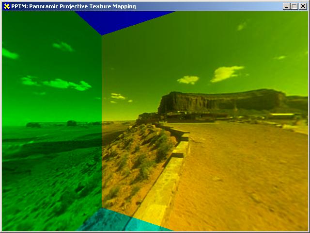
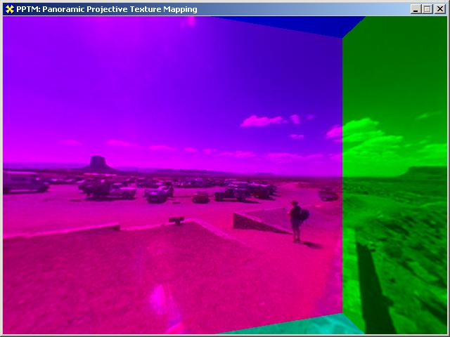
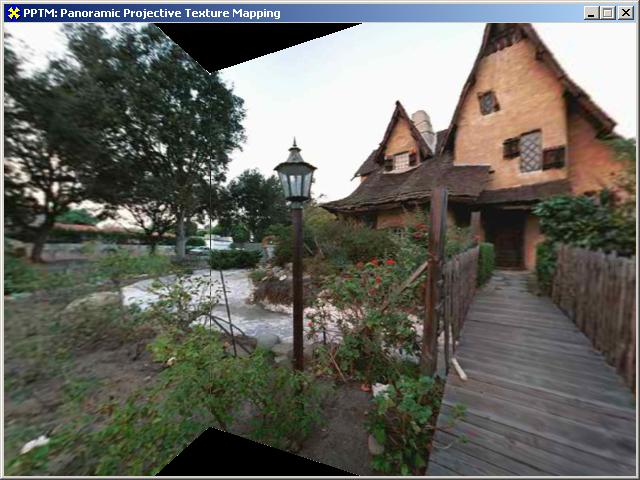
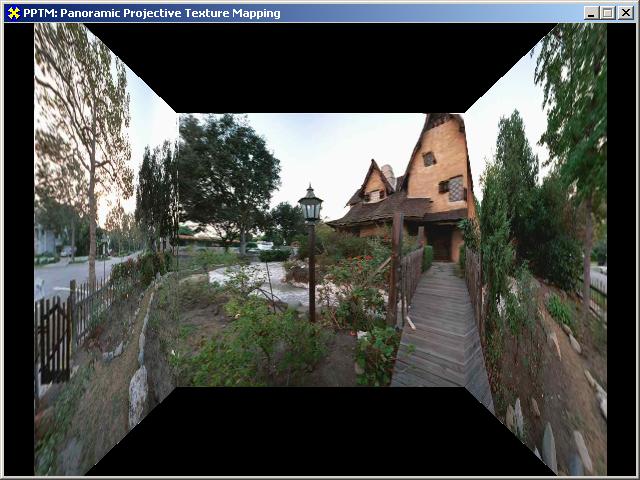
2 Figure 1: Panoramic projective texture mapping Left image is the projection from cubic panorama (two faces of the projection source are not shown). Right image is the projection from cylindrical panorama. which capture what is visible along all directions from a viewer position. A cylindrical panorama is a rectangular texture map, which contains texels parameterized with cylindrical coordinates. Figure 1 shows the concepts of projective texture mapping from panorama. Our method achieves real-time performance, because it is implemented fully by 3D graphics hardware with DirectX 8 API. From now on, we will refer to our method as panoramic projective texture mapping (PPTM) to distinguish it from standard projective texture mapping. 2. Related Work 2.1. Texture mapping and Environment mapping Texture mapping is a technique of introducing visual details into a scene 7. There are many variations in texture mapping, mainly according to the dimensionality and usage. 1D, 2D, or 3D textures can be used according to the dimensions of the data domain. Texture maps can represent surface colors, transparency, bumps, or normal vectors according to the contents of the map. Texture maps may contain the environment to be used for environment mapping 6. In environment mapping, what is visible from a point is captured and contained in a texture map. It is accessed with the direction of reflected view vector, so that surfaces can reflect the environment. Ray-tracing-like reflection can be performed easily without complex computation. Recent 3D graphics hardware has built-in environment mapping module, so that it can be performed in real-time Projective texture mapping and its hardware implementation Texture mapping is performed by the assignment of texture coordinates to all the points on the scene geometry. Usually, texture coordinates are assigned as parametric coordinates of surfaces or assigned manually. But projective texture mapping provides another method of texture coordinate assignment. With this method, a texture is projected onto object surfaces, like slide projection 15. Most of the current graphics hardwares can handle projective texturing 1,11. First, all the points on the scene geometry are given 3D texture coordinates which are their camera space locations. These coordinates are then transformed to the projection coordinate system, where the origin is at the center of projection. The coordinates are divided by z-component in order to perform perspective projection. This procedure is similar to the viewing and projection transformations in normal image rendering, and can be represented as a single 4 4 matrix. This matrix is set as a texture transformation matrix maintained by the graphics hardware. When polygons are drawn with this configuration, the automatic transformation of texture coordinates gives the final 2D coordinates to access the texture map. Projective texture mapping is useful in many imagebased applications. If the images are taken from photographs of real scenes, they can be thought of as transformed perspectively in the capturing process. Therefore, virtual environment can be modeled easily using the images as projecting sources. Moreover, it eliminates the need for complex or laborious process of texture coordinate assignment.
3 However, the conventional projective texture mapping technique is limited to one rectangular image. Therefore, projective texturing cannot be performed with panoramic images. Moreover, with the limited field of view, the coverage of the projection is limited only to a part of the scene, which may be a problem in many VR applications Panoramic rendering from fixed viewpoint QuicktimeVR 3 introduced a simple, but realistic virtual reality system. It uses cylindrical images and provides look-around views from a fixed viewpoint. Even though viewpoints cannot be relocated smoothly, QuicktimeVR has been used widely because it can generate realistic virtual environments easily from photographs. There are many commercial software packages for authoring and rendering cylindrical panorama 16. Most of them employ software-based renderers, since rendering cylindrical maps involves nonlinear warping and is difficult to handle with graphics hardware. Cylindrical panorama can be rendered in hardware by modeling polygonal approximation and texture prewarping. In other words, arbitrary polygonal models can be used in the panorama authoring stage, so that the model contains texture maps, which are pre-warped appropriately Image-based modeling using a single image In image-based modeling, 3D scene modeling is performed based on input images. The types and sizes of modeling entities are extracted from images, usually with the user s intervention, and input images are used as texture maps with the extracted geometry 4,8,9,10,12. The objective of these approaches is modeling a 3D scene so that it can represent the contents in source images as well as possible. Some of the approaches use multiple images 4 or a video sequence. On the other hand, a single image can also be used for image-based modeling. Tour-into-the-picture (TIP) 8 is one of the approaches. With this scheme, a simple rectangular structure is constructed by the user s specification of the vanishing point. The source image is then used as a texture map of the rectangles for future navigation. For rendering, it uses its own logic implemented in software, to determine texture coordinates for the points on the geometry. TIP was extended by Kang et al. 9, so that broader range of images can be handled by using vanishing lines. Spherical and cylindrical panorama can also be used as source images. It is implemented by modeling the background as a large spherical or cylindrical mesh with the source panorama as textures. OpenGL performs realtime rendering. In order to use panoramic images without warping, the background mesh should be tessellated into many polygons. Since the panorama is not projected to the scene, panoramic-to-planar pre-warping is needed for foreground objects in order to extract textures for them. All of these works use software rendering or nonprojective texture mapping, which assigns static texture coordinates to the polygonal mesh. Software rendering is slow. Moreover, non-projective texture mapping requires warping of the source image in order to nullify the effect of projection during the capture of the source image. Using projective texture mapping would simplify the modeling and rendering processes. 3. Panoramic projective texture mapping (PPTM) Conventional projective texture mapping uses simple planar image as its source of projection. However, its field of view is limited, and the degree of freedom in virtual environment modeling is also limited. Panoramic images, on the other hand, provide wider fields of view for the projection. Therefore, the whole environment can receive the projection from one image. We use two types of panorama as projection sources, cubic and cylindrical. The details of these parameterizations are explained in the next two sections. With these schemes, virtual environments can be represented by rendering polygonal models with PPTM enabled. An efficient implementation will also be presented, which takes advantage of hardware acceleration. 4. Projective texturing from cubic panorama (Cubic PPTM) Cubic panorama captures 360 field of view horizontally and vertically, and stores the result in six faces of a cube. With conventional projective texture mapping, cubic panorama can be projected onto scene geometry with six concurrent projective texturing, each with perspective projection of 90 field of view. But projection of cubic panorama is not simple when two or more textures out of the six are projected onto a polygon simultaneously, because hardware texturing requires that a texture be assigned to a whole polygon. The images in Figure 1 show these cases. In these cases, the polygon should be subdivided along the projection of frustum boundaries, so that each can have its own texture. But this may make the scene more complex. Moreover, dynamically changing
4 texture mapping cannot be handled, such as moving objects in static projection or moving projection source. Therefore, we propose a method to project from a cubic texture directly to overcome these limitations. Recent graphics hardware provides cubic environment mapping as a method of environment mapping. Texels in cubic panorama are indexed with the directional 3-vector from the center of the cube. So, reflection on a point is modeled as a texel indexed by the reflected view vector at the point. Instead of using it for reflection, we can use the cubic environment mapping method for projective texture mapping with cubic panorama. A 3D point receiving the projection is transformed into the coordinates in projection space, where the origin is at the center of the cubic projection and the axes are aligned with the cube. Then, the transformed coordinates can be used to index the cubic panorama with cubic environment mapping hardware. In this way, any polygon can receive projection from cubic panorama. Generated Automatically for Each Pixel Eye Coordinate Vector Te w World Coordinate Vector Tw p Projection Coordinate Vector Used for Cubic Environment Mapping Figure 2: Determination of Texture Coordinates for Cubic PPTM Texture coordinates for cubic PPTM are determined as shown in Figure 2. Graphics hardware can generate 3D texture coordinates with camera space positions automatically. Let the eye coordinate vector be ( x, y, z) and Te be the transformation from eye coordinates to w world coordinates. Te is the inverse of the viewing w transformation, which can be retrieved using DirectX API. Tw is the transformation from world coordinates to p projection coordinates. The projection coordinate system has the origin at the center of the cube and the axes are aligned with the cube. Tw is determined by placing and p orienting the projection source. Then, T = T w pte w gives the whole transformation from eye coordinates to projection coordinates. If T is set as the texture transformation matrix, graphics hardware transforms the texture coordinates generated automatically with this transformation. With these configurations, texture mapping with cubic projection is performed by setting the texture operation mode to cubic environment mapping. All of these operations are performed on a per-pixel basis by the graphics hardware. Conventional projective texture mapping is implemented in a similar way. The only difference is that it performs division-by-z in projection coordinates to get 2D texture coordinates, while our cubic projection uses the 3D vector in projection space in order to determine the texture coordinates for cubic environment mapping. The pseudo code for rendering is shown in Figure 3. DirectX API does all configuration and rendering. There is much flexibility in the assignment of textures, i.e., two or more projections can be performed simultaneously and some polygons may not receive any projection. T : Texture Transform Matrix : Inverse of Viewing Transform Te w Tw p : Transformation from World Coordinates to Projection Coordinates for each frame Configure Automatic Texture Coordinate Generation Mode as Camera_Space_Position Configure Cubic Environment Mapping mode Compute Te w for each Cubic Projective Texture Set texture T = T w T p e w Set Texture Transformation Matrix as T Draw Polygons receiving Current Projection endfor Configure Rendering mode to normal rendering Draw Polygons Not receiving Projective Texture endfor Figure 3: Pseudo code of Cubic PPTM
5 5. Projective texturing from cylindrical panorama (Cylindrical PPTM) Cylindrical textures are being used in many applications, since they provide a 360-degree horizontal field of view and constant horizontal sampling density. However, using cylindrical maps directly with hardware acceleration is difficult, because cylindrical mapping involves nonlinear computations, which cannot be handled easily by graphics hardware. So, in many look-around applications with cylindrical maps, such as QuickTimeVR, texture coordinates are determined by the software renderer. Since using cubic panorama is usually faster than using cylindrical panorama, a cylindrical map may be resampled into a cubic map. But cylindrical maps are easy to obtain and provide constant horizontal sampling rates. Moreover, resampling may degrade the quality of the maps. Projection with cylindrical panorama is a process of warping a cylindrical texture map onto a plane. We propose an algorithm for this process using graphics hardware Main idea First, we define projection plane, onto which a cylindrical map is warped locally. Then, conventional planar projective texture mapping is used with the warped texture map on the projection plane. In order to utilize graphics hardware and enhance rendering performance, we perform the nonlinear local warping on-the-fly using bump mapping hardware. From now on, we use ( θ, v) for the cylindrical texture coordinates in [0..1] for cylindrical panorama, and ( u, v ) for the planar texture coordinates on the projection plane. 3-vector ( x, y, z) is a location in projection coordinate system, where the origin is at the center of the cylinder. The z-axis is aligned with the axis of the cylinder, and the x-axis is aligned with θ = 0. Transformation from eye coordinates to projection coordinates is performed in the same way as cubic PPTM. Let H be the height of the unit cylinder given as H = 2 tan(0.5 FOV), where FOV is the vertical field of view of the cylindrical panorama. Then, ( θ, v) is related to ( x, y, z) as follows. Here, atan2() is arctangent function in standard C library, which gives angle in [-π..π] for output. atan2( y, x) θ = π 1 z v = H 2 2 x + y (1) θ 0 DOP For local warping, we define the direction of projection (DOP), which becomes the normal vector of the projection plane. In other words, DOP is the direction that we are most interested in for the projection. We use DOP perpendicular to the cylinder, so it is defined simply by θ, which is the angle of DOP from the x-axis. Then, the 0 projection plane is placed at unit distance from the origin with the normal vector along DOP. Figure 4 shows a 2- dimensional view of this configuration. Suppose that ( x, y ) is a projection of ( x, y, z) onto the local coordinates of the projection plane. Then, the above equations become the following equations which determine ( θ, v). And it determines ( θ, v) for given ( x, y ). atan( x ) θ = θ0 + 2π 1 y v = H x The main idea of our work is to decompose these equations into a linear approximation and nonlinear residuals, and fill the bump map with the nonlinear part. The bump map is used to perturb texture coordinates determined by the linear part. This is done by decomposing Equation 2 as follows. θ = θ0 + ax + Rθ ( x ) v = by + R ( x, y ) v The residual parts are given as follows. atan( x ) Rθ ( x ) = ax 2π 1 y Rv ( x, y ) = by H x x Projection Plane Figure 4: Projection Plane and Direction of Projection (DOP) (2) (3) (4)
6 Here, a and b are the coefficients of the linear approximations of ( θ, v) according to ( x, y ). They are computed before rendering so that the magnitudes of the residual parts are minimized. Because texture coordinates are interpolated linearly by texture mapping hardware, we encode the linear components as regular texture coordinates of the polygon. The residual components are encoded as bump maps to perturb the linear texture coordinates. Implementation details are explained in the next subsection Using environment mapped bump mapping (EMBM) for hardware support Recent improvement in texture mapping hardware introduced multi-texture mapping. With multi-texture mapping, two or more textures can be applied to a polygon in a single rendering pass. Each texture is applied at each stage. The result of the previous stage and the texture for the current stage are combined by various operations, such as add, subtract, multiply, etc. One of the operational modes of multi-texturing is environment mapped bump mapping (EMBM) where texture coordinates in the second stage are perturbed by the texel values sampled in the first stage. This functionality is designed originally for bumped reflection, where the environment is reflected using environment mapping. In this work, however, this functionality is used to perturb texture coordinates and perform nonlinear warping with hardware support. Because residual parts shown in Equation 4 are approximated as a bump perturbation map, the resolution of the bump map may affect the quality of projective texturing bump map is used in this work, and there is no noticeable artifact due to the approximation Implementation with single-pass rendering Cylindrical PPTM can be implemented using EMBM and multi-texturing capabilities of 3D graphics hardware. With multi-texture capability, multiple textures can be applied onto object geometry in a single rendering pass. Figure 5 shows the procedure for determining texture coordinates. For the first texture stage, texture operation is set as EMBM and bump perturbation map is used as texture. The bump perturbation map contains the amounts of perturbation needed for all texels, which are computed by the residual parts of cylindrical parameterization given in Equation 4. For the second texture stage, the cylindrical First stage: generated automatically for each pixel Second stage: generated automatically for each pixel Standard Projective Texture Mapping Eye Space Vector Te w World Space Vector Tw p Projection Space Vector Eye Space Vector Te w World Space Vector Tw p Projection Space Vector 2D Vector on Projection Plane 2D vector on Projection Plane Access bump map Perturb texture parameter ( θ, v) as linear part of Equation 3 Final ( θ v) Figure 5: Determination of texture coordinates for cylindrical PPTM
 Cylindrical map We found that current 3D graphics hardware has problems in implementing this procedure, even though DirectX supports the capability. We tested nvidia GeForce3 and ATI Radeon.")

7 transformation matrix. Most of the procedure is similar to standard projective texture mapping. But the use of EMBM makes it possible to perform nonlinear warping with graphics hardware. (a) Cylindrical map We found that current 3D graphics hardware has problems in implementing this procedure, even though DirectX supports the capability. We tested nvidia GeForce3 and ATI Radeon. They do not function correctly when EMBM is used and projective texturing is turned on in multi-stages. However, DirectX reference renderer (software renderer) executes this implementation correctly. It seems that current hardware did not implement the entire functionality because this usage is beyond the scope of its original objective, which is environment mapping. We hope that full functionality is supported in the near future. Therefore, we propose another rendering method in the next subsection, which is less efficient but possible with current graphics hardware Implementation with multi-pass rendering (b) Projected to Projection Plane (c) Final Result Figure 6 Cylindrical PPTM with twopass rendering: The area in red rectangle in (a) is specified by DOP and it is projected using EMBM (first pass). Standard projective texturing with (b) results in final result in (c). Since many graphics hardware do not function correctly when EMBM and projective texturing are used simultaneously, we propose a multi-pass rendering approach here. It is similar to the single-pass approach in the previous subsection, but it renders in two passes, i.e., rendering takes place two times for a final result. In the first pass, texture operation mode and texture maps are set up in the same way as single-pass implementation. But projective texturing is not set up, and viewing direction is aligned with the direction of projection (DOP). This results in the image, which contains a part of the panorama projected onto the projection plane. In the second rendering pass, this image is used as texture and appropriate projective texturing is set up for the final image. Figure 6 shows the images generated in this process. Because we warp the cylindrical map explicitly, rendering performance with this method is lower than the single-pass method. Moreover, it is required to perform the first pass rendering more than once, since local warping cannot cover all views from the projection source. Polygons can be grouped according to their locations, so that each group can be projected with each first-pass rendering result. This problem does not occur with the single-pass method. panorama is used as the texture. For both stages, texture coordinates are generated by automatic texture generation capability, and transformed appropriately by the texture
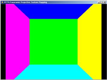
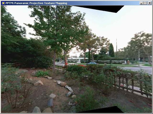
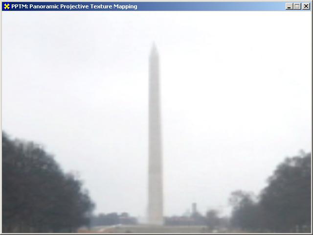
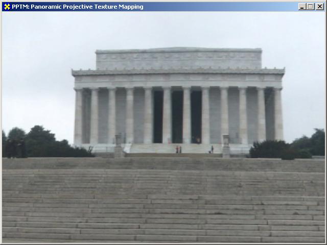
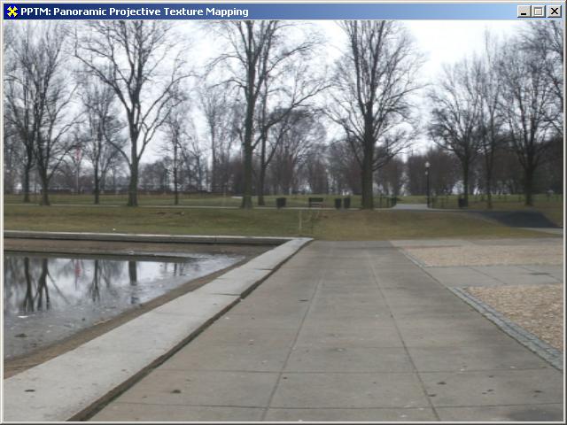
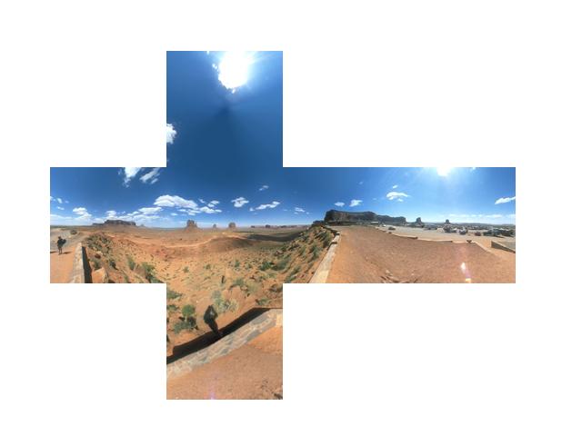
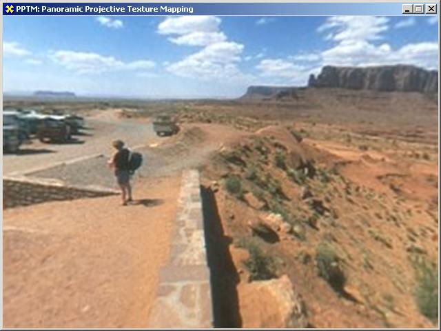
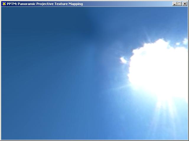
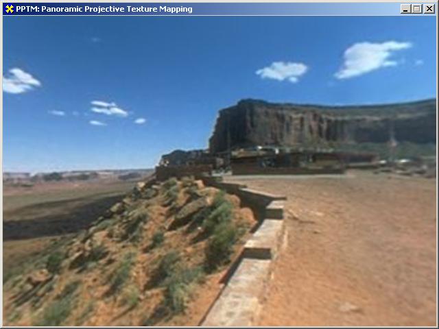
8 6. Applications and Experimental Results Cubic and cylindrical PPTM were implemented using DirectX 8 API. Similar implementation would be possible with OpenGL. In the following subsections, various applications of PPTM and their results are presented Panorama Viewer ( viewpoint and projection source at the same location ) When the source of projection is located at the viewpoint, PPTM works as panorama viewer, which is similar to QuicktimeVR. Since panorama is projected from the viewpoint and rendered from the same location, we can use any scene geometry as long as it covers the entire screen. Because it is the simplest geometry, we use a rectangle placed on the screen of the viewing frustum. In other words, the rectangle is rendered from the viewpoint, while it receives the projection from the viewpoint. This rectangle is always attached to the viewing frustum when the user rotates the viewing direction or changes the field of view. Our panorama viewer supports both cubic and cylindrical panorama, and Figures 7 and 8 show the rendered results using the panorama viewer. With the cubic panorama viewer, everything visible from a fixed viewpoint can be captured and looked around. Figure 7(a) is the cubic panorama data we used. Figure 7(b) shows rendered images when the user changes viewing direction of field of view. This functionality can be obtained by rendering six squares with static texture coordinates. However, we believe that the approach of projection gives possibility for more applications. In the cylindrical panorama viewer, the direction of projection (DOP) changes according to the viewing direction. Cylindrical panoramic viewer provides the same rendering capability as QuicktimeVR. But our viewer renders fast even with large resolution, because it takes advantage of hardware rendering. On the other hand, software renderer such as QuicktimeVR degrades image quality when the user changes viewing direction in order to achieve real-time functionality. Figure 8(a) is a sample panorama and Figure 8(b) shows various rendered images Projection of Panorama onto Geometry In Figures 9 and 10, panoramas are projected onto polygonal geometry. In our examples, panoramas rotate while they are projecting the textures, which is not possible with static texture mapping. In the results of Figure 9, the cubic panorama in Figure 7(a) was used, and simple cubic geometry in Figure 9(a) is used. In the rendered images in Figure 9(b), the colors of the polygons are modulated by the projected texture colors. It is shown that two or three faces of the texture contribute together to one polygon, which is not possible with conventional projective texture mapping. This example is a kind of light mapping, and the modeling of full 360º light is possible to be used for light mapping. Figure 10 is a similar experiment with cylindrical panorama. In this case, the polygons selects incoming texture colors as their final colors Rendering speed We used a Pentium III 450 MHz PC with GeForce3 graphics card. For cubic PPTM, rendering speed is very high. When cylindrical panorama is used, the frame rate is much lower than the case of cubic panorama. This is due to the overhead of multi-pass rendering. In the example of cylindrical projection, we performed three renderings for the first pass, because single explicit warping cannot cover all the polygonal models. However, it still shows high frame rates even for large resolutions, when compared with software renderers. If future graphics hardware works well with single-pass implementation of cylindrical PPTM, the frame rate will increase a lot. The next table shows the measured rendering frame rates in frames per second. Resolution 640 x x 768 CUBIC VIEWER CYL VIEWER CUBIC PROJECTION CYL PROJECTION Conclusion and future work We presented the concept of panoramic projective texture mapping (PPTM), and proposed algorithms to use cubic and cylindrical panorama as projecting sources. With this scheme, a single panoramic texture can be projected to the whole scene without additional modeling or subdivision of polygonal models. Examples of the projection were shown for panoramic viewer as well as more general cases. We believe that projective texture mapping from panorama can be used in many useful applications. As future work, our method could be applied to many image-based rendering techniques. First, it could be used with an image-based modeler so that a panorama can work
9 as an input image for modeling. Virtual environments with more degrees of navigation could be generated. Since photographs can be modeled as projecting texture into the scene, many image-based rendering techniques use projective texture mapping. Our method could be combined with some of existing image-based rendering techniques using projective textures 2,4. Another future work could be the projection of more complex texture maps, which are modeled nonlinearly. For example, concentric mosaics 13 is similar to cylindrical map, but it is parameterized differently to capture horizontal parallax with 3D data. It is not possible to render it using 3D graphics hardware due to its nonlinearity. Since our work proposes the baseline of projecting nonlinear texture map using graphics hardware, it could be extended to using concentric mosaics as rendering entity. Acknowledgement The authors wish to thank Ge Jin for the help in the preparation of demo videos. This work was partially supported by George Washington University Presidential Fellowship. References 1. D. Blythe, et al., Advanced Graphics Programming Techniques Using OpenGL, Siggraph 2000 Course Notes. 2. C. Buehler, M. Bosse, L. McMillan, S. Gortler, and M. Cohen, Unstructured Lumigraph Rendering, Proceedings of SIGGRAPH 2001, , S.E. Chen, Quicktime VR An Image-Based Approach to Virtual Environment Navigation, Proceedings of SIGGRAPH 95, 29-38, P.E. Debevec, C.J. Taylor, and J. Malik, Modeling and Rendering Architecture from Photographs: A Hybrid Geometry- and Image-Based Approach, Proceedings of SIGGRAPH 96, 11-20, P.E. Debevec, Y. Yu, and G.D. Borshukov, Efficient View-Dependent Image-Based Rendering with Projective Texture-Mapping, Eurographics Rendering Workshop 1998, , N. Greene, Environment Mapping and Other Applications of World Projections, IEEE Computer Graphics & Applications, 6(11):21-29, P.S. Heckbert, Survey of Texture Mapping, IEEE Computer Graphics & Applications, 6(11):56-67, Y. Horry, K. Anjyo, and K. Arai, Tour Into the Picture: Using Spidery Mesh Interface to Make Animation from a Single Image, Proceedings of SIGGRAPH 97, , H.W. Kang, S.H. Pyo, K. Anjyo, and S.Y. Shin, Tour Into the Picture Using a Vanishing Line and its Extension to Panoramic Images, Computer Graphics Forum, 20(3): , D. Liebowitz, A. Criminisi, and A. Zisserman, Creating Architectural Models from Images, Computer Graphics Forum, 18(3):39-50, Microsoft, DirectX 8 Programmer s Manual. 12. B.M. Oh, M. Chen, J. Dorsey, and F. Durand, Image- Based Modeling and Photo Editing, Proceedings of SIGGRAPH 2001, , H.Y. Shum and L.W. He, Rendering with Concentric Mosaics, Proceedings of SIGGRAPH 99, , R. Szeliski and H.Y. Shum, Creating Full Panoramic Mosaics and Environment Maps, Proceedings of SIGGRAPH 97, , F.M. Weinhaus and R.N. Devich, Photogrammetric Texture Mapping onto Planar Polygons, Graphical Models and Image Processing, 61(2):63-83,

10 Kim and Hahn / Projective Texture Mapping with Full Panorama (a) (b) (a) (b) Figure 8: Result of Cylindrical Panorama Viewer (a) (b) Figure 9: Result of Cubic Panorama Projection (a) (b) Figure 10: Result of Cylindrical Panorama Projection
Tour Into the Picture using a Vanishing Line and its Extension to Panoramic Images
 EUROGRAPHICS 2001 / A. Chalmers and T.-M. Rhyne (Guest Editors) Volume 20 (2001), Number 3 Tour Into the Picture using a Vanishing Line and its Extension to Panoramic Images Hyung Woo Kang, Soon Hyoung
Image-Based Rendering. Johns Hopkins Department of Computer Science Course : Rendering Techniques, Professor: Jonathan Cohen
 Image-Based Rendering Image-Based Rendering What is it? Still a difficult question to answer Uses images (photometric( info) as key component of model representation What s Good about IBR Model acquisition
A Review of Image- based Rendering Techniques Nisha 1, Vijaya Goel 2 1 Department of computer science, University of Delhi, Delhi, India
 A Review of Image- based Rendering Techniques Nisha 1, Vijaya Goel 2 1 Department of computer science, University of Delhi, Delhi, India Keshav Mahavidyalaya, University of Delhi, Delhi, India Abstract
Image Base Rendering: An Introduction
 Image Base Rendering: An Introduction Cliff Lindsay CS563 Spring 03, WPI 1. Introduction Up to this point, we have focused on showing 3D objects in the form of polygons. This is not the only approach to
Morphable 3D-Mosaics: a Hybrid Framework for Photorealistic Walkthroughs of Large Natural Environments
 Morphable 3D-Mosaics: a Hybrid Framework for Photorealistic Walkthroughs of Large Natural Environments Nikos Komodakis and Georgios Tziritas Computer Science Department, University of Crete E-mails: {komod,
CS6670: Computer Vision
 CS6670: Computer Vision Noah Snavely Lecture 7: Image Alignment and Panoramas What s inside your fridge? http://www.cs.washington.edu/education/courses/cse590ss/01wi/ Projection matrix intrinsics projection
CS 130 Final. Fall 2015
 CS 130 Final Fall 2015 Name Student ID Signature You may not ask any questions during the test. If you believe that there is something wrong with a question, write down what you think the question is trying
Hardware-Assisted Relief Texture Mapping
 EUROGRAPHICS 0x / N.N. and N.N. Short Presentations Hardware-Assisted Relief Texture Mapping Masahiro Fujita and Takashi Kanai Keio University Shonan-Fujisawa Campus, Fujisawa, Kanagawa, Japan Abstract
CS 354R: Computer Game Technology
 CS 354R: Computer Game Technology Texture and Environment Maps Fall 2018 Texture Mapping Problem: colors, normals, etc. are only specified at vertices How do we add detail between vertices without incurring
Scene Modeling for a Single View
 Scene Modeling for a Single View René MAGRITTE Portrait d'edward James with a lot of slides stolen from Steve Seitz and David Brogan, Breaking out of 2D now we are ready to break out of 2D And enter the
CSE528 Computer Graphics: Theory, Algorithms, and Applications
 CSE528 Computer Graphics: Theory, Algorithms, and Applications Hong Qin State University of New York at Stony Brook (Stony Brook University) Stony Brook, New York 11794--4400 Tel: (631)632-8450; Fax: (631)632-8334
Image-Based Deformation of Objects in Real Scenes
 Image-Based Deformation of Objects in Real Scenes Han-Vit Chung and In-Kwon Lee Dept. of Computer Science, Yonsei University sharpguy@cs.yonsei.ac.kr, iklee@yonsei.ac.kr Abstract. We present a new method
Computer Science 426 Midterm 3/11/04, 1:30PM-2:50PM
 NAME: Login name: Computer Science 46 Midterm 3//4, :3PM-:5PM This test is 5 questions, of equal weight. Do all of your work on these pages (use the back for scratch space), giving the answer in the space
Lecture 3 Sections 2.2, 4.4. Mon, Aug 31, 2009
 Model s Lecture 3 Sections 2.2, 4.4 World s Eye s Clip s s s Window s Hampden-Sydney College Mon, Aug 31, 2009 Outline Model s World s Eye s Clip s s s Window s 1 2 3 Model s World s Eye s Clip s s s Window
Capturing and View-Dependent Rendering of Billboard Models
 Capturing and View-Dependent Rendering of Billboard Models Oliver Le, Anusheel Bhushan, Pablo Diaz-Gutierrez and M. Gopi Computer Graphics Lab University of California, Irvine Abstract. In this paper,
Real Time Rendering. CS 563 Advanced Topics in Computer Graphics. Songxiang Gu Jan, 31, 2005
 Real Time Rendering CS 563 Advanced Topics in Computer Graphics Songxiang Gu Jan, 31, 2005 Introduction Polygon based rendering Phong modeling Texture mapping Opengl, Directx Point based rendering VTK
Image-Based Rendering. Johns Hopkins Department of Computer Science Course : Rendering Techniques, Professor: Jonathan Cohen
 Image-Based Rendering Image-Based Rendering What is it? Still a difficult question to answer Uses images (photometric( info) as key component of model representation What s Good about IBR Model acquisition
Practical Shadow Mapping
 Practical Shadow Mapping Stefan Brabec Thomas Annen Hans-Peter Seidel Max-Planck-Institut für Informatik Saarbrücken, Germany Abstract In this paper we propose several methods that can greatly improve
Efficient Visibility Processing for Projective Texture-mapping
 To appear in Journal of Computers and Graphics Efficient Visibility Processing for Projective Texture-mapping Yizhou Yu Computer Science Division, University of California at Berkeley, USA Abstract Projective
Game Architecture. 2/19/16: Rasterization
 Game Architecture 2/19/16: Rasterization Viewing To render a scene, need to know Where am I and What am I looking at The view transform is the matrix that does this Maps a standard view space into world
Announcements. Mosaics. How to do it? Image Mosaics
 Announcements Mosaics Project artifact voting Project 2 out today (help session at end of class) http://www.destination36.com/start.htm http://www.vrseattle.com/html/vrview.php?cat_id=&vrs_id=vrs38 Today
Computer Graphics. Lecture 9 Environment mapping, Mirroring
 Computer Graphics Lecture 9 Environment mapping, Mirroring Today Environment Mapping Introduction Cubic mapping Sphere mapping refractive mapping Mirroring Introduction reflection first stencil buffer
Image-Based Modeling and Rendering
 Traditional Computer Graphics Image-Based Modeling and Rendering Thomas Funkhouser Princeton University COS 426 Guest Lecture Spring 2003 How would you model and render this scene? (Jensen) How about this
An Algorithm for Seamless Image Stitching and Its Application
 An Algorithm for Seamless Image Stitching and Its Application Jing Xing, Zhenjiang Miao, and Jing Chen Institute of Information Science, Beijing JiaoTong University, Beijing 100044, P.R. China Abstract.
Computer Graphics. - Texturing Methods -
 Computer Graphics - Texturing Methods - Overview Last time BRDFs Shading Today Texturing Texture parameterization Procedural methods Procedural textures Fractal landscapes Next lecture Texture filtering
CPSC / Texture Mapping
 CPSC 599.64 / 601.64 Introduction and Motivation so far: detail through polygons & materials example: brick wall problem: many polygons & materials needed for detailed structures inefficient for memory
Mosaics. Today s Readings
 Mosaics VR Seattle: http://www.vrseattle.com/ Full screen panoramas (cubic): http://www.panoramas.dk/ Mars: http://www.panoramas.dk/fullscreen3/f2_mars97.html Today s Readings Szeliski and Shum paper (sections
Image-Based Rendering. Image-Based Rendering
 Image-Based Rendering Image-Based Rendering What is it? Still a difficult question to answer Uses images (photometric info) as key component of model representation 1 What s Good about IBR Model acquisition
Complex Features on a Surface. CITS4241 Visualisation Lectures 22 & 23. Texture mapping techniques. Texture mapping techniques
 Complex Features on a Surface CITS4241 Visualisation Lectures 22 & 23 Texture Mapping Rendering all surfaces as blocks of colour Not very realistic result! Even with shading Many objects have detailed
SUMMARY. CS380: Introduction to Computer Graphics Projection Chapter 10. Min H. Kim KAIST School of Computing 18/04/12. Smooth Interpolation
 CS38: Introduction to Computer Graphics Projection Chapter Min H. Kim KAIST School of Computing Smooth Interpolation SUMMARY 2 Cubic Bezier Spline To evaluate the function c(t) at any value of t, we perform
Efficient Rendering of Glossy Reflection Using Graphics Hardware
 Efficient Rendering of Glossy Reflection Using Graphics Hardware Yoshinori Dobashi Yuki Yamada Tsuyoshi Yamamoto Hokkaido University Kita-ku Kita 14, Nishi 9, Sapporo 060-0814, Japan Phone: +81.11.706.6530,
Image Warping and Mosacing
 Image Warping and Mosacing 15-463: Rendering and Image Processing Alexei Efros with a lot of slides stolen from Steve Seitz and Rick Szeliski Today Mosacs Image Warping Homographies Programming Assignment
Image-Based Modeling and Rendering. Image-Based Modeling and Rendering. Final projects IBMR. What we have learnt so far. What IBMR is about
 Image-Based Modeling and Rendering Image-Based Modeling and Rendering MIT EECS 6.837 Frédo Durand and Seth Teller 1 Some slides courtesy of Leonard McMillan, Wojciech Matusik, Byong Mok Oh, Max Chen 2
But, vision technology falls short. and so does graphics. Image Based Rendering. Ray. Constant radiance. time is fixed. 3D position 2D direction
 Computer Graphics -based rendering Output Michael F. Cohen Microsoft Research Synthetic Camera Model Computer Vision Combined Output Output Model Real Scene Synthetic Camera Model Real Cameras Real Scene
Scene Modeling for a Single View
 Scene Modeling for a Single View René MAGRITTE Portrait d'edward James CS194: Image Manipulation & Computational Photography with a lot of slides stolen from Alexei Efros, UC Berkeley, Fall 2014 Steve
Image-Based Modeling and Rendering
 Image-Based Modeling and Rendering Richard Szeliski Microsoft Research IPAM Graduate Summer School: Computer Vision July 26, 2013 How far have we come? Light Fields / Lumigraph - 1996 Richard Szeliski
A million pixels, a million polygons. Which is heavier? François X. Sillion. imagis* Grenoble, France
 A million pixels, a million polygons. Which is heavier? François X. Sillion imagis* Grenoble, France *A joint research project of CNRS, INRIA, INPG and UJF MAGIS Why this question? Evolution of processing
Scene Modeling for a Single View
 Scene Modeling for a Single View René MAGRITTE Portrait d'edward James with a lot of slides stolen from Steve Seitz and David Brogan, 15-463: Computational Photography Alexei Efros, CMU, Fall 2005 Classes
A Three Dimensional Image Cache for Virtual Reality
 A Three Dimensional Image Cache for Virtual Reality Gernot Schaufler and Wolfgang Stürzlinger GUP, Johannes Kepler Universität Linz, Altenbergerstr.69, A- Linz, Austria/Europe schaufler@gup.uni-linz.ac.at
Scene Modeling for a Single View
 on to 3D Scene Modeling for a Single View We want real 3D scene walk-throughs: rotation translation Can we do it from a single photograph? Reading: A. Criminisi, I. Reid and A. Zisserman, Single View Metrology
Real-time Generation and Presentation of View-dependent Binocular Stereo Images Using a Sequence of Omnidirectional Images
 Real-time Generation and Presentation of View-dependent Binocular Stereo Images Using a Sequence of Omnidirectional Images Abstract This paper presents a new method to generate and present arbitrarily
CS451Real-time Rendering Pipeline
 1 CS451Real-time Rendering Pipeline JYH-MING LIEN DEPARTMENT OF COMPUTER SCIENCE GEORGE MASON UNIVERSITY Based on Tomas Akenine-Möller s lecture note You say that you render a 3D 2 scene, but what does
3D Polygon Rendering. Many applications use rendering of 3D polygons with direct illumination
 Rendering Pipeline 3D Polygon Rendering Many applications use rendering of 3D polygons with direct illumination 3D Polygon Rendering What steps are necessary to utilize spatial coherence while drawing
3D Programming. 3D Programming Concepts. Outline. 3D Concepts. 3D Concepts -- Coordinate Systems. 3D Concepts Displaying 3D Models
 3D Programming Concepts Outline 3D Concepts Displaying 3D Models 3D Programming CS 4390 3D Computer 1 2 3D Concepts 3D Model is a 3D simulation of an object. Coordinate Systems 3D Models 3D Shapes 3D Concepts
Viewing with Computers (OpenGL)
") We can now return to three-dimension?', graphics from a computer perspective. Because viewing in computer graphics is based on the synthetic-camera model, we should be able to construct any of the classical
We can now return to three-dimension?', graphics from a computer perspective. Because viewing in computer graphics is based on the synthetic-camera model, we should be able to construct any of the classical
Reading. 18. Projections and Z-buffers. Required: Watt, Section , 6.3, 6.6 (esp. intro and subsections 1, 4, and 8 10), Further reading:
, Further reading:") Reading Required: Watt, Section 5.2.2 5.2.4, 6.3, 6.6 (esp. intro and subsections 1, 4, and 8 10), Further reading: 18. Projections and Z-buffers Foley, et al, Chapter 5.6 and Chapter 6 David F. Rogers
Reading Required: Watt, Section 5.2.2 5.2.4, 6.3, 6.6 (esp. intro and subsections 1, 4, and 8 10), Further reading: 18. Projections and Z-buffers Foley, et al, Chapter 5.6 and Chapter 6 David F. Rogers
For each question, indicate whether the statement is true or false by circling T or F, respectively.
 True/False For each question, indicate whether the statement is true or false by circling T or F, respectively. 1. (T/F) Rasterization occurs before vertex transformation in the graphics pipeline. 2. (T/F)
Textures. Texture coordinates. Introduce one more component to geometry
 Texturing & Blending Prof. Aaron Lanterman (Based on slides by Prof. Hsien-Hsin Sean Lee) School of Electrical and Computer Engineering Georgia Institute of Technology Textures Rendering tiny triangles
Computer Graphics. Lecture 14 Bump-mapping, Global Illumination (1)
") Computer Graphics Lecture 14 Bump-mapping, Global Illumination (1) Today - Bump mapping - Displacement mapping - Global Illumination Radiosity Bump Mapping - A method to increase the realism of 3D objects
Computer Graphics Lecture 14 Bump-mapping, Global Illumination (1) Today - Bump mapping - Displacement mapping - Global Illumination Radiosity Bump Mapping - A method to increase the realism of 3D objects
form are graphed in Cartesian coordinates, and are graphed in Cartesian coordinates.
 Plot 3D Introduction Plot 3D graphs objects in three dimensions. It has five basic modes: 1. Cartesian mode, where surfaces defined by equations of the form are graphed in Cartesian coordinates, 2. cylindrical
Acquisition and Visualization of Colored 3D Objects
 Acquisition and Visualization of Colored 3D Objects Kari Pulli Stanford University Stanford, CA, U.S.A kapu@cs.stanford.edu Habib Abi-Rached, Tom Duchamp, Linda G. Shapiro and Werner Stuetzle University
Image stitching. Digital Visual Effects Yung-Yu Chuang. with slides by Richard Szeliski, Steve Seitz, Matthew Brown and Vaclav Hlavac
 Image stitching Digital Visual Effects Yung-Yu Chuang with slides by Richard Szeliski, Steve Seitz, Matthew Brown and Vaclav Hlavac Image stitching Stitching = alignment + blending geometrical registration
Hybrid Rendering for Collaborative, Immersive Virtual Environments
 Hybrid Rendering for Collaborative, Immersive Virtual Environments Stephan Würmlin wuermlin@inf.ethz.ch Outline! Rendering techniques GBR, IBR and HR! From images to models! Novel view generation! Putting
A simple method for interactive 3D reconstruction and camera calibration from a single view
 A simple method for interactive 3D reconstruction and camera calibration from a single view Akash M Kushal Vikas Bansal Subhashis Banerjee Department of Computer Science and Engineering Indian Institute
Image Based Rendering. D.A. Forsyth, with slides from John Hart
 Image Based Rendering D.A. Forsyth, with slides from John Hart Topics Mosaics translating cameras reveal extra information, break occlusion Optical flow for very small movements of the camera Explicit
Compositing a bird's eye view mosaic
 Compositing a bird's eye view mosaic Robert Laganiere School of Information Technology and Engineering University of Ottawa Ottawa, Ont KN 6N Abstract This paper describes a method that allows the composition
Image-based modeling (IBM) and image-based rendering (IBR)
 and image-based rendering (IBR)") Image-based modeling (IBM) and image-based rendering (IBR) CS 248 - Introduction to Computer Graphics Autumn quarter, 2005 Slides for December 8 lecture The graphics pipeline modeling animation rendering
Image-based modeling (IBM) and image-based rendering (IBR) CS 248 - Introduction to Computer Graphics Autumn quarter, 2005 Slides for December 8 lecture The graphics pipeline modeling animation rendering
Antialiasing of Environment Maps
 Volume 20, (2001 number 1pp. 5-11 COMPUTER GRAPHICS forum Antialiasing of Environment Maps Andreas Schilling 1 1 University of Tübingen, WSI/GRIS, Tübingen, Germany Email: {schilling@uni-tuebingen.de}
Efficiently Modeling 3D Scenes from a Single Image
 Efficiently Modeling 3D Scenes from a Single Image Satoshi Iizuka 1 Yoshihiro Kanamori 1 Jun Mitani 1,2 Yukio Fukui 1 1 University of Tsukuba 2 JST ERATO e-mail: iizuka@npal.cs.tsukuba.ac.jp {kanamori,
Orthogonal Projection Matrices. Angel and Shreiner: Interactive Computer Graphics 7E Addison-Wesley 2015
 Orthogonal Projection Matrices 1 Objectives Derive the projection matrices used for standard orthogonal projections Introduce oblique projections Introduce projection normalization 2 Normalization Rather
Single-view 3D Reconstruction
 Single-view 3D Reconstruction 10/12/17 Computational Photography Derek Hoiem, University of Illinois Some slides from Alyosha Efros, Steve Seitz Notes about Project 4 (Image-based Lighting) You can work
Graphics for VEs. Ruth Aylett
 Graphics for VEs Ruth Aylett Overview VE Software Graphics for VEs The graphics pipeline Projections Lighting Shading VR software Two main types of software used: off-line authoring or modelling packages
Applications of Explicit Early-Z Culling
 Applications of Explicit Early-Z Culling Jason L. Mitchell ATI Research Pedro V. Sander ATI Research Introduction In past years, in the SIGGRAPH Real-Time Shading course, we have covered the details of
Inexpensive Construction of a 3D Face Model from Stereo Images
 Inexpensive Construction of a 3D Face Model from Stereo Images M. Shahriar Hossain, Monika Akbar and J. Denbigh Starkey Department of Computer Science, Montana State University, Bozeman, MT 59717, USA.
2D rendering takes a photo of the 2D scene with a virtual camera that selects an axis aligned rectangle from the scene. The photograph is placed into
 2D rendering takes a photo of the 2D scene with a virtual camera that selects an axis aligned rectangle from the scene. The photograph is placed into the viewport of the current application window. A pixel
Polyhedral Visual Hulls for Real-Time Rendering
 Polyhedral Visual Hulls for Real-Time Rendering Wojciech Matusik Chris Buehler Leonard McMillan MIT Laboratory for Computer Science Abstract. We present new algorithms for creating and rendering visual
Light-Dependent Texture Mapping
 Light-Dependent Texture Mapping Dan Gelb, Tom Malzbender, Kevin Wu Client and Media Systems Laboratory HP Laboratories Palo Alto HPL-98-131 (R.1) April 26 th, 2001* E-mail: malzbend@hpl.hp.com texture
Shadows in the graphics pipeline
 Shadows in the graphics pipeline Steve Marschner Cornell University CS 569 Spring 2008, 19 February There are a number of visual cues that help let the viewer know about the 3D relationships between objects
Image-based Modeling and Rendering: 8. Image Transformation and Panorama
 Image-based Modeling and Rendering: 8. Image Transformation and Panorama I-Chen Lin, Assistant Professor Dept. of CS, National Chiao Tung Univ, Taiwan Outline Image transformation How to represent the
Three-Dimensional Viewing Hearn & Baker Chapter 7
 Three-Dimensional Viewing Hearn & Baker Chapter 7 Overview 3D viewing involves some tasks that are not present in 2D viewing: Projection, Visibility checks, Lighting effects, etc. Overview First, set up
Computer Graphics (CS 563) Lecture 4: Advanced Computer Graphics Image Based Effects: Part 1. Prof Emmanuel Agu
 Lecture 4: Advanced Computer Graphics Image Based Effects: Part 1. Prof Emmanuel Agu") Computer Graphics (CS 563) Lecture 4: Advanced Computer Graphics Image Based Effects: Part 1 Prof Emmanuel Agu Computer Science Dept. Worcester Polytechnic Institute (WPI) Image Based Effects Three main
Computer Graphics (CS 563) Lecture 4: Advanced Computer Graphics Image Based Effects: Part 1 Prof Emmanuel Agu Computer Science Dept. Worcester Polytechnic Institute (WPI) Image Based Effects Three main
Computergrafik. Matthias Zwicker. Herbst 2010
 Computergrafik Matthias Zwicker Universität Bern Herbst 2010 Today Bump mapping Shadows Shadow mapping Shadow mapping in OpenGL Bump mapping Surface detail is often the result of small perturbations in
Texture. Texture Mapping. Texture Mapping. CS 475 / CS 675 Computer Graphics. Lecture 11 : Texture
 Texture CS 475 / CS 675 Computer Graphics Add surface detail Paste a photograph over a surface to provide detail. Texture can change surface colour or modulate surface colour. Lecture 11 : Texture http://en.wikipedia.org/wiki/uv_mapping
Chapter 5. Projections and Rendering
 Chapter 5 Projections and Rendering Topics: Perspective Projections The rendering pipeline In order to view manipulate and view a graphics object we must find ways of storing it a computer-compatible way.
CS 475 / CS 675 Computer Graphics. Lecture 11 : Texture
 CS 475 / CS 675 Computer Graphics Lecture 11 : Texture Texture Add surface detail Paste a photograph over a surface to provide detail. Texture can change surface colour or modulate surface colour. http://en.wikipedia.org/wiki/uv_mapping
Introduction Ray tracing basics Advanced topics (shading) Advanced topics (geometry) Graphics 2010/2011, 4th quarter. Lecture 11: Ray tracing
 Advanced topics (geometry) Graphics 2010/2011, 4th quarter. Lecture 11: Ray tracing") Lecture 11 Ray tracing Introduction Projection vs. ray tracing Projection Ray tracing Rendering Projection vs. ray tracing Projection Ray tracing Basic methods for image generation Major areas of computer
Lecture 11 Ray tracing Introduction Projection vs. ray tracing Projection Ray tracing Rendering Projection vs. ray tracing Projection Ray tracing Basic methods for image generation Major areas of computer
A Panoramic Walkthrough System with Occlusion Culling
 Yang/Crawfis: A Panoramic Walkthroughs System with Occlusion Culling A Panoramic Walkthrough System with Occlusion Culling Lining Yang, Roger Crawfis Department of Computer and Information Science The
Stereoscopic Kiosk for Virtual Museum
 Stereoscopic Kiosk for Virtual Museum Wan-Yen Lo 1, Yu-Pao Tsai 2,3, Chien-Wei Chen 1, Yi-Ping Hung 1,3,4 1 Department of Computer Science and Information Engineering, National Taiwan University 2 Department
ABSTRACT. BORSE, JITENDRA ARUN. Real-time Image Based Rendering for Stereo Views of Vegetation. (Under the direction of Dr.
 ABSTRACT BORSE, JITENDRA ARUN. Real-time Image Based Rendering for Stereo Views of Vegetation. (Under the direction of Dr. David McAllister) Rendering of detailed vegetation for real-time applications
+ = To Do. Adding Visual Detail. Texture Mapping. Parameterization. Option: Varieties of projections. Foundations of Computer Graphics (Fall 2012)
") Foundations of Computer Graphics (Fall 2012) CS 184, Lecture 23: Texture Mapping http://inst.eecs.berkeley.edu/~cs184 Submit HW5 milestone To Do Prepare for final push on HW 5, HW 6 Many slides from Greg
Foundations of Computer Graphics (Fall 2012) CS 184, Lecture 23: Texture Mapping http://inst.eecs.berkeley.edu/~cs184 Submit HW5 milestone To Do Prepare for final push on HW 5, HW 6 Many slides from Greg
Texture mapping. Computer Graphics CSE 167 Lecture 9
 Texture mapping Computer Graphics CSE 167 Lecture 9 CSE 167: Computer Graphics Texture Mapping Overview Interpolation Wrapping Texture coordinates Anti aliasing Mipmaps Other mappings Including bump mapping
CS 4204 Computer Graphics
 CS 4204 Computer Graphics 3D Viewing and Projection Yong Cao Virginia Tech Objective We will develop methods to camera through scenes. We will develop mathematical tools to handle perspective projection.
Homework #2. Shading, Ray Tracing, and Texture Mapping
 Computer Graphics Prof. Brian Curless CSE 457 Spring 2000 Homework #2 Shading, Ray Tracing, and Texture Mapping Prepared by: Doug Johnson, Maya Widyasari, and Brian Curless Assigned: Monday, May 8, 2000
A million pixels, a million polygons: which is heavier?
 A million pixels, a million polygons: which is heavier? François X. Sillion To cite this version: François X. Sillion. A million pixels, a million polygons: which is heavier?. Eurographics 97, Sep 1997,
Announcements. Mosaics. Image Mosaics. How to do it? Basic Procedure Take a sequence of images from the same position =
 Announcements Project 2 out today panorama signup help session at end of class Today mosaic recap blending Mosaics Full screen panoramas (cubic): http://www.panoramas.dk/ Mars: http://www.panoramas.dk/fullscreen3/f2_mars97.html
CHAPTER 1 Graphics Systems and Models 3
 ?????? 1 CHAPTER 1 Graphics Systems and Models 3 1.1 Applications of Computer Graphics 4 1.1.1 Display of Information............. 4 1.1.2 Design.................... 5 1.1.3 Simulation and Animation...........
CS602 Midterm Subjective Solved with Reference By WELL WISHER (Aqua Leo)
") CS602 Midterm Subjective Solved with Reference By WELL WISHER (Aqua Leo) www.vucybarien.com Question No: 1 What are the two focusing methods in CRT? Explain briefly. Page no : 26 1. Electrostatic focusing
CS602 Midterm Subjective Solved with Reference By WELL WISHER (Aqua Leo) www.vucybarien.com Question No: 1 What are the two focusing methods in CRT? Explain briefly. Page no : 26 1. Electrostatic focusing
Graphics for VEs. Ruth Aylett
 Graphics for VEs Ruth Aylett Overview VE Software Graphics for VEs The graphics pipeline Projections Lighting Shading Runtime VR systems Two major parts: initialisation and update loop. Initialisation
CSE 167: Introduction to Computer Graphics Lecture #6: Lights. Jürgen P. Schulze, Ph.D. University of California, San Diego Fall Quarter 2014
 CSE 167: Introduction to Computer Graphics Lecture #6: Lights Jürgen P. Schulze, Ph.D. University of California, San Diego Fall Quarter 2014 Announcements Project 2 due Friday, Oct. 24 th Midterm Exam
Perspective transformations
 Perspective transformations Transformation pipeline Modelview: model (position objects) + view (position the camera) Projection: map viewing volume to a standard cube Perspective division: project D to
Overview. By end of the week:
 Overview By end of the week: - Know the basics of git - Make sure we can all compile and run a C++/ OpenGL program - Understand the OpenGL rendering pipeline - Understand how matrices are used for geometric
TSBK03 Screen-Space Ambient Occlusion
 TSBK03 Screen-Space Ambient Occlusion Joakim Gebart, Jimmy Liikala December 15, 2013 Contents 1 Abstract 1 2 History 2 2.1 Crysis method..................................... 2 3 Chosen method 2 3.1 Algorithm
CSE528 Computer Graphics: Theory, Algorithms, and Applications
 CSE528 Computer Graphics: Theory, Algorithms, and Applications Hong Qin Stony Brook University (SUNY at Stony Brook) Stony Brook, New York 11794-2424 Tel: (631)632-845; Fax: (631)632-8334 qin@cs.stonybrook.edu
CSE328 Fundamentals of Computer Graphics
 CSE328 Fundamentals of Computer Graphics Hong Qin State University of New York at Stony Brook (Stony Brook University) Stony Brook, New York 794--44 Tel: (63)632-845; Fax: (63)632-8334 qin@cs.sunysb.edu
Mosaics, Plenoptic Function, and Light Field Rendering. Last Lecture
 Mosaics, Plenoptic Function, and Light Field Rendering Topics in Image-ased Modeling and Rendering CSE291 J00 Lecture 3 Last Lecture Camera Models Pinhole perspective Affine/Orthographic models Homogeneous
ATIP A Tool for 3D Navigation inside a Single Image with Automatic Camera Calibration
 ATIP A Tool for 3D Navigation inside a Single Image with Automatic Camera Calibration Kévin Boulanger, Kadi Bouatouch, Sumanta Pattanaik IRISA, Université de Rennes I, France University of Central Florida,
Texture Mapping. Michael Kazhdan ( /467) HB Ch. 14.8,14.9 FvDFH Ch. 16.3, , 16.6
 HB Ch. 14.8,14.9 FvDFH Ch. 16.3, , 16.6") Texture Mapping Michael Kazhdan (61.457/467) HB Ch. 14.8,14.9 FvDFH Ch. 16.3, 16.4.5, 16.6 Textures We know how to go from this to this J. Birn Textures But what about this to this? J. Birn Textures How
Texture Mapping Michael Kazhdan (61.457/467) HB Ch. 14.8,14.9 FvDFH Ch. 16.3, 16.4.5, 16.6 Textures We know how to go from this to this J. Birn Textures But what about this to this? J. Birn Textures How
TEXTURE MAPPING. DVA338 Computer Graphics Thomas Larsson, Afshin Ameri
 TEXTURE MAPPING DVA338 Computer Graphics Thomas Larsson, Afshin Ameri OVERVIEW Motivation Texture Mapping Coordinate Mapping (2D, 3D) Perspective Correct Interpolation Texture Filtering Mip-mapping Anisotropic
INTERACTIVE ENVIRONMENT FOR INTUITIVE UNDERSTANDING OF 4D DATA. M. Murata and S. Hashimoto Humanoid Robotics Institute, Waseda University, Japan
 1 INTRODUCTION INTERACTIVE ENVIRONMENT FOR INTUITIVE UNDERSTANDING OF 4D DATA M. Murata and S. Hashimoto Humanoid Robotics Institute, Waseda University, Japan Abstract: We present a new virtual reality
Shape as a Perturbation to Projective Mapping
 Leonard McMillan and Gary Bishop Department of Computer Science University of North Carolina, Sitterson Hall, Chapel Hill, NC 27599 email: mcmillan@cs.unc.edu gb@cs.unc.edu 1.0 Introduction In the classical