Interactive Technical Illustration
|
|
|
- Morgan Logan
- 5 years ago
- Views:
Transcription

1 Interactive Technical Illustration Bruce Gooch Peter-Pike J. Sloan Amy Gooch Peter Shirley Richard Riesenfeld Department of Computer Science University of Utah Abstract A rendering is an abstraction that favors, preserves, or even emphasizes some qualities while sacrificing, suppressing, or omitting other characteristics that are not the focus of attention. Most computer graphics rendering activities have been concerned with photorealism, i.e., trying to emulate an image that looks like a highquality photograph. This laudable goal is useful and appropriate in many applications, but not in technical illustration where elucidation of structure and technical information is the preeminent motivation. This calls for a different kind of abstraction in which technical communication is central, but art and appearance are still essential instruments toward this end. Work that has been done on computer generated technical illustrations has focused on static images, and has not included all of the techniques used to hand draw technical illustrations. A paradigm for the display of technical illustrations in a dynamic environment is presented. This display environment includes all of the benefits of computer generated technical illustrations, such as a clearer picture of shape, structure, and material composition than traditional computer graphics methods. It also includes the three-dimensional interactive strength of modem display systems. This is accomplished by using new algorithms for real time drawing of silhouette curves, algorithms which solve a number of the problems inherent in previous methods. We incorporate current non-photorealistic lighting methods, and augment them with new shadowing algorithms based on accepted techniques used by artists and studies carried out in human perception. This paper, all of the images, and a mpeg video clip are available at CR Categories: I.3.0 [Computer Graphics]: General; I.3.6 [Computer Graphics]: Methodology and Techniques. Keywords: interaction, illustration, non-photorealistic rendering, silhouettes, lighting models, material properties, hardware rendering. 1 Introduction The process of documenting computer-aided design projects is undergoing vast change. Systems are being developed to automatically create user and repair manuals during the design phase of a Figure 1: Left: Phong-shaded model. Right: Cool to warm shading, including silhouettes and creases as used by technical illustrators (See Color Plate). project. To document an entire manufactured object, six or more static images may be needed to show top, bottom, left, right, front, and back sides of the object. These images are redrawn each time a new part or procedure is documented. We now have access to online documentation and online shopping networks for mechanical parts [20]. Instead of a series of static technical illustrations, more information could be provided if users could interact with a 3D model of the part being documented or sold. Current 3D viewers typically use traditional computer graphics lighting and shading models. It is widely believed that traditional hand-drawn technical illustrations do a better job of describing the shape, structure and material composition of objects than traditional computer graphics [6]. The central idea of this paper is to extend the techniques of static technical illustration to an interactive 3D display. In the book, Drawing on the right side of the brain [4], Edwards lists five perceptual skills that an artist needs in order to produce quality drawings: the perception of edges, the perception of spaces, the perception of relationships, the perception of light and shadow, and the perception of the whole or gestalt. Our work attempts to aid in the communication of shape information by enhancing the displayed model, catering to these perceptual skills in the user. We have extended a number of 2D techniques into a 3D viewing package. These techniques include line weight depth cuing, shading and shadowing, light and highlight motion, and a nonparametric method of representing metal. The combination of these effects from traditional illustration and the impact they have on the human visual system have allowed us to create a system for viewing models in 3D which can communicate far better than traditional rendering algorithms alone would allow. In Section 2 we review previous computer graphics work and conclude that little has be done to create interactive 3D technical illustrations. In Section 3 we analyze the conventions for producing static illustrations and then discuss the issues involved in creating interactive illustrations in Section 4. Finally, in Section 5 we present the implementation details both in software and using high-end computer graphics hardware.
![Figure 2: Three line conventions suggested by Martin [15]. Left: single weight used throughout the image. Middle: heavy line weight used for outer edges, other lines are thinner.](/docs-images/81/84169488/images/2-0.jpg "Right: vary line weight to emphasize perspective.")

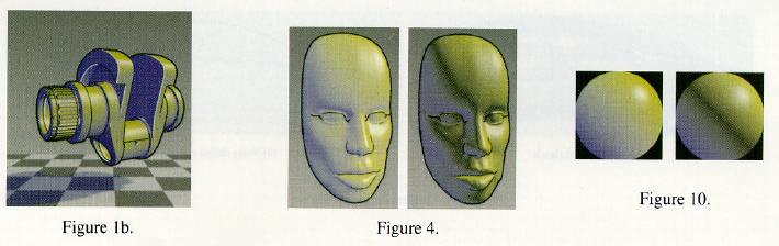
2 Figure 2: Three line conventions suggested by Martin [15]. Left: single weight used throughout the image. Middle: heavy line weight used for outer edges, other lines are thinner. Right: vary line weight to emphasize perspective. 2 Related Work Computer graphics algorithms that imitate non-photographic techniques such as painting or pen-and-ink are referred to as nonphotorealistic rendering (NPR). An underlying assumption in NPR is that artistic techniques developed by human artists have intrinsic merit based on the evolutionary nature of art. For this reason techniques are usually borrowed directly from artists rather than reinvented from first principles. The many non-photorealistic techniques used in computer graphics [3, 5, 6, 7, 13, 14, 17, 24, 28] vary greatly in their level of abstraction. Those that produce a loss of detail, like watercolor or pen-and-ink, produce a high level of abstraction. Several previous papers use a low level of abstraction which preserves precise shape properties and are thus well suited to technical illustration. Although there is a wealth of computer graphics research dealing with the display of three dimensional images, there has been little exploration into utilizing artistic techniques to aid in the conveyance of shape information in an interactive setting. Kondo et al. proposed a system based on enhancing shape recognition [11]. More recently Mochizuki et al. built a system that aids shape comprehension by rendering edge lines. Markosian et al. [14] developed algorithms for probabilistically calculating only the silhouettes for polyhedral models in real time. Rossignac et al. used the frame buffer to to render lines that enhance shape recognition [21]. There are also 3D paint programs which allow the user to experiment with non-photorealistic methods [12,25] but these methods restrict interaction and require users trained in traditional drawing and painting techniques. In contrast, our methods incorporate user interaction with automatically generated 3D technical illustrations based on geometric models. 3 Static Illustration Principles Human-drawn technical illustrations are usually stand-alone images from a single viewpoint presented on a non-stereo medium such as pen on paper. In this section we discuss the components of such illustrations that we use in a computer graphics context: line character, shading, and shadowing. 3.1 Lines in Technical Illustration Several researchers [5, 6, 14, 23] examined which lines should be drawn in a computer generated image to maximize the amount of information conveyed while minimizing the number of lines drawn. They observed that illustrators use edge lines, consisting of surface boundaries, silhouettes, discontinuities, and creases to separate individual parts and to suggest important features in the shape of each Figure 3: Left: Illustrators sometimes use the convention of white interior edge lines to produce a highlight. Image copyright 1995 Macmillan [22]. Used by permission. Right: An image produced by our system, including shading, silhouettes and white crease lines. object. These static images represented edge lines with black lines of uniform weight. There are many line weight conventions which the illustrator chooses among based on the intent of the image. Martin [15] discusses three common conventions, shown in Figure 2: a single line weight used throughout the image, two line weights with the heavier describing the outer edges, and varying the line weight along a single line emphasizing the perspective of the drawing with heavy lines in the foreground. One way of achieving the latter effect in raster graphics is to vary the line weight dependent upon the direction of the light source or in an user specified direction, giving a shadowed effect to the line. Most illustrators use bold external lines, with thinner interior lines, which aid in the perception of spaces [4]. In almost all illustrations, edge lines are drawn in black. Occasionally, if the illustration incorporates shading another convention is used in which some of the interior lines are drawn in white like a highlight. Lines drawn in black and white suggest a light source and denote the models orientation. For example, Figure 3 compares an illustration produced by an artist and an image from our system in which white creases are drawn. 3.2 Shading Shading is rendered using one of three modes. The first two are the diffuse and metallic shading models presented by Gooch et al. [6]. In its simplest form the diffuse cool to warm shading model interpolates from a cool (blue-green) to a warm (yellow-orange) color based on the surface normal. This cool-to-warm diffuse shading is shown in Figure 4a. The third method is an adaptation of this cool to warm shading, simulating the more dramatic shading effects sometimes used by artists. Figure 4b illustrates the effect achieved when the reflected light from the left of the object produces a back-splash of light opposite the direct lighting source. This is accomplished by modifying the model of [6] with a simple multiplier: where cr and p are free parameters which, for this image, are set to 0.76 and 0.78, respectively.


3 (a) Shading by Gooch et al. (b) Shading with splash back Figure 5: Left: Model with cool to warm shading with lights positioned up and to the right. Middle: After the camera position is moved to view the side of the model. Right: After moving the object instead of the camera, allowing the surface to vary completely from cool to warm. (See Color Plate) Figure 4: The dark banding in the light splash back model can communicate more curvature information and works well on organic models. (See Color Plate) 3.3 Shadowing Illustrators only include shadows when they do not occlude detail in other parts of the object [15, 16, 22]. In 3D interactive illustrations, adding only a drop shadow on a ground plane, not the shadows that an object may cast onto itself, provide helpful visual clues without occluding important details on the object. It is probably not important that these shadows be highly accurate to provide valuable information about three-dimensional structure, especially the spatial layout of a scene [10, 27]. We provide the option to display one of three types of shadow which will be discussed in Section 5.3, as well as the option to make the shadow colored, as done by many artists [19]. 4 Dynamic Illustration Principles The question remains, how do the 2D illustration rules change for an interactive 3D technical illustration? Adapting the shading and line conventions presented earlier is fairly straightforward as long as the line weight conventions have frame-to-frame coherence. The more interesting issues depend upon changing the viewer s position versus moving the object. Since there are no relevant protocols in traditional illustration, we may want to base these 3D illustration conventions on how one would move real objects. This has an effect on how the light changes with respect to the object, the light position can be specified as relative to the object or to the viewer. 4.1 Viewer Versus Object Motion The shading models presented in Section 3.2 are used to full advantage if the surface color varies completely from cool to warm. This involves moving the object and not the viewpoint or the light. As seen in Figure 5, moving the object while holding the camera and light positions constant presents more shape information and surface detail. For this reason our interface rotates the object rather than the viewer, leaving the background, light, and viewer in place. When multiple objects appear in a scene, illustrators often use different shading across each object, inferring that each object has Figure 6: Metal-shaded object with shadow and ground plane. White creases and black silhouette lines are also drawn. its own light, which does not affect other objects in the environment, similar to the virtual lights described by Walter et al. [26]. For example, two objects in a scene may be lit differently to draw attention to different attributes of each object. If this were accomplished by adding two lights to the environment, the multiple highlights would be confusing. 4.2 Material Properties Most material properties are nearly constant as the view direction or lighting changes. However, the metal shading presented by Gooch et al. is the replication of the anisotropic reflection [8] due to the surface of an object and the reflection of the environment. When a real metal part is rotated in one s hand, the banding does not stick to the object, but remains constant since the environment is not changing. However, in an interactive environment it may be too jarring to have the metal shading change abruptly. Using a metal texture would be more appropriate and a metal texture in an interactive environment would still properly convey the material property. 5 Implementation As outlined in the previous two sections, our system needs the capability to interactively display a custom shading model, silhouettes, and interior edges. In addition, this interaction must be possible for 33
 Figure 7: Adding the silhouettes to the environment map instead of calculating silhouettes from the geometry produces interesting artistic")
4 In a polyhedral model, a silhouette is an edge that is connected to both a front facing and a back facing polygon. The following is pseudo code for the basic algorithm: (a) Figure 7: Adding the silhouettes to the environment map instead of calculating silhouettes from the geometry produces interesting artistic effects. (See Color Plate) complex geometric models. In this section we describe a variety of techniques for achieving these goals, and describe the tradeoffs involved in choosing a particular technique. 5.1 Displaying Important Edges and Silhouettes To draw silhouettes, we have implemented several methods of extracting and displaying edge lines from polyhedral models, which we discuss in Section and These methods can be roughly broken down into two categories. The first assumes no prior knowledge or preprocessing of the model and heavily leverages commodity graphics hardware. The second set of methods use preprocessing of the model and are purely software algorithms. Both hardware and software algorithms clearly have a place. The set of hardware methods are useful because of ease of implementation. The software methods are advantageous due to their flexibility and lower computational complexity. All of the software methods assume that the models are either manifold or manifold with boundary Ẇe can also extract boundary curves, edges adjacent to only a single face, and creases, that is, the edge between two front facing polygons whose dihedral angle is above some threshold. The user is provided the option to draw these edges, dependent upon the model and intent of the image. The computation and drawing of creases is discussed in Section l Hardware Methods Using multi-pass rendering [1] there are several ways to extract silhouettes. The algorithm presented in the SIGGRAPH 1998 OpenGL Course does not capture internal silhouette edges and requires four passes of rendering. We recently found out that there is concurrent work similar in spirit to our hardware methods [2]. Below we provide algorithms which require two or three rendering passes and capture internal silhouettes. (b) To draw lines over polygons, the PolygonOffset extension (or PolygonOffset function in GL 1.1) [18] is needed. This function effectively modifies the depth values of the first pass based on the slope of the triangles and a bias factor. This technique can create something similar to a silhouette, effectively a halo. The depth values are pushed forward instead of back to allow lines to be rasterized over faces. Then wide lines are drawn. Where there are large discontinuities in depth (silhouettes and boundaries), only part of the line is drawn. This method requires only two passes instead of the three listed above, but can be fairly sensitive to the parameters of the polygon offset function. Using OpenGL hardware makes the implementation simple, however, it limits the thickness of the edge lines. Another hardware technique is to add the edge lines to a shading environment map as a preprocess. However, as shown in Figure 7(a), the lines lack crispness, and if the model varies greatly in curvature, there may be large black regions. In order to include silhouettes on the feet of the cow in Figure 7(b), we have to set the threshold low enough to draw lines in these high curvature regions. This causes regions which have relatively low curvature to be filled in with black. Although this effect produces some interesting, artistic results, it may be inappropriate for technical illustration Software Methods A straightforward way to draw silhouettes is to explicitly test every edge in the model. We compute an edge structure based on the face normals of the model, which are also used for back face culling as in Zhang et al. [29]. An edge is a silhouette edge if and only if: where v is a vertex on the edge, e is the eye point, and n i are the outward facing surface normal vectors of the two faces sharing the edge. This situation only occurs when one face is front facing and the other is back facing. While this computation is simple, it can potentially become a bottleneck with large models. Since we have to shade (or prime the z buffer for hidden surface elimination) this computation can be done in parallel while the model is being rendered. We use a more complex preprocess and search algorithm when classifying edges becomes a bottleneck. This algorithm is similar in spirit to Zhang et al. [29], but requires looking at arcs on the Gauss map instead of points. The Gauss map of an edge on a polyhedral model is a great arc on the sphere of orientations (Figure 8). Under orthographic projection, a plane through the origin in this sphere defines the view. All of the faces on one side of the plane are front facing, and on the other side they are back facing. If the arc corresponding to an edge is intersected by this plane, it is a silhouette edge. To search for such edge/plane intersections, we store the arcs in a hierarchy on the sphere to quickly cull edges that can not be silhouettes. We have implemented a decomposition of the sphere starting with a platonic solid (octahedron or icosahedron) and all successive levels are four to one splits of spherical triangles. An arc is stored at the lowest possible level of the hierarchy. This makes silhouette extraction logarithmic in the number of edges for smooth

, and then all of the silhouette lines are drawn in black (Right), overlapping the creases. models where the arcs tend to be short.")

5 Figure 8: The arc in a Gauss map seen in 2D. The two bold line segments are faces that share a vertex. The orientations of their normals can be represented as points on the circle. The arc between those two points represents all orientations swept out between the two normals. In 3D the same reasoning applies, and the arc is an arbitrary segment on a great circle. Table 2: Hierarchy method showing the number of edges stored at each level on a Gaussian sphere for 25k-polygon crank shaft model for non-overlapping and overlapping bins. Figure 9: All creases are drawn in white (Left), and then all of the silhouette lines are drawn in black (Right), overlapping the creases. models where the arcs tend to be short. One problem with this hierarchy is that the edges of the spherical triangles on the sphere interfere with the arcs and limit how far they can be pushed down the hierarchy. The probability of being stored in a leaf node that can contain an arc of a given length decreases as the size of the triangles shrink because the boundaries of these spherical triangles become denser as you recurse. An ad hoc solution to this problem is to use multiple hierarchies, whose spherical triangles are different, and store an arc in the hierarchy with the spherical triangle with the smallest area that contains it. A more attractive alternative would be to use bins on the sphere that overlap and/or making data dependent hierarchies. Under perspective viewing, the region you have to check grows, based on planes containing the object and intersecting the eye. Building a spatial hierarchy over the model as in [29] would minimize this effect. One advantage of any software approach is that it makes it easier to implement different styles of line drawing Line Styles As discussed in Section 3.1, line width can appear to change by either shading the lines based on the surface orientation, or by using OpenGL 1D texture mapping hardware to shade lines. Using a 1D texture map, there can be a relationship between the surface and a distance to a light in the scene. Fat boundary lines can be drawn with either the software or hardware methods. These lines are drawn after the rest of the model has been drawn (shading, creases, silhouettes). While the earlier phases are drawn, they set a stencil bit, indicating that the given pixel has been draw for this frame. Finally, the boundary silhouettes are drawn over again with wider lines. In hardware this requires a full traversal of the front or back faces, while using software extraction algorithms only require a traversal of the silhouette edges which have been previously computed. All of these algorithms are more efficient than the methods mentioned in the OpenGL course [l] because it required four rendering passes while these algorithms require only one extra pass, and that pass may only be of the silhouette edges. Creases are extracted independent of the view and are drawn as white lines. After adding shading and silhouettes, only the creases that are connected to two front facing faces, and are not already silhouettes, are visible. To emulate the look of illustrations the creases need to be drawn with the same thickness as the silhouettes, as shown in Figure 9. One problem when rendering rasterized wide lines is the gaps where the lines do not overlap. A solution to this is to render the end of the lines with large points, effectively filling in the gaps. There is much less of a performance loss with the software extraction methods, since they only need to redraw the actual silhouettes, not the entire model Discussion Silhouette finding using specialized graphics hardware like OpenGL is simple to implement and not as dependent on clean models. However it is less flexible and does not allow the user to change line weight. The software methods we discussed are more complex and depend on clean models which must have shared vertices, otherwise internal boundaries can not be checked for silhouettes. However the software methods provide more flexibility and, potentially, better performance. Table 1 presents the information of two extreme cases. These cases are based on orthographic views. Under perspective projection some form of bounding volume hierarchy would have to be employed [29] to increase the efficiency. Both the simplified and the finely tessellated versions of the crank shaft model have many 35
 sharp features, while the sphere has very small dihedral angles.")
6 (a) Environment map used to generate Figure 4(a). (b) Environment map used to generate Figure 4(b). Figure 10: Shaded sphere images used for environment maps. (See Color Plate) sharp features, while the sphere has very small dihedral angles. The current implementation of the hierarchy method uses an icosahedron with four levels of subdivision which generates 1280 faces. On the sphere this method is extremely efficient. When using overlapping bins, all of the edges are stored in the leaf nodes. When using non-overlapping bins only 84% of the edges are in the leaf nodes and 2132 are on level zero. Table 2 shows the number of edges stored at every level of the hierarchy for non-overlapping and overlapping hierarchies. The overlapping method did a much better job, even on the simplified crank model. Parallelizing the silhouette extraction with the rest of the rendering can cause the extraction time to be negligible. A separate thread can extract silhouettes while the polygons are being rendered to shade the model or initialize the Z buffer. This parallelization takes only three-thousands of a second for the sphere and five onehundredths on the large crank shaft model. If you are using software visibility algorithms this technique would probably prove to be more effective. 5.2 Shading There are several ways to apply NPR shading models using hardware [6, 1]. We chose to use environment maps because they provide the most flexibility in the shading model. This effectively allows us to evaluate a lighting model at every normal/reflection direction in the visible hemisphere in eye-space. We evaluated the whole shading equation in a Phong environment map. In using an environment map as shown in Figure 10, all normals in eye-space are mapped to a 2D texture. This shading only is valid in eye-space, but it is possible to extend these to viewindependent environment maps [9]. The cool-to-warm and light splashback terms mentioned in Section 3.2 are a function of the light direction and could be implemented with this representation. However, the Phong term would have to be computed for each view even though a single light source could be implemented as a single 1D texture map instead of a full 2D texture map Metal Shading The metal shading technique we use assumes a principle direction of curvature and striping occurs in an orthogonal direction. We first compute a table of random intensities where sample is: b f (T * u), where the base b is -0.1, T is a random number in [0, l] and a is 1.4. This causes the distribution be to biased towards white and black. We then filter each element in the table with each of its Figure 11: Drawing the shadow of a sphere with a spherical light source directly onto a ground plane below, traditionally each sample will render an ellipse. To get an accurate representation of the penumbra, this surface of the spherical light source needs to be sampled in 2 dimensions. With our method, each shadow is a concentric circle, requiring less samples to get the same results. neighbors using a l-5-1 weighting scheme and clamp this value to be in the range of [0,l]. We make these values periodic so there is some coherence which will remain smooth as they wrap around the model. The table is then resampled into a 1D texture map. The texture map is used as a cosine distribution because it is indexed via a dot product. The resampling makes sure the bands are uniformly distributed on a cylinder. We then render the model with this texture map. The texture matrix computes the dot product with a fixed axis orthogonal to the principle curvature direction, and remap the value into [0, 1]. This technique can be scaled in order to change the spacing of the stripes. By itself, this texture does not look convincing, therefore we add Phong highlights computed by lighting a texture map in eye space with several Phong light sources oriented in the directions of a icosahedron s vertices. A fairly large specular power, empirically around 30-50, seemed to work best with a specular coefficient of about Shadowing We draw shadows in one of three modes: a shadow with a hard umbra and a hard penumbra, a single hard shadow, and a soft shadow, as shown in Figure 12. Both of the later two modes approximate a spherical light source at a fixed distance from the center of the model in the direction of the light source used for shading. The simplest and fastest method to draw simple shadows is to explicitly draw an umbra and penumbra. We draw two hard shadows, one from the center of the spherical light source back in the direction used for shading, and the other forward. Soft shadows are problematic to render both accurately and efficiently, so we use an approximation to gain speed. Instead of using the conventional method to simulate an area light source, i.e., sampling the area light source and accumulating the point approximations, we project multiple shadows from the center of the approximation sampling a 1D direction, the ground plane s normal. This is done by projecting the same shadow onto a stack of planes,

7 then translating the shadows to the ground plane and accumulating them, as shown in Figure 11. Note that with this method, each sample is a perspective remapping of the first, intersected on a different plane. We could render a single shadow, copy it into texture memory and then remap it correctly to accumulate the other samples. This is much faster than projecting multiple jittered samples since there is a lower depth complexity for rasterization and a much lower burden on the transformation if the texture mapping method were used. This method assumes that the silhouette from different points on the spherical light source is the same, i.e., the projection is the same. The planes coming out of the receiver will not correctly model contact. However, you can render only the lower planes if contact occurs resulting in a less realistic shadow, but one without distracting spillover. 6 Future Work and Conclusion We have reported on an approach that produces interactive technical illustrations. This work incorporates established principles from traditional art in a framework of powerful geometric modeling and rendering. Although this work is based on empirical knowledge of human perception, a number of parameter settings are available to the user based on their aesthetic preferences. Our approach incorporates: parameters for cool and warm color choices, new interactive silhouette algorithms, various shadow schemes, line choices for internal features versus external outlines, and rendering methods exploiting texture maps. Together these produce technically informative and aesthetically pleasing interactive illustrations. This paper addresses a widely occurring need, namely, generating attractive and informative technical illustrations for modem documentation schemes, which are likely to be hierarchical and web-based for individual exploration. It represents an advance in the relatively under-developed area of computer graphics involving non-photorealistic rendering, where the needs are extensive and the available methods are few. Inspired by the work of Markosian et al's real-time probabilistic silhouette finding methods, we have taken the next step to create a system which incorporates fast deterministic silhouette and crease finding algorithms, with artistic shading and shadowing. These interactive illustrations emphasize the structure and detail of mechanical models. We believe that in the future, this approach can also be tuned for many other important domains such as medical illustration. We would also like to further explore changing line width along a single silhouette, calculating soft shadows from silhouettes, as well as creating new algorithms aimed at controlling silhouette frame-to-frame coherence. Acknowledgments Thanks to Richard Coffey, Gordon Kindlmann, the members of the University of Utah Computer Graphics groups for help in the initial stages of the paper, and to Ramesh Raskar and Michael Cohen for discussing their work in progress with us. This work was supported in part by DARPA (F C-5621) and the NSF Science and Technology Center for Computer Graphics and Scientific Visualization (ASC ). All opinions, findings, conclusions or recommendations expressed in this document are those of the author and do not necessarily reflect the views of the sponsoring agencies. 37
8 References VI PI t Betty Edwards. Drawing on the Right Side of the Brain. Jeremy P TarcherlPutnam, PI WI [71 Paul Haeberli. Paint By Numbers: Abstract Image Representation. In SIGGRAPH 90 Conference Proceedings, August PI David Blythe, Brad Grantham, Scott Nelson, and Tom McReynolds. Advanced Graphics Programming Techniques Using OpenGL Michael Cohen and Ramesh Raskar. Personal Communication Cassidy.I. Curtis, Sean E. Anderson, Kurt W. Fleischer, and David H. Salesin. Computer-Generated Watercolor. In SZG- GRAPH 97 Conference Proceedings, August Gershon Elber and Elaine Cohen. Hidden Curve Removal for Free-Form Surfaces. In SIGGRAPH 90 Conference Proceedings, August Amy Gooch, Bruce Gooch, Peter Shirley, and Elaine Cohen. A Non-photorealistic Lighting Model for Automatic Technical Illustration. In Computer Graphics, July ACM Siggraph 98 Conference Proceedings. Wolfgang Heidrich. A Model for Anisotropic Reflections in OpenGL. In SIGGRAPH 98 Conference Abstracts and Applications, page 267, July [91 Wolfgang Heidrich and Hans-Peter Seidel. View-independent environment maps. In Eurographics/SIGGRAPH Workshop on Graphics Hardware, pages 39-45, September [lo] D. Kersten, D. C. Knill, P. Mamassian, and I. Bulthoff. Illusory motion from shadows. IEEE Computer Graphics and Applications, 379(31), [ 1 l] Kunio Kondo, Fumihiko Kimura, and Taro Tajima. An Interactive Rendering Technique for 3-D Shapes. Eurographics 85, [12] Viewpoint Data Labs. LiveArt 98. Orem, UT, u91 PO1 PartNet Wakara Way Suite 216 Salt Lake City, Utah 84108, PI WI v31 ~241 Mike Salisbury, Michael T. Wong, John F. Hughes, and David H. Salesin. Orientable Textures for Image-Based Penand-Ink Illustration. In SIGGRAPH 97 Conference Proceedings, August r251 Daniel Teece. 3D Painting for Non-Photorealisitic Rendering. In SIGGRAPH 98 Conference Abstracts and Applications, page 248, July WI v Georges Winkenbach and David H. Salesin. Computer Generated Pen-and-Ink Illustration. In SIGGRAPH 94 Conference Proceedings, August ~91 Jose M. Parramon. 7 he Book of Color. Watson-Guptill Publications, New York, NY, Jarek R. Rossignac and Maarten van Emmeric. Hidden contours on a frame-buffer. Eurographics Eurographics Workshop on Computer Graphics Hardware, Tom Ruppel, editor. The Way Science Works, volume 1. MacMillan, Takafumi Saito and Tokiichiro Takahashi. Comprehensible Rendering of 3D Shapes. In SIGGRAPH 90 Conference Proceedings, August Bruce Walter, Gun Alppay, Eric P. F. Lafortune, Sebastian Femandez, and Donald P Greenberg. Fitting Virtual Lights for Non-Diffuse Walkthroughs. In SIGGRAPH 97 Conference Proceedings, pages 45-48, August Leonard R. Wanger, James A. Ferwerda, and Donald P Greenberg. Perceiving spatial relationships in computergenerated images. IEEE Computer Graphics and Applications, 12(3)&l-58, May H. Zhang and K. Hoff III. Fast backface culling using normal masks. In Proc Symposium on Interactive 30 Graphics, pages , April [13] Peter Litwinowicz. Processing Images and Video for an Impressionistic Effect. In SIGGRAPH 97 Conference Proceedings, August [ 141 L. Markosian, M. Kowalski, S. Trychin, and J. Hughes. Real- Time Non-Photorealistic Rendering. In SIGGRAPH 97 Conference Proceedings, August [15] Judy Martin. Technical Illustration: Materials, Methods, and Techniques, volume 1. Macdonald and Co Publishers, [16] Scott McCloud. Understanding Comics. Tundra Publishing Ltd., Northhampton, MA, [17] Barbara J. Meier. Painterly Rendering for Animation. In SZG- GRAPH 96 Conference Proceedings, August [18] Jackie Neider, Tom Davis, and Mason Woo. OpenGL Programming Guide. Addison-Wesley Publishing Company,


9
Image Precision Silhouette Edges
 Image Precision Silhouette Edges Ramesh Raskar * Michael Cohen + * University of North Carolina at Chapel Hill + Microsoft Research Abstract inding and displaying silhouette edges is important in applications
Non-Photorealistic Rendering
 15-462 Computer Graphics I Lecture 22 Non-Photorealistic Rendering November 18, 2003 Doug James Carnegie Mellon University http://www.cs.cmu.edu/~djames/15-462/fall03 Pen-and-Ink Illustrations Painterly
Nonphotorealism. Christian Miller CS Fall 2011
 Nonphotorealism Christian Miller CS 354 - Fall 2011 Different goals Everything we ve done so far has been working (more or less) towards photorealism But, you might not want realism as a stylistic choice
View-Dependent Particles for Interactive Non-Photorealistic Rendering
 View-Dependent Particles for Interactive Non-Photorealistic Rendering Research Paper 1 Abstract We present a novel framework for non-photorealistic rendering based on view-dependent geometric simplification
Image Precision Silhouette Edges
 Image Precision Silhouette Edges by Ramesh Raskar and Michael Cohen Presented at I3D 1999 Presented by Melanie Coggan Outline Motivation Previous Work Method Results Conclusions Outline Motivation Previous
A model to blend renderings
 A model to blend renderings Vincent Boyer and Dominique Sobczyk L.I.A.S.D.-Universit Paris 8 September 15, 2006 Abstract. We propose a model to blend renderings. It consists in mixing different kind of
Artistic Rendering of Function-based Shape Models
 Artistic Rendering of Function-based Shape Models by Shunsuke Suzuki Faculty of Computer and Information Science Hosei University n00k1021@k.hosei.ac.jp Supervisor: Alexander Pasko March 2004 1 Abstract
Practical Shadow Mapping
 Practical Shadow Mapping Stefan Brabec Thomas Annen Hans-Peter Seidel Max-Planck-Institut für Informatik Saarbrücken, Germany Abstract In this paper we propose several methods that can greatly improve
Photorealism vs. Non-Photorealism in Computer Graphics
 The Art and Science of Depiction Photorealism vs. Non-Photorealism in Computer Graphics Fredo Durand MIT- Lab for Computer Science Global illumination How to take into account all light inter-reflections
View-Dependent Particles for Interactive Non-Photorealistic Rendering
 View-Dependent Particles for Interactive Non-Photorealistic Rendering Derek Cornish 1, Andrea Rowan 2, David Luebke 2 1 2 Intrinsic Graphics University of Virginia Abstract We present a novel framework
Technical Quake. 1 Introduction and Motivation. Abstract. Michael Batchelder Kacper Wysocki
 Technical Quake Michael Batchelder mbatch@cs.mcgill.ca Kacper Wysocki kacper@cs.mcgill.ca creases and silhouettes with distance. These ideas have not yet been mentioned in literature to date that we are
Rendering Nonphotorealistic Strokes with Temporal and Arc-Length Coherence
 -.,., Rendering Nonphotorealistic Strokes with Temporal and Arc-Length Coherence Lubomir Bourdev Department of Computer Science Brown University Submitted in partial fulfillment of the requirements for
Hardware-Accelerated Interactive Illustrative Stipple Drawing of Polygonal Objects Vision, Modeling, and Visualization 2002
 Hardware-Accelerated Interactive Illustrative Stipple Drawing of Polygonal Objects Vision, Modeling, and Visualization 2002 Aidong Lu Joe Taylor Mark Hartner David Ebert Charles Hansen School of Electrical
Effectiveness of Silhouette Rendering Algorithms in Terrain Visualisation
 Effectiveness of Silhouette Rendering Algorithms in Terrain Visualisation Ruzinoor bin Che Mat Sekolah Teknologi Maklumat Universiti Utara Malaysia 06010 Sintok, Kedah Darulaman. Malaysia. ruzinoor@uum.edu.my
Real-Time Non- Photorealistic Rendering
 Real-Time Non- Photorealistic Rendering Presented by: Qing Hu LIAO SOCS, McGill Feb 1, 2005 Index Introduction Motivation Appel s Algorithm Improving Schema Rendering Result Economy of line A great deal
Non-Photo Realistic Rendering. Jian Huang
 Non-Photo Realistic Rendering Jian Huang P and NP Photo realistic has been stated as the goal of graphics during the course of the semester However, there are cases where certain types of non-photo realistic
Enhancing Information on Large Scenes by Mixing Renderings
 Enhancing Information on Large Scenes by Mixing Renderings Vincent Boyer & Dominique Sobczyk [boyer,dom]@ai.univ-paris8.fr L.I.A.S.D. - Université Paris 8 2 rue de la liberté 93526 Saint-Denis Cedex -
Real-Time Charcoal Rendering Using Contrast Enhancement Operators
 Real-Time Charcoal Rendering Using Contrast Enhancement Operators Aditi Majumder and M. Gopi Department of Computer Science University of North Carolina at Chapel Hill fmajumder,gopig@cs.unc.edu Abstract.
Computer Graphics. Shadows
 Computer Graphics Lecture 10 Shadows Taku Komura Today Shadows Overview Projective shadows Shadow texture Shadow volume Shadow map Soft shadows Why Shadows? Shadows tell us about the relative locations
Graphics and Interaction Rendering pipeline & object modelling
 433-324 Graphics and Interaction Rendering pipeline & object modelling Department of Computer Science and Software Engineering The Lecture outline Introduction to Modelling Polygonal geometry The rendering
3D Silhouette Rendering Algorithms using Vectorisation Technique from Kedah Topography Map
 3D Silhouette Rendering Algorithms using Vectorisation Technique from Kedah Topography Map Ruzinoor Che Mat and Norani Nordin Fakulti Pengurusan Teknologi Universiti Utara Malaysia 06010 Sintok, Kedah
CHAPTER 1 Graphics Systems and Models 3
 ?????? 1 CHAPTER 1 Graphics Systems and Models 3 1.1 Applications of Computer Graphics 4 1.1.1 Display of Information............. 4 1.1.2 Design.................... 5 1.1.3 Simulation and Animation...........
Simple Silhouettes for Complex Surfaces
 Eurographics Symposium on Geometry Processing(2003) L. Kobbelt, P. Schröder, H. Hoppe (Editors) Simple Silhouettes for Complex Surfaces D. Kirsanov, P. V. Sander, and S. J. Gortler Harvard University Abstract
Introduction. Illustrative rendering is also often called non-photorealistic rendering (NPR)
") Introduction Illustrative rendering is also often called non-photorealistic rendering (NPR) we shall use these terms here interchangeably NPR offers many opportunities for visualization that conventional
Introduction Illustrative rendering is also often called non-photorealistic rendering (NPR) we shall use these terms here interchangeably NPR offers many opportunities for visualization that conventional
Hardware Support for Non-photorealistic Rendering
 MITSUBISHI ELECTRIC RESEARCH LABORATORIES http://www.merl.com Hardware Support for Non-photorealistic Rendering TR2001-23 May 2001 Abstract Special features such as ridges, valleys and silhouettes, of
NPR. CS 334 Non-Photorealistic Rendering. Daniel G. Aliaga
 NPR CS 334 Non-Photorealistic Rendering Daniel G. Aliaga 3D Computer Graphics Today Miraculous performance leaps Stunning price cuts Curiously low impact Games Movies * Slides courtesy of Lee Markosian
Non-Photorealistic Experimentation Jhon Adams
 Non-Photorealistic Experimentation Jhon Adams Danny Coretti Abstract Photo-realistic rendering techniques provide an excellent method for integrating stylized rendering into an otherwise dominated field
Real-time non-photorealistic rendering
 Real-time non-photorealistic rendering Lauri Siljamäki HUT Lauri.Siljamaki@hut.fi Abstract This paper summarizes techniques used for real-time non-photorealistic rendering (NPR). Currently most NPR images
Soft Planar Shadows Using Plateaus Eric Haines Autodesk, Inc. Ithaca, New York June 18, 2001
 Soft Planar Shadows Using Plateaus Eric Haines Autodesk, Inc. Ithaca, New York erich@acm.org June 18, 2001 Abstract: This paper presents an algorithm for rapidly creating and rendering soft shadows on
Computer Graphics 10 - Shadows
 Computer Graphics 10 - Shadows Tom Thorne Slides courtesy of Taku Komura www.inf.ed.ac.uk/teaching/courses/cg Overview Shadows Overview Projective shadows Shadow textures Shadow volume Shadow map Soft
12/3/2007. Non-Photorealistic Rendering (NPR) What is NPR exactly? What is NPR exactly? What is NPR exactly? What is NPR exactly?
 What is NPR exactly? What is NPR exactly? What is NPR exactly? What is NPR exactly?") Non-Photorealistic Rendering (NPR) aka. Stylized rendering, artistic rendering, expressive graphics Covers any area of graphics where the point is to consciously not produce an image that is as photorealistic
Non-Photorealistic Rendering (NPR) aka. Stylized rendering, artistic rendering, expressive graphics Covers any area of graphics where the point is to consciously not produce an image that is as photorealistic
Lecture 15: Shading-I. CITS3003 Graphics & Animation
 Lecture 15: Shading-I CITS3003 Graphics & Animation E. Angel and D. Shreiner: Interactive Computer Graphics 6E Addison-Wesley 2012 Objectives Learn that with appropriate shading so objects appear as threedimensional
Conveying 3D Shape and Depth with Textured and Transparent Surfaces Victoria Interrante
 Conveying 3D Shape and Depth with Textured and Transparent Surfaces Victoria Interrante In scientific visualization, there are many applications in which researchers need to achieve an integrated understanding
CMSC427 Advanced shading getting global illumination by local methods. Credit: slides Prof. Zwicker
 CMSC427 Advanced shading getting global illumination by local methods Credit: slides Prof. Zwicker Topics Shadows Environment maps Reflection mapping Irradiance environment maps Ambient occlusion Reflection
Nonphotorealistic Virtual Environment Navigation from Images
 Nonphotorealistic Virtual Environment Navigation from Images Hyung W. Kang Department of Mathematics and Computer Science University of Missouri - St. Louis One University Blvd. St. Louis, MO 63121, USA
Using surface markings to enhance accuracy and stability of object perception in graphic displays
 Using surface markings to enhance accuracy and stability of object perception in graphic displays Roger A. Browse a,b, James C. Rodger a, and Robert A. Adderley a a Department of Computing and Information
Let s start with occluding contours (or interior and exterior silhouettes), and look at image-space algorithms. A very simple technique is to render
, and look at image-space algorithms. A very simple technique is to render") 1 There are two major classes of algorithms for extracting most kinds of lines from 3D meshes. First, there are image-space algorithms that render something (such as a depth map or cosine-shaded model),
1 There are two major classes of algorithms for extracting most kinds of lines from 3D meshes. First, there are image-space algorithms that render something (such as a depth map or cosine-shaded model),
Computer Graphics I Lecture 11
 15-462 Computer Graphics I Lecture 11 Midterm Review Assignment 3 Movie Midterm Review Midterm Preview February 26, 2002 Frank Pfenning Carnegie Mellon University http://www.cs.cmu.edu/~fp/courses/graphics/
Computer Science 426 Midterm 3/11/04, 1:30PM-2:50PM
 NAME: Login name: Computer Science 46 Midterm 3//4, :3PM-:5PM This test is 5 questions, of equal weight. Do all of your work on these pages (use the back for scratch space), giving the answer in the space
Advanced Computer Graphics CS 563: Screen Space GI Techniques: Real Time
 Advanced Computer Graphics CS 563: Screen Space GI Techniques: Real Time William DiSanto Computer Science Dept. Worcester Polytechnic Institute (WPI) Overview Deferred Shading Ambient Occlusion Screen
Rendering Silhouettes with Virtual Lights
 Volume 20 (2001), number 4 pp. 271 282 COMPUTER GRAPHICS forum Rendering Silhouettes with Virtual Lights Domingo Martín and Juan Carlos Torres Departamento de Lenguajes y Sistemas Informáticos, Universidad
3D Programming. 3D Programming Concepts. Outline. 3D Concepts. 3D Concepts -- Coordinate Systems. 3D Concepts Displaying 3D Models
 3D Programming Concepts Outline 3D Concepts Displaying 3D Models 3D Programming CS 4390 3D Computer 1 2 3D Concepts 3D Model is a 3D simulation of an object. Coordinate Systems 3D Models 3D Shapes 3D Concepts
Topics and things to know about them:
 Practice Final CMSC 427 Distributed Tuesday, December 11, 2007 Review Session, Monday, December 17, 5:00pm, 4424 AV Williams Final: 10:30 AM Wednesday, December 19, 2007 General Guidelines: The final will
Pipeline Operations. CS 4620 Lecture Steve Marschner. Cornell CS4620 Spring 2018 Lecture 11
 Pipeline Operations CS 4620 Lecture 11 1 Pipeline you are here APPLICATION COMMAND STREAM 3D transformations; shading VERTEX PROCESSING TRANSFORMED GEOMETRY conversion of primitives to pixels RASTERIZATION
Paint by Numbers and Comprehensible Rendering of 3D Shapes
 Paint by Numbers and Comprehensible Rendering of 3D Shapes Prof. Allison Klein Announcements Sign up for 1 st presentation at end of class today Undergrads: Thinking about grad school? Still here over
Self-shadowing Bumpmap using 3D Texture Hardware
 Self-shadowing Bumpmap using 3D Texture Hardware Tom Forsyth, Mucky Foot Productions Ltd. TomF@muckyfoot.com Abstract Self-shadowing bumpmaps add realism and depth to scenes and provide important visual
Nonphotorealistic rendering
 Nonphotorealistic rendering Photorealism Computational Photography, 6.882 Bill Freeman Fredo Durand May 9, 2006 Physically realistic computer graphics rendering Images with photographic quality (eg Vermeer,
How do we draw a picture?
 1 How do we draw a picture? Define geometry. Now what? We can draw the edges of the faces. Wireframe. We can only draw the edges of faces that are visible. We can fill in the faces. Giving each object
Shading , Fall 2004 Nancy Pollard Mark Tomczak
 15-462, Fall 2004 Nancy Pollard Mark Tomczak Shading Shading Concepts Shading Equations Lambertian, Gouraud shading Phong Illumination Model Non-photorealistic rendering [Shirly, Ch. 8] Announcements Written
Real-Time Rendering (Echtzeitgraphik) Dr. Michael Wimmer
 Dr. Michael Wimmer") Real-Time Rendering (Echtzeitgraphik) Dr. Michael Wimmer wimmer@cg.tuwien.ac.at Visibility Overview Basics about visibility Basics about occlusion culling View-frustum culling / backface culling Occlusion
Real-Time Rendering (Echtzeitgraphik) Dr. Michael Wimmer wimmer@cg.tuwien.ac.at Visibility Overview Basics about visibility Basics about occlusion culling View-frustum culling / backface culling Occlusion
Pen & Ink Illustration
 Pen & Ink Illustration Georges Winkenbach David H. Salesin Presented by: Andreas Loizias Reasons To communicate complex information more effectively through abstraction Convey information better by omitting
Computer Graphics. Illumination and Shading
 Rendering Pipeline modelling of geometry transformation into world coordinates placement of cameras and light sources transformation into camera coordinates backface culling projection clipping w.r.t.
Non-photorealistic Rendering
 Non-photorealistic Rendering Art Rendering 1 From: ATI Radeon 9700 Real-Time Demos A Brief History of (Western) Painting Prehistoric Egyptian Medieval Renaissance A peak in realism Impressionism Modernism
Accelerated Ambient Occlusion Using Spatial Subdivision Structures
 Abstract Ambient Occlusion is a relatively new method that gives global illumination like results. This paper presents a method to accelerate ambient occlusion using the form factor method in Bunnel [2005]
Adaptive Point Cloud Rendering
 1 Adaptive Point Cloud Rendering Project Plan Final Group: May13-11 Christopher Jeffers Eric Jensen Joel Rausch Client: Siemens PLM Software Client Contact: Michael Carter Adviser: Simanta Mitra 4/29/13
Shading. Introduction to Computer Graphics Torsten Möller. Machiraju/Zhang/Möller/Fuhrmann
 Shading Introduction to Computer Graphics Torsten Möller Machiraju/Zhang/Möller/Fuhrmann Reading Chapter 5.5 - Angel Chapter 6.3 - Hughes, van Dam, et al Machiraju/Zhang/Möller/Fuhrmann 2 Shading Illumination
Shadow Rendering EDA101 Advanced Shading and Rendering
 Shadow Rendering EDA101 Advanced Shading and Rendering 2006 Tomas Akenine-Möller 1 Why, oh why? (1) Shadows provide cues about spatial relationships among objects 2006 Tomas Akenine-Möller 2 Why, oh why?
Chapter 5. Projections and Rendering
 Chapter 5 Projections and Rendering Topics: Perspective Projections The rendering pipeline In order to view manipulate and view a graphics object we must find ways of storing it a computer-compatible way.
Computer Graphics (CS 543) Lecture 10: Soft Shadows (Maps and Volumes), Normal and Bump Mapping
 Lecture 10: Soft Shadows (Maps and Volumes), Normal and Bump Mapping") Computer Graphics (CS 543) Lecture 10: Soft Shadows (Maps and Volumes), Normal and Bump Mapping Prof Emmanuel Agu Computer Science Dept. Worcester Polytechnic Institute (WPI) Shadow Buffer Theory Observation:
Computer Graphics (CS 543) Lecture 10: Soft Shadows (Maps and Volumes), Normal and Bump Mapping Prof Emmanuel Agu Computer Science Dept. Worcester Polytechnic Institute (WPI) Shadow Buffer Theory Observation:
Pipeline Operations. CS 4620 Lecture 14
 Pipeline Operations CS 4620 Lecture 14 2014 Steve Marschner 1 Pipeline you are here APPLICATION COMMAND STREAM 3D transformations; shading VERTEX PROCESSING TRANSFORMED GEOMETRY conversion of primitives
Hardware Support for Non-photorealistic Rendering
 Hardware Support for on-photorealistic Rendering Ramesh Raskar MERL, Mitsubishi Electric Research Labs Abstract Special features such as ridges, valleys and silhouettes, of a polygonal scene are usually
Chapter 7 - Light, Materials, Appearance
 Chapter 7 - Light, Materials, Appearance Types of light in nature and in CG Shadows Using lights in CG Illumination models Textures and maps Procedural surface descriptions Literature: E. Angel/D. Shreiner,
Point based Rendering
 Point based Rendering CS535 Daniel Aliaga Current Standards Traditionally, graphics has worked with triangles as the rendering primitive Triangles are really just the lowest common denominator for surfaces
Shadow Algorithms. CSE 781 Winter Han-Wei Shen
 Shadow Algorithms CSE 781 Winter 2010 Han-Wei Shen Why Shadows? Makes 3D Graphics more believable Provides additional cues for the shapes and relative positions of objects in 3D What is shadow? Shadow:
Lecture 17: Shadows. Projects. Why Shadows? Shadows. Using the Shadow Map. Shadow Maps. Proposals due today. I will mail out comments
 Projects Lecture 17: Shadows Proposals due today I will mail out comments Fall 2004 Kavita Bala Computer Science Cornell University Grading HW 1: will email comments asap Why Shadows? Crucial for spatial
Overview. A real-time shadow approach for an Augmented Reality application using shadow volumes. Augmented Reality.
 Overview A real-time shadow approach for an Augmented Reality application using shadow volumes Introduction of Concepts Standard Stenciled Shadow Volumes Method Proposed Approach in AR Application Experimental
Photorealistic 3D Rendering for VW in Mobile Devices
 Abstract University of Arkansas CSCE Department Advanced Virtual Worlds Spring 2013 Photorealistic 3D Rendering for VW in Mobile Devices Rafael Aroxa In the past few years, the demand for high performance
Level of Details in Computer Rendering
 Level of Details in Computer Rendering Ariel Shamir Overview 1. Photo realism vs. Non photo realism (NPR) 2. Objects representations 3. Level of details Photo Realism Vs. Non Pixar Demonstrations Sketching,
Physically-Based Laser Simulation
 Physically-Based Laser Simulation Greg Reshko Carnegie Mellon University reshko@cs.cmu.edu Dave Mowatt Carnegie Mellon University dmowatt@andrew.cmu.edu Abstract In this paper, we describe our work on
Graphics Hardware and Display Devices
 Graphics Hardware and Display Devices CSE328 Lectures Graphics/Visualization Hardware Many graphics/visualization algorithms can be implemented efficiently and inexpensively in hardware Facilitates interactive
Introduction to Computer Graphics
 Introduction to Computer Graphics James D. Foley Georgia Institute of Technology Andries van Dam Brown University Steven K. Feiner Columbia University John F. Hughes Brown University Richard L. Phillips
Real-Time Painterly Rendering for MR Applications
 Real-Time Painterly Rendering for MR Applications Michael Haller Upper Austria University of Applied Sciences Media Technology and Design, Austria Daniel Sperl Upper Austria University of Applied Sciences
COMP30019 Graphics and Interaction Rendering pipeline & object modelling
 COMP30019 Graphics and Interaction Rendering pipeline & object modelling Department of Computer Science and Software Engineering The Lecture outline Introduction to Modelling Polygonal geometry The rendering
Lecture outline. COMP30019 Graphics and Interaction Rendering pipeline & object modelling. Introduction to modelling
 Lecture outline COMP30019 Graphics and Interaction Rendering pipeline & object modelling Department of Computer Science and Software Engineering The Introduction to Modelling Polygonal geometry The rendering
LOD and Occlusion Christian Miller CS Fall 2011
 LOD and Occlusion Christian Miller CS 354 - Fall 2011 Problem You want to render an enormous island covered in dense vegetation in realtime [Crysis] Scene complexity Many billions of triangles Many gigabytes
Real-Time Shadows. Last Time? Today. Why are Shadows Important? Shadows as a Depth Cue. For Intuition about Scene Lighting
 Last Time? Real-Time Shadows Today Why are Shadows Important? Shadows & Soft Shadows in Ray Tracing Planar Shadows Projective Texture Shadows Shadow Maps Shadow Volumes Why are Shadows Important? Depth
Computer Graphics. Shading. Based on slides by Dianna Xu, Bryn Mawr College
 Computer Graphics Shading Based on slides by Dianna Xu, Bryn Mawr College Image Synthesis and Shading Perception of 3D Objects Displays almost always 2 dimensional. Depth cues needed to restore the third
Interactive Computer Graphics A TOP-DOWN APPROACH WITH SHADER-BASED OPENGL
 International Edition Interactive Computer Graphics A TOP-DOWN APPROACH WITH SHADER-BASED OPENGL Sixth Edition Edward Angel Dave Shreiner Interactive Computer Graphics: A Top-Down Approach with Shader-Based
Acknowledgement: Images and many slides from presentations by Mark J. Kilgard and other Nvidia folks, from slides on developer.nvidia.
 Shadows Acknowledgement: Images and many slides from presentations by Mark J. Kilgard and other Nvidia folks, from slides on developer.nvidia.com Practical & Robust Stenciled Shadow Volumes for Hardware-Accelerated
Non-Photorealistic Rendering (NPR) Christian Richardt, Rainbow Group
 Christian Richardt, Rainbow Group") Non-Photorealistic Rendering (NPR) Christian Richardt, Rainbow Group Structure in six parts 1. Definition of non-photorealistic rendering (NPR) 2. History of computer graphics: from 1970s to 1995 3. Overview
Non-Photorealistic Rendering (NPR) Christian Richardt, Rainbow Group Structure in six parts 1. Definition of non-photorealistic rendering (NPR) 2. History of computer graphics: from 1970s to 1995 3. Overview
Pipeline Operations. CS 4620 Lecture 10
 Pipeline Operations CS 4620 Lecture 10 2008 Steve Marschner 1 Hidden surface elimination Goal is to figure out which color to make the pixels based on what s in front of what. Hidden surface elimination
CSE328 Fundamentals of Computer Graphics: Concepts, Theory, Algorithms, and Applications
 CSE328 Fundamentals of Computer Graphics: Concepts, Theory, Algorithms, and Applications Hong Qin State University of New York at Stony Brook (Stony Brook University) Stony Brook, New York 11794--4400
Shadows in the graphics pipeline
 Shadows in the graphics pipeline Steve Marschner Cornell University CS 569 Spring 2008, 19 February There are a number of visual cues that help let the viewer know about the 3D relationships between objects
CEng 477 Introduction to Computer Graphics Fall 2007
 Visible Surface Detection CEng 477 Introduction to Computer Graphics Fall 2007 Visible Surface Detection Visible surface detection or hidden surface removal. Realistic scenes: closer objects occludes the
Computer Graphics. Instructor: Oren Kapah. Office Hours: T.B.A.
 Computer Graphics Instructor: Oren Kapah (orenkapahbiu@gmail.com) Office Hours: T.B.A. The CG-IDC slides for this course were created by Toky & Hagit Hel-Or 1 CG-IDC 2 Exercise and Homework The exercise
Computer Graphics Shadow Algorithms
 Computer Graphics Shadow Algorithms Computer Graphics Computer Science Department University of Freiburg WS 11 Outline introduction projection shadows shadow maps shadow volumes conclusion Motivation shadows
CS 465 Program 4: Modeller
 CS 465 Program 4: Modeller out: 30 October 2004 due: 16 November 2004 1 Introduction In this assignment you will work on a simple 3D modelling system that uses simple primitives and curved surfaces organized
Real-Time Shadows. Last Time? Textures can Alias. Schedule. Questions? Quiz 1: Tuesday October 26 th, in class (1 week from today!
 Last Time? Real-Time Shadows Perspective-Correct Interpolation Texture Coordinates Procedural Solid Textures Other Mapping Bump Displacement Environment Lighting Textures can Alias Aliasing is the under-sampling
INSPIRE: An Interactive Image Assisted Non-Photorealistic Rendering System
 INSPIRE: An Interactive Image Assisted Non-Photorealistic Rendering System Minh X. Nguyen Hui Xu Xiaoru Yuan Baoquan Chen Department of Computer Science and Engineering University of Minnesota at Twin
Real-Time Rendering of Watercolor Effects for Virtual Environments
 Real-Time Rendering of Watercolor Effects for Virtual Environments Su Ian Eugene Lei and Chun-Fa Chang Department of Computer Science, National Tsing Hua University {zenith,chang}@ibr.cs.nthu.edu.tw Abstract.
Announcements. Written Assignment 2 is out see the web page. Computer Graphics
 Announcements Written Assignment 2 is out see the web page 1 Texture and other Mappings Shadows Texture Mapping Bump Mapping Displacement Mapping Environment Mapping Watt Chapter 8 COMPUTER GRAPHICS 15-462
COMP 175: Computer Graphics April 11, 2018
 Lecture n+1: Recursive Ray Tracer2: Advanced Techniques and Data Structures COMP 175: Computer Graphics April 11, 2018 1/49 Review } Ray Intersect (Assignment 4): questions / comments? } Review of Recursive
CS 130 Final. Fall 2015
 CS 130 Final Fall 2015 Name Student ID Signature You may not ask any questions during the test. If you believe that there is something wrong with a question, write down what you think the question is trying
Art Based Rendering of Fur by Instancing Geometry
 Art Based Rendering of Fur by Instancing Geometry Abstract Richie Steigerwald In this paper, I describe a non- photorealistic rendering system that uses strokes to render fur and grass in a stylized manner
Deferred Rendering Due: Wednesday November 15 at 10pm
 CMSC 23700 Autumn 2017 Introduction to Computer Graphics Project 4 November 2, 2017 Deferred Rendering Due: Wednesday November 15 at 10pm 1 Summary This assignment uses the same application architecture
Shadow Techniques. Sim Dietrich NVIDIA Corporation
 Shadow Techniques Sim Dietrich NVIDIA Corporation sim.dietrich@nvidia.com Lighting & Shadows The shadowing solution you choose can greatly influence the engine decisions you make This talk will outline
CSE528 Computer Graphics: Theory, Algorithms, and Applications
 CSE528 Computer Graphics: Theory, Algorithms, and Applications Hong Qin State University of New York at Stony Brook (Stony Brook University) Stony Brook, New York 11794--4400 Tel: (631)632-8450; Fax: (631)632-8334
Computer Graphics 1. Chapter 7 (June 17th, 2010, 2-4pm): Shading and rendering. LMU München Medieninformatik Andreas Butz Computergraphik 1 SS2010
: Shading and rendering. LMU München Medieninformatik Andreas Butz Computergraphik 1 SS2010") Computer Graphics 1 Chapter 7 (June 17th, 2010, 2-4pm): Shading and rendering 1 The 3D rendering pipeline (our version for this class) 3D models in model coordinates 3D models in world coordinates 2D Polygons
Computer Graphics 1 Chapter 7 (June 17th, 2010, 2-4pm): Shading and rendering 1 The 3D rendering pipeline (our version for this class) 3D models in model coordinates 3D models in world coordinates 2D Polygons
Real-Time Shadows. Last Time? Schedule. Questions? Today. Why are Shadows Important?
 Last Time? Real-Time Shadows The graphics pipeline Clipping & rasterization of polygons Visibility the depth buffer (z-buffer) Schedule Questions? Quiz 2: Thursday November 2 th, in class (two weeks from
Lightcuts. Jeff Hui. Advanced Computer Graphics Rensselaer Polytechnic Institute
 Lightcuts Jeff Hui Advanced Computer Graphics 2010 Rensselaer Polytechnic Institute Fig 1. Lightcuts version on the left and naïve ray tracer on the right. The lightcuts took 433,580,000 clock ticks and