HFSS Hybrid Finite Element and Integral Equation Solver for Large Scale Electromagnetic Design and Simulation
|
|
|
- Marcia Morris
- 5 years ago
- Views:
Transcription

1 HFSS Hybrid Finite Element and Integral Equation Solver for Large Scale Electromagnetic Design and Simulation Laila Salman, PhD Technical Services Specialist 1
2 Agenda Overview of Simulation Trends and Technologies ANSYS Simulation Technologies Overview ANSYS Electromagnetic Simulation Techniques: HFSS-FEM HFSS-IE New in v12 Hybrid FE-BI New in v13 Hybrid IE-Regions Physical Optics New in v14 New in v14 High Performance Computing HFSS with Domain Decomposition Method (DDM) New in v12 HFSS-IE with industry standard Message Passing Interface (MPI) Examples New in v14 2


3 Simulation Trends Full System Simulations Require simulation of more complicated and electrically large problems Efficient simulations Types of problems to solve 3


4 Ansoft Simulation Technologies Finite Element Method HFSS Efficiently handles complex material and geometries Volume based mesh and field solutions Fields are explicitly solved throughout entire volume Integral Equations HFSS-IE Efficient solution technique for open radiation and scattering Currents solved only on surface mesh Efficiency is achieved when structure is primarily metal 4 Physical Optics HFSS-IE new in v14 High frequency approximation Ideal for electrically large, smooth objects Currents are approximated in illuminated regions and set to zero in shadow regions 1 st order interactions


5 Hybrid Finite Element Integral Equations FE-BI Finite Element Method HFSS Efficiently handles complex material and geometries Integral Equations HFSS-IE Efficient solution technique for open radiating and scattering of metallic objects Hybrid Finite Element - Integral Equations FE-BI New in v13 IE-Regions New in v14 Hybrid method invoked inside of HFSS Design using IE-Regions or FE-BI boundary conditions Hybrid method takes advantage of features from both methods to allow for more efficient simulations IE-Regions 5


6 High Frequency Technique: Physical Optics Physical Optics HFSS-IE Ideal for electrically large, conducting and smooth objects High frequency asymptotic solver available inside of HFSS-IE designs Currents are approximated in illuminated regions and set to zero in shadow regions First order interaction only, single bounce Source excitation from HFSS Far Field Data-Link of incident plane wave Usage Applications include Electrically large - RCS, Antenna Placement, Reflector Analysis Quickly estimate performance of electrically large problems Full wave solution is beyond computation resources 6
7 Hybrid Methods FE-BI IE-Regions 7


8 Finite Element Boundary Integral Mesh truncation of infinite free space into a finite computational domain Alternative to ABC or PML radiation boundary conditions Hybrid solution of FEM and IE IE solution on outer faces FEM solution inside of volume FEM Solution in Volume Fields at outer surface Iterate IE Solution on Outer Surface FE-BI Advantages Arbitrary shaped boundary Conformal and discontinuous to minimize solution volume Reflection-less boundary condition High accuracy for radiating and scattering problems No theoretical minimum distance from radiator 8 Reduce simulation volume and simplify problem setup FE-BI Free space Arbitrary shape

9 Finite Element Boundary Integral: Boundary Condition Setup Enabled with HFSS-IE license feature inside of an HFSS Design Setup is similar to ABC boundary condition Enabled by selecting Model exterior as HFSS- IE domain Radiation surface must enclose entire geometry 1 infinite ground plane allowed Direct vs. Iterative Matrix Solver Direct Matrix Solver Preferred method with FE-BI Quickest solution Iterative solver Uses the least amount of RAM 9


 Elapsed Time ABC 15 70min FE-BI 7 30min")
10 Finite Element Boundary Integral: Example Problem FE-BI can be used to significantly reduce required computer resources Large volume of air inside of radome can be removed from the FEM solution domain Air volume would be required if using PML or ABC Two FE-BI surfaces will be applied Conformal to radome Conformal to horn antenna (10 GHz) FE-BI Surface 10 GHz RAM (GB) Elapsed Time ABC 15 70min FE-BI 7 30min 10 ABC FE-BI


11 IE-Regions New in v14 FEM Only Solution In a hybrid FEM-IE solution, IE Regions allow uniform regions of free space or dielectric to be removed from the FEM solution Metal objects can be solved directly with an IE solution applied to surface Removes need for air box to surround metal objects Dielectric regions can be replaced with an IE Region on the boundary of uniform dielectric material Solution inside of dielectric is solved using IE IE Region Hybrid FEM-IE Solution 11 Surface current on metal block FE-BI


12 IE-Regions: Boundary Condition Setup IE-Regions can be applied to metal or dielectric objects inside of an HFSS Design Metal Objects Typically exterior to air box region with FE-BI outer radiation boundary or Internal to dielectric IE Region Dielectric Objects Must be interior to air box region Assignment: Select Object HFSS IE Regions Assign As IE Region IE Solution Applied to Metal outside of air box and dielectric inside of air box Air Volume truncated with FE-BI radiation boundary condition 12


13 IE-Regions: Example Problem IE-Region Applied to RCS of Electricaly Large Dielectric Sphere Hybrid FEM-IE solution of scattering from dielectric sphere using IE-Regions Uniform volume of dielectric removed by applying IE-Region to surface of dielectric sphere Radius = 900mm, ε r = 4, F = 1GHz FEM Only Hybrid FEB-IE Solution IE-Region applied to dielectric Sphere FEM Only Hybrid FEM-IE 13 1 GHz RAM (GB) Elapsed Time FEM Only min Hybrid FEM-IE using IE Regions min 10X Less 7X Faster
14 Hybrid Solution With the addition of IE regions to HFSS v14, a fully hybridized solution of FEM and IE is capable of solving electrically large problems more efficiently FEM and IE FE-BI Truncate an FEM solution space with any arbitrary surface using a boundary integral IE-Regions When used along with FE-BI, conducting objects outside of FEM solution space can be solved directly with IE, eliminating the need for conducting objects to be enclosed in an air volume Homogenous dielectric volumes can be removed from the FEM solution and replaced with the equivalent IE solution in the region, useful when dielectric regions are electrically large requiring large FEM solution volume 14
15 High Performance Computing Applied to Hybrid Methods HPC with HFSS using Domain Decomposition HPC with HFSS-IE using MPI New in v14 15
16 High Performance Computing Increase simulation capacity using High Performance Computing (HPC) Domain Decomposition Method (DDM) for HFSS HFSS only HFSS using FE-BI and IE-Regions New in v14 Distributed Memory Parallel for HFSS-IE New in v14 Uses industry standard Message Passing Interface (MPI) Perform HFSS-IE simulation by distributing solution across machines in a cluster or network 16


17 High Performance Computing with HFSS using DDM Distributes mesh sub-domains to network of processors FEM volume can be subdivided into multiple domains IE Domains that are discontinuous will be distributed to separate nodes when they become large Significantly increases simulation capacity Multi-processor nodes can be utilized HPC distributes mesh sub-domains, FEM and discontinuous IE domains, to networked processors and memory 17 FEM Domain 1 FEM Domain 2 FEM Domain 3 FEM Domain 4 IE Domain
 and can perform solutions that distribute memory use across machines in a cluster or network Simulation capacity is only limited by available computer resources Enables")
18 High Performance Computing with HFSS-IE using MPI HFSS-IE uses MPI to perform a solution distributed across networked computers The HFSS-IE solver in HFSS v14 uses the industry standard Message Passing Interface (MPI) and can perform solutions that distribute memory use across machines in a cluster or network Simulation capacity is only limited by available computer resources Enables simulation of electrically large problems 18


 HFSS-IE License Hybrid or (IE/PO)")
19 HFSS v14 Licensing Configurations for Electrical Large Simulations New features in HFSS v14 enabling large scale electromagnetic design and simulation Hybrid FEM and IE Solution FE-BI and IE-Regions Requires HFSS and HFSS-IE license Distributed Memory Hybrid HFSS and HFSS-IE For Hybrid HFSS and HFSS-IE HFSS, HFSS-IE and HPC License For HFSS-IE Only HFSS-IE and HPC License Physical Optics Requires HFSS-IE license HFSS License (FEM) HFSS-IE License Hybrid or (IE/PO) Data-linked solutions DDM HPC License 19
20 Examples Finite Element - Boundary Integral IE-Region Physical Optics High Performance Computing 20


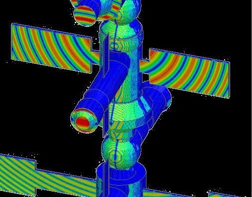
21 Array on Spacecraft Using FE-BI 7 Element Helix Antenna Array integrated on satellite platform Dielectric solar panels and antenna supports do not make this problem ideal for HFSS-IE Inclusion of solar panels create an electrically large model 64λ wide at 3.5 GHz Using ABC or PML boundary would require an Airbox equal to 21k λ 3 FE-BI can reduce the required Airbox to 1.2k λ 3 FE-BI applied to conformal Airbox ABC or PML would be applied to much larger Airbox 21
 ABC 21k λ 3 34 210 FE-BI 1.")
22 Array on Spacecraft Using FE-BI: Results Array platform integration simulated with conformal FE-BI RAM requirements reduced by 10x RAM reduction as a result of removing the surrounding free space Only possible using FE-BI Boundary Type Airbox Volume Number of Domains Total RAM (GB) ABC 21k λ FE-BI 1.2k λ X Less 22

 Full HFSS Solution Hybrid Solutions Data Link IE Solutions Data Link Physical Optics 23 Fidelity Hybrid Solution uses FEM for feed and IE applied to reflector")
23 Computer Resources Reflector Analysis Using IE-Regions Multiple techniques have been developed to analyze reflector antennas using HFSS Full HFSS Solution - Model entire solution space using only HFSS High level of fidelity also requires most computer resources Data Link Solutions Source feed excitation modeled separately from reflector Data link solutions only include 1 way coupling from source excitation to reflector Hybrid Solutions Efficient, high fidelity solution using hybrid FEM-IE techniques Full HFSS solution requires large air box (~37k λ 3 ) Full HFSS Solution Hybrid Solutions Data Link IE Solutions Data Link Physical Optics 23 Fidelity Hybrid Solution uses FEM for feed and IE applied to reflector


24 Reflector Analysis Using IE-Regions: Setup Analysis of electrically large reflector antennas may benefit from multi-step design approach utilizing several simulation methodologies Data Link Physical Optics Data Link with HFSS and Physical Optics Feed Antenna Design Data Link Full Wave Solutions Hybrid Solutions 24 HFSS to HFSS-IE or PO Data-link: Source excitation solved in HFSS Used as data linked excitation into a Physical Optics or HFSS-IE simulation Hybrid Solution - FE-BI and IE-Region Full wave simulation performed using a hybrid solution in HFSS IE-Region applied to reflector FE-BI applied around feed IE solution on reflector Hybrid FEM-IE Solution FEM solution with FE-BI
25 Reflector Analysis Using IE-Regions: Results Full wave solution possible using hybrid FEM-IE solution, enabled with FE-BI and IE-Regions Agreement between methods only show small difference in peak and side lobe levels Offset fed reflector Backscatter and blockage not fully included in either data-linked simulation effects would be more significant for center fed reflector FEM Solution with FE-BI Full Wave Solution HFSS to IE Data-Link HFSS to PO Data-Link IE solution on reflector 25


 37k λ 3 163.")
 >32X Less >10X Faster")
 5 0.")
26 Reflector Analysis Using IE-Regions: Results Hybrid FEM-IE HFSS to IE Data-Link HFSS to PO Data-Link Boundary Type Airbox Volume Total RAM (GB) Elapsed Time (hours) Full HFSS solution (FEM Only, DDM) 37k λ (1 st pass) 2.7 (1 st pass) >32X Less >10X Faster Full Wave Hybrid FEM-IE 8.6 λ 3 (Feed Only) HFSS to IE Data-Link NA HFSS to PO Data-Link NA minute 26


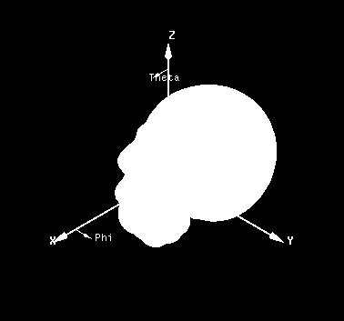
27 Hybrid Solution for Antenna Placement Analysis Using IE-Regions Antenna performance modeled with placement in proximity to human head 27 Cell phone platform and antenna with complex material properties and geometry are ideally modeled using FEM solution The uniform, high dielectric properties of the head are ideally modeled using IE solution Hybrid Solution An internal dielectric IE Region can be applied to head geometry to reduce computational size and improve efficiency FEM solution is applied remaining volume 1.8 GHz Human Head Material Properties: ε r = 79, σ= 0.47simems/m


 FEM Only 6.")
28 Hybrid Solution for Antenna Placement Analysis Using IE-Regions: Results IE-Region Boundary Condition Applied Cell Phone Only FEM Only: Cell Phone + Head Hybrid: Cell Phone + Head Hybrid FEM-IE Solution FEM Only Solution 1.8 GHz 1.8 GHz 28 Solution Type Total RAM (GB) Elapsed Time (hours) FEM Only Hybrid Solution X Less 2X Faster


29 Hybrid Solution for Antenna Placement Analysis Using IE-Regions Antenna performance modeled with placement in proximity to human head inside vehicle Cell phone platform and antenna with complex material properties and geometry are ideally modeled using FEM solution The uniform, high dielectric properties of the head are ideally modeled using IE solution The car is ideally modeled using IE-Region Hybrid Solution Setup An internal dielectric IE-Region can be applied to head geometry to reduce computational size and improve efficiency An exterior metallic IE-Region is applied to car model FEM solution around body and cell phone IE solution applied to dielectric human FEM solution is applied remaining volume body using IE-Regions 29 IE solution on car body using IE-Regions

 Elapsed")
 8 15X")


30 Hybrid Solution for Antenna Placement Analysis Using IE-Regions: Results Solution Type Total RAM (GB) Elapsed Time (hours) Full FEM Solution 160 GB (DDM) 8 15X Less 3X Faster Full FEM Solution Solution Type Total RAM (GB) Elapsed Time (hours) Hybrid FEM-IE Solution Hybrid FEM-IE Solution 30


 Elapsed Time (sec) Full Wave (HFSS-IE) 1.4 87 Physical Optics 0.")
31 Physical Optics (PO) for Electrically Large Simulations High frequency asymptotic solver Scattering and antenna placement of electrically large objects Physical Optics Full Wave Solution RCS of PEC Sphere Highlights capabilities and limitation of physical optics Creeping wave effects not accounted for by PO When electrical size of sphere becomes large, full wave solution converges with physical optics solution High Freq. Total RAM (GB) Elapsed Time (sec) Full Wave (HFSS-IE) Physical Optics Incident Wave 31 Full Wave Solution Physical Optics Solution


32 Y Tip Physical Optics for RCS of Electrically Large Structures RCS_HH Sphere PEC Physical Optics Full Wave Solution ANSOFT Good correlation between full wave solution and physical optics solution for RCS of electrically large cone-sphere Creeping wave effects not accounted for in physical optics solution Apparent as incident angles approach tip and sphere side of cone-sphere IWavePhi [deg] Full Wave Solution Physical Optics High Freq. Total RAM (GB) Elapsed Time Full Wave (HFSS-IE) hours Physical Optics minutes 32 Shadow Region


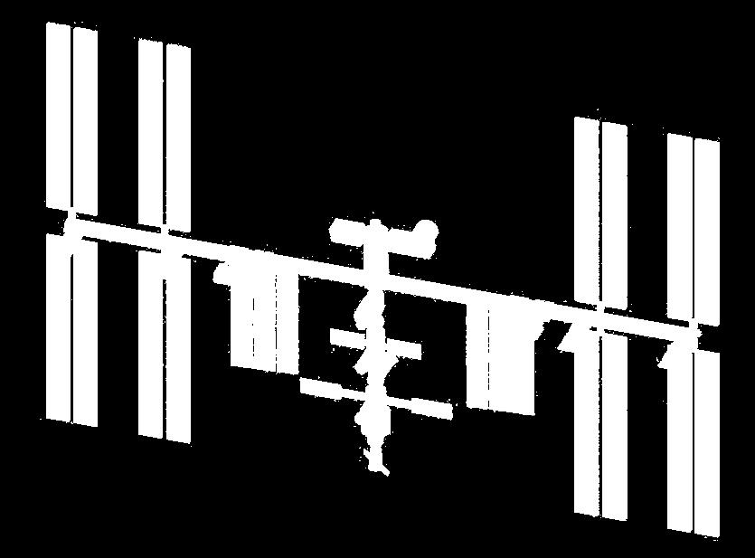
33 International Space Station (ISS): Antenna Placement and Blockage Simulations Multiple antenna and communication channels operating on and around the ISS are subject to blockage due to the large structure Physical Optics allows us to model important navigational and communications challenges Degradation of communications due to adjusting solar panels on ISS Blockage of GPS signals used by docking vehicles 110 meters 33


34 Physical Optics for S-Band Communications on ISS Antenna Blockage 2GHz Total RAM (GB) Elapsed Time (min) Physical Optics λ Source location 34

35 Distribute HFSS-IE Using MPI Full wave solution using HFSS-IE of electrically large structures RCS of fighter aircraft at 5GHz 250λ 175λ 35

 Total Time Resources 32 GB 325 GB 33.")
36 Distributed HFSS-IE Solution: Fighter Aircraft Full wave solution Scattering of fighter aircraft at 5GHz Large scale simulation possible by using compute cluster of 10 networked machines Solution only possibly using distributed computing resources Scattering Physical Optics Solution Full Wave HFSS-IE Solution Distributed HFSS-IE Solution Average Memory Total Memory (10 nodes) Total Time Resources 32 GB 325 GB 33.5 Hours 36


37 Model Electric Size Summary Data Link Physical Optics New in v14 Data Link IE Solutions HFSS-IE with HPC/MPI New in v14 Hybrid HFSS (FE-BI/IE-Region New in v14 ) Full HFSS Solution Model Material Complexity Fidelity 37
Simulation Advances. Antenna Applications
 Simulation Advances for RF, Microwave and Antenna Applications Presented by Martin Vogel, PhD Application Engineer 1 Overview Advanced Integrated Solver Technologies Finite Arrays with Domain Decomposition
Lecture 7: Introduction to HFSS-IE
 Lecture 7: Introduction to HFSS-IE 2015.0 Release ANSYS HFSS for Antenna Design 1 2015 ANSYS, Inc. HFSS-IE: Integral Equation Solver Introduction HFSS-IE: Technology An Integral Equation solver technology
Simulation Advances for RF, Microwave and Antenna Applications
 Simulation Advances for RF, Microwave and Antenna Applications Bill McGinn Application Engineer 1 Overview Advanced Integrated Solver Technologies Finite Arrays with Domain Decomposition Hybrid solving:
HFSS Ansys ANSYS, Inc. All rights reserved. 1 ANSYS, Inc. Proprietary
 HFSS 12.0 Ansys 2009 ANSYS, Inc. All rights reserved. 1 ANSYS, Inc. Proprietary Comparison of HFSS 11 and HFSS 12 for JSF Antenna Model UHF blade antenna on Joint Strike Fighter Inherent improvements in
HFSS 14 Update for SI and RF Applications Markus Kopp Product Manager, Electronics ANSYS, Inc.
 HFSS 14 Update for SI and RF Applications Markus Kopp Product Manager, Electronics ANSYS, Inc. 1 ANSYS, Inc. September 21, Advanced Solvers: Finite Arrays with DDM 2 ANSYS, Inc. September 21, Finite Arrays
HFSS PO Hybrid Region
 HFSS PO Hybrid Region Introduction The design of electrically large systems poses many challenges. Electromagnetic simulations can relatively quickly assess options and trade-offs before any physical testing.
Electromagnetics. R14 Update. Greg Pitner ANSYS, Inc. February 24, 2012
 Electromagnetics R14 Update Greg Pitner 1 HFSS Version 14 2 HFSS Overview Advanced Integrated Solver Technologies Finite Arrays with Domain Decomposition Hybrid solving: FEBI, IE Regions Physical Optics
Lecture 2: Introduction
 Lecture 2: Introduction v2015.0 Release ANSYS HFSS for Antenna Design 1 2015 ANSYS, Inc. Multiple Advanced Techniques Allow HFSS to Excel at a Wide Variety of Applications Platform Integration and RCS
HFSS 14 Update for SI and RF Applications. Presenter: Senior Application Engineer Jeff Tharp, Ph.D.
 HFSS 14 Update for SI and RF Applications Presenter: Senior Application Engineer Jeff Tharp, Ph.D. 1 Overview Advanced Integrated Solver Technologies Finite Arrays with Domain Decomposition Hybrid solving
HFSS: Optimal Phased Array Modeling Using Domain Decomposition
 HFSS: Optimal Phased Array Modeling Using Domain Decomposition 15. 0 Release Authors: Dane Thompson Nick Hirth Irina Gordion Sara Louie Presenter: Dane Thompson Motivation Electronically scannable antenna
Workshop 10-1: HPC for Finite Arrays
 Workshop 10-1: HPC for Finite Arrays 2015.0 Release ANSYS HFSS for Antenna Design 1 2015 ANSYS, Inc. Getting Started Launching ANSYS Electronics Desktop 2015 Select Programs > ANSYS Electromagnetics >
CONTENTS Preface Introduction Finite Element Formulation Finite Element Mesh Truncation
 Preface xi 1 Introduction 1 1.1 Numerical Simulation of Antennas 1 1.2 Finite Element Analysis Versus Other Numerical Methods 2 1.3 Frequency- Versus Time-Domain Simulations 5 1.4 Brief Review of Past
Powerful features (1)
") HFSS Overview Powerful features (1) Tangential Vector Finite Elements Provides only correct physical solutions with no spurious modes Transfinite Element Method Adaptive Meshing r E = t E γ i i ( x, y,
HFSS Overview Powerful features (1) Tangential Vector Finite Elements Provides only correct physical solutions with no spurious modes Transfinite Element Method Adaptive Meshing r E = t E γ i i ( x, y,
A Graphical User Interface (GUI) for Two-Dimensional Electromagnetic Scattering Problems
 for Two-Dimensional Electromagnetic Scattering Problems") A Graphical User Interface (GUI) for Two-Dimensional Electromagnetic Scattering Problems Veysel Demir vdemir@olemiss.edu Mohamed Al Sharkawy malshark@olemiss.edu Atef Z. Elsherbeni atef@olemiss.edu Abstract
A Graphical User Interface (GUI) for Two-Dimensional Electromagnetic Scattering Problems Veysel Demir vdemir@olemiss.edu Mohamed Al Sharkawy malshark@olemiss.edu Atef Z. Elsherbeni atef@olemiss.edu Abstract
HFSS - Antennas, Arrays and FSS's. David Perry Applications Engineer Ansoft Corporation
 HFSS - Antennas, Arrays and FSS's David Perry Applications Engineer Ansoft Corporation Synopsis Some Excerpts from What s New Enhancements to HFSS Wave Guide Simulator (WGS) What is it? Why you would use
Aspects of RF Simulation and Analysis Software Methods. David Carpenter. Remcom. B = t. D t. Remcom (Europe)
") Remcom (Europe) Central Boulevard Blythe Valley Park Solihull West Midlands England, B90 8AG www.remcom.com +44 870 351 7640 +44 870 351 7641 (fax) Aspects of RF Simulation and Analysis Software Methods
Remcom (Europe) Central Boulevard Blythe Valley Park Solihull West Midlands England, B90 8AG www.remcom.com +44 870 351 7640 +44 870 351 7641 (fax) Aspects of RF Simulation and Analysis Software Methods
IMPLEMENTATION OF ANALYTICAL (MATLAB) AND NUMERICAL (HFSS) SOLUTIONS ADVANCED ELECTROMAGNETIC THEORY SOHAIB SAADAT AFRIDI HAMMAD BUTT ZUNNURAIN AHMAD
 AND NUMERICAL (HFSS) SOLUTIONS ADVANCED ELECTROMAGNETIC THEORY SOHAIB SAADAT AFRIDI HAMMAD BUTT ZUNNURAIN AHMAD") STUDY OF SCATTERING & RESULTANT RADIATION PATTERN: INFINITE LINE CURRENT SOURCE POSITIONED HORIZONTALLY OVER A PERFECTLY CONDUCTING INFINITE GROUND PLANE IMPLEMENTATION OF ANALYTICAL (MATLAB) AND NUMERICAL
STUDY OF SCATTERING & RESULTANT RADIATION PATTERN: INFINITE LINE CURRENT SOURCE POSITIONED HORIZONTALLY OVER A PERFECTLY CONDUCTING INFINITE GROUND PLANE IMPLEMENTATION OF ANALYTICAL (MATLAB) AND NUMERICAL
CECOS University Department of Electrical Engineering. Wave Propagation and Antennas LAB # 1
 CECOS University Department of Electrical Engineering Wave Propagation and Antennas LAB # 1 Introduction to HFSS 3D Modeling, Properties, Commands & Attributes Lab Instructor: Amjad Iqbal 1. What is HFSS?
Ansoft HFSS 3D Boundary Manager
 and Selecting Objects and s Menu Functional and Ansoft HFSS Choose Setup / to: Define the location of ports, conductive surfaces, resistive surfaces, and radiation (or open) boundaries. Define sources
SIMULATION OF AN IMPLANTED PIFA FOR A CARDIAC PACEMAKER WITH EFIELD FDTD AND HYBRID FDTD-FEM
 1 SIMULATION OF AN IMPLANTED PIFA FOR A CARDIAC PACEMAKER WITH EFIELD FDTD AND HYBRID FDTD- Introduction Medical Implanted Communication Service (MICS) has received a lot of attention recently. The MICS
RCS Measurement and Analysis of Rectangular and Circular Cross-section Cavities
 RCS Measurement and Analysis of Rectangular and Circular Cross-section Cavities Abhinav Bharat, M L Meena, S. Sunil Kumar, Neha Sangwa, Shyam Rankawat Defence Laboratory, DRDO Jodhpur, India-342011 Abstract
Insights into EMC Chamber Design:
 Insights into EMC Chamber Design: How to achieve an optimized chamber for accurate EMC Measurements Zubiao Xiong, PhD zubiao.xiong@ets-lindgren.com November 16, 2017 EMC Compliance Testing Emission (Disturbance)
Using Sonnet in a Cadence Virtuoso Design Flow
 Using Sonnet in a Cadence Virtuoso Design Flow Purpose of this document: This document describes the Sonnet plug-in integration for the Cadence Virtuoso design flow, for silicon accurate EM modelling of
INTRODUCTION TO The Uniform Geometrical Theory of Diffraction
 INTRODUCTION TO The Uniform Geometrical Theory of Diffraction D.A. McNamara, C.W.I. Pistorius J.A.G. Malherbe University of Pretoria Artech House Boston London CONTENTS Preface xiii Chapter 1 The Nature
Advanced Surface Based MoM Techniques for Packaging and Interconnect Analysis
 Electrical Interconnect and Packaging Advanced Surface Based MoM Techniques for Packaging and Interconnect Analysis Jason Morsey Barry Rubin, Lijun Jiang, Lon Eisenberg, Alina Deutsch Introduction Fast
LAB # 3 Wave Port Excitation Radiation Setup & Analysis
 COMSATS Institute of Information Technology Electrical Engineering Department (Islamabad Campus) LAB # 3 Wave Port Excitation Radiation Setup & Analysis Designed by Syed Muzahir Abbas 1 WAVE PORT 1. New
Modeling the Acoustic Scattering from Axially Symmetric Fluid, Elastic, and Poroelastic Objects due to Nonsymmetric Forcing Using COMSOL Multiphysics
 Modeling the Acoustic Scattering from Axially Symmetric Fluid, Elastic, and Poroelastic Objects due to Nonsymmetric Forcing Using COMSOL Multiphysics Anthony L. Bonomo *1 and Marcia J. Isakson 1 1 Applied
Simulation of Spherical Luneburg Lens Using Numerical Electrodynamic Methods
 Simulation of Spherical Luneburg Lens Using Numerical Electrodynamic Methods Alexey N. Korotkov Ural Federal University named after the first President of Russia B.N. Yeltsin Yekaterinburg, Russia Name
ANSYS Improvements to Engineering Productivity with HPC and GPU-Accelerated Simulation
 ANSYS Improvements to Engineering Productivity with HPC and GPU-Accelerated Simulation Ray Browell nvidia Technology Theater SC12 1 2012 ANSYS, Inc. nvidia Technology Theater SC12 HPC Revolution Recent
Workshop 3-1: Coax-Microstrip Transition
 Workshop 3-1: Coax-Microstrip Transition 2015.0 Release Introduction to ANSYS HFSS 1 2015 ANSYS, Inc. Example Coax to Microstrip Transition Analysis of a Microstrip Transmission Line with SMA Edge Connector
ERMES: NUMERICAL TOOL FOR SAR COMPUTATIONS
 PROJECT NAME: 04-161 SMART Antennas ERMES: NUMERICAL TOOL FOR SAR COMPUTATIONS SAR TOOL VALIDATION REPORT Project SMART - WP6 Task 6.5 Deliverable 6.5.3 Rubén Otín rotin@cimne.upc.edu CIMNE - International
Design of Electromagnetic Test Sites
 Sensor and Simulation Notes Note 533 3 August 2008 Design of Electromagnetic Test Sites Carl E. Baum University of New Mexico Department of Electrical and Computer Engineering Albuquerque New Mexico 87131
MRI Induced Heating of a Pacemaker. Peter Krenz, Application Engineer
 MRI Induced Heating of a Pacemaker Peter Krenz, Application Engineer 1 Problem Statement Electric fields generated during MRI exposure are dissipated in tissue of the human body resulting in a temperature
An Introduction to the Finite Difference Time Domain (FDTD) Method & EMPIRE XCcel
 Method & EMPIRE XCcel") An Introduction to the Finite Difference Time Domain (FDTD) Method & EMPIRE XCcel Simulation Model definition for FDTD DUT Port Simulation Box Graded Mesh six Boundary Conditions 1 FDTD Basics: Field components
An Introduction to the Finite Difference Time Domain (FDTD) Method & EMPIRE XCcel Simulation Model definition for FDTD DUT Port Simulation Box Graded Mesh six Boundary Conditions 1 FDTD Basics: Field components
A systematic approach to the analysis of polarisation-sensitive reflectors
 A systematic approach to the analysis of polarisation-sensitive reflectors Hans-Henrik Viskum TICRA Læderstræde 34, 2. DK-1201 Copenhagen K Denmark hhv@ticra.com ABSTRACT The analysis of a polarisation-sensitive
Realize Your Product Promise HFSS
 Realize Your Product Promise HFSS Smart phone front view with electronic field displayed (left); back view with housing cut away to show internal geometry with electric field (right) Achieve high-frequency,
Session S0069: GPU Computing Advances in 3D Electromagnetic Simulation
 Session S0069: GPU Computing Advances in 3D Electromagnetic Simulation Andreas Buhr, Alexander Langwost, Fabrizio Zanella CST (Computer Simulation Technology) Abstract Computer Simulation Technology (CST)
Comparison of TLM and FDTD Methods in RCS Estimation
 International Journal of Electrical Engineering. ISSN 0974-2158 Volume 4, Number 3 (2011), pp. 283-287 International Research Publication House http://www.irphouse.com Comparison of TLM and FDTD Methods
EXAMINING THE IMPACT OF SPLIT PLANES ON SIGNAL AND POWER INTEGRITY
 EXAMINING THE IMPACT OF SPLIT PLANES ON SIGNAL AND POWER INTEGRITY Jason R. Miller, Gustavo J. Blando, Roger Dame, K. Barry A. Williams and Istvan Novak Sun Microsystems, Burlington, MA 1 AGENDA Introduction
ELECTROMAGNETIC diffraction by perfectly conducting
 IEEE TRANSACTIONS ON ANTENNAS AND PROPAGATION, VOL. 47, NO. 11, NOVEMBER 1999 1697 Oblique Scattering by a Pair of Conducting Half Planes: TM Case Jong-Won Yu and Noh-Hoon Myung Abstract An exact series
Timo Lähivaara, Tomi Huttunen, Simo-Pekka Simonaho University of Kuopio, Department of Physics P.O.Box 1627, FI-70211, Finland
 Timo Lähivaara, Tomi Huttunen, Simo-Pekka Simonaho University of Kuopio, Department of Physics P.O.Box 627, FI-72, Finland timo.lahivaara@uku.fi INTRODUCTION The modeling of the acoustic wave fields often
ECE 5318/6352 Antenna Engineering. Dr. Stuart Long. Chapter 15. Reflector Antennas
 ECE 5318/6352 Antenna Engineering Dr. Stuart Long Chapter 15 Reflector Antennas 1 GEOMETRICAL CONFIGURATIONS large flat sheet small flat sheet (wide freq. range) corner reflector (narrow freq. range) parabolic
Mie scattering off plasmonic nanoparticle
 Mie scattering off plasmonic nanoparticle Model documentation COMSOL 2009 Version: COMSOL 3.5a1 (build 3.5.0.608) Contents I. Model Overview II. Model Navigator III. Options and settings IV. Geometry modeling
Use of Simulation Software in Pre-Qualification Tests
 Use of Simulation Software in Pre-Qualification Tests RF & Hyper Europe 2009 Villepinte Yannis Braux: Senior EM Engineer CST FRANCE 1 www.cst.com Use of Simulation Software in Pre-Qualification Tests 1.
HFSS 3D Components. Steve Rousselle, ANSYS. Build, Share, Conquer Release. Release ANSYS, Inc.
 HFSS 3D Components Build, Share, Conquer 2015.0 Release Steve Rousselle, ANSYS 1 2015 ANSYS, Inc. What is a 3D Component? Exploded View Assembly of 3D Components Device 2 2015 ANSYS, Inc. Introduction
New Modelling Capabilities in Commercial Software for High-Gain Antennas
 6th European Conference on Antennas and Propagation (EUCAP) New Modelling Capabilities in Commercial Software for High-Gain Antennas Erik Jørgensen, Michael Lumholt, Peter Meincke, Min Zhou, Stig B. Sørensen,
REDESIGN AND OPTIMIZATION OF THE PAVING AL- GORITHM APPLIED TO ELECTROMAGNETIC TOOLS (INVITED PAPER)
") Progress In Electromagnetics Research B, Vol. 29, 409 429, 2011 REDESIGN AND OPTIMIZATION OF THE PAVING AL- GORITHM APPLIED TO ELECTROMAGNETIC TOOLS (INVITED PAPER) J. Moreno, M. J. Algar, I. González,
Progress In Electromagnetics Research B, Vol. 29, 409 429, 2011 REDESIGN AND OPTIMIZATION OF THE PAVING AL- GORITHM APPLIED TO ELECTROMAGNETIC TOOLS (INVITED PAPER) J. Moreno, M. J. Algar, I. González,
Enhanced Characteristic Basis Function Method for Solving the Monostatic Radar Cross Section of Conducting Targets
 Progress In Electromagnetics Research M, Vol. 68, 173 180, 2018 Enhanced Characteristic Basis Function Method for Solving the Monostatic Radar Cross Section of Conducting Targets Jinyu Zhu, Yufa Sun *,
Package on Board Simulation with 3-D Electromagnetic Simulation
 White Paper Package on Board Simulation with 3-D Electromagnetic Simulation For many years, designers have taken into account the effect of package parasitics in simulation, from using simple first-order
Recent Via Modeling Methods for Multi-Vias in a Shared Anti-pad
 Recent Via Modeling Methods for Multi-Vias in a Shared Anti-pad Yao-Jiang Zhang, Jun Fan and James L. Drewniak Electromagnetic Compatibility (EMC) Laboratory, Missouri University of Science &Technology
A MATLAB PHYSICAL OPTICS RCS PREDICTION CODE
 A MATLAB PHYSICAL OPTICS RCS PREDICTION CODE Elmo E. Garrido, Jr. and David C. Jenn Naval Postgraduate School Monterey, CA 93943 SUMMARY POFACETS is an implementation of the physical optics approximation
User s Manual for FEM-BEM Method
 NASA/CR-22-211966 User s Manual for FEM-BEM Method Version 1. Theresa Butler Lockheed Martin Corporation, Hampton, Virginia December 22 The NASA STI Program Office... in Profile Since its founding, NASA
CHAPTER 6 MICROSTRIP RECTANGULAR PATCH ARRAY WITH FINITE GROUND PLANE EFFECTS
 107 CHAPTER 6 MICROSTRIP RECTANGULAR PATCH ARRAY WITH FINITE GROUND PLANE EFFECTS 6.1 INTRODUCTION The finite ground plane effects of microstrip antennas are one of the issues for the wireless mobile communication
FEKO Tutorial I. Mohammad S. Sharawi, Ph.D. Electrical Engineering Department
 Mohammad S. Sharawi, Ph.D. Electrical Engineering Department This tutorial will get you started with FEKO. FEKO is a full-wave electromagnetic field simulator that is based on the Method of Moments (MoM).
Coupled Finite Element Method Based Vibroacoustic Analysis of Orion Spacecraft
 Coupled Finite Element Method Based Vibroacoustic Analysis of Orion Spacecraft Lockheed Martin Space Systems Company (LMSSC) Spacecraft and Launch Vehicle Dynamic Environments Workshop June 21 23, 2016
Virtual EM Inc. Ann Arbor, Michigan, USA
 Functional Description of the Architecture of a Special Purpose Processor for Orders of Magnitude Reduction in Run Time in Computational Electromagnetics Tayfun Özdemir Virtual EM Inc. Ann Arbor, Michigan,
Optimization of metallic biperiodic photonic crystals. Application to compact directive antennas
 Optimization of metallic biperiodic photonic crystals Application to compact directive antennas Nicolas Guérin Computational Optic Groups (COG) IFH, ETHZ, http://alphard.ethz.ch Keywords: 3D modeling,
For functionality and CAD/EDA import filter, see technical specifications of the CST STUDIO SUITE
 CST MICROWAVE STUDIO Technical Specification 1 May 2015 Frontend Module For functionality and CAD/EDA import filter, see technical specifications of the CST STUDIO SUITE Transient Solver Module Fast and
Abaqus Technology Brief. Sound Radiation Analysis of Automobile Engine Covers
 Sound Radiation Analysis of Automobile Engine Covers Abaqus Technology Brief TB-06-COVER-2 Revised: April 2007. Summary A methodology to study the sound radiation of engine valve covers is presented. The
Introduction to the FEKO Suite
 Introduction to the FEKO Suite FEKO is a suite of tools that is used for electromagnetic field analysis of 3D structures. It offers several state-of-the-art numerical methods for the solution of Maxwell
INVESTIGATIONS ON THE ANALYSIS AND DESIGN OF APERIODIC FREQUENCY SELECTIVE SURFACES FOR SPACE APPLICATIONS
 INVESTIGATIONS ON THE ANALYSIS AND DESIGN OF APERIODIC FREQUENCY SELECTIVE SURFACES FOR SPACE APPLICATIONS M. Zhou 1, S. B. Sørensen 1, N. Vesterdal 1, R. Dickie 2, R. Cahill 2, and G. Toso 3 1 TICRA,
Plane wave in free space Exercise no. 1
 Plane wave in free space Exercise no. 1 The exercise is focused on numerical modeling of plane wave propagation in ANSYS HFSS. Following aims should be met: 1. A numerical model of a plane wave propagating
THE concept of using a lossy material to absorb an
 40 IEEE TRANSACTIONS ON ANTENNAS AND PROPAGATION, VOL. 45, NO. 1, JANUARY 1997 A Comparison of Anisotropic PML to Berenger s PML and Its Application to the Finite-Element Method for EM Scattering Jo-Yu
user s guide High Frequency Structure Simulator electronic design automation software High Frequency Structure Simulator
 High Frequency Structure Simulator 9.0 electronic design automation software user s guide High Frequency Structure Simulator ANSOFT CORPORATION Four Station Square Suite 200 Pittsburgh, PA 15219-1119 The
Finite Element Analysis on Sound Wave Propagation into Human Head
 Finite Element Analsis on Sound Wave Propagation into Human Head The overall goal of this project is to develop an acoustic propagation model using wellunderstood and documented computational techniques
HFSS for ECAD: Package Modeling, MMIC and on-die extraction
 HFSS for ECAD: Package Modeling, MMIC and on-die extraction Alain Michel Technical Director, Europe 2010 ANSYS, Inc. All rights reserved. 1 ANSYS, Inc. Proprietary Agenda Introduction HFSS integrated Solver
Time domain construction of acoustic scattering by elastic targets through finite element analysis
 Time domain construction of acoustic scattering by elastic targets through finite element analysis Aaron Gunderson*, Blake Simon, Anthony Bonomo, Marcia Isakson Applied Research Laboratories University
Progress In Electromagnetics Research, PIER 43, , 2003
 Progress In Electromagnetics Research, PIER 43, 123 142, 2003 2D CAVITY MODELING USING METHOD OF MOMENTS AND ITERATIVE SOLVERS C.-F. Wang and Y.-B. Gan Temasek Laboratories National University of Singapore
ECE ILLINOIS. ECE 451: Ansys HFSS Tutorial. Simulate and Analyze an Example of Microstrip Line. Drew Handler, Jerry Yang October 20, 2014
 ECE ILLINOIS ECE 451: Ansys HFSS Tutorial Simulate and Analyze an Example of Microstrip Line Drew Handler, Jerry Yang October 20, 2014 Introduction ANSYS HFSS is an industry standard tool for simulating
New Approach to finding Active-element Patterns for Large Arrays
 New Approach to finding Active-element Patterns for Large Arrays Alan Larkin O Donnell Thesis submitted to the faculty of the Virginia Polytechnic Institute and State University in partial fulfillment
Contents Contents Creating a Simulation Example: A Dipole Antenna AMDS User s Guide
 Contents Contents 1 Creating a Simulation 7 Introduction 8 Data Files for Examples 8 Software Organization 9 Constructing the Geometry 10 Creating the Mesh 11 Defining Run Parameters 13 Requesting Results
Fiber Optic Communication Systems. Unit-03: Properties of Light. https://sites.google.com/a/faculty.muet.edu.pk/abdullatif
 Unit-03: Properties of Light https://sites.google.com/a/faculty.muet.edu.pk/abdullatif Department of Telecommunication, MUET UET Jamshoro 1 Refractive index Department of Telecommunication, MUET UET Jamshoro
Cost-Effective Parallel Computational Electromagnetic Modeling
 Cost-Effective Parallel Computational Electromagnetic Modeling, Tom Cwik {Daniel.S.Katz, cwik}@jpl.nasa.gov Beowulf System at PL (Hyglac) l 16 Pentium Pro PCs, each with 2.5 Gbyte disk, 128 Mbyte memory,
Outline. Darren Wang ADS Momentum P2
 Outline Momentum Basics: Microstrip Meander Line Momentum RF Mode: RFIC Launch Designing with Momentum: Via Fed Patch Antenna Momentum Techniques: 3dB Splitter Look-alike Momentum Optimization: 3 GHz Band
Analysis of Two-dimensional Scattering by a Periodic Array of Conducting Cylinders Using the Method of Auxiliary Sources
 PIERS ONLINE, VOL. 4, NO. 5, 8 51 Analysis of Two-dimensional Scattering by a Periodic Array of Conducting Cylinders Using the Method of Auxiliary Sources Naamen Hichem and Taoufik Aguili Ecole Nationale
SPARCS tool for GEO S/C charging analysis : Brief presentation and planned evolutions
 : Brief presentation and planned evolutions Jean-paul Dudon SPINE meeting, 28 sept. 2009 Brief presentation of SPARCS (SPAce charging Software) Planned evolutions 2 Industrial needs and goals (2001/2002)
FEKO Tutorial II. Mohammad S. Sharawi, Ph.D. Electrical Engineering Department
 Mohammad S. Sharawi, Ph.D. Electrical Engineering Department This tutorial will get you started with FEKO. FEKO is a full-wave electromagnetic field simulator that is based on the Method of Moments (MoM).
Nanostructures with HFSS
 . May 9 leidenberger@ifh.ee.ethz.ch / 9 Nanostructures with HFSS Patrick Leidenberger. May 9 . May 9 leidenberger@ifh.ee.ethz.ch / 9 Table of contents HFSS Features Mie Benchmark Possible Simulation Mistakes
Matematik former morgendagens satellitter
 Matematik former morgendagens satellitter Mød MATH på KU 15-11-2018 This is a footer TICRA One of the first spin-offs from Electromagnetics Institute at DTU (1971) 2 TICRA A history of excellence The global
Using the Discrete Ordinates Radiation Model
 Tutorial 6. Using the Discrete Ordinates Radiation Model Introduction This tutorial illustrates the set up and solution of flow and thermal modelling of a headlamp. The discrete ordinates (DO) radiation
RCS CALCUATIONS USING THE PHYSICAL OPTICS CODES
 RCS CALCATIONS SING THE PHYSICAL OPTICS CODES Introduction Physical optics based RCS calculations are performed by the two Matlab computer codes:. pofacets.m. pobistatic.m The first code (pofacets.m )
FEKO Mesh Optimization Study of the EDGES Antenna Panels with Side Lips using a Wire Port and an Infinite Ground Plane
 FEKO Mesh Optimization Study of the EDGES Antenna Panels with Side Lips using a Wire Port and an Infinite Ground Plane Tom Mozdzen 12/08/2013 Summary This study evaluated adaptive mesh refinement in the
Workshop 3-1: Antenna Post-Processing
 Workshop 3-1: Antenna Post-Processing 2015.0 Release ANSYS HFSS for Antenna Design 1 2015 ANSYS, Inc. Example Antenna Post-Processing Analysis of a Dual Polarized Probe Fed Patch Antenna This example is
Near-field time-of-arrival measurements for four feed-arms with a bicone switch
 EM Implosion Memos Memo 37 February 2010 Near-field time-of-arrival measurements for four feed-arms with a bicone switch Prashanth Kumar, Serhat Altunc, Carl E. Baum, Christos G. Christodoulou and Edl
Comparison of iteration convergences of SIE and VSIE for solving electromagnetic scattering problems for coated objects
 RADIO SCIENCE, VOL. 38, NO. 2, 1028, doi:10.1029/2002rs002610, 2003 Comparison of iteration convergences of SIE and VSIE for solving electromagnetic scattering problems for coated objects Cai-Cheng Lu
Ansoft HFSS Convergence
 Data Max Delta Matrix Parameters Ansoft HFSS Choose from the Executive Commands window to view information about the solution. If you have solved for a driven solution, the following window appears: Maxwell
High-Performance Computational Electromagnetic Modeling Using Low-Cost Parallel Computers
 High-Performance Computational Electromagnetic Modeling Using Low-Cost Parallel Computers July 14, 1997 J Daniel S. Katz (Daniel.S.Katz@jpl.nasa.gov) Jet Propulsion Laboratory California Institute of Technology
Lecture 15: Shading-I. CITS3003 Graphics & Animation
 Lecture 15: Shading-I CITS3003 Graphics & Animation E. Angel and D. Shreiner: Interactive Computer Graphics 6E Addison-Wesley 2012 Objectives Learn that with appropriate shading so objects appear as threedimensional
Optimisation globale de formes d antennes diélectriques :
 Optimisation globale de formes d antennes diélectriques : Couplage d un algorithme génétique avec un simulateur FDTD en 2-D A.ROLLAND, R.SAULEAU, A.BORISKIN 2, M.DRISSI anthony.rolland@univ-rennes.fr IETR,
Ansoft HFSS Version 7 Training Section 5: Boundary Module
 Ansoft HFSS Version 7 Training Section 5: Boundary Module 5-1 General Overview Synopsis Boundary Types, Definitions, and Parameters Source Types, Definitions, and Parameters Interface Layout Assigning
Modeling the Effects of Wind Turbines on Radar Returns
 Modeling the Effects of Wind Turbines on Radar Returns R. Ryan Ohs, Gregory J. Skidmore, Dr. Gary Bedrosian Remcom, Inc. State College, PA USA Abstract Wind turbines located near radar installations can
Simcenter 3D Acoustics Simulation Based Noise Reduction of Electric Machines Hermann Höfer 13. Nov. 2018
 Simcenter 3D Acoustics Simulation Based Noise Reduction of Electric Machines Hermann Höfer 13. Nov. 2018 Realize innovation. Possible modelling time line for electric machine design Powertrain Pre-sizing
New Technologies in CST STUDIO SUITE CST COMPUTER SIMULATION TECHNOLOGY
 New Technologies in CST STUDIO SUITE 2016 Outline Design Tools & Modeling Antenna Magus Filter Designer 2D/3D Modeling 3D EM Solver Technology Cable / Circuit / PCB Systems Multiphysics CST Design Tools
Antenna-Simulation of a Half-wave Dielectric Resonator filter
 Antenna-Simulation of a Half-wave Dielectric Resonator filter 1. Description A symmetric model of a dielectric resonator filter is analyzed using the Scattering parameters module of HFWorks to determine
Designing Horn Antenna utilizing FEM Symmetry Boundary Conditions
 Designing Horn Antenna utilizing FEM Symmetry Boundary Conditions If a structure has any symmetry (E or M i.e. Electric or Magnetic), the structure s physical size can be reduced symmetric plane boundary
Simulating Reflector Antenna Performance with GRASP9
 Simulating Reflector Antenna Performance with GRASP9 Bruce Veidt National Research Council of Canada bruce.veidt@nrc.ca and Walter Brisken NRAO Socorro wbrisken@aoc.nrao.edu September 2011 Opening Remarks
Simulation of Transition Radiation from a flat target using CST particle studio.
 Simulation of Transition Radiation from a flat target using CST particle studio. K. Lekomtsev 1, A. Aryshev 1, P. Karataev 2, M. Shevelev 1, A. Tishchenko 3 and J. Urakawa 1 1. High Energy Accelerator
Iterative methods for use with the Fast Multipole Method
 Iterative methods for use with the Fast Multipole Method Ramani Duraiswami Perceptual Interfaces and Reality Lab. Computer Science & UMIACS University of Maryland, College Park, MD Joint work with Nail
Results of the ray-tracing based solver BEAM for the approximate determination of acoustic backscattering from thin-walled objects
 Results of the ray-tracing based solver BEAM for the approximate determination of acoustic backscattering from thin-walled objects Ralf BURGSCHWEIGER 1 ; Ingo SCHÄFER 2 ; Martin OCHMANN 1 ; Bodo NOLTE
2008 International ANSYS Conference
 2008 International ANSYS Conference FEM AND FSI SIMULATIONS OF IMPACT LOADS ON GRP SUBSEA COMPOSITE COVERS Kjetil Rognlien, MSc Technical Consultant EDR AS, Norway 2008 ANSYS, Inc. All rights reserved.