HFSS: Optimal Phased Array Modeling Using Domain Decomposition
|
|
|
- Oswald Ryan
- 6 years ago
- Views:
Transcription

1 HFSS: Optimal Phased Array Modeling Using Domain Decomposition Release Authors: Dane Thompson Nick Hirth Irina Gordion Sara Louie Presenter: Dane Thompson


2 Motivation Electronically scannable antenna arrays often contain semiarbitrary element layouts with hundreds or thousands of elements. HFSS V15 includes new enhancements to enable easy creation and accurate/fast simulation of such finite arrays ANSYS, Inc. November 14, 2012


3 Overview Goal: To demonstrate the superior accuracy, flexibility, and speed of finite antenna array modeling in HFSS V15. MagVector PhaseVector Finite Array DDM (FA-DDM) w/febi New in v15 Array Mask with Padding Cells New in v15 MPI New in v15 Composite excitations v ANSYS, Inc. November 14, 2012
4 Outline Part I: Finite Array Domain Decomposition Overview Part II: Accuracy Part III: Flexibility Part IV: Speed/Capacity Conclusion ANSYS, Inc. November 14, 2012
5 Part I: Finite Array Domain Decomposition Overview Part I: Finite Array Domain Decomposition Overview Part II: Accuracy Part III: Flexibility Part IV: Speed/Capacity Conclusion ANSYS, Inc. November 14, 2012


6 Finite Array Domain Decomposition Utilizes Replicated DDM Unit Cell to Address Array Concerns Geometry and Mesh copied directly from Unit Cell Model Unit Cell geometry expanded to finite array through a simple GUI Adaptive Meshing Process imported from Unit Cell Simulation Dramatically reduces the meshing time associated with finite array analyses. Mesh periodicity reinforces array s periodicity ANSYS, Inc. November 14, 2012


7 Finite Array DDM Tool Advantages Advantages of the new finite array tool in V14 of HFSS: 1. Solves much BIGGER arrays on the same hardware 256 element Vivaldi with metal thickness 2. Obtains ACCURATE results that match HFSS explicit simulations 3. Enables EFFICIENT simulation of large finite arrays utilizing domain decomposition (DDM) 4. Makes it EASY to transform a master/slave unit cell into a finite array ANSYS, Inc. November 14, 2012
8 Part II: Accuracy Part I: Finite Array Domain Decomposition Overview Part II: Accuracy Part III: Flexibility Part IV: Speed/Capacity Conclusion ANSYS, Inc. November 14, 2012
9 Accuracy Goal: Demonstrate the pattern accuracy of finite array domain decomposition (DDM) Enabling feature: FEBI absorbing boundary with FA-DDM New V15 Radiation Boundary vs FEBI Primer FA-DDM Boundary Details Far-field Pattern Accuracy Comparisons ANSYS, Inc. November 14, 2012


10 Radiation Boundary: Incidence Angle Dependency Radiation boundary functions well for incident angles less than Radiation Boundary Radiation Boundary Poor absorption of radiation boundary affects radiation pattern ANSYS, Inc. November 14, 2012


11 PML Incidence Angle Dependency PML PML Blue Trace is with thicker PML PML functions well for incident angles less than Better absorption leads to better consistency in the patterns ANSYS, Inc. November 14, 2012


12 FEBI Incident Angle Dependency FEBI Hybridization FEBI Hybridization Pattern Results are Insensitive to Incidence Angle ANSYS, Inc. November 14, 2012
 Radiation Boundary on")


13 FA-DDM Side Absorbing Boundaries with PML (V14 Setup) Radiation Boundary on HFSSv14 Side Walls Can Affect Pattern Results PML Vacuum buffer region mimics FA-DDM Radiation boundary on sides ANSYS, Inc. November 14, 2012
14 FA-DDM Side Absorbing Boundaries with FEBI V15 Improved Accuracy Through FEBI Enhancements IE Solution Can to Touch the Array s Ground Plane No longer need Radiation Boundary on the Side Walls FEBI radiation boundary FEBI radiation boundary surrounding the array on five sides ANSYS, Inc. November 14, 2012


15 FA-DDM Boundary Setup FEBI radiation boundary FEBI radiation boundary surrounding the array on five sides PerfE or finite cond. w/inf Gnd option checked Infinite ground plane everywhere ANSYS, Inc. November 14, 2012


16 Accuracy Comparison Uniform 3x3 vivaldi array Test Cases: 1. Explicit with PML 2. Explicit with FEBI 3. FA-DDM with PML 4. FA-DDM with FEBI PML Explicit 1 2 FEBI Explicit All radiation surfaces are seeded at Lambda/6 for highest pattern accuracy FA-DDM w/pml FA-DDM w/febi 3 4 Surrounding air cells are not visualized with the FA-DDM display, but they are present for the solver V14 suggested setup for FA-DDM V15 improved accuracy for FA-DDM ANSYS, Inc. November 14, 2012
17 3x3 Vivaldi Array Boresight SideLobe Horizon The three setups expected to be the most accurate agree very well. Let s zoom in to see more detail ANSYS, Inc. November 14, 2012
18 3x3 Vivaldi Array Boresight Accuracy db Most accurate setups 0.01 db Boresight gain is within 0.01dB for the three setups expected to be most accurate, including the FA-DDM w/febi solution in HFSS V ANSYS, Inc. November 14, 2012
19 3x3 Vivaldi Array Sidelobe Accuracy Most accurate setups 0.05 db FA-DDM setup available in HFSS V db FA-DDM setup available in HFSS V14 Sidelobe gain is within 0.05dB for the three setups expected to be most accurate, including the FA-DDM w/febi solution in HFSS V ANSYS, Inc. November 14, 2012
20 3x3 Vivaldi Array Horizon Accuracy 0.12 db 0.79 db FA-DDM setup available in HFSS V15 FA-DDM setup available in HFSS V14 Most accurate setups Horizon gain is within 0.12dB for the three setups expected to be most accurate, including the FA-DDM w/febi solution in HFSS V ANSYS, Inc. November 14, 2012


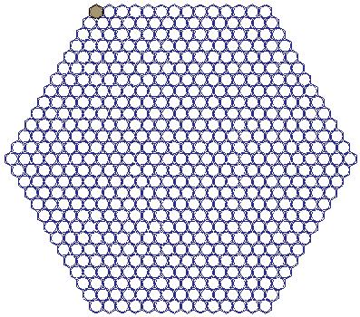
21 Accuracy Example #2 - FA-DDM vs. Explicit array 547 element hexagonal array composed of circular waveguide elements Both arrays with Lambda/6 seeding operation on radiation surfaces Phi = 0deg Cut Plane Solid: FA-DDM Circles: Explicit Phi = 90deg Cut Plane Solid: FA-DDM Circles: Explicit The explicitly solved array and FA-DDM solved array patterns are in agreement over a dynamic range of ~60dB ANSYS, Inc. November 14, 2012
22 Part III: Flexibility Part I: Finite Array Domain Decomposition Overview Part II: Accuracy Part III: Flexibility Part IV: Speed/Capacity Conclusion ANSYS, Inc. November 14, 2012
23 Flexibility Goal: Enable quick/easy generation of shaped or sparse finite arrays. Enabling feature: Array mask with padding cells New V15 Array Masks Shaped/Sparse Arrays HFSS Toolkits for Arbitrary Array Generation ANSYS, Inc. November 14, 2012


24 Array Mask in HFSS V14 vs HFSS V15 HFSS V14 Uniform cartesian grid Active or Passive HFSS V15 Padding cells enable array shaping Note the small changes in the selection dialogue ANSYS, Inc. November 14, 2012
: Element is present and is terminated in a matched load (no ports). 3. PADDING (gray cells): No element present.")
25 Array Mask Cell Types Each element in the array mask can be set to one of the three following types: New in V15 1. ACTIVE (blue cells): Element is present and has ports. 2. PASSIVE (white cells): Element is present and is terminated in a matched load (no ports). 3. PADDING (gray cells): No element present. Options: a) Air only b) Air with infinite ground Active elements ANSYS, Inc. November 14, 2012


26 Array Mask Setup 1 The array element distribution is dependent on the master/slave A and B vector directions. 2 The array mask 'A' vector direction is down. The array mask 'B' vector direction is to the right. 'A' vector direction 'B' vector direction ANSYS, Inc. November 14, 2012
 3 The master/slave pairs should be along the X and Y axes as shown to create an array that visually maps to the array mask.")
27 Array Mask Setup (cont.) 3 The master/slave pairs should be along the X and Y axes as shown to create an array that visually maps to the array mask. M1 Default top-down view. M2 S2 S1 'A' vector (red-solid) 'B' vector (blue-dotted) ANSYS, Inc. November 14, 2012


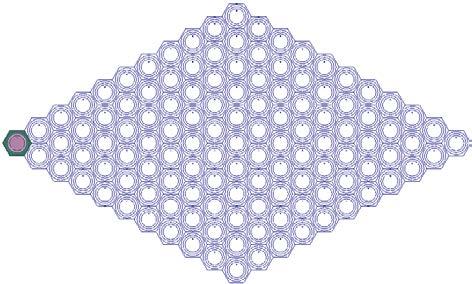
28 Flexibility Shaped Arrays Diamond Circular Oval Square/Rectangular Hexagonal Triangular/Trapezoidal ANSYS, Inc. November 14, 2012


29 Flexibility Sparse Arrays Randomized Hex Asymmetric Spiral/Hex Small Spiral Thinned Snowflake Hex Panels ANSYS, Inc. November 14, 2012

30 HFSS Toolkits New in V15 Iron Python programmable Toolkits are now available in HFSS V15 Toolkits enable users to create custom GUIs inside of HFSS with wizard like functionality Navigation to Toolkits is under HFSS > Toolkit ANSYS, Inc. November 14, 2012


31 HFSS Toolkit for Array Shape Generation 1 The Array Toolkit makes array shape generation easy! 2 In this example Toolkit, the following arrays may be generated: Hexagonal Hexagonal Random Snowflake However, the toolkit is modifiable by the user to generate ANY array type desired! 3 Also included in the toolkit is the ability to import an array mask from a.csv file 0 = Active 1 = Passive 2 = Padding ANSYS, Inc. November 14, 2012
32 Part IV: Speed/Capacity Part I: Finite Array Domain Decomposition Overview Part II: Accuracy Part III: Flexibility Part IV: Speed/Capacity Conclusion ANSYS, Inc. November 14, 2012
33 Speed Goal: Simulate large arrays faster and larger than ever before! Enabling features: 1) MPI data transfer New V15 2) Composite Excitations New V15 Composite Excitations Message Passing Interface (MPI) ANSYS, Inc. November 14, 2012
 with a defined magnitude/phase excitation vector that can be treated as a single excitation.")
34 Composite Excitations What is it? A new solution type in HFSS. How does it work? Solves a high port count iterative solver problem (such as FA-DDM) with a defined magnitude/phase excitation vector that can be treated as a single excitation. MagPort1: 1 AllOthers: 0 Solve Traditional Iterative*: MagPort2: 1 AllOthers: 0 Solve Composite: MagVector = [ ] PhaseVector = [ ] Solve MagPortN: 1 AllOthers: 0 Solve What are the benefits? Solve a subset of the scan volume MUCH more quickly than running all excitations in the array independently (but have to run again for each Edit Sources state change) *Multi-port iterative solves are multi-threaded with HPC ANSYS, Inc. November 14, 2012 Only N simultaneous ports can be solved with N cores.
35 Composite Excitations Solve Time for Varying Array Sizes Vivaldi element. Relaxed settings. Radiation boundary w/lambda/6 seeding. Array Size Solve Time [hh:mm] Full Array FA- DDM Composite Excitations FA-DDM Speedup 3x3 1:10 0:08* 9x* 4x4 1:28 0:09* 10x* 8x8 6:51 0:27* 15x* 12x12 28:39 0:42* 41x* 16x16-0:53* - 20x20-1:14* - Simulation Time [minutes] Full Array Composite Number of Antenna Elements As port counts rise into the hundreds, simulation time slows. Composite excitations allows quick extraction of one custom excitation vector to observe active s-parameters, and near-field/far-field results ANSYS, Inc. November 14, 2012 *Provides active s-parameters and pattern data at one scan angle
36 Composite Excitations Examples 1. Diamond tapered vivaldi array 2. Asymmetric hex spiral array 3. Small spiral array 4. Snowflake array 5. Large hex array ANSYS, Inc. November 14, 2012


37 Diamond Tapered Vivaldi Array Tapered Vivaldi array 15 x 16 array mask 240 total cells 128 active cells 512 excitations Boresight angle 2hr3 min 148GB distributed RAM ANSYS, Inc. November 14, 2012


38 Asymmetric Hex Spiral Array Spiral shaped 27X27 array (13 rings) 2 HPC Packs FA-DDM Composite Excitations RAM: 11.4GB Time: 8 minutes ANSYS, Inc. November 14, 2012


39 Small Spiral Array Spiral shaped 9X9 array, 25 ports, 50 modes 1HPC Pack FA-DDM Full Array Analysis RAM: 1.4GB Time: 18 minutes ANSYS, Inc. November 14, 2012


40 Small Spiral Array Spiral shaped 9X9 array, 25 ports, 50 modes Control of Sidelobe Level: Tapered feed A post-processing variable is used to sweep the magnitude taper of the array and to animate the pattern result in real time ANSYS, Inc. November 14, 2012


41 Small Spiral Array Spiral shaped 9X9 array, 25 ports, 50 modes Control of Sidebobe Level: Tapered feed Plot the tradeoff between beamwidth and sidelobe levels Plain lines = tapered magnitudes Symbol lines = uniform magnitudes Phi = 0, Phi = 90 Tapering the magnitudes yields minimal sidelobes, but a wider beamwidth and lower gain ANSYS, Inc. November 14, 2012


 Reduce element count")
 42 2012 ANSYS, Inc.")
42 Snowflake Array Snowflake shaped array, 529 circular WG elements, 1058 modes 2 HPC Packs FA-DDM Composite Excitations RAM: 62 GB (distributed) Time: 27 minutes The goals of this sparse array are to: 1) Reduce side lobe levels 2) Reduce element count for the same electrical aperture (cost) ANSYS, Inc. November 14, 2012

43 Snowflake Array Snowflake shaped array, composite excitations Sidelobes >22dB below peak 22.3dB Active S-parameters are available for the given excitation vector ANSYS, Inc. November 14, 2012

44 Snowflake Array - Animated E-field E-field 5mm above aperture Circularly polarized elements ANSYS, Inc. November 14, 2012


45 Large Hex Array Circular waveguide element, hexagonal arrays 18 rings 1027 elements 2054 modes Can HFSS solve over 1,000 elements? 38 min 105GB distributed RAM* *Solved with accurate settings ANSYS, Inc. November 14, 2012
46 MPI Simulation statistics for an 8x8 vivaldi array on V14 (with RSM) vs. V15 (with MPI) The RAM reduction is due to changes with the mesh in the air cells in V15 The solve time improvement is attributable to MPI and updated algorithmic changes. Steered beam RAM [GB] Time [hh:mm] Speedup vs. V14 V14 FiniteArrayDDM 91 28:10 - V15 FiniteArrayDDM 65 8:37 3.3x V15 Composite Excitations* Using 2 HPC Packs 63 0:29 58x* *For a single scan angle ANSYS, Inc. November 14, 2012
 Saves fields for each excitation Setup Save all fields (default)")
47 Capacity Save Radiated Fields Only Save Radiated Fields Only Option enables running large array simulations without filling up the hard disk. 8x8 Vivaldi Array 64 unit cells 4 excitations per unit cell 256 total excitations Full array simulation (not composite excitations) Saves fields for each excitation Setup Save all fields (default) Save radiated fields only Disk Space Used 589GB 2.98GB Disk Space Savings reference 198x ANSYS, Inc. November 14, 2012
48 Conclusion Part I: Accuracy Part II: Flexibility Part III: Speed/Capacity Conclusion ANSYS, Inc. November 14, 2012


49 Conclusion The new FEBI touching ground plane option enables highest accuracy far-field calculations Array masks with padding cells enable great flexibility for easily creating semi-arbitrary shaped arrays MPI and algorithmic changes have made FA-DDM simulations several times faster in HFSS V15 Composite excitations allows simulating specific scan angles of huge port count finite arrays quickly and efficiently ANSYS, Inc. November 14, 2012
50 Acronyms/Terms Acronyms DDM - Domain decomposition method FA-DDM - Finite array domain decomposition method FEBI - Finite element boundary integral PML - Perfectly matched layer MPI - Message passing interface Terms Explicit - Means the array is drawn manually without the finite array tool. Or the array is explicitly created ANSYS, Inc. November 14, 2012
Workshop 10-1: HPC for Finite Arrays
 Workshop 10-1: HPC for Finite Arrays 2015.0 Release ANSYS HFSS for Antenna Design 1 2015 ANSYS, Inc. Getting Started Launching ANSYS Electronics Desktop 2015 Select Programs > ANSYS Electromagnetics >
HFSS Hybrid Finite Element and Integral Equation Solver for Large Scale Electromagnetic Design and Simulation
 HFSS Hybrid Finite Element and Integral Equation Solver for Large Scale Electromagnetic Design and Simulation Laila Salman, PhD Technical Services Specialist laila.salman@ansys.com 1 Agenda Overview of
Simulation Advances for RF, Microwave and Antenna Applications
 Simulation Advances for RF, Microwave and Antenna Applications Bill McGinn Application Engineer 1 Overview Advanced Integrated Solver Technologies Finite Arrays with Domain Decomposition Hybrid solving:
Lecture 2: Introduction
 Lecture 2: Introduction v2015.0 Release ANSYS HFSS for Antenna Design 1 2015 ANSYS, Inc. Multiple Advanced Techniques Allow HFSS to Excel at a Wide Variety of Applications Platform Integration and RCS
Simulation Advances. Antenna Applications
 Simulation Advances for RF, Microwave and Antenna Applications Presented by Martin Vogel, PhD Application Engineer 1 Overview Advanced Integrated Solver Technologies Finite Arrays with Domain Decomposition
Powerful features (1)
") HFSS Overview Powerful features (1) Tangential Vector Finite Elements Provides only correct physical solutions with no spurious modes Transfinite Element Method Adaptive Meshing r E = t E γ i i ( x, y,
HFSS Overview Powerful features (1) Tangential Vector Finite Elements Provides only correct physical solutions with no spurious modes Transfinite Element Method Adaptive Meshing r E = t E γ i i ( x, y,
HFSS 14 Update for SI and RF Applications Markus Kopp Product Manager, Electronics ANSYS, Inc.
 HFSS 14 Update for SI and RF Applications Markus Kopp Product Manager, Electronics ANSYS, Inc. 1 ANSYS, Inc. September 21, Advanced Solvers: Finite Arrays with DDM 2 ANSYS, Inc. September 21, Finite Arrays
HFSS - Antennas, Arrays and FSS's. David Perry Applications Engineer Ansoft Corporation
 HFSS - Antennas, Arrays and FSS's David Perry Applications Engineer Ansoft Corporation Synopsis Some Excerpts from What s New Enhancements to HFSS Wave Guide Simulator (WGS) What is it? Why you would use
Lecture 7: Introduction to HFSS-IE
 Lecture 7: Introduction to HFSS-IE 2015.0 Release ANSYS HFSS for Antenna Design 1 2015 ANSYS, Inc. HFSS-IE: Integral Equation Solver Introduction HFSS-IE: Technology An Integral Equation solver technology
Electromagnetics. R14 Update. Greg Pitner ANSYS, Inc. February 24, 2012
 Electromagnetics R14 Update Greg Pitner 1 HFSS Version 14 2 HFSS Overview Advanced Integrated Solver Technologies Finite Arrays with Domain Decomposition Hybrid solving: FEBI, IE Regions Physical Optics
A Graphical User Interface (GUI) for Two-Dimensional Electromagnetic Scattering Problems
 for Two-Dimensional Electromagnetic Scattering Problems") A Graphical User Interface (GUI) for Two-Dimensional Electromagnetic Scattering Problems Veysel Demir vdemir@olemiss.edu Mohamed Al Sharkawy malshark@olemiss.edu Atef Z. Elsherbeni atef@olemiss.edu Abstract
A Graphical User Interface (GUI) for Two-Dimensional Electromagnetic Scattering Problems Veysel Demir vdemir@olemiss.edu Mohamed Al Sharkawy malshark@olemiss.edu Atef Z. Elsherbeni atef@olemiss.edu Abstract
HFSS Ansys ANSYS, Inc. All rights reserved. 1 ANSYS, Inc. Proprietary
 HFSS 12.0 Ansys 2009 ANSYS, Inc. All rights reserved. 1 ANSYS, Inc. Proprietary Comparison of HFSS 11 and HFSS 12 for JSF Antenna Model UHF blade antenna on Joint Strike Fighter Inherent improvements in
HFSS PO Hybrid Region
 HFSS PO Hybrid Region Introduction The design of electrically large systems poses many challenges. Electromagnetic simulations can relatively quickly assess options and trade-offs before any physical testing.
Workshop 3-1: Antenna Post-Processing
 Workshop 3-1: Antenna Post-Processing 2015.0 Release ANSYS HFSS for Antenna Design 1 2015 ANSYS, Inc. Example Antenna Post-Processing Analysis of a Dual Polarized Probe Fed Patch Antenna This example is
Designing Horn Antenna utilizing FEM Symmetry Boundary Conditions
 Designing Horn Antenna utilizing FEM Symmetry Boundary Conditions If a structure has any symmetry (E or M i.e. Electric or Magnetic), the structure s physical size can be reduced symmetric plane boundary
CECOS University Department of Electrical Engineering. Wave Propagation and Antennas LAB # 1
 CECOS University Department of Electrical Engineering Wave Propagation and Antennas LAB # 1 Introduction to HFSS 3D Modeling, Properties, Commands & Attributes Lab Instructor: Amjad Iqbal 1. What is HFSS?
Insights into EMC Chamber Design:
 Insights into EMC Chamber Design: How to achieve an optimized chamber for accurate EMC Measurements Zubiao Xiong, PhD zubiao.xiong@ets-lindgren.com November 16, 2017 EMC Compliance Testing Emission (Disturbance)
Advanced Surface Based MoM Techniques for Packaging and Interconnect Analysis
 Electrical Interconnect and Packaging Advanced Surface Based MoM Techniques for Packaging and Interconnect Analysis Jason Morsey Barry Rubin, Lijun Jiang, Lon Eisenberg, Alina Deutsch Introduction Fast
IMPLEMENTATION OF ANALYTICAL (MATLAB) AND NUMERICAL (HFSS) SOLUTIONS ADVANCED ELECTROMAGNETIC THEORY SOHAIB SAADAT AFRIDI HAMMAD BUTT ZUNNURAIN AHMAD
 AND NUMERICAL (HFSS) SOLUTIONS ADVANCED ELECTROMAGNETIC THEORY SOHAIB SAADAT AFRIDI HAMMAD BUTT ZUNNURAIN AHMAD") STUDY OF SCATTERING & RESULTANT RADIATION PATTERN: INFINITE LINE CURRENT SOURCE POSITIONED HORIZONTALLY OVER A PERFECTLY CONDUCTING INFINITE GROUND PLANE IMPLEMENTATION OF ANALYTICAL (MATLAB) AND NUMERICAL
STUDY OF SCATTERING & RESULTANT RADIATION PATTERN: INFINITE LINE CURRENT SOURCE POSITIONED HORIZONTALLY OVER A PERFECTLY CONDUCTING INFINITE GROUND PLANE IMPLEMENTATION OF ANALYTICAL (MATLAB) AND NUMERICAL
CONTENTS Preface Introduction Finite Element Formulation Finite Element Mesh Truncation
 Preface xi 1 Introduction 1 1.1 Numerical Simulation of Antennas 1 1.2 Finite Element Analysis Versus Other Numerical Methods 2 1.3 Frequency- Versus Time-Domain Simulations 5 1.4 Brief Review of Past
LAB # 3 Wave Port Excitation Radiation Setup & Analysis
 COMSATS Institute of Information Technology Electrical Engineering Department (Islamabad Campus) LAB # 3 Wave Port Excitation Radiation Setup & Analysis Designed by Syed Muzahir Abbas 1 WAVE PORT 1. New
An Introduction to the Finite Difference Time Domain (FDTD) Method & EMPIRE XCcel
 Method & EMPIRE XCcel") An Introduction to the Finite Difference Time Domain (FDTD) Method & EMPIRE XCcel Simulation Model definition for FDTD DUT Port Simulation Box Graded Mesh six Boundary Conditions 1 FDTD Basics: Field components
An Introduction to the Finite Difference Time Domain (FDTD) Method & EMPIRE XCcel Simulation Model definition for FDTD DUT Port Simulation Box Graded Mesh six Boundary Conditions 1 FDTD Basics: Field components
newfasant Periodical Structures User Guide
 newfasant Periodical Structures User Guide Software Version: 6.2.10 Date: February 23, 2018 Index 1. FILE MENU 2. EDIT MENU 3. VIEW MENU 4. GEOMETRY MENU 5. MATERIALS MENU 6. CELL MENU 6.1. DEFINE CELL
FEKO Mesh Optimization Study of the EDGES Antenna Panels with Side Lips using a Wire Port and an Infinite Ground Plane
 FEKO Mesh Optimization Study of the EDGES Antenna Panels with Side Lips using a Wire Port and an Infinite Ground Plane Tom Mozdzen 12/08/2013 Summary This study evaluated adaptive mesh refinement in the
Workshop 3-1: Coax-Microstrip Transition
 Workshop 3-1: Coax-Microstrip Transition 2015.0 Release Introduction to ANSYS HFSS 1 2015 ANSYS, Inc. Example Coax to Microstrip Transition Analysis of a Microstrip Transmission Line with SMA Edge Connector
New Technologies in CST STUDIO SUITE CST COMPUTER SIMULATION TECHNOLOGY
 New Technologies in CST STUDIO SUITE 2016 Outline Design Tools & Modeling Antenna Magus Filter Designer 2D/3D Modeling 3D EM Solver Technology Cable / Circuit / PCB Systems Multiphysics CST Design Tools
I. Meshing and Accuracy Settings
 Guidelines to Set CST Solver Accuracy and Mesh Parameter Settings to Improve Simulation Results with the Time Domain Solver and Hexahedral Meshing System illustrated with a finite length horizontal dipole
Ansoft HFSS 3D Boundary Manager
 and Selecting Objects and s Menu Functional and Ansoft HFSS Choose Setup / to: Define the location of ports, conductive surfaces, resistive surfaces, and radiation (or open) boundaries. Define sources
HFSS 14 Update for SI and RF Applications. Presenter: Senior Application Engineer Jeff Tharp, Ph.D.
 HFSS 14 Update for SI and RF Applications Presenter: Senior Application Engineer Jeff Tharp, Ph.D. 1 Overview Advanced Integrated Solver Technologies Finite Arrays with Domain Decomposition Hybrid solving
Contents Contents Creating a Simulation Example: A Dipole Antenna AMDS User s Guide
 Contents Contents 1 Creating a Simulation 7 Introduction 8 Data Files for Examples 8 Software Organization 9 Constructing the Geometry 10 Creating the Mesh 11 Defining Run Parameters 13 Requesting Results
Simulating Reflector Antenna Performance with GRASP9
 Simulating Reflector Antenna Performance with GRASP9 Bruce Veidt National Research Council of Canada bruce.veidt@nrc.ca and Walter Brisken NRAO Socorro wbrisken@aoc.nrao.edu September 2011 Opening Remarks
New Approach to finding Active-element Patterns for Large Arrays
 New Approach to finding Active-element Patterns for Large Arrays Alan Larkin O Donnell Thesis submitted to the faculty of the Virginia Polytechnic Institute and State University in partial fulfillment
Feature-Based Modeling and Optional Advanced Modeling. ENGR 1182 SolidWorks 05
 Feature-Based Modeling and Optional Advanced Modeling ENGR 1182 SolidWorks 05 Today s Objectives Feature-Based Modeling (comprised of 2 sections as shown below) 1. Breaking it down into features Creating
EXAMINING THE IMPACT OF SPLIT PLANES ON SIGNAL AND POWER INTEGRITY
 EXAMINING THE IMPACT OF SPLIT PLANES ON SIGNAL AND POWER INTEGRITY Jason R. Miller, Gustavo J. Blando, Roger Dame, K. Barry A. Williams and Istvan Novak Sun Microsystems, Burlington, MA 1 AGENDA Introduction
Package on Board Simulation with 3-D Electromagnetic Simulation
 White Paper Package on Board Simulation with 3-D Electromagnetic Simulation For many years, designers have taken into account the effect of package parasitics in simulation, from using simple first-order
CHAPTER 6 MICROSTRIP RECTANGULAR PATCH ARRAY WITH FINITE GROUND PLANE EFFECTS
 107 CHAPTER 6 MICROSTRIP RECTANGULAR PATCH ARRAY WITH FINITE GROUND PLANE EFFECTS 6.1 INTRODUCTION The finite ground plane effects of microstrip antennas are one of the issues for the wireless mobile communication
Virtual Acoustic Prototyping for Loudspeaker Horn Development
 Presented at the COMSOL Conference 2010 Boston Virtual Acoustic Prototyping for Loudspeaker Horn Development Alex Salvatti Senior R&D Engineer JBL Professional, Northridge CA alex.salvatti@harman.com Outline
FM Antenna Pattern Evaluation using Numerical Electromagnetics Code
 FM Antenna Pattern Evaluation using Numerical Electromagnetics Code Richard Fry, CPBE Slide 1 of 27 Copyright 2003 Richard Fry Numerical Electromagnetics Code (NEC)! Simulates the electromagnetic response
MRI Induced Heating of a Pacemaker. Peter Krenz, Application Engineer
 MRI Induced Heating of a Pacemaker Peter Krenz, Application Engineer 1 Problem Statement Electric fields generated during MRI exposure are dissipated in tissue of the human body resulting in a temperature
Phased Array Antennas with Optimized Element Patterns
 Phased Array Antennas with Optimized Element Patterns Sergei P. Skobelev ARTECH HOUSE BOSTON LONDON artechhouse.com Contents Preface Introduction xi xiii CHAPTER 1 General Concepts and Relations 1 1.1
Workshop 5-1: Dynamic Link
 Workshop 5-1: Dynamic Link 2015.0 Release ANSYS HFSS for Antenna Design 1 2015 ANSYS, Inc. Overview Linear Circuit Overview Dynamic Link Push Excitations Dynamic Link Example: Impedance Matching of Log-Periodic
Lecture 10: HPC for Finite Arrays
 Lecture 10: HPC fr Fiite Arrays 2015.0 Release ANSYS HFSS fr Atea Desig 1 2015 ANSYS Ic. Fiite Array Example Mdel This example is iteded t demstrate hw t use HFSS t perfrm fiite array aalysis usig HFSS
Chapter 4 Determining Cell Size
 Chapter 4 Determining Cell Size Chapter 4 Determining Cell Size The third tutorial is designed to give you a demonstration in using the Cell Size Calculator to obtain the optimal cell size for your circuit
Outline. Darren Wang ADS Momentum P2
 Outline Momentum Basics: Microstrip Meander Line Momentum RF Mode: RFIC Launch Designing with Momentum: Via Fed Patch Antenna Momentum Techniques: 3dB Splitter Look-alike Momentum Optimization: 3 GHz Band
SIMULATION OF AN IMPLANTED PIFA FOR A CARDIAC PACEMAKER WITH EFIELD FDTD AND HYBRID FDTD-FEM
 1 SIMULATION OF AN IMPLANTED PIFA FOR A CARDIAC PACEMAKER WITH EFIELD FDTD AND HYBRID FDTD- Introduction Medical Implanted Communication Service (MICS) has received a lot of attention recently. The MICS
Using Sonnet in a Cadence Virtuoso Design Flow
 Using Sonnet in a Cadence Virtuoso Design Flow Purpose of this document: This document describes the Sonnet plug-in integration for the Cadence Virtuoso design flow, for silicon accurate EM modelling of
Understanding Strip (Finite) and Slot (Infinite) Ground based EM simulations in ADS
 and Slot (Infinite) Ground based EM simulations in ADS") Understanding Strip (Finite) and Slot (Infinite) Ground based EM simulations in ADS ADS offer three ways in which designers can model the return path (ground) for their structures to perform EM simulations.
Understanding Strip (Finite) and Slot (Infinite) Ground based EM simulations in ADS ADS offer three ways in which designers can model the return path (ground) for their structures to perform EM simulations.
SimLab 14.3 Release Notes
 SimLab 14.3 Release Notes Highlights SimLab 14.0 introduced new graphical user interface and since then this has evolved continuously in subsequent versions. In addition, many new core features have been
D&S Technical Note 09-2 D&S A Proposed Correction to Reflectance Measurements of Profiled Surfaces. Introduction
 Devices & Services Company 10290 Monroe Drive, Suite 202 - Dallas, Texas 75229 USA - Tel. 214-902-8337 - Fax 214-902-8303 Web: www.devicesandservices.com Email: sales@devicesandservices.com D&S Technical
Structural & Thermal Analysis Using the ANSYS Workbench Release 12.1 Environment
 ANSYS Workbench Tutorial Structural & Thermal Analysis Using the ANSYS Workbench Release 12.1 Environment Kent L. Lawrence Mechanical and Aerospace Engineering University of Texas at Arlington SDC PUBLICATIONS
Introduction to ANSYS DesignModeler
 Lecture 5 Modeling 14. 5 Release Introduction to ANSYS DesignModeler 2012 ANSYS, Inc. November 20, 2012 1 Release 14.5 Preprocessing Workflow Geometry Creation OR Geometry Import Geometry Operations Meshing
Using the Discrete Ordinates Radiation Model
 Tutorial 6. Using the Discrete Ordinates Radiation Model Introduction This tutorial illustrates the set up and solution of flow and thermal modelling of a headlamp. The discrete ordinates (DO) radiation
Plane wave in free space Exercise no. 1
 Plane wave in free space Exercise no. 1 The exercise is focused on numerical modeling of plane wave propagation in ANSYS HFSS. Following aims should be met: 1. A numerical model of a plane wave propagating
November c Fluent Inc. November 8,
 MIXSIM 2.1 Tutorial November 2006 c Fluent Inc. November 8, 2006 1 Copyright c 2006 by Fluent Inc. All Rights Reserved. No part of this document may be reproduced or otherwise used in any form without
AN acoustic array consists of a number of elements,
 APPLICATION NOTE 1 Acoustic camera and beampattern Jørgen Grythe, Norsonic AS, Oslo, Norway Abstract The wavenumber-frequency response of an array describes the response to an arbitrary plane wave both
Finite Element Analysis using ANSYS Mechanical APDL & ANSYS Workbench
 Finite Element Analysis using ANSYS Mechanical APDL & ANSYS Workbench Course Curriculum (Duration: 120 Hrs.) Section I: ANSYS Mechanical APDL Chapter 1: Before you start using ANSYS a. Introduction to
LAB # 2 3D Modeling, Properties Commands & Attributes
 COMSATS Institute of Information Technology Electrical Engineering Department (Islamabad Campus) LAB # 2 3D Modeling, Properties Commands & Attributes Designed by Syed Muzahir Abbas 1 1. Overview of the
2D & 3D Semi Coupled Analysis Seepage-Stress-Slope
 D & D Semi Coupled Analysis Seepage-Stress-Slope MIDASoft Inc. Angel Francisco Martinez Civil Engineer MIDASoft NY office Integrated Solver Optimized for the next generation 6-bit platform Finite Element
A systematic approach to the analysis of polarisation-sensitive reflectors
 A systematic approach to the analysis of polarisation-sensitive reflectors Hans-Henrik Viskum TICRA Læderstræde 34, 2. DK-1201 Copenhagen K Denmark hhv@ticra.com ABSTRACT The analysis of a polarisation-sensitive
For functionality and CAD/EDA import filter, see technical specifications of the CST STUDIO SUITE
 CST MICROWAVE STUDIO Technical Specification 1 May 2015 Frontend Module For functionality and CAD/EDA import filter, see technical specifications of the CST STUDIO SUITE Transient Solver Module Fast and
Autodesk Moldflow Insight AMI Cool Analysis Products
 Autodesk Moldflow Insight 2012 AMI Cool Analysis Products Revision 1, 22 March 2012. This document contains Autodesk and third-party software license agreements/notices and/or additional terms and conditions
ANSYS Improvements to Engineering Productivity with HPC and GPU-Accelerated Simulation
 ANSYS Improvements to Engineering Productivity with HPC and GPU-Accelerated Simulation Ray Browell nvidia Technology Theater SC12 1 2012 ANSYS, Inc. nvidia Technology Theater SC12 HPC Revolution Recent
LAB EXERCISE 3B EM Techniques (Momentum)
") ADS 2012 EM Basics (v2 April 2013) LAB EXERCISE 3B EM Techniques (Momentum) Topics: EM options for meshing and the preprocessor, and using EM to simulate an inductor and use the model in schematic. Audience:
ADS 2012 EM Basics (v2 April 2013) LAB EXERCISE 3B EM Techniques (Momentum) Topics: EM options for meshing and the preprocessor, and using EM to simulate an inductor and use the model in schematic. Audience:
Ansoft HFSS Version 7 Training Section 5: Boundary Module
 Ansoft HFSS Version 7 Training Section 5: Boundary Module 5-1 General Overview Synopsis Boundary Types, Definitions, and Parameters Source Types, Definitions, and Parameters Interface Layout Assigning
Similar Pulley Wheel Description J.E. Akin, Rice University
 Similar Pulley Wheel Description J.E. Akin, Rice University The SolidWorks simulation tutorial on the analysis of an assembly suggested noting another type of boundary condition that is not illustrated
Getting Started with HFSS v9 for Antenna Design October, 2003
 Getting Started with HFSS v9 for Antenna Design October, 2003 This Getting Started training material is intended for new users of HFSS. The objective is to provide a very thorough introduction to HFSS
Manipulating the Boundary Mesh
 Chapter 7. Manipulating the Boundary Mesh The first step in producing an unstructured grid is to define the shape of the domain boundaries. Using a preprocessor (GAMBIT or a third-party CAD package) you
Lab 1: Microstrip Line
 Lab 1: Microstrip Line In this lab, you will build a simple microstrip line to quickly familiarize yourself with the EMPro User Interface and how to setup FEM and FDTD simulations. If you are doing only
Simulation of Turbulent Flow around an Airfoil
 Simulation of Turbulent Flow around an Airfoil ENGR:2510 Mechanics of Fluids and Transfer Processes CFD Pre-Lab 2 (ANSYS 17.1; Last Updated: Nov. 7, 2016) By Timur Dogan, Michael Conger, Andrew Opyd, Dong-Hwan
Optimizing triangular meshes to have the incrircle packing property
 Packing Circles and Spheres on Surfaces Ali Mahdavi-Amiri Introduction Optimizing triangular meshes to have p g g the incrircle packing property Our Motivation PYXIS project Geometry Nature Geometry Isoperimetry
user s guide High Frequency Structure Simulator electronic design automation software High Frequency Structure Simulator
 High Frequency Structure Simulator 9.0 electronic design automation software user s guide High Frequency Structure Simulator ANSOFT CORPORATION Four Station Square Suite 200 Pittsburgh, PA 15219-1119 The
FEKO Tutorial I. Mohammad S. Sharawi, Ph.D. Electrical Engineering Department
 Mohammad S. Sharawi, Ph.D. Electrical Engineering Department This tutorial will get you started with FEKO. FEKO is a full-wave electromagnetic field simulator that is based on the Method of Moments (MoM).
Lecture 7 Notes: 07 / 11. Reflection and refraction
 Lecture 7 Notes: 07 / 11 Reflection and refraction When an electromagnetic wave, such as light, encounters the surface of a medium, some of it is reflected off the surface, while some crosses the boundary
HFSS for ECAD: Package Modeling, MMIC and on-die extraction
 HFSS for ECAD: Package Modeling, MMIC and on-die extraction Alain Michel Technical Director, Europe 2010 ANSYS, Inc. All rights reserved. 1 ANSYS, Inc. Proprietary Agenda Introduction HFSS integrated Solver
Advanced ultrasonic 2D Phased-array probes
 Advanced ultrasonic 2D Phased-array probes Frédéric REVERDY 1, G. ITHURRALDE 2, Nicolas DOMINGUEZ 1,2 1 CEA, LIST, F-91191, Gif-sur-Yvette cedex, France frederic.reverdy@cea.fr, nicolas.dominguez@cea.fr
Engineering Effects of Boundary Conditions (Fixtures and Temperatures) J.E. Akin, Rice University, Mechanical Engineering
 J.E. Akin, Rice University, Mechanical Engineering") Engineering Effects of Boundary Conditions (Fixtures and Temperatures) J.E. Akin, Rice University, Mechanical Engineering Here SolidWorks stress simulation tutorials will be re-visited to show how they
Engineering Effects of Boundary Conditions (Fixtures and Temperatures) J.E. Akin, Rice University, Mechanical Engineering Here SolidWorks stress simulation tutorials will be re-visited to show how they
Introduction to ANSYS FLUENT Meshing
 Workshop 02 Volume Fill Methods Introduction to ANSYS FLUENT Meshing 1 2011 ANSYS, Inc. December 21, 2012 I Introduction Workshop Description: Mesh files will be read into the Fluent Meshing software ready
Massively Parallel Phase Field Simulations using HPC Framework walberla
 Massively Parallel Phase Field Simulations using HPC Framework walberla SIAM CSE 2015, March 15 th 2015 Martin Bauer, Florian Schornbaum, Christian Godenschwager, Johannes Hötzer, Harald Köstler and Ulrich
Efficient Meshing in Sonnet
 Efficient Meshing in Sonnet Purpose of this document: In this document, we will discuss efficient meshing in Sonnet, based on a wide variety of application examples. It will be shown how manual changes
Autodesk Moldflow Insight AMI The Mold
 Autodesk Moldflow Insight 2012 AMI The Mold Revision 1, 22 March 2012. This document contains Autodesk and third-party software license agreements/notices and/or additional terms and conditions for licensed
Genesys 2012 Tutorial - Using Momentum Analysis for Microwave Planar Circuits
 Genesys 2012 Tutorial - Using Momentum Analysis for Microwave Planar Circuits Create the following schematics in Figure 1 with Genesys s schematic editor, which depicts two sections of a cascaded microstrip
Polarization of Light and Polarizers ABSTRACT
 Polarization of Light and Polarizers Douglas A. Kerr, P.E. Issue 4 September 23, 2004 ABSTRACT Light is a form of electromagnetic radiation, and has the property of direction of polarization. This article
Physics 4C Chapter 33: Electromagnetic Waves
 Physics 4C Chapter 33: Electromagnetic Waves Our greatest glory is not in never failing, but in rising up every time we fail. Ralph Waldo Emerson If you continue to do what you've always done, you'll continue
Aspects of RF Simulation and Analysis Software Methods. David Carpenter. Remcom. B = t. D t. Remcom (Europe)
") Remcom (Europe) Central Boulevard Blythe Valley Park Solihull West Midlands England, B90 8AG www.remcom.com +44 870 351 7640 +44 870 351 7641 (fax) Aspects of RF Simulation and Analysis Software Methods
Remcom (Europe) Central Boulevard Blythe Valley Park Solihull West Midlands England, B90 8AG www.remcom.com +44 870 351 7640 +44 870 351 7641 (fax) Aspects of RF Simulation and Analysis Software Methods
Dual Polarized Phased Array Antenna Simulation Using Optimized FDTD Method With PBC.
 Dual Polarized Phased Array Antenna Simulation Using Optimized FDTD Method With PBC. Sudantha Perera Advanced Radar Research Center School of Electrical and Computer Engineering The University of Oklahoma,
ECE 5318/6352 Antenna Engineering. Dr. Stuart Long. Chapter 15. Reflector Antennas
 ECE 5318/6352 Antenna Engineering Dr. Stuart Long Chapter 15 Reflector Antennas 1 GEOMETRICAL CONFIGURATIONS large flat sheet small flat sheet (wide freq. range) corner reflector (narrow freq. range) parabolic
OzenCloud Case Studies
 OzenCloud Case Studies Case Studies, April 20, 2015 ANSYS in the Cloud Case Studies: Aerodynamics & fluttering study on an aircraft wing using fluid structure interaction 1 Powered by UberCloud http://www.theubercloud.com
Agilent W2100 Antenna Modeling Design System
 Agilent W2100 Antenna Modeling Design System User s Guide Agilent Technologies Notices Agilent Technologies, Inc. 2007 No part of this manual may be reproduced in any form or by any means (including electronic
> Compact range feed horns
 > Compact range feed horns ➊ TECHNICAL PERFORMANCES Rotationally symmetric radiation pattern Low cross polarization Stable amplitude taper with frequency Optimized refl ector edge and chamber wall illumination
Validation Report: Additional Data Mapping to Structural Analysis Packages
 Autodesk Moldflow Structural Alliance 2012 Validation Report: Additional Data Mapping to Structural Analysis Packages Mapping process-induced stress data from Autodesk Moldflow Insight Dual Domain and
Spherical Geometry Selection Used for Error Evaluation
 Spherical Geometry Selection Used for Error Evaluation Greg Hindman, Pat Pelland, Greg Masters Nearfield Systems Inc., Torrance, CA 952, USA ghindman@nearfield.com, ppelland@nearfield.com, gmasters@nearfield.com
GEODETIC MEASURING METHODS AND SHAPE ESTIMATION OF CONCRETE THIN SHELL SURFACE
 GEODETIC MEASURING METHODS AND SHAPE ESTIMATION OF CONCRETE THIN SHELL SURFACE M. Woźniak, K. Woźniak Warsaw University of Technology ABSTRACT The geodetic measurements of surface geometry can be performed
Bell Crank. Problem: Joseph Shigley and Charles Mischke. Mechanical Engineering Design 5th ed (New York: McGraw Hill, May 2002) page 87.
 page 87.") Problem: A cast-iron bell-crank lever, depicted in the figure below is acted upon by forces F 1 of 250 lb and F 2 of 333 lb. The section A-A at the central pivot has a curved inner surface with a radius
Problem: A cast-iron bell-crank lever, depicted in the figure below is acted upon by forces F 1 of 250 lb and F 2 of 333 lb. The section A-A at the central pivot has a curved inner surface with a radius
Torsional-lateral buckling large displacement analysis with a simple beam using Abaqus 6.10
 Torsional-lateral buckling large displacement analysis with a simple beam using Abaqus 6.10 This document contains an Abaqus tutorial for performing a buckling analysis using the finite element program
PATTERN SYNTHESIS FOR PLANAR ARRAY BASED ON ELEMENTS ROTATION
 Progress In Electromagnetics Research Letters, Vol. 11, 55 64, 2009 PATTERN SYNTHESIS FOR PLANAR ARRAY BASED ON ELEMENTS ROTATION F. Zhang, F.-S. Zhang, C. Lin, G. Zhao, and Y.-C. Jiao National Key Laboratory
Continued Fraction Absorbing Boundary Conditions for Transient Elastic Wave Propagation Modeling
 Continued Fraction Absorbing Boundary Conditions for Transient Elastic Wave Propagation Modeling Md Anwar Zahid and Murthy N. Guddati 1 Summary This paper presents a novel absorbing boundary condition
Parallel Mesh Partitioning in Alya
 Available online at www.prace-ri.eu Partnership for Advanced Computing in Europe Parallel Mesh Partitioning in Alya A. Artigues a *** and G. Houzeaux a* a Barcelona Supercomputing Center ***antoni.artigues@bsc.es
FEKO Release Notes
 FEKO 2017.1.1 Release Notes Introduction FEKO 2017.1.1 is a bug-fix update that includes the enhancements and bug fixes documented below. Note: FEKO 2017.1.1 is a cumulative update that contains changes
Revision of the SolidWorks Variable Pressure Simulation Tutorial J.E. Akin, Rice University, Mechanical Engineering. Introduction
 Revision of the SolidWorks Variable Pressure Simulation Tutorial J.E. Akin, Rice University, Mechanical Engineering Introduction A SolidWorks simulation tutorial is just intended to illustrate where to
ANSYS AIM Tutorial Structural Analysis of a Plate with Hole
 ANSYS AIM Tutorial Structural Analysis of a Plate with Hole Author(s): Sebastian Vecchi, ANSYS Created using ANSYS AIM 18.1 Problem Specification Pre-Analysis & Start Up Analytical vs. Numerical Approaches