LECTURE - 4 Programming MSP430 using Code Composer Studio(CCS)
|
|
|
- Chastity Benson
- 6 years ago
- Views:
Transcription
1 LECTURE - 4 Programming MSP430 using Code Composer Studio(CCS) Atul Lele, Ramakrishna Reddy K, MSP430 Design, Texas Instruments India Pvt Ltd. 2/16/2012 1
2 Outline of today s session What have we learnt in the last session Agenda for this session Programming in Assembly, C, Assembly + C Interrupt processing Digital IO MSP430 Tool chain Lab 1: Building a CCS project for blinking a LED Lab2A: Using polled flags to determine an interrupt event Wrap-Up Q&A 2/16/2012 2
3 What have we learnt in the last session 2/16/2012 3
4 What have we learnt in the last session TI Embedded Processing Portfolio MSP430 Generations MSP430 Roadmap F2xx Key Features F4xx Key Features F5xx Key Features MSP430 Peripherals Overview
5 Programming in Assembly, C, Assembly + C 2/16/2012 5
6 Standard Definitions WDTCTL = 0x5A80; WDTCTL = 0xA580; WDTCTL = 0xA540; WDTCTL = WDTPW + WDTHOLD; // Hold watchdog timer // Hold watchdog timer Standard definitions make code easier to read and debug Peripheral bit definition files are included with all tools
7 Important definitions Emulate = imitate the function of another system e.g., An FPGA loaded with say 8051 VHDL code, behaving like a real 8051 device (at least functionally if not timing accurate) Memory mapped I/O, in which CPU instructions used to access memory are also used to access peripherals Port mapped (or IO mapped) I/O uses a special class of CPU instructions specifically for performing I/O e.g., IN, OUT instructions in 8085
8 Using Assembly in IAR #include <msp430f2013.h> ORG 0xF800 RESET: mov.w #0280h,SP ; Initialise stack pointer SetupWDT mov.w #WDT_MDLY_32,&WDTCTL ; WDT ~30ms interval timer bis.b #WDTIE,&IE1 ; Enable WDT interrupt SetupP1 bis.b #001h,&P1DIR ; P1.0 output Mainloop bis.w #CPUOFF+GIE,SR ; CPU off, enable interrupts nop ; Required only for debugger ; WDT_ISR; Toggle P1.0 ; xor.b #001h,&P1OUT ; Toggle P1.0 reti ; ; ; Interrupt Vectors ; ORG 0FFFEh ; MSP430 RESET Vector DW RESET ; ORG 0FFF4h ; WDT Vector DW WDT_ISR ; END
9 Using Assembly in CCS.cdecls C,LIST, "msp430x20x3.h".text ;program start RESET: mov.w #0280h,SP ; Initialise stack pointer SetupWDT mov.w #WDT_MDLY_32,&WDTCTL ; WDT ~30ms interval timer bis.b #WDTIE,&IE1 ; Enable WDT interrupt SetupP1 bis.b #001h,&P1DIR ; P1.0 output Mainloop bis.w #CPUOFF+GIE,SR ; CPU off, enable interrupts nop ; Required only for debugger ; WDT_ISR; Toggle P1.0 ; xor.b #001h,&P1OUT ; Toggle P1.0 reti ; ; ; Interrupt Vectors ; sect ".int10" ; WDT Vector.short WDT_ISR ;.sect ".reset" ; MSP430 RESET Vector.short RESET ;.end
10 C for MSP430 Using Bit masks if ( (P1IN & BIT1) == 0) { //Actions when P1.1 == 0 } else { //Actions when P1.1!= 0 } Where BIT1 = P1OUT = BIT1 // set P1OUT.1 P1OUT &= ~BIT1 // clear P1OUT.1 TACTL = MC_2 TASSEL_1 TACLR // more than one bit changed at a time
11 Using C (same for IAR and CCS) #include <msp430f2013.h> void main (void) { // WDTCTL = WDTPW WDTTMSEL WDTCNTL ; // WDT ~30ms interval timer WDTCTL = WDT_MDLY_32; // Set Watchdog Timer interval to ~30ms IE1 = WDTIE; // Enable WDT interrupt P1DIR = 0x01; // Set P1.0 to output direction bis_sr_register(lpm0_bits + GIE); // Enter LPM0 w/ interrupt } // Watchdog Timer interrupt service routine #pragma vector=wdt_vector interrupt void watchdog_timer(void) { P1OUT ^= 0x01; // Toggle P1.0 using exclusive-or } BIS_SR(LPM0_bits+GIE) = _low_power_mode_0()
12 Mixing C and Assembly Check first to see whether an intrinsic function is available ( see intrinsics.h ) Ex : swap_bytes( ) calls the swpb instruction Few more : enable_interrupt( ) disable_interrupt( ) Inline assembly, asm( mov.b &P1IN, &dest ) Note double underscore Write a complete subroutine in assembly and call it from C
13 Interrupt Processing 2/16/
14 Reset Conditions RST/NMI configured in the reset mode All I/O pins are switched to input Watchdog timer powers up as active watchdog Other peripheral modules are disabled Status register (SR) is reset Program counter (PC) is loaded with (0FFFEh) Always refer to the user guide for information specific to your device Clock RISC CPU 16-bit JTAG/Debug FLASH... MAB 16 MDB 16 RAM ACLK SMCLK Digital Peripheral... Analog Peripheral
15 Interrupt Processing Item1 Item2 SP Prior to ISR Item1 Item2 PC SR SP ISR hardware - automatically PC pushed SR pushed Interrupt vector moved to PC GIE, CPUOFF, OSCOFF and SCG1 cleared IFG flag cleared on single source flags Item1 Item2 PC SR SP reti - automatically SR popped - original PC popped
16 Interrupt Vectors SOURCE FLAG INTERRUPT ADDRESS PRIORITY Power-up WDTIFG Reset 0FFFEh 15, highest ext. Reset Watchdog NMI NMIIFG (non)-maskable 0FFFCh 14 Osc. Fault Flash violation OFIFG ACCVIFG (non)-maskable (non)-maskable 0FFFAh 13 0FFF8h 12 Comparator_A CAIFG maskable 0FFF6h 11 Watchdog timer WDTIFG maskable 0FFF4h 10 Timer_A CCIFG0 maskable 0FFF2h 9 Timer_A CCIFGx maskable 0FFF0h 8 0FFEEh 7 0FFECh 6 SD16_A(f2013) SD16OVIFG, 0FFEAh 5 SD16IFG USI 0FFE8h 4 I/O Port P2 P2IFGx maskable 0FFE6h 3 I/O Port P1 P1IFGx maskable 0FFE4h 2 0FFE2h 1 0FFE0h 0, lowest Interrupt Vectors FLASH (x) 512B Segments (2) 128B Boot Loader RAM 16-bit Peripherals 8-bit Peripherals
17 Digital IO 2/16/
18 General Purpose Input/Output FG4618 has 10 ports with 8 pins each Each I/O individually configurable Independently configurable Port1 and Port 2 interrupts Simple software configuration P1DIR = BIT0; /* Set P1.0 as output */ P1DIR &= ~BIT1; /* Set P1.1 as input */ P1IES &= ~BIT1; /* Configure a port interrupt */ P1IE = BIT1; P1OUT = BIT0; /* Drive a HI on P1.0 */ bis.b #BIT0,&P1DIR; ;Set P1.0 as output bic.b #BIT1,&P1DIR; ;Set P1.1 as input bic.b #BIT1,&P1IES; ;Configure a port interrupt bis.b #BIT1,&P1IE; bis.b #BIT0,&P1OUT; ;Drive a HI on P1.0
19 Controlling GPIO Ports bis.b #010h,&P1DIR bis.b #010h,&P1SEL bis.b #001h,&P1DIR bis.b #001h,&P1OUT Input Register PxIN Output Register PxOUT Direction Register PxDIR Function Select PxSEL Interrupt Edge PxIES Interrupt Enable PxIE Interrupt Flags PxIFG P1 and P2 only
20 Port Registers Check the Datasheet for number of ports Typically only P1,P2 are interruptible Each interruptible port has a unique interrupt vector PxSEL is used to enable peripheral functionality PxREN is used to pull-up/pull-down based on PxOUT Unused pins can be configured as output, low (0).
21 Port Interrupts Interrupts can occur on: High to low edge Low to high edge Interrupt edge configured using PxIES register Changing the interrupt configuration causes PxIFG to be set On interrupt event; PxIFG must be cleared in software Port interrupt flags can also be polled by checking PxIFG
22 MSP430 Tool chain 2/16/
23 Getting Started with an MSP430 Editor Assembler and/or compiler Linker Stand-alone simulator Debugger, etc.,
24 USB-Based JTAG Interface, UIF Supports ALL MSP430 devices Supports 4-Wire and 2-Wire (Spy-Bi-Wire) JTAG Adjustable output voltage: V, 100mA JTAG fuse blow Fast operation
25 USB-Based ez430 JTAG Interface Simplified version of USB JTAG interface Supports MSP430F20xx devices only 2-Wire (Spy-Bi-Wire) JTAG support only Unrestricted programming and debugging capabilities Fixed output voltage of 3.6V Fast operation Small


26 USB-Based ez430-rf JTAG Interface Simplified version of USB JTAG interface Supports MSP430F22x4 and MSP430F20xx only 2-Wire (Spy-Bi-Wire) JTAG support only Unrestricted programming and debugging capabilities USB Integrated UART Back channel Fast operation Small
27 ez430-chronos: CC430 Dev Tool CC430-based wireless development tool in a watch 915/868/433 MHz versions available Custom LCD driven directly by CC430 Features: 3-axis accelerometer Altimeter Temperature sensor Buzzer USB RF access point Updated ez430 emulator for programming
 projects online Check out the Wiki page Kit includes: LaunchPad Development board (MSP-EXP430G2) Mini USB cable 2x MSP430 flash")
28 LaunchPad Development Board Built-in emulation Cost = $4.30 Many Do It Yourself (DIY) projects online Check out the Wiki page Kit includes: LaunchPad Development board (MSP-EXP430G2) Mini USB cable 2x MSP430 flash devices 10-pin PCB Connectors (2 male & 2 female) 32kHz crystal Quick Start Guide Easy-to-use Affordable Scalable
29 GRACE Grace Graphical Code Engine Is: Generates MSP430 peripheral initialization code in CCSv4 Goal is for a new user to have running program within 15 minutes Heavy emphasis on ease of use Extend to cover all AEC devices Is not: Graphical application builder
30 CCE is now Code Composer Studio v4 Code Composer Studio v4: A single development platform for all TI processors CCE users will feel at home Enhancements since CCE: Speed Code size improvements Auto-updating License manager Support for all TI MCUs Only $495 for MCU Edition FREE 16KB-limited edition


31 IAR Kickstart IDE 16kB Compiler Assembler/Linker Editor Debugger
32 Third Party Development Resources Rowley CrossWorks Complete IDE solution High code density Simulator Windows, Linux, Mac MSPGCC Tool Chain Free Open Source GNU C Compiler, Assembler/ Linker, GDB Debugger Windows, Linux, Unix et Elprotronic MSP430, CC Chipcon, C2000 Programmers Fastest download speed Production programmers Amber Wireless Drop in wireless modules <1GHZ ez430-rf target boards CC430 Development boards RTOS Options µc/os-ii CMX-Tiny+ embos FreeRTOS IAR PowerPac QP Salvo TinyOS USB Stacks IAR HCC
33 Installing Code Composer Studio 33


34 CCS Install : Step 1/13 34


35 CCS Install : Step 2/13 35


36 CCS Install : Step 3/13 36


37 CCS Install : Step 4/13 37


38 CCS Install : Step 5/13 38


39 CCS Install : Step 6/13 39


40 CCS Install : Step 7/13 40


41 CCS Install : Step 8/13 41


42 CCS Install : Step 9/13 42


43 CCS Install : Step 10/13 43

44 CCS Install : Step 11/13 44
45 CCS Install : Step 12/13 45
46 CCS Install : Step 13/13 46
47 Lab 1: Building a CCS project for blinking a LED 47
48 In the lab we will use 48
49 Code Composer Studio v4 Code Composer Studio v4: A single development platform for all TI processors CCE users will feel at home Enhancements since CCE: Speed Code size improvements Auto-updating License manager Support for all TI MCUs FREE 16KB-limited edition go here! 49

50 MSP430FG461x/F20xx Experimenter s Board 7 Segment LCD EXP Board includes: MSP430FG4618/9 MSP430F2013 Interface to Chipcon radios Buzzer Microphone Bread-board area Serial connection interface Cap-touch pad Switches/ LEDs LED Switches

51 Open CCS Launch CCS v4 Core Edition Select a Workspace Browse to Desktop\MSP430Training\Labs Desktop\MSP430Training\Labs Exit from Welcome Screen when CCS opens 51


52 Create a CCS Project File > New > CCS Project Project Name: Flash_the_LED Project Type: MSP430 Additional Project Settings: <None> 52
 Device Variant:")

53 Create a CCS Project (continued ) Device Variant: MSP430F4XXX, MSP430FG4618 Click Select the target device: MSP430FG


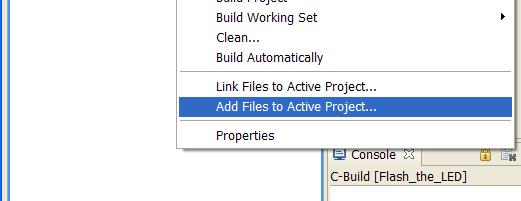
54 Add a File to the CCS Project Right click project and Add Files Navigate to Desktop\MSP430Training\Labs\Lab1 And select Flash_the_LED.c 54


55 Build & Debug a CCS Project Click the BUG to build the code & launch the debugger 55


56 CCS Window C/C++ Perspective Overview 1-click project Debug Independent Debug and C/C++ Project Perspectives Project View List of all Projects Project Outline Shortcut to project parts Console Build Information Code Window Real-time breakpoints, Syntax highlighting Problems View Information, Warnings, Errors 56


57 CCS Window Debug Perspective Overview 1-click project Debug Independent Debug and C/C++ Project Perspectives Target control Start Stop Halt Stepping Stack Trace Highly configurable window layout User preferences Plugin support Real-time, in-system MSP430 information Register access Flash, RAM, Info segment access Disassembly view Program Size Info Code Window Real-time breakpoints, Syntax highlighting 57
58 Is the LED blinking?
59 Lab 1 Check List Open, Use and Explore CCS Play with lab hardware MSP430EXPFG4618 Use the programmer MSP-FET430UIF Establish communication with the MSP430 device Blink an LED 15 mins
60 Lab2A: Using polled flags to determine an interrupt event 60
61 Lab2A Goals Create a new CCS project titled LAB2A (same as LAB1) Lab2A: Using polled flags to determine an interrupt event Use source code lab2_poll.c Configure switch S1 (P1.0) to accept an interrupt Poll P1IFG.0 to determine if a switch press has occurred Toggle LED4 (P5.1) on switch press Measure power when JP3 (near LED4) is open
62 Create a CCS Project File > New > CCS Project Project Name: LAB2A Project Type: MSP430 Additional Project Settings: <None> 62

63 Add a File to the CCS Project Right click project and Add Files Navigate to Desktop\MSP430Training\Labs\Lab2 And select lab2_poll.c 63
64 Complete the Source Code Setup P1.0 for an interrupt on a HI/LOW transition Test P1IFG.BIT0 flag for event Toggle P5.1 Source file : lab2_poll.c
65 Complete the Source Code Setup P1.0 for an interrupt on a HI/LOW transition Test P1IFG.BIT0 flag for event Toggle P5.1 Source file : lab2_poll_solution.c

66 Build & Debug a CCS Project Click the BUG to build the code & launch the debugger 66

67 Current measurement JP3 A LED ON(mA) LED OFF(mA) BATT JP ~0 Current consumed by device when polling A BATT
68 Wrap-Up 2/16/
69 Wrap-Up Discussed the digital IO Interrupt processing in MSP430 MSP430 tool chain Programming MSP430 using Code Composer Studio (CCS) 2/16/
70 References Train the Trainer, courseware prepared by Priya Thanigai, Ramakrishna Reddy K, Texas Instruments, February 2011 MSP430 Microcontroller Basics, John H.Davies, Newnes, 2010 MSP430 Teaching ROM, Pedro Dinis Gaspar, Antnio Esprito Santo, Bruno Ribeiro and Humberto Santos University of Beira Interior, Electromechanical Engineering Department, Portugal, 2009 The 8051 Microcontroller and Embedded Systems Using Assembly and C, Muhammad Ali Mazidi, Janice Gillispie Mazidi, Rolin D.McKinlay, Pearson 2/16/
71 2/16/
72 Program counter bit-0 is always tied to 0
73 Status register - does not have the Parity bit in MSP430


74 What happens upon a call instruction(1)


75 What happens upon a call instruction(2)
")
76 What happens upon a call instruction(3)
77 Types of non-volatile memory ROM EPROM OTP (One-Time Programmable) Flash NOR flash: slower to write but permits random access e.g., Most microcontrollers for fixed applications NAND flash: Used in bulk storage devices and can be accessed only serially in rows e.g., USB memory stick
78 Crystal accuracy and ppm Refer to the Faculty development document. Note : Apologies I do not recall the source of this
Lab 4: Interrupt. CS4101 Introduction to Embedded Systems. Prof. Chung-Ta King. Department of Computer Science National Tsing Hua University, Taiwan
 CS4101 Introduction to Embedded Systems Lab 4: Interrupt Prof. Chung-Ta King Department of Computer Science, Taiwan Introduction In this lab, we will learn interrupts of MSP430 Handling interrupts in MSP430
Interrupts CS4101 嵌入式系統概論. Prof. Chung-Ta King. Department of Computer Science National Tsing Hua University, Taiwan
 CS4101 嵌入式系統概論 Interrupts Prof. Chung-Ta King Department of Computer Science, Taiwan Materials from MSP430 Microcontroller Basics, John H. Davies, Newnes, 2008 Inside MSP430 (MSP430G2551) 1 Introduction
Create and Add the Source File
 IAR Kickstart Procedure Create and Add the Source File 8. Create the Source File From the IAR Embedded Workbench menu bar, select File New File. In the untitled editor window that appears, type the following
Lecture 2 MSP430 Architecture. Atul Lele Ramakrishna Reddy
 Lecture 2 MSP430 Architecture Atul Lele Ramakrishna Reddy About me Education B.E. in Electronics and Telecommunication, PICT, Pune (2000) Professional experience Working with Texas Instruments India Pvt
Block diagram of processor (Harvard)
") Block diagram of processor (Harvard) Register transfer view of Harvard architecture Separate busses for instruction memory and data memory Example: PIC 16 load path OP REG AC 16 16 store path rd wr data
Block diagram of processor (Harvard) Register transfer view of Harvard architecture Separate busses for instruction memory and data memory Example: PIC 16 load path OP REG AC 16 16 store path rd wr data
Designing for Ultra-Low Power with MSP430
 Designing for Ultra-Low Power with MSP430 Christian Hernitscheck MSP430 FAE Europe Texas Instruments 2006 Texas Instruments Inc, Slide 1 Agenda Introduction to Ultra-Low Power Looking for Ultra-Low Power
MSP430. More on MSP430
 MSP430 More on MSP430 CodeComposer TI recently launched Code Composer Essentials v3. This IDE s latest version (version 3) supports all available MSP430 devices. The new features of CCE v3 include: - Free
6. General purpose Input/Output
 Chapter 6 6. General purpose Input/Output This chapter starts with a description of one of the simplest integrated peripherals of the MSP430 the General Purpose 8-bit Input Output (GPIO). The Input/Output
IV B.Tech. I Sem (R13) ECE : Embedded Systems : UNIT -2 1 UNIT 2
 ECE : Embedded Systems : UNIT -2 1 UNIT 2") IV B.Tech. I Sem (R13) ECE : Embedded Systems : UNIT -2 1 UNIT 2 1. Block diagram of MSP430x5xx series micro-controller --------------------- 1 2. CPU architecture of MSP430x5xx ------------------------------------------------
IV B.Tech. I Sem (R13) ECE : Embedded Systems : UNIT -2 1 UNIT 2 1. Block diagram of MSP430x5xx series micro-controller --------------------- 1 2. CPU architecture of MSP430x5xx ------------------------------------------------
Lecture 5: MSP430 Interrupt
 ECE342 Intro. to Embedded Systems Lecture 5: MSP430 Interrupt Ying Tang Electrical and Computer Engineering Rowan University 1 How A Computer React to Inputs? Polling: the processor regularly looks at
Lab 4 Interrupts ReadMeFirst
 Lab 4 Interrupts ReadMeFirst Lab Folder Content 1) ReadMeFirst 2) Interrupt Vector Table 3) Pin out Summary Objectives Understand how interrupts work Learn to program Interrupt Service Routines in C Language
CPE 323: MSP430 Timers
 CPE 323: MSP430 Timers Aleksandar Milenkovic Electrical and Computer Engineering The University of Alabama in Huntsville milenka@ece.uah.edu http://www.ece.uah.edu/~milenka Outline Watchdog Timer TimerA
Lecture test next week
 Lecture test next week Write a short program in Assembler doing. You will be given the print outs of all the assembler programs from the manual You can bring any notes you want Today: Announcements General
CPE 323 Introduction to Embedded Computer Systems: MSP430 System Architecture An Overview
 CPE 323 Introduction to Embedded Computer Systems: MSP430 System Architecture An Overview Aleksandar Milenkovic Electrical and Computer Engineering The University of Alabama in Huntsville milenka@ece.uah.edu
Today's plan: Announcements General Strategy Microcontroller programming concepts/last bits of assembly Activity 2
 Today's plan: Announcements General Strategy Microcontroller programming concepts/last bits of assembly Activity 2 Intro to programming in C time permitting Lab 1&2 Marking scheme: Announcements: Turn
Microcontrollers. vs Microprocessors
 Microcontrollers vs Microprocessors Microprocessors Arbitrary computations Arbitrary control structures Arbitrary data structures Specify function at high-level and use compilers and debuggers Composed
Alex Milenkovich 1. CPE/EE 421 Microcomputers: The MSP430 Introduction. Outline
 Outline CPE/EE 421 Microcomputers: The MSP430 Introduction Instructor: Dr Aleksandar Milenkovic Lecture Notes MSP430: An Introduction The MSP430 family Technology Roadmap Typical Applications The MSP430
Lab 1: I/O, timers, interrupts on the ez430-rf2500
 Lab 1: I/O, timers, interrupts on the ez430-rf2500 UC Berkeley - EE 290Q Thomas Watteyne January 25, 2010 1 The ez430-rf2500 and its Components 1.1 Crash Course on the MSP430f2274 The heart of this platform
Texas Instruments Mixed Signal Processor Tutorial Abstract
 Texas Instruments Mixed Signal Processor Tutorial Abstract This tutorial goes through the process of writing a program that uses buttons to manipulate LEDs. One LED will be hard connected to the output
CPE 325: Embedded Systems Laboratory Laboratory #7 Tutorial MSP430 Timers, Watchdog Timer, Timers A and B
 CPE 325: Embedded Systems Laboratory Laboratory #7 Tutorial MSP430 Timers, Watchdog Timer, Timers A and B Aleksandar Milenković Email: milenka@uah.edu Web: http://www.ece.uah.edu/~milenka Objective This
2006 Mixed Signal Products SLAU049F
 User s Guide 2006 Mixed Signal Products SLAU049F Related Documentation From Texas Instruments Preface About This Manual This manual discusses modules and peripherals of the MSP430x1xx family of devices.
What is an Interrupt?
 MSP430 Interrupts What is an Interrupt? Reaction to something in I/O (human, comm link) Usually asynchronous to processor activities interrupt handler or interrupt service routine (ISR) invoked to take
2006 Mixed Signal Products SLAU144B
 User s Guide 2006 Mixed Signal Products SLAU144B IMPORTANT NOTICE Texas Instruments Incorporated and its subsidiaries (TI) reserve the right to make corrections, modifications, enhancements, improvements,
2006 Mixed Signal Products SLAU049F
 User s Guide 2006 Mixed Signal Products SLAU049F IMPORTANT NOTICE Texas Instruments Incorporated and its subsidiaries (TI) reserve the right to make corrections, modifications, enhancements, improvements,
Designing for Ultra-Low Power with MSP430
 Designing for Ultra-Low Power with MSP430 Christian Hernitscheck MSP430 FAE Europe Texas Instruments 2006 Texas Instruments Inc, Slide 1 Agenda Introduction to Ultra-Low Power Looking for Ultra-Low Power
ECE2049: Embedded Computing in Engineering Design C Term Spring 2019 Lecture #22: MSP430F5529 Operating Mode & the WDT
 ECE2049: Embedded Computing in Engineering Design C Term Spring 2019 Lecture #22: MSP430F5529 Operating Mode & the WDT Reading for Today: User's Guide 1.4, Ch 16 Reading for Next Class: Review all since
Getting Started with the MSP430 LaunchPad
 Getting Started with the MSP430 LaunchPad Student Guide and Lab Manual Revision 1.0 October 2010 Technical Training Organization Important Notice Important Notice Texas Instruments and its subsidiaries
Wireless Sensor Networks (WSN)
") Wireless Sensor Networks (WSN) Operating Systems M. Schölzel Operating System Tasks Traditional OS Controlling and protecting access to resources (memory, I/O, computing resources) managing their allocation
Wireless Sensor Networks (WSN) Operating Systems M. Schölzel Operating System Tasks Traditional OS Controlling and protecting access to resources (memory, I/O, computing resources) managing their allocation
Interrupts, Low Power Modes
 Interrupts, Low Power Modes Registers Status Register Interrupts (Chapter 6 in text) A computer has 2 basic ways to react to inputs: 1) polling: The processor regularly looks at the input and reacts as
ECGR 4101/5101, Fall 2016: Lab 1 First Embedded Systems Project Learning Objectives:
 ECGR 4101/5101, Fall 2016: Lab 1 First Embedded Systems Project Learning Objectives: This lab will introduce basic embedded systems programming concepts by familiarizing the user with an embedded programming
Interrupt Driven Programming in MSP430 Assembly (ESCAPE) *
 *") OpenStax-CNX module: m45965 1 Interrupt Driven Programming in MSP430 Assembly (ESCAPE) * Matthew Johnson Based on Interrupt Driven Programming in MSP430 Assembly by Matthew Johnson This work is produced
OpenStax-CNX module: m45965 1 Interrupt Driven Programming in MSP430 Assembly (ESCAPE) * Matthew Johnson Based on Interrupt Driven Programming in MSP430 Assembly by Matthew Johnson This work is produced
Copyright 2015 by Stephen A. Zajac & Gregory M. Wierzba. All rights reserved..spring 2015.
 Copyright 2015 by Stephen A. Zajac & Gregory M. Wierzba. All rights reserved..spring 2015. Copyright 2015 by Stephen A. Zajac & Gregory M. Wierzba. All rights reserved..spring 2015. Copyright 2015 by Stephen
5xx Active & Low Power Mode Operation
 5xx Active & Low Power Mode Operation 38 Lab 2: ULP Operation Lab Goals Learn ULP Best Practices Learn & understand how to configure two key modules of the 5xx to achieve ultra-low power operation. Power
Timer Module Timer A. ReadMeFirst
 Timer Module Timer A ReadMeFirst Lab Folder Content 1) ReadMeFirst 2) TimerModule Lecture material 3) PinOutSummary 4) InterruptsVectorTable 5) Source code for screencast Interrupt Review Overview A Timer
The digital I/O is configured with user software. The setup and operation of the digital I/O is discussed in the following sections.
 Digital I/O Introduction www.ti.com 8. Digital I/O Introduction MSP43 devices have up to eight digital I/O ports implemented, P to P8. Each port has up to eight I/O pins. Every I/O pin is individually
MSP430 Interrupts. Change value of internal variable (count) Read a data value (sensor, receive) Write a data value (actuator, send)
 Read a data value (sensor, receive) Write a data value (actuator, send)") MSP430 Interrupts What is an Interrupt? Reaction to something in I/O (human, comm link) Usually asynchronous to processor activities interrupt handler or interrupt service routine (ISR) invoked to take
MSP430 Interrupts What is an Interrupt? Reaction to something in I/O (human, comm link) Usually asynchronous to processor activities interrupt handler or interrupt service routine (ISR) invoked to take
Basic System Memory Architecture View (Functional)
") Memory Organization Basic System Memory Architecture View (Functional) Notation: [FFFE]=27h FFFE: 27 Basic Characteristics (1/3) Memory cell registers are one byte wide Memory Word is the contents of the
Memory Organization Basic System Memory Architecture View (Functional) Notation: [FFFE]=27h FFFE: 27 Basic Characteristics (1/3) Memory cell registers are one byte wide Memory Word is the contents of the
// Conditions for 9600/4=2400 Baud SW UART, SMCLK = 1MHz #define Bitime_5 0x05*4 // ~ 0.5 bit length + small adjustment #define Bitime 13*4//0x0D
 /****************************************************************************** * * * 1. Device starts up in LPM3 + blinking LED to indicate device is alive * + Upon first button press, device transitions
ECE2049: Embedded Computing in Engineering Design C Term Spring Lecture #11: More Clocks and Timers
 ECE2049: Embedded Computing in Engineering Design C Term Spring 2018 Lecture #11: More Clocks and Timers Reading for Today: Davie's Ch 8.3-8.4, 8.9-8.10, User's Guide Ch. 17 Reading for Next Class: User's
MSP430 Teaching Materials
 MSP430 Teaching Materials Lecture 11 Flash Programming & TLV Structure Texas Instruments t Incorporated University of Beira Interior (PT) Pedro Dinis Gaspar, António Espírito Santo, Bruno Ribeiro, Humberto
Timers and Clocks CS4101 嵌入式系統概論. Prof. Chung-Ta King. Department of Computer Science National Tsing Hua University, Taiwan
 CS4101 嵌入式系統概論 Timers and Clocks Prof. Chung-Ta King Department of Computer Science, Taiwan Materials from MSP430 Microcontroller Basics, John H. Davies, Newnes, 2008 Recall the Container Thermometer Container
Before next weeks lab:
 Before next weeks lab: - To sign in to lab computers use student and Phys319. - read the lab manual for week two. - look at the tools installation guide for OS of your choice and/or lab computer guide,
ECE2049 E17 Lecture 4 MSP430 Architecture & Intro to Digital I/O
 ECE2049-E17 Lecture 4 1 ECE2049 E17 Lecture 4 MSP430 Architecture & Intro to Digital I/O Administrivia Homework 1: Due today by 7pm o Either place in box in ECE office or give to me o Office hours tonight!
Getting Started with the MSP430 IAR Assembly
 Getting Started with the MSP430 IAR Assembly by Alex Milenkovich, milenkovic@computer.org Objectives: This tutorial will help you get started with the MSP30 IAR Assembly program development. You will learn
Microcontroller Basics
 Microcontroller Basics Gabe Cohn CSE 599U February 6, 2012 www.gabeacohn.com/teaching/micro Outline Overview of Embedded Systems What is a Microcontroller? Microcontroller Features Common Microcontrollers
Embedded Technosolutions
 MSP430 Tutorial Very Important Low Power Processor For Embedded Systems Applications Introduction Although there are many resources dedicated to teaching microcontrollers and the MSP430 in particular,
2.996/6.971 Biomedical Devices Design Laboratory Lecture 6: Microprocessors II
 2.996/6.971 Biomedical Devices Design Laboratory Lecture 6: Microprocessors II Instructor: Dr. Hong Ma Oct. 1, 2007 Structure of MSP430 Program 1. Declarations 2. main() 1. Watch-dog timer servicing 2.
Team 3. By: Miriel Garcia. Microcontrollers/ TI MSP430F5438A. ECE 480 senior Design. Application Note 4/3/15
 Microcontrollers/ TI MSP430F5438A ECE 480 senior Design Team 3 Application Note By: Miriel Garcia 4/3/15 Abstract Microcontrollers are key components on today s modern world. These devices have the ability
PHYS 319. Things to do before next week's lab Whirlwind tour of the MSP430 CPU and its assembly language Activity 1.
 PHYS 319 Things to do before next week's lab Whirlwind tour of the MSP430 CPU and its assembly language Activity 1. Before next week's lab: Read manual for Lab 2 and your OS setup guide then prepare your
ez430-chronos Wireless Watch Development Tool: Teardown & Getting Started
 ez430-chronos Wireless Watch Development Tool: Teardown & Getting Started www.ti.com/chronoswiki ez430-chronos for wireless networking applications Complete hardware, software and support community Simplify
Physics 319 Spring 2015: Introduction to the Programming and Use of Microprocessors
 Physics 319 Spring 2015: Introduction to the Programming and Use of Microprocessors Sing Chow, Andrzej Kotlicki, Ryan Wicks, and Carl Michal December 2014 This lab is going to introduce you to the world
MSP430x43x1, MSP430x43x, MSP430x44x1, MSP430x44x MIXED SIGNAL MICROCONTROLLER
 Low Supply-Voltage Range,.8 V to 3.6 V Ultralow-Power Consumption: Active Mode: 28 µa at MHz, 2.2 V Standby Mode:. µa Off Mode (RAM Retention):. µa Five Power Saving Modes Wake-Up From Standby Mode in
University of Texas at El Paso Electrical and Computer Engineering Department. EE 3176 Laboratory for Microprocessors I.
 University of Texas at El Paso Electrical and Computer Engineering Department EE 3176 Laboratory for Microprocessors I Fall 2016 LAB 03 Low Power Mode and Port Interrupts Goals: Bonus: Pre Lab Questions:
University of Texas at El Paso Electrical and Computer Engineering Department. EE 3176 Laboratory for Microprocessors I.
 University of Texas at El Paso Electrical and Computer Engineering Department EE 3176 Laboratory for Microprocessors I Fall 2016 LAB 04 Timer Interrupts Goals: Learn about Timer Interrupts. Learn how to
Software Setup and Introductory Assembly programs for the MSP430 *
 OpenStax-CNX module: m15976 1 Software Setup and Introductory Assembly programs for the MSP430 * Texas Instruments This work is produced by OpenStax-CNX and licensed under the Creative Commons Attribution
SKP16C26 Tutorial 1 Software Development Process using HEW. Renesas Technology America Inc.
 SKP16C26 Tutorial 1 Software Development Process using HEW Renesas Technology America Inc. 1 Overview The following tutorial is a brief introduction on how to develop and debug programs using HEW (Highperformance
Getting Started with the MSP430 LaunchPad
 Getting Started with the MSP430 LaunchPad Student Guide and Lab Manual Revision 2.01 February 2012 Technical Training Organization Important Notice Important Notice Texas Instruments and its subsidiaries
Getting Started with the Texas Instruments ez430
 1 of 6 03.01.2009 01:33 HOME Running Your Code>> Getting Started with the Texas Instruments ez430 Working with the Workbench Software Step 1: Each program needs an associated project. The project includes
ECE2049 Homework #2 The MSP430 Architecture & Basic Digital IO (DUE Friday 9/8/17 at 4 pm in class)
") ECE2049 Homework #2 The MSP430 Architecture & Basic Digital IO (DUE Friday 9/8/17 at 4 pm in class) Your homework should be neat and professional looking. You will loose points if your HW is not properly
ECE2049 Homework #2 The MSP430 Architecture & Basic Digital IO (DUE Friday 9/8/17 at 4 pm in class) Your homework should be neat and professional looking. You will loose points if your HW is not properly
Copyright 2009 Texas Instruments All Rights Reserved
 MSP430 Teaching Materials Week 3 Further into the MSP430 Hacettepe University Anatomy of a Typical Small Microcontroller Central processing unit Arithmetic logic unit (ALU), which performs computation.
Network Embedded Systems Sensor Networks Fall Hardware. Marcus Chang,
 Network Embedded Systems Sensor Networks Fall 2013 Hardware Marcus Chang, mchang@cs.jhu.edu 1 Embedded Systems Designed to do one or a few dedicated and/or specific functions Embedded as part of a complete
Intro. MEB/ Texas Instruments Inc, Slide 1
 Intro MEB/0404 2004 Texas Instruments Inc, Slide 1 MSP430 Agenda Core Architecture Integrated Peripherals Device Roadmap Ideal Applications Development Tools MEB/0404 2004 Texas Instruments Inc, Slide
The industrial technology is rapidly moving towards ARM based solutions. Keeping this in mind, we are providing a Embedded ARM Training Suite.
 EMBEDDED ARM TRAINING SUITE ARM SUITE INCLUDES ARM 7 TRAINER KIT COMPILER AND DEBUGGER THROUGH JTAG INTERFACE PROJECT DEVELOPMENT SOLUTION FOR ARM 7 e-linux LAB FOR ARM 9 TRAINING PROGRAM INTRODUCTION
Hacettepe University
 MSP430 Teaching Materials Week 5 FUNDAMENTALS OF INTERFACING AND TIMERS for MSP430 Hacettepe University Elements in Basic MCU Interface Power Source Feeds CPU and peripherals Clock Oscillators System synchronization
Introduction to the Texas Instruments ez430. By: Naren Anand
 Introduction to the Texas Instruments ez430 By: Naren Anand Introduction to the Texas Instruments ez430 By: Naren Anand Online: C O N N E X I O N S Rice University,
Getting Started With the Stellaris EK-LM4F120XL LaunchPad Workshop. Version 1.05
 Getting Started With the Stellaris EK-LM4F120XL LaunchPad Workshop Version 1.05 Agenda Introduction to ARM Cortex Cortex -M4F M4F and Peripherals Code Composer Studio Introduction to StellarisWare, I iti
Hacettepe University
 www.msp430.ubi.pt MSP430 Teaching Materials Introductory Overview Week2 Hacettepe University Outline Microcontrollers Versus Microprocessors Central Processing Unit System Buses Memory Organization I/O
Lab 0 Introduction to the MSP430F5529 Launchpad-based Lab Board and Code Composer Studio
 ECE2049 Embedded Computing in Engineering Design Lab 0 Introduction to the MSP430F5529 Launchpad-based Lab Board and Code Composer Studio In this lab, you will be introduced to the Code Composer Studio
MSP-EXP430fr5994 Experimenter Board with noforth 5994
 (jan 2018) noforth website MSP-EXP430fr5994 Experimenter Board with noforth 5994 1. MSP-EXP430fr5994 Experimenter Board with noforth 5994 i/o port connections on Experimenter Board Connectors on Experimenter
E8a Emulator Additional Document for User's Manual R0E00008AKCE00EP9
 REJ10J1646-0100 E8a Emulator Additional Document for User's Manual R0E00008AKCE00EP9 Renesas Microcomputer Development Environment System M16C Family / R8C/Tiny Series Notes on Connecting the R8C/18, R8C/19,
Interfacing CMA3000-D01 to an MSP430 ultra low-power microcontroller
 Interfacing CMA3000-D01 to an MSP430 ultra low-power microcontroller 1 INTRODUCTION The objective of this document is to show how to set up SPI/I2C communication between VTI Technologies CMA3000-D01 digital
MSP430 Teaching Materials
 MSP430 Teaching Materials Lecture 5 Timers Description of clock signals Texas Instruments Incorporated University of Beira Interior (PT) Pedro Dinis Gaspar, António Espírito Santo, Bruno Ribeiro, Humberto
Hacettepe University
 MSP430 Teaching Materials Week 3 Further into the MSP430 Hacettepe University Anatomy of a Typical Small Microcontroller Central processing unit Arithmetic logic unit (ALU), which performs computation.
IAR PowerPac RTOS for Texas Instruments MSP430 Microcontroller Family
 IAR PowerPac RTOS for Texas Instruments MSP430 Microcontroller Family CPU and compiler specifics COPYRIGHT NOTICE Copyright 2008 IAR Systems. All rights reserved. No part of this document may be reproduced
Programming in the MAXQ environment
 AVAILABLE The in-circuit debugging and program-loading features of the MAXQ2000 microcontroller combine with IAR s Embedded Workbench development environment to provide C or assembly-level application
TEVATRON TECHNOLOGIES PVT. LTD Embedded! Robotics! IoT! VLSI Design! Projects! Technical Consultancy! Education! STEM! Software!
 Summer Training 2016 Advance Embedded Systems Fast track of AVR and detailed working on STM32 ARM Processor with RTOS- Real Time Operating Systems Covering 1. Hands on Topics and Sessions Covered in Summer
MSP430 Microcontroller Basics
 MSP430 Microcontroller Basics John H. Davies AMSTERDAM BOSTON HEIDELBERG LONDON NEW YORK OXFORD PARIS SAN DIEGO SAN FRANCISCO SINGAPORE SYDNEY TOKYO Newnes is an imprint of Elsevier N WPIGS Contents Preface
MSP430 Interface to LMP91000 Code Library
 Application Note 2230 Vishy Viswanathan July 13, 2012 MSP430 Interface to LMP91000 Code 1.0 Abstract The MSP430 is an ideal microcontroller solution for low-cost, low-power precision sensor applications
MSP430 Interface to LMP91000 Code Library
 MSP430 Interface to LMP91000 Code Library 1.0 Abstract The MSP430 is an ideal microcontroller solution for low-cost, low-power precision sensor applications because it consumes very little power. The LMP91000
Analog Peripherals. Introduction. Objectives
 Analog Peripherals Introduction In this section we ll take a look at the MSP430 analog peripherals. It s not possible in this limited amount of time to give you a complete overview of the possible analog
WHICH MICRO? What does MCU needs to do in my system? What are the tasks? Dr. Adriana Becker-Gomez
 1 WHICH MICRO? What does MCU needs to do in my system? What are the tasks? Dr. Adriana Becker-Gomez Email: axbeec@rit.edu Office: 9-3477 2 Specs System design: High level definition (functional specs)
Interconnects, Memory, GPIO
 Interconnects, Memory, GPIO Dr. Francesco Conti f.conti@unibo.it Slide contributions adapted from STMicroelectronics and from Dr. Michele Magno, others Processor vs. MCU Pipeline Harvard architecture Separate
MIDTERM#1. 2-(3pts) What is the difference between Von Neumann & Harvard processor architectures?
 What is the difference between Von Neumann & Harvard processor architectures?") CSE421-Microprocessors & Microcontrollers-Spring 2013 (March 26, 2013) NAME: MIDTERM#1 1- (2pts) What does MSP stand for in MSP430? Why? Mixed Signal Processor. It contains both analog and digital circuitry.
CSE421-Microprocessors & Microcontrollers-Spring 2013 (March 26, 2013) NAME: MIDTERM#1 1- (2pts) What does MSP stand for in MSP430? Why? Mixed Signal Processor. It contains both analog and digital circuitry.
Application Report. 1 Hardware Description. John Fahrenbruch... MSP430 Applications
 Application Report SLAA309 June 2006 Low-Power Tilt Sensor Using the MSP430F2012 John Fahrenbruch... MSP430 Applications ABSTRACT The MSP430 family of low-power microcontrollers are ideal for low-power
ECSE-426. Microprocessor Systems. 2: Assembly + C 1
 ECSE-426 Microprocessor Systems 2: Assembly + C 1 Today s Lecture Theory Tutorial Appendix Multi-level machines Problem-oriented language layer Language Choice Machine Architecture Introduction to the
M16C R8C FoUSB/UART Debugger. User Manual REJ10J
 REJ10J1725-0100 M16C R8C FoUSB/UART Debugger User Manual Renesas Microcomputer Development Environment System R8C Family R8C/2x Series Notes on Connecting R8C/2A, R8C/2B, R8C/2C, R8C/2D Rev.1.00 Issued
Getting Started with STK200 Dragon
 Getting Started with STK200 Dragon Introduction This guide is designed to get you up and running with main software and hardware. As you work through it, there could be lots of details you do not understand,
Moses Jones Application Note ECE 480 Design Team 7 Programming Altimeters. Using MSP 430 Launch Pad 11/8/2013
 Moses Jones Application Note ECE 480 Design Team 7 Programming Altimeters Executive Summary Using MSP 430 Launch Pad 11/8/2013 This document will provide a guide of how to use the MSP 430 Launch Pad while
F28335 ControlCard Lab1
 F28335 ControlCard Lab1 Toggle LED LD2 (GPIO31) and LD3 (GPIO34) 1. Project Dependencies The project expects the following support files: Support files of controlsuite installed in: C:\TI\controlSUITE\device_support\f2833x\v132
Hacettepe University
 MSP430 Teaching Materials Week 5 FUNDAMENTALS OF INTERFACING AND TIMERS for MSP430 Hacettepe University Elements in Basic MCU Interface Power Source Feeds CPU and peripherals Clock Oscillators System synchronization
esi-risc Development Suite Getting Started Guide
 1 Contents 1 Contents 2 2 Overview 3 3 Starting the Integrated Development Environment 4 4 Hello World Tutorial 5 5 Next Steps 8 6 Support 10 Version 2.5 2 of 10 2011 EnSilica Ltd, All Rights Reserved
063[[[0LFURFRQWUROOHUV /RZ3RZHU0RGHV &3($GYDQFHG0LFURFRPSXWHU7HFKQLTXHV 'U(PLO-RYDQRY /RZ3RZHU. Power: A First-Class Architectural Design Constraint
 063[[[0LFURFRQWUROOHUV /RZ3RZHU0RGHV &3($GYDQFHG0LFURFRPSXWHU7HFKQLTXHV 'U(PLO-RYDQRY MSP430 low power concepts 1 /RZ3RZHU Power: A First-Class Architectural Design Constraint Trevor Mudge, IEEE Computer,
E8a Emulator Additional Document for User's Manual R0E00008AKCE00EP2
 REJ10J1644-0100 E8a Emulator Additional Document for User's Manual R0E00008AKCE00EP2 Renesas Microcomputer Development Environment System M16C Family / R8C/Tiny Series Notes on Connecting the R8C/10, R8C/11,
CPE/EE 421 Microcomputers
 CPE/EE 421 Microcomputers Instructor: Dr Aleksandar Milenkovic Lecture Note S09 *Material used is in part developed by Dr. D. Raskovic and Dr. E. Jovanov CPE/EE 421/521 Microcomputers 1 Performance Outline
IAR EWARM Quick Start for. Holtek s HT32 Series Microcontrollers
 IAR EWARM Quick Start for Holtek s Microcontrollers Revision: V1.10 Date: August 25, 2011 Table of Contents 1 Introduction... 5 About the Quick Start Guide... 5 About the IAR EWARM... 6 2 System Requirements...
CONTENTS: Program 1 in C:
 CONTENTS: 1) Program 1 in C (Blink) 2) Program 2 in C (Interrupt ) 3) ADC example 4) Addressing Modes 5) Selected Assembly instructions 6) ADC10 register descriptions Program 1 in C: /* * PHYS319 Lab3
MetaWatch Firmware Design Guide
 MetaWatch Firmware Design Guide MetaWatch Firmware Design Guide Page 1 of 14 1 Contents 1 Contents... 2 2 Introduction... 3 2.1 Revision History... 4 3 Hardware... 5 3.1 Common Watch Features... 5 3.2
embos Real Time Operating System CPU & Compiler specifics for Texas Instruments MSP430 CPUs and Rowley compiler for MSP430 Document Rev.
 embos Real Time Operating System CPU & Compiler specifics for Texas Instruments MSP430 CPUs and Rowley compiler for MSP430 Document Rev. 1 A product of Segger Microcontroller Systeme GmbH www.segger.com
April 4, 2001: Debugging Your C24x DSP Design Using Code Composer Studio Real-Time Monitor
 1 This presentation was part of TI s Monthly TMS320 DSP Technology Webcast Series April 4, 2001: Debugging Your C24x DSP Design Using Code Composer Studio Real-Time Monitor To view this 1-hour 1 webcast
ECE PRACTICE EXAM #2 Clocks, Timers, and Digital I/O
 ECE2049 -- PRACTICE EXAM #2 Clocks, Timers, and Digital I/O Study HW3, Class Notes, Davies Ch 2.6, 5.8, 8, 9.2-3, 9.7, MSP43F5529 User's Guide Ch 5, 17, 28 Work all problems with your note sheet first