MICROCONTROLLER LAB Version 1.0 Aug 2017
|
|
|
- Debra Warren
- 6 years ago
- Views:
Transcription


1 1 Channabasaveshwara Institute of Technology (An ISO 9001:2015 Certified Institution) NH 206 (B.H. Road), Gubbi, Tumkur Karnataka. Department of Electrical & Electronics Engineering MICROCONTROLLER LAB Version 1.0 Aug 2017 Prepared by: Mrs. Radha B.N. Assistant Professor Reviewed by: Mr. Lokanathan M.S. Assistant Professor Mr.Praveen M.G. Assistant Professor Mr.Santhosh S Assistant Professor Ms. Tejeswini M.V. Assistant Professor Approved by: Prof. V C Kumar Professor & Head,
2 2 INTRODUCTION MCS 8051 is an 8-bit single chip microcontroller with many built-in functions and is the core for all MCS-51 devices. The main features of the 8051 core are: Operates with single Power Supply +5V. 8-bit CPU optimized for control applications. 16-bit program counter (PC) and 16-bit data pointer (DPTR). 8-bit program status word (PSW). 8-bit stack pointer (SP). 4K Bytes of On-Chip Program Memory (Internal ROM or EPROM). 128 bytes of On-Chip Data Memory (Internal RAM): o Four Register Banks, each containing 8 registers (R0 to R7) (Total 32 registers). o 16 bytes of bit addressable memory. o 80 bytes of general-purpose data memory (Scratch Pad Area). Special Function Registers (SFR) to configure/operate microcontroller. 32 bit bi-directional I/O Lines (4 ports P0 to P3). Two 16-bit timers/counters (T0 and T1). Full duplex UART (Universal Asynchronous Receiver/Transmitter). 6-source/5-vector interrupts (2 external and 3 internal) with two priority levels. On-Chip oscillator and clock circuitry. Figure below shows the general block diagram EXTERNAL INTERRUPTS INTERRUPT CONTROL 4 K ROM 128 Byte RAM TIMER 1 TIMER 0 COUNTER INPUTS CPU OSC BUS CONTROL 4 I/O PORTS SERIAL CONTROL P0 P2 P1 P3 TXD RXD ADDRESS / DATA General Block Diagram of 8051 Microcontroller Architecture
3 3 Special Function Registers: 1. Timer Mode Control Register (TMOD): TMOD can be considered to be two duplicate 4-bit registers, each of which controls the action of one of the timers. The Timer or Counter function is selected by control bits C/T, and in different operating modes, which are selected by bit-pairs (M1, M0) in TMOD. MSB LSB GATE C / T M1 M0 GATE C / T M1 M0 GATE C/T M1 M Timer 1 Timer 0 Gating control when set. Counter x is enabled only while INTx pin is high and TRx control pin is set. When cleared Timer x is enabled whenever TRx control bit is set. Timer or Counter Selector cleared for Timer operation (input from internal system clock.) Set for Counter operation (input from Tx input pin). OPERATI0N 13-bit Timer/Counter 5-bits of TLx and 8-bits of THx are used. 16-bit Timer/Counter 8-bits of TLx and 8-bits of THx are cascaded. 8-bit auto-reload Timer/Counter THx holds a value which is to be reloaded into TLx each time it overflows. (Timer 0) TL0 is an 8-bit Timer/Counter controlled by the standard Timer 0 control bits. TH0 is an 8-bit timer only controlled by Timer 1 control bits. Timer/Counter 1 stopped. 2. Timer Control Register (TCON): TCON has control bits and flags for the timers in the upper nibble, and control bits and flags for the external interrupts in lower nibble. MSB LSB TF1 TR1 TF0 TR0 IE1 IT1 IE0 IT0 Bit Symbol Function TCON.7 TF1 Timer 1 overflow flag. Set by hardware on Timer/Counter overflow. Cleared by hardware when processor vectors to interrupt routine, or clearing the bit in software. TCON.6 TR1 Timer 1 Run control bit. Set/cleared by software to turn Timer/Counter on/off. TCON.5 TF0 Timer 0 overflow flag. Set by hardware on Timer/Counter overflow. Cleared by hardware when processor vectors to interrupt routine, or by clearing the bit in software. TCON.4 TR0 Timer 0 Run control bit. Set/cleared by software to turn Timer/Counter on/off. TCON.3 IE1 Interrupt 1 Edge flag. Set by hardware when external interrupts
4 4 edge detected. Cleared when interrupt processed. TCON.2 IT1 Interrupt 1 type control bit. Set/cleared by software to specify falling edge/low level triggered external interrupts. TCON.1 IE0 Interrupt 0 Edge flag. Set by hardware when external interrupts edge detected. Cleared when interrupt processed. TCON.0 IT0 Interrupt 0 Type control bit. Set/cleared by software to specify falling edge/low Level triggered external interrupts. the serial data network. 3.Interrupt Enable (IE) Register : Bit 7 Bit 6 Bit 5 Bit 4 Bit 3 Bit 2 Bit 1 Bit 0 EA x x ES ET1 EX1 ET0 EX0 Symbol Name and Function EA x x - ES ET1 EX1 ET0 EX0 Enable All. If 0, Disables all interrupts and no interrupt is acknowledged. If 1, each interrupt can be individually enabled or disabled by programming appropriate bit. Reserved Enable Serial Interrupt. If 1, enables TI or RI to generate interrupt. Enable Timer 1 interrupt. If 1, Enables the TF1 to generate the interrupt. Enable External interrupt 1. If 1, Enables the INT1 to generate the interrupt. Enable Timer 0 interrupt. If 1, Enables the TF0 to generate the interrupt. Enable External interrupt 0. If 1, Enables the INT0 to generate the interrupt. 4. Interrupt Priority (IP) Register : Each source of the interrupt can be individually programmed to be in either of the two priority levels. The priorities can be assigned to each interrupt by programming appropriate bits in the SFR Interrupt Priority Register. Bit 7 Bit 6 Bit 5 Bit 4 Bit 3 Bit 2 Bit 1 Bit 0 x x x PS PT1 PX1 PT0 PX0 Symbol Name and Function x Reserved x Reserved x - PS Priority of Serial Interrupt. If 1, Priority of Serial Interrupt is higher.
5 5 PT1 PX1 PT0 PX0 Priority of Timer 1 interrupt. If 1, Priority of Timer 1 interrupt is higher. Priority of External interrupt 1. If 1, Priority of the INT1 is higher. Priority of Timer 0 interrupt. If 1, Priority of Timer 0 Interrupt is higher. Priority of External interrupt 0. If 1, Priority of the INT0 is higher. 5. Serial Port Control Register (SCON): The serial port control and status register is the Special Function Register SCON. This register contains not only the mode selection bits, but also the 9th data bit for transmit and receive (TB8 and RB8) and the serial port interrupt bits (TI and RI). MSB LSB SM0 SM1 SM2 REN TB8 RB8 TI RI Where SM0, SM1 specify the serial port mode, as follows: SM0 SM1 Mode Description Baud Rate shift register f osc / bit UART Variable bit UART f osc / 64 or fosc / bit UART variable SM2 REN TB8 RB8 TI RI Enables the multiprocessor communication feature in Modes 2 and 3. In Mode 2 or 3, if SM2 is set to 1, then Rl will not be activated if the received 9th data bit (RB8) is 0. In Mode 1, if SM2=1 then RI will not be activated if a valid stop bit was not received. In Mode 0, SM2 should be 0. Enables serial reception. Set by software to enable reception. Clear by software to disable reception. The 9th data bit that will be transmitted in Modes 2 and 3. Set or clear by software as desired. In Modes 2 and 3, is the 9th data bit that was received. In Mode 1, it SM2=0, RB8 is the stop bit that was received. In Mode 0, RB8 is not used. Transmit interrupt flag. Set by hardware at the end of the 8th bit time in Mode 0, or at the beginning of the stop bit in the other modes, in any serial transmission. Must be cleared by software only. Receive interrupt flag. Set by hardware at the end of the 8th bit time in Mode 0, or halfway through the stop bit time in the other modes, in any serial reception (except see SM2). Must be cleared by software only.

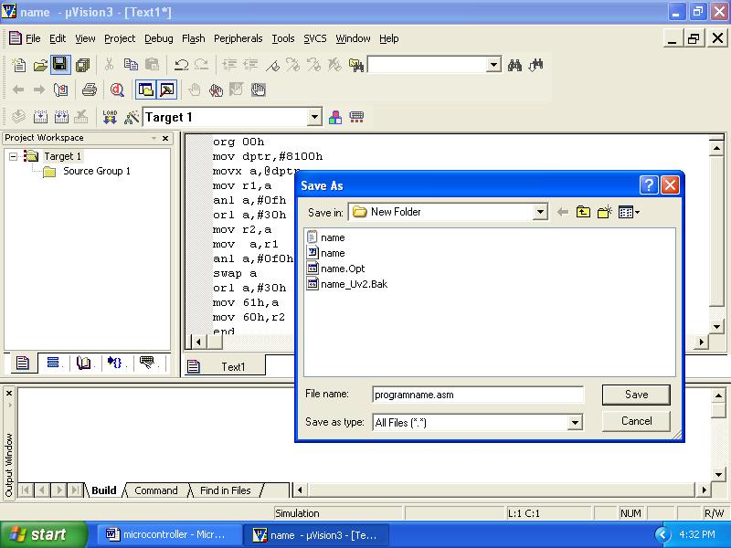
, type in the assembly or C program and save this (filename.")
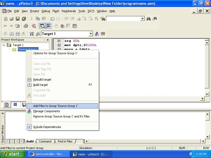
 Project->Manage->Components, Environment Books->addfiles-> browse to the required file -> OK OR ii) right click on the Source Group in the Project Window and the")
 frequency as 11.0592 MHz, and also the Options for Target Debug use either Simulator / Keil Monitor- 51 driver. 6.")
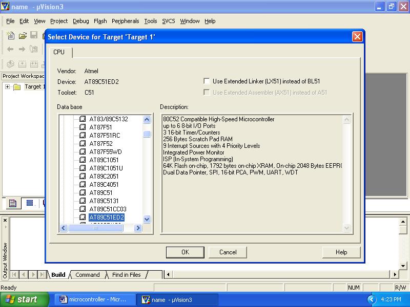
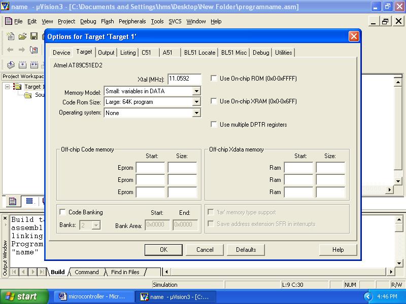
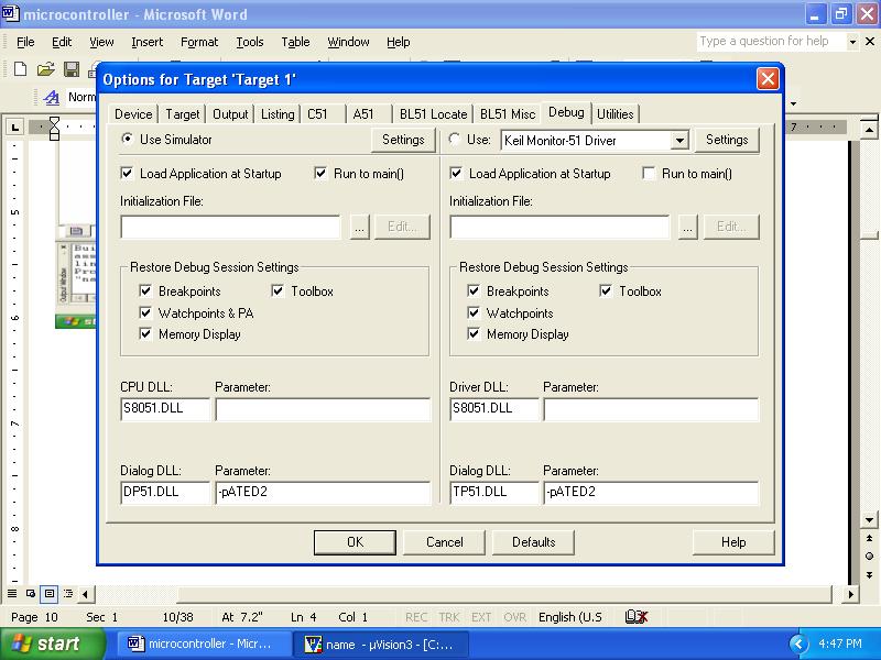
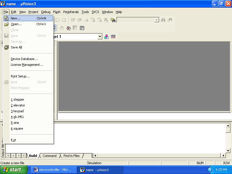
6 6 STEPS TO CREATE AND COMPILE Keil µvision-3/4 PROJECT: 1. Double Click on the icon on the desktop. 2. Close any previous projects that were opened using Project -> Close. 3. Start Project New Project, and select the CPU from the device database (Database-Atmel- AT89C51ED2 or AT89C51RD2 as per the board).on clicking OK, the following option is displayed. Choose No. 4. Create a source file (using File->New), type in the assembly or C program and save this (filename.asm/filename.c) and add this source file to the project using either one of the following two methods. (i) Project->Manage->Components, Environment Books->addfiles-> browse to the required file -> OK OR ii) right click on the Source Group in the Project Window and the Add Files to Group option. 5. Set the Target options using -> Project Options for Target opens the µ Options for Target Target configuration dialog. Set the Xtal (Crystal frequency) frequency as MHz, and also the Options for Target Debug use either Simulator / Keil Monitor- 51 driver. 6. If Keil Monitor- 51 driver is used click on Settings -> COM Port settings select the COM Port to which the board is connected and select the baud rate as or 9600 (recommended). Enable Serial Interrupt option if the user application is not using on-chip UART, to stop program execution.

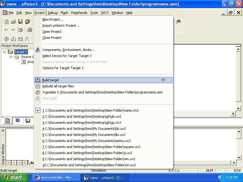
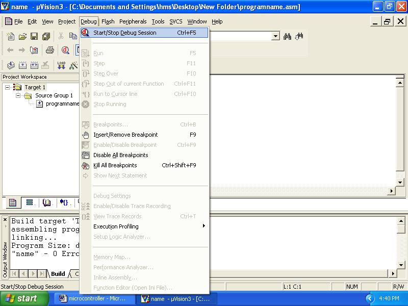
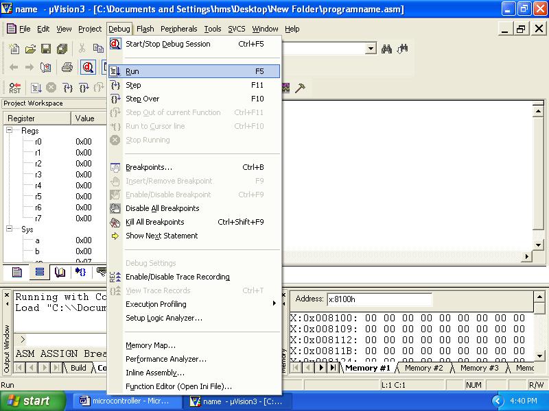
7 7 7. Build the project; using Project -> Build Project. application and links. Any errors in the code are indicated by Target not created in the Build window, along with the error line. Debug the errors. After an error free, to build go to Debug mode. 8. Now user can enter into Debug mode with Debug- Start / Stop Debug session dialog. Or by clicking in the icon. 9. The program is run using the Debug-Run command & halted using Debug-Stop Running. Also the (reset, run, halt) icons can be used. Additional icons are (step, step over, and step into, run till cursor). 10. If it is an interface program the outputs can be seen on the LCD, CRO, motor, led status, etc. If it is a part-a program, the appropriate memory window is opened using View -> memory window (for data RAM & XRAM locations), Watch window (for timer program), serial window, etc. Note: To access data RAM area type address as D: 0020h. Similarly to access the DPTR region (XRAM-present on chip in AT89C51ED2) say 9000h location type in X: 09000H.


8 8 EXECUTION STEPS using KEIL µ vision:
9 9
10 10
11 11
12 12
13 13
14 14 Programming Using 8051 Basic Programs Example 1: Program for addition of two 8 bit no's mov r0,#82h ; move 10h to r0 reg mov a, r0 ; move content r0 reg to accumalator mov r1,#02h ; move 02h to r1 reg mov b,r1 ; move the content of r1 reg to register b add a,b ; add acc with reg b and stores Output in accumalator mov 60h,a ; store Output in the data address (say 60h) end Output: D:60h=12 Example 2: Program for addition of two 16 bit no's Clr c mov r0,#11h mov a,r0 mov r1,#11h add a, r1 mov 21h, a mov r5,#44h mov a, r5 mov r6,#55h addc a, r6 mov 22h,c mov 20h, a end ; clear carry ; get first lower bit no in r0 ; copy ro to accumulator ; get second lower bit no in r1 ; add these two no. ; store the Output ; get first higher bit no in r5 ; copy first higher byte no to accumulator ; Get the second higher byte data in r6 ; add with carry ; Store carry in 22h data location ; store the Output in data location 22h output: r5 r r6 r
15 15 Example 3: Program for swap function (inter changing the nibbles) mov a,#21h mov 30h,a swap a mov 31h,a end ; interchanging lower nibble to higher Output: Initially acc=21 After execution acc=12 Example 4: Program for rotate operations mov a,#21h clr c mov b,a rl a ; rotate accumulator by left mov 30h,a mov a,b rlc a ; rotate accumulator by left through carry mov 31h,a mov a,b rr a ; rotate accumulator by right mov 32h,a mov a,b rrc a ; rotate accumulator by right through carry mov 33h,a end Output: Initially acc=21h rl (d:30h)=42h rlc(d:31h)=42h rr(d:32h)=90h rrc(d:33h)=10h
16 16 Example 5: Program for subtraction of two 8 bit no's Mov r0,#12h ; get first no in ro Mov a,ro ; copy to accumulator Mov r1,#08h ; get second no Subb a, r6 ; subtract accumulator with register r6 Mov 20h, a ; store the Output end Output: acc=12h r6 =08h D:20h= 04h Example 6: Program for subtraction of two 16 bit no's Clr c mov r0,#11h mov a,r0 mov r1,#11h subb a, r1 mov 21h, a mov r5,#44h mov a, r5 mov r6,#55h subb a, r6 mov 20h, a end ; clear carry ; get first lower bit no in r0 ; copy r0 to accumulator ; get second lower bit no in r1 ; subtract these two no ; store the Output ; get first higher bit no in r5 ; copy first higher byte no to accumulator ; Get the second higher byte data in r6 ; subtract with barrow ; store the Output in data location 22h output: r5 r0-44 1A - r6 r
17 17 Example 7: Program to divide two 8-bit no s Mov r0,#12h Mov a,r0 Mov r1,#05h Mov b,r1 Div ab Mov 60h,a Mov 61h,b ; get first no in r0 ; copy r0 value to accumulator ; get second no in r1 ; copy r0 value to register b ; divide A by B ; Quotient value stored in 60h data location ; reminder value to 61h data location Output: D:60h=03 D:61h=03 Example 8: program to multiply two 8-bit no s Mov r0,#12h Mov a,r0 Mov r1,#05h Mov b,r1 Mul ab Mov 60h,a ; get first no in r0 ; copy r0 value to accumulator ; get second no in r1 ; copy r0 value to register b ; multiply A by B ; Output stored in 60h data location Output: D:60h=5A
18 18 Example 9: Program AND, SWAP, OR operations Mov r0,#12h Mov a,r0 Anl a, #0F0h Mov 60h,a Mov a,r0 Swap a Mov 61h,a Mov a,r0 Orl a, 0f0h Mov 62h,a End ; get first no in r0 ; copy r0 value to accumulator ; mask lower bit ; store Output of AND operation in 60h data location ; copy r0 value to accumulator ; exchange upper and lower nibbles of acc ;store Output of AND operation in 61h data location ; copy r0 value to accumulator ; OR operation ;store Output of OR operation in 62h data location Output: D:60h=10 D:61h=21 D:62h=12
19 19
20 20 1(a). Block transfer of data without overlap mov dptr,#9000h mov 30h,#00h mov 31h,#91h mov r7,#05h back: movx inc dptr mov 32h,dpl mov 33h,dph mov dpl,30h mov dph,31h inc dptr mov 30h,dpl mov 31h,dph mov dpl,32h mov dph,33h Output: Before execution Source Memory Location Source Data Destination Memory location Destination data After execution Source Memory Location Source Data Destination Memory location Destination data Output: djnz r7,back end Source Memory Location Source Data Destination Memory location Destination data Source Memory Location Source Data Destination Memory location Destination data Before execution After execution
21 21 Date: 1. Data transfer Program for block data movement, sorting, exchanging, finding largest element in an array. a) Block transfer of data without overlap b) Sorting of data c) Block exchange of data d) Finding largest number in the array Procedure: Double click Kiel μvision Go to project Select Create New project Select Atmel AT89C51ED2 IDE from the Kiel μvision Select New file, Enter the program and Save as (. asm in Assembly and.c in C ) and Click ok Add above file to the project created, build target, debug and run the program observe the result, by giving particular input before execution. Signature of Staff
22 22 1(b) Sorting (Ascending and descending order) mov r0,#04h dec r0 back3: mov r1,00h mov dptr,#9000h back1: movx mov 7fh,a Inc dptr movx cjne a,7fh,exc sjmp back2 exc: jnc back2 mov r3,7fh xch a,r3 dec dpl mov a,r3 inc dptr back2: djnz r1,back1 djnz r0,back3 sjmp $ end Output: for ascending order Before execution Memory Location Data After execution Memory Location Data Memory Location Data Memory Location Data Before execution After execution Output: for Descending order Before execution Memory Location Data After execution Memory Location Data Memory Location Data Memory Location Data Before execution After execution Note: Change the instruction jnc back2 in the program to sort the data in ascending order to jc back2 to sort the data in descending order. Signature of Staff
23 23 1(c) Block exchange of data mov dptr,#9000h mov 30h,#00h mov 31h,#91h mov r7,#05h back: movx mov 32h,dpl mov 33h,dph mov r4,a mov dpl,30h mov dph,31h movx xch a,r4 inc dptr mov 30h,dpl mov 31h,dph mov dpl,32h mov dph,33h mov a,r4 inc dptr djnz r7,back end Output: Date: Before execution Source Memory Location Source Data Destination Memory location Destination data After execution Source Memory Location Source Data Destination Memory location Destination data Source Memory Location Source Data Destination Memory location Destination data Source Memory Location Source Data Destination Memory location Destination data Before execution After execution Signature of Staff
24 24 1(d) Finding the Largest number in a given array: mov dptr,#9000h mov r0,#04h dec r0 movx a,@dptr mov 7fh,a back2: inc dptr movx a,@dptr cjne a,7fh,back1 sjmp back3 back1: jc back3 mov 7fh,a back3: djnz r0,back2 mov 77h,7fh end Output: Before execution Memory Location Data After execution Data Location D:77h 08 Memory Location Data Data Location D:88h Before execution After execution For finding the Smallest element in a given array: Note: Change the instruction jc back3 in the program to find largest element in the Output: array to jnc back3 to find the smallest element in the array. Before execution Memory Location Data After execution Data Location D:77h 01 Memory Location Data Data Location D:88h Before execution After execution Signature of Staff
25 25 2 (a) Addition of two 16 bit numbers: mov dptr,#9001h mov r0,#0ffh mov r1,#0ffh mov r2,#0ffh mov r3,#0ffh clr c mov a,r0 add a,r2 dec dpl mov a,r1 addc a,r3 mov 00h,c sjmp $ end Output: r1 r0 + r3 r
26 26 2. Arithmetic instructions: Addition, subtraction, multiplication and division. Square and cube operations for 16 bit numbers. 2(a) Addition 2(b) Subtraction 2(c ) Multiplication 2(d) Division 2(e) Square of a number 2(f) Cube of a number Procedure: Double click Kiel μvision Go to project Select Create New project Select Atmel AT89C51ED2 IDE from the Kiel μvision Select New file, Enter the program and Save as (. asm in Assembly and.c in C ) and Click ok Add above file to the project created, build target, debug and run the program observe the result, by giving particular input before execution.
27 27 2(b). Program for Subtraction of two 16 bit numbers: mov dptr,#9001h // 5673-fc22 mov r0,#73h mov r1,#56h mov r2,#22h mov r3,#0fch clr c mov a,r0 subb a,r2 dec dpl mov a,r1 subb a,r3 mov 00h,c end Output: r1 r0 - r3 r Signature of Staff
28 28 2(c ) Multiplication of two 16 bit numbers: mov dptr,#9003h mov r0,#23h mov r1,#41h mov r2,#41h mov r3,#32h mov a,r3 mov b,r1 mul ab mov r4,b mov a,r3 mov b,r0 mul ab add a,r4 mov r5,a mov r4,b mov a,r2 mov b,r1 mul ab add a,r5 decd pl mov a,b addc a,r4 mov r4,a mov a,r2 mov b,r0 mul ab add a,r4 dec dpl dec dpl mov a,b end Output: r0 r1 X r2 r
29 29 2 (d) Division of 16 bit by 8 bit number: org 00h mov r0,40h mov r1,41h mov b,43h mov a,r0 div ab mov 45h,a mov a,b mov b,#0ah mul ab add a,r1 mov b,43h div ab mov 46h,a here: sjmp here end Output: r1 r0 b 2 (e) Find square of a number: mov dptr,#9000h movx a,@dptr mov b,a mul ab mov r0,a mov dptr,#900eh mov a,b inc dpl mov a,r0 end Output: X :900eh =(accumulator) 2
30 30 2(f). Program to find cube of a number: mov dptr,#9000h movx a,@dptr mov r0,a mov b,a mul ab mov r1,b mov b,r0 mul ab mov dptr,#900eh mov r2,b mov a,r1 mov b,r0 mul ab add a,r2 dec dpl dec dpl mov a,b end Output: X :900eh =(accumulator) 3 Signature of Staff
31 31 3(a) Program for Binary up counter mov dptr,#9000h next: here: mov a,#00h acall delay inc jnz delay: mov loop1: mov loop2: mov loop3: djnz a next sjmp here r1,#0ffh r2,#0ffh r3,#0ffh r3,loop3 djnz r2,loop2 djnz r1,loop1 ret end Output: x:9000h=00,01,02...ff 3( b). Program for Binary down counter mov dptr,#9000h mov a,#0ffh next: acall dec jnz here: sjmp delay a next a here delay: mov r1,#0ffh loop1: mov r2,#0ffh loop2: mov r3,#0ffh loop3: djnz r3,loop3 djnz r2,loop2 djnz r1,loop1 ret end Output: x:9000h=ff,fe,fd...00 Signature of Staff
32 32 3. Counters : Date: Procedure: Double click Kiel μvision Go to project Select Create New project Select Atmel AT89C51ED2 IDE from the Kiel μvision Select New file, Enter the program and Save as (. asm in Assembly and.c in C ) and Click ok Add above file to the project created, build target, debug and run the program observe the result, by giving particular input before execution.
33 33 3(c). Program for Decimal up counter next: mov dptr,#9000h mov a,#00h acall delay add a,#01h da a jnz next here: sjmp here delay: mov r1,#0ffh loop1: mov r2,#0ffh loop2: mov r3,#0ffh loop3: djnz r3,loop3 djnz r2,loop2 djnz r1,loop1 ret end Output: x:9000h=00,01, (d) Program for Decimal down counter mov dptr,#9000h mov a,#99h next: acall add da jnz here: sjmp delay: mov loop1: mov loop2: mov loop3: djnz djnz delay a,#99h a next here r1,#0ffh r2,#0ffh r3,#0ffh r3,loop3 r2,loop2 djnz r1,loop1 ret end Output: x:9000h= 99,98,97 00 Signature of Staff
34 34 4. Boolean and Logical operations: a) Write an ALP to compare two eight bit numbers NUM1 and NUM2 stored in external memory locations 8000h and 8001h respectively. Reflect your result as: If NUM1<NUM2, SET LSB of data RAM location 2FH (bit address 78H). If NUM1>NUM2, SET MSB of location 2FH (bit address 7FH). If NUM1 = NUM2, then Clear both LSB & MSB of bit addressable memory location 2FH. Result: mov dptr,#8000h movx a,@dptr mov r0,a inc dptr movx a,@dptr clr c sub a,r0 jz equal jnc small setb 7fh sjmp end1 small: setb 78h sjmp end1 equal: clr 78h clr 7fh end1: end 1) Before Execution: X: 8000h = & X: 8001 = After Execution: D: 02FH = 2) Before Execution: X: 8000h = & X: 8001 = After Execution: D: 02FH = 3) Before Execution: X: 8000h = & X: 8001 = After Execution: D: 02FH =
35 35 4. Boolean and Logical instructions (Bit Manipulation): Procedure: Double click Kiel μvision Go to project Select Create New project Select Atmel AT89C51ED2 IDE from the Kiel μvision Select New file, Enter the program and Save as (. asm in Assembly and.c in C ) and Click ok Add above file to the project created, build target, debug and run the program observe the result, by giving particular input before execution.
36 36 b. Write an assembly language program to count number of ones and zeros in a eight bit number. mov r1,#00h // to count number of 0s mov r2,#00h // to count number of 1s mov r7,#08h // counter for 8-bits mov a,#97h // data to count number of 1s and 0s again: rlc a jc next inc r1 sjmp here next: inc r2 here: djnz r7,again end Result: Input: Output: Number of zero s = r2 = Number of one s = r1 c) Write an assembly language program to find whether given eight bit number is odd or even. If odd store 00h in accumulator. If even store FFh in accumulator. mov a,20h // 20h=given number, to find is it even or odd jb acc.0,odd //jump if direct bit is set i.e., if lower bit is 1 then number is odd mov a,#0ffh sjmp next odd: mov a,#00h next: end Result: Input: Output: 20h: a:
37 37 d. Write an assembly language program to perform logical operations AND, OR, XOR on two eight bit numbers stored in internal RAM locations 21h, 22h. mov a, 21h //do not use #, as data ram 21h is to be accessed anl a, 22h //logical and operation mov 30h, a //and operation result stored in 30h mov a, 21h orl a,22h //logical or operation mov 31h, a //or operation result stored in 31h mov a,21h xrl a,22h //logical xor operation mov 32h,a // xor operation result stored in 32h end Result: Before Execution: D: 21H = 22H = After Execution: D: 030H = //AND operation D: 031H = //OR operation D: 032H = //XOR operation e. Write a Program to check whether given number is palindrome or not. If palindrome store FFh in accumulator else store 00h in accumulator. mov 30h,#81h mov r0,30h mov r1,#08h mov 31h,#00h clr c back: mov a,30h rlc a mov 30h,a mov a,31h rrc a mov 31h,a djnz r1,back cjne a,00h,npal mov a,#0ffh sjmp next npal: mov a,#00h next: end Result: Input: Output:
38 38 Conditional call and return instructions: Ex 1: write a program to clear accumulator [a], then add 5 to the accumulator 20 times mov a,#0 mov r2,#20 again: add a,#05 Output: djnz r2,again mov r5,a Ex 2: write a program in which if R4 register contains the value 0. Then put 55H in R4 register: mov a,r4 jnz next mov r4,#55h next: mov a, r4 Output: Ex3:
39 39 5. Conditional call and return instructions : Procedure: Double click Kiel μvision Go to project Select Create New project Select Atmel AT89C51ED2 IDE from the Kiel μvision Select New file, Enter the program and Save as (. asm in Assembly and.c in C ) and Click ok Add above file to the project created, build target, debug and run the program observe the result, by giving particular input before execution.
40 40 a) Program to convert a BCD number into ASCII code: mov dptr,#9000h movx a,@dptr mov r0,a swap a mov dptr,#900dh acall ascii mov a,r0 acall ascii sjmp $ ascii: anl a,#0fh add a,#30h inc dptr ret end Result: Before execution Memory Location d 900e Data After execution Memory Location d 900e Data Before execution Memory Location d 900e Data After execution Memory Location d 900e Data 97
41 41 6. Code conversion programs : a) BCD to ASCII b) ASCII to BCD c) ASCII to Decimal d) Decimal to ASCII e) Hexa to decimal f) Decimal to Hexa Procedure: Double click Kiel μvision Go to project Select Create New project Select Atmel AT89C51ED2 IDE from the Kiel μvision Select New file, Enter the program and Save as (. asm in Assembly and.c in C ) and Click ok Add above file to the project created, build target, debug and run the program observe the result, by giving particular input before execution. Signature of Staff
42 42 b) Program to convert a ASCII to BCD Date: mov a,# 4 anl a,#0fh swap a mov b,a mov a,# 7 anl a,#0fh orl a,b Output: a= c) Program to convert a ASCII number into decimal mov dptr,#9000h movx a,@dptr clr c subb a,#30h movx dptr,a end Result: Before execution Memory Location 9000 Data 33 After execution Memory Location 9000 Data 03 Before execution Memory Location 9000 Data 97 After execution Memory 9000 Location Data
43 43 d) Program to convert decimal number to ASCII Date: mov dptr,#9000h movx add a,#30h mov dptr,#900dh end Result: Before execution Memory Location 9000 Data 03 After execution Memory Location 9000 Data 33 Memory Location Before execution 9000 Data 63 After execution Memory Location 9000 Data Signature of Staff
44 44 e) Program to convert Hex number to Decimal: Date: org 00h mov a,#0a9h mov b,#0ah div ab mov r0,b mov b,#0ah div ab mov r1,b mov r2,a end Result: r0=01 r1=06 r2=09 Signature of Staff
45 45 f) Program to convert decimal number to HEX: Date: mov dptr,#9000h movx mov r0,a anl a,#0f0h swap a mov b,#0ah mul ab mov r1,a mov a,r0 anl a,#0fh add a,r1 end Result: Before execution Memory Location 9000 Data 55 After execution Memory Location 9000 Data 37 Before execution Memory 9000 Location Data 99 After execution Memory 9000 Location Data Signature of Staff
46 46 a) Program to configure 8051 microcontroller to transmit characters ENTER YOUR NAME to a PC using the serial port and display on the serial window mov tmod,#20h //setting Timer-1 in mode-2 mov scon,#70h mov th1,#-3 setb tr1 again: mov r0,#03h mov dptr,#8000h nextchar: movx a,@dptr acall transfer inc dptr djnz r0,nextchar sjmp again transfer: mov sbuf,a wait: jnb ti,wait clr ti ret end RESULT: Each time the program is executed, ENTER YOUR NAME will be displayed on the serial window. Baud rate Calculation: Crystal freq/ (12*32) = ( MHz)/(12*32) = Serial communication circuitry divides the machine cycle frequency ( MHz)/(12) by 32 before it is being used by the timer to set the baud rate. To get 9600, 28800/3 is obtained by loading timer1 with -3 (i.e., FF 3 = FD) for further clock division. For 2400 baud rate, 28800/12 => -12 = F4 in TH1.
47 47 7. Programs to generate delay, Programs using serial port and on-chip timer/counters. Procedure: a) Program to configure 8051 microcontroller to transmit characters ENTER YOUR NAME to a PC using the serial port and display on the serial window. b) Program to generate 1second delay continuously using on chip timer. Double click Kiel μvision Go to project Select Create New project Select Atmel AT89C51ED2 IDE from the Kiel μvision Select New file, Enter the program and Save as (. asm in Assembly and.c in C ) and Click ok Add above file to the project created, build target, debug and run the program observe the result, by giving particular input before execution. Note: To use result of this program, after selecting DEBUG session in the main menu use View-> serial window #1. On running & halting the program, the data is seen in the serial window.
48 48 b. Program to generate 1second delay continuously using on chip timer. mov tmod,#02h mov th0,#00h clr P1.0 clr a setb tr0 again: mov r7,#0ffh loop: mov r6,#14d wait: jnb tf0, wait clr tf0 djnz r6,wait djnz r7,loop cpl P1.0 sjmp again end RESULT: Accumulator A is incremented in binary from 00, 01,02 09,0A, 0B,, 0F, 10, 11, FF every 1 second (for 33MHz clock setting & every 3 seconds for MHz)
49 49
50 50 8. Program for stepper motor interface. Block Diagram: 8 0 P P Stepper Motor Interfacing Control Stepper Motor #include <REG51xD2.H> void delay (unsigned int x) /* Delay Routine */ for(;x>0;x--); return; main ( ) unsigned char Val, i; P0=0x00; while(1) Val = 0x11; for (i=0;i<4;i++) P0 = Val; Val = Val<<1; delay (500); /* Val= Val>>1; for clockwise direction*/ Signature of Staff
51 51 Date: 9. Program for Dc motor interface for direction and speed control using PWM. Block Diagram: This program measures the motor speed and displays it on LCD This Program uses Po for DAC data i.e. for speed increment or decrement #include <REG51xD2.H> sbit inr= P3^2; //speed increment switch sbit dcr= P3^3; //speed decrement switch main() unsigned char i=0x80; P0 = 0x7f; /*Run the motor at half speed.*/ while (1) if (!inr) while (!inr); if(i>10) i=i-10; //increase the DC motor speed if(!dcr) while(!dcr); if(i<0xf0) P0=i; i=i+10; //decrease the DC motor speed Signature of Staff
52 52 Date: 10. Program to interface Alphanumerical LCD panel and Hex keypad to Block diagram : LABEL ON THE HEX LABEL ON THE HEX KEYTOP CODE KEYTOP CODE 0 0-0C 1 1 * 0D 2 2 / 0E 3 3 % 0F 4 4 AC CE CHK = MC MR 15. 0A M B M+ 17 #include <REG51xD2.H> #include "lcd.h" unsigned char getkey(); void delay(unsigned int); main() unsigned char key,tmp;
53 53 InitLcd(); /* Initialise LCD */ WriteString("Key Pressed="); /* Display msg on LCD */ while(1) GotoXY(12,0); /* Set Cursor Position */ key = getkey(); /* Call Getkey method */ unsigned char getkey() unsigned char i,j,k,indx,t; P2 = 0x00; /* P2 as Output port */ indx = 0x00; /* Index for storing the first value of the scanline */ for(i=1;i<=8;i<<=1) /* for 4 scanlines */ P1 = 0x0f & ~i; /* write data to scanline */ t = P0; /* Read readlines connected to P0*/ t = ~t; if(t>0) /* If key press is true */ delay(6000); /* Delay for bouncing */ for(j=0;j<=4;j++) /* Check for 8 lines */ t >>=1; if(t==0) /* if get pressed key*/ k = indx+j; /* Display that by converting to Ascii */ if(k > 9) k+=0x37; else k+=0x30; WriteChar(k); return(indx+j); /* Return index of the key pressed */ indx += 0x04; /* If no key pressed increment index */ void delay(unsigned int x) /* delay routine */ for(;x>0;x--); Signature o Staff
54 54 Date: 11. (a) Program for dual DAC interfacing to generate square wave of frequency f. Block Diagram: #include <REG51xD2.H> sbit Amp = P3^3; /* Port line to change amplitude */ sbit Fre = P3^2; /* Port line to change frequency */ void delay(unsigned int x) /* delay routine */ for(;x>0;x--); main() unsigned char on = 0x7f,off=0x00; unsigned int fre = 100; while(1) if(!amp) /* if user choice is to change amplitude */ while(!amp); /* wait for key release */ on+=0x08; /* Increase the amplitude */ if(!fre) /* if user choice is to change frequency */ if(fre > 1000) /* if frequency exceeds 1000 reset to default */ fre = 100;
55 55 while(!fre); /* wait for key release */ fre += 50; /* Increase the frequency */ P0=on; /* write apmlitude to port */ delay(fre); P0 = off; /* clear port */ delay(fre);
56 56 Date: 11(b). Program for dual DAC interfacing to generate ramp waveform. Block Diagram: #include <REG51xD2.H> main() unsigned char i=0; P0 = 0x00; /* P0 as Output port */ while(1) for(i=0;i<0xff;i++) /* Generate ON pulse */ P0 = i;
57 57 Date: 11.(c) Program for dual DAC interfacing to generate triangular wave. Block Diagram: #include <REG51xD2.H> main() unsigned char i=0; P0 = 0x00; /* P0 as Output port */ while(1) for(i=0;i<0xff;i++) /* Generate ON pulse */ P0 = i; for(i=0xfe;i>0x00;i--) /* Generate OFF pulse */ P0 = i;
58 58 Date: 11.(d) Program for dual DAC interfacing to generate sine waveform. Circuit Diagram: #include <RE51xD2.H>, void main( ) unsigned char i, wave[36]=128,148,171,192,209,225,238,245,253,255,253, 245,238,225,209,192,171,128,104,82,64,43,28,15,07,01,00,01,07,15,28,43,64,82,104 ; P0 = 0x00; while(1) for (i==0; i<12; i++) P0= i;
59 External ADC and temperature control interface. Date: # include <at89c51xd2.h> #include<intrins.h> #include "lcd.h" unsigned int Adc; unsigned char Low_adc,High_adc,relay; read_adc() unsigned char status; P2_3 = 1 ; // Start conversion of ADC status = P1; //Read status of ADC while((status & 0x01)!= 0x01) status = P1; P2_2 = 0; P2_0 = 0; Low_adc = P0; P2_0 = 1; // Enable outputs // Activate B1 to B8 outputs // Read lower byte of ADC and place in R0 // Deactivate B1 to B8 outputs P2_1 = 0; // Activate B9 to B12 and POL, over range outputs High_adc = P0; // Read higher byte of ADC High_adc = High_adc & 0x0F; P2_1 = 1; P2_2 = 1; P2_3 = 0; // deactivate B9 to B12 and POL, over range outputs // Disable outputs // Stop conversion of ADC main() float Temp,Vol,Res; unsigned char Temp1; unsigned char Temp2,Temp3; P0 = 0xFF ; // Make port 0 as input P2 = 0xFF ; // Make port 2 as high now the relay is on. P1_1 = 0 ; // switch OFF relay P2_3 = 0 ; // STOP conversion of ADC relay = 10;
60 60 while(1) read_adc(); //Read ADC Adc = High_adc; Adc <<= 8; Adc = Adc Low_adc; if( (Adc > 0x656) && (relay!= 0)) //IF greater than 0x0656 Switch OFF relay ClrLcd(); WriteString("RELAY OFF"); P1_1 = 0 ; relay = 0; else if ( (Adc < 0x5b9) && (relay!= 1)) //IF less than 0x05B9 Switch ON relay ClrLcd(); WriteString("RELAY ON"); P1_1 = 1 ; relay = 1; Vol =-((Adc/10)* ); //voltage before amplifier Res =((100*(1.8-Vol)-100*Vol)*100) /(100*Vol + 100*(1.8+Vol)); //Resistance Value Res = Res - 100; Temp = Res/ 0.384; Temp1 = Temp; Temp2 = 0x30 + (Temp1 / 0x0A); Temp3 = 0x30 + (Temp1 % 0x0A); GotoXY(0,1); WriteString("Temperature "); WriteChar(Temp2); WriteChar(Temp3); WriteString("'C");
61 61 Date: 13. Program for Elevator interface. #include <REG51D2.H> void delay(unsigned int); main() unsigned char Flr[9] = 0xff,0x00,0x03,0xff,0x06,0xff,0xff,0xff,0x09; unsigned char FClr[9] = 0xff,0x0E0,0x0D3,0xff,0x0B6,0xff,0xff,0xff,0x79; unsigned char ReqFlr,CurFlr = 0x01,i,j; P0 = 0x00; P0 = 0x0f0; while(1) P1 = 0x0f; ReqFlr = P1 0x0f0; while(reqflr == 0x0ff) ReqFlr = P1 0x0f0; /* Read Request Floor from P1 */ ReqFlr = ~ReqFlr; if(curflr == ReqFlr) /* If Request floor is equal to Current Floor */ P0 = FClr[CurFlr]; /* Clear Floor Indicator */ continue; /* Go up to read again */ else if(curflr > ReqFlr) /* If Current floor is > request floor */
62 C program to interface Elevator Theory: 8 E L E P0 0 V 5 P1 A 1 T O R The operation of the elevator is as follows: Initially, the elevator is at ground floor. When the elevator reaches any floor, it stays at that floor until a request from another floor is made. When such a request is detected, it moves to that floor. The floor request are scanned in fixed order i.e., floors 0, 1, 2 and 3. This interface simulates the control and operation of an elevator. Four floors assumed and for each floor a key and corresponding LED indicator are provided to serve as request buttons and request status indicator. The elevator itself is represented by a column of ten LEDs. The motion of elevator can be simulated by turning on successive LEDs one at a time. Te delay between turning off one LED and turning on the next LED can simulate the speed of the elevator. User can read the request status information through one port, reset the request indicators through another port and control the elevator (LED column) through another port. Description of the Circuit This interface has four keys, marked 0, 1, 2, and 3 representing the request buttons at the four floors. Pressing of key causes a corresponding Flip- Flop to be set. The outputs of the four Flip-flops can be read through port B (PBO, PBI, PB2 and PB3). Also, the status of these signals is reflected by a setoff 4 LEDs. The Flip-Flop can be rest (LEDs are cleared) through port A(PA54, PA5, PA6, and PA7). A column of 10 LEDs, representing the elevator can be controlled through Port A (PA0, PA1, PA2 and PA3). These port lines
63 63 i = Flr[CurFlr] - Flr[ReqFlr]; /* Get the no of floors to travel */ j = Flr[CurFlr]; for(;i>0;i--) /* Move the indicator down */ P0 = 0x0f0 j; j--; delay(50000); else /* If Current floor is < request floor */ i = Flr[ReqFlr] - Flr[CurFlr]; /* Get the no of floors to travel */ j = Flr[CurFlr]; for(;i>0;i--) /* Move the indicator Up */ P0 = 0x0f0 j; j++; delay(50000); CurFlr = ReqFlr; /* Update Current floor */ P0 = FClr[CurFlr]; /* Clear the indicator */ void delay(unsigned int x) for(;x>0;x--);
64 64 are fed to the inputs of the decoder 7442 whose outputs are used to control the on/off states of the LEDs which simulate the motion of the elevator.
65 65 Question bank Part A: 1. Write an assembly language program to transfer N = bytes of data from location A : h to location B: h (without overlap) using Write an assembly language program to exchange N = bytes of data from location A : h to location B: h (without overlap) using Write an assembly language program to sort an array of N = h bytes of data in ascending /descending order using Write an assembly language program to find largest number in a given array of N elements using 8051, where, N = h 5. Write an assembly language program to perform addition of two 16 bit numbers using Write an assembly language program to perform subtraction of two 16 bit numbers using Write an assembly language program to perform multiplication of two 16 bit numbers using Write an assembly language program to perform division of two 16 bit numbers using Write an assembly language program to find square of a given numbers using Write an assembly language program to find cube of a given numbers using Write an assembly language program to count numbers from N = h to N= h (Up counter/down counter ) using Write an assembly language program to implement(display) an eight bit Up /Down binary(hex) counter on watch window using Write an assembly language program to count number of one s and zero s in given 8 bit number using Write an assembly language program to exhibit the usage of call and return instruction 15. Write an assembly language program to convert an 8 bit BCD number to ASCII using Write an assembly language program to convert ASCII to an 8 bit BCD number to using Write an assembly language program to convert ASCII to decimal using Write an assembly language program to convert decimal to ASCII using Write an assembly language program to convert Hexa decimal to decimal using Write an assembly language program to convert decimal to Hexa decimal using Write an assembly language program to generate delay of seconds using 8051 Part B(using C program) A. Write a program for stepper motor interface with 8051 B. Write a program for DC motor interface with 8051 and control its speed C. Write a program to interface LCD panel and hexa keypad to 8051 D. Write a program for dual DAC interfacing to generate sine wave E. Write a program for dual DAC interfacing to generate square wave F. Write a program for dual DAC interfacing to generate triangular wave G. Write a program for dual DAC interfacing to generate ramp wave H. Write a program to interface ADC with 8051 I. Write a program for elevator interface with 8051
66 66 Viva Questions 1. What do you mean by Embedded System? Give examples. 2. Why are embedded Systems useful? 3. What are the segments of Embedded System? 4. What is Embedded Controller? 5. What is Microcontroller? 6. List out the differences between Microcontroller and Microprocessor. 7. How are Microcontrollers more suitable than Microprocessor for Real Time Applications? 8. What are the General Features of Microcontroller? 9. Explain briefly the classification of Microcontroller. 10. Explain briefly the Embedded Tools. 11. Explain the general features of 8051 Microcontroller. 12. How many pin the 8051 has? 13. Differentiate between Program Memory and Data Memory. 14. What is the size of the Program and Data memory? 15. Write a note on internal RAM. What is the necessity of register banks? Explain. 16. How many address lines are required to address 4K of memory? Show the necessary calculations. 17. What is the function of accumulator? 18. What are SFR s? Explain briefly. 19. What is the program counter? What is its use? 20. What is the size of the PC? 21. What is a stack pointer (SP)? 22. What is the size of SP? 23. What is the PSW? And briefly describe the function of its fields. 24. What is the difference between PC and DPTR? 25. What is the difference between PC and SP? 26. What is ALE? Explain the functions of the ALE in Describe the 8051 oscillator and clock. 28. What are the disadvantages of the ceramic resonator? 29. What is the function of the capacitors in the oscillator circuit? 30. Show with an example, how the time taken to execute an instruction can be calculated. 31. What is the Data Pointer register? What is its use in the 8051? 32. Explain how the 8051 implement the Harvard Architecture? 33. Explain briefly the difference between the Von Neumann and the Harvard Architecture. 34. Describe in detail how the register banks are organized. 35. What are the bit addressable registers and what is the need? 36. What is the need for the general purpose RAM area? 37. Write a note on the Stack and the Stack Pointer. 38. Why should the stack be placed high in internal RAM? 39. Explain briefly how internal and external ROM gets accessed. 40. What are the different addressing modes supported by 8051 Microcontroller? 41. Explain the Immediate Addressing Mode. 42. Explain the Register Addressing Mode. 43. Explain the Direct Addressing Mode. 44. Explain the Indirect Addressing Mode. 45. Explain the Code Addressing Mode. 46. Explain in detail the Functional Classification of 8051 Instruction set 47. What are the instructions used to operate stack? 48. What are Accumulator specific transfer instructions? 49. What is the difference between INC and ADD instructions? 50. What is the difference between DEC and SUBB instructions? 51. What is the use of OV flag in MUL and DIV instructions? 52. What are single and two operand instructions? 53. Explain Unconditional and Conditional JMP and CALL instructions. 54. Explain the different types of RETURN instructions. 55. What is a software delay? 56. What are the factors to be considered while deciding a software delay? 57. What is a Machine cycle?
67 What is a State? 59. Explain the need for Hardware Timers and Counters? 60. Give a brief introduction on Timers/Counter. 61. What is the difference between Timer and Counter operation? 62. How many Timers are there in 8051? 63. What are the three functions of Timers? 64. What are the different modes of operation of timer/counter? 65. Give a brief introduction on the various Modes. 66. What is the count rate of timer operation? 67. What is the difference between mode 0 and mode 1? 68. What is the difference Modes 0,1,2 and 3? 69. How do you differentiate between Timers and Counters? 70. Explain the function of the TMOD register and its various fields? 71. How do you control the timer/counter operation? 72. What is the function of TF0/TF1 bit 73. Explain the function of the TCON register and its various fields? 74. Explain how the Timer/Counter Interrupts work. 75. Explain how the 8051 counts using Timers and Counters. 76. Explain Counting operation in detail in the Explain why there is limit to the maximum external frequency that can be counted. 78. What s the benefit of the auto-reload mode? 79. Write a short note on Serial and Parallel communication and highlight their advantages and disadvantages. 80. Explain Synchronous Serial Data Communication. 81. Explain Asynchronous Serial Data Communication. 82. Explain Simplex data transmission with examples. 83. Explain Half Duplex data transmission with examples. 84. Explain Full Duplex data transmission with examples. 85. What is Baud rate? 86. What is a Modem? 87. What are the various registers and pins in the 8051 required for Serial communication? Explain briefly. 88. Explain SCON register and the various fields. 89. Explain serial communication in general (synchronous and asynchronous). Also explain the use of the parity bit. 90. Explain the function of the PCON register during serial data communication. 91. How the Serial data interrupts are generated? 92. How is data transmitted serially in the 8051? Explain briefly. 93. How is data received serially in the 8051? Explain briefly. 94. What are the various modes of Serial Data Transmission? Explain each mode briefly. 95. Explain with a timing diagram the shift register mode in the What is the use of the serial communication mode 0 in the 8051? 97. Explain in detail the Serial Data Mode 1 in the Explain how the Baud rate is calculated for the Serial Data Mode How is the Baud rate for the Multiprocessor communication Mode calculated? 100. Explain in detail the Multiprocessor communication Mode in the Explain the significance of the 9th bit in the Multiprocessor communication Mode Explain the Serial data mode 3 in the What are interrupts and how are they useful in Real Time Programming? 104. Briefly describe the Interrupt structure in the Explain about vectored and non-vectored interrupts in general What are the five interrupts provided in the 8051? 107. What are the three registers that control and operate the interrupts in 8051? 108. Describe the Interrupt Enable (IE) special function register and its various bits Describe the Interrupt Priority (IP) special function register and its need Explain in detail how the Timer Flag interrupts are generated Explain in detail how the Serial Flag interrupt is generated Explain in detail how the External Flag interrupts are generated.
68 What happens when a high logic is applied on the Reset pin? 114. Why the Reset interrupt is called a non-maskable interrupt? 115. Why do we require a reset pin? 116. How can you enable/disable some or all the interrupts? 117. Explain how interrupt priorities are set? And how interrupts that occur simultaneously are handled What Events can trigger interrupts, and where do they go after getting triggered? 119. What are the actions taken when an Interrupt Occurs? 110. What are Software generated interrupts and how are they generated? 111.What is RS232 and MAX232? 112. What is the function of RS and E pins in an LCD? 113. What is the use of R/W pin in an LCD? 114.What is the significance of DA instruction? 115.What is packed and unpacked BCD? 116. What is the difference between CY and OV flag? 117.When will the OV flag be set? 118.What is an ASCII code?
69 69 Instruction set
70 70
71 71
72 72
73 73 Additional programs (a) Logical operations: Output: org 8000h mov r0, #0fh mov r1, #f0h mov r2, #66h // And operation mov a, #ffh anl a, r0 mov r3, a // Or operation mov a, #ffh orl a, r1 mov r4, a // Xor operation mov a, 03h mov a, #ffh xrl a, r2 mov r5, a lcall 0003h end b) Swap and rotate instructions org 9000h // clear register A mov a, #0fh clr a mov r0, a //swap nibbles of register A mov a, #56h swap a mov r1, a // Complement the bit of register A mov a, #66h cpl a mov r2, a // Rotate the register contents towards right mov a, #63h
74 74 rr a xrl a, r mov r3, a // Rotate the register contents towards left mov a, #43h rl a xrl a, r mov r4, a lcall 0003h end Output: c) Bit manipulation operations: org 9000h mov a, #0ffh clr c // clear the carry flag anl c, acc.7 mov r0, a setb c // set the carry flag mov a, #00h orl c, acc.5 mov r1, a mov a, #0ffh cpl acc, 3 mov r2, a lcall 0003h end Output:
75 75 d) Program to generate a resultant byte whose 7 th bit is given by b7= b2+b5+b6 mov a, #86h mov r2, a anl a, #04 rrc a rrc a rrc a mov r3, a mov a, r2 anl a,#20 rlc a rlc a mov r4, a mov a, r2 anl a,#40 rlc a orl a, r3 orl a, r4 mov p1,a here: sjmp here end Output :
76 76
Microcontroller Intel [Instruction Set]
![Microcontroller Intel [Instruction Set]](/thumbs/82/86620819.jpg "Microcontroller Intel [Instruction Set]") Microcontroller Intel 8051 [Instruction Set] Structure of Assembly Language [ label: ] mnemonic [operands] [ ;comment ] Example: MOV R1, #25H ; load data 25H into R1 2 8051 Assembly Language Registers
Microcontroller Intel 8051 [Instruction Set] Structure of Assembly Language [ label: ] mnemonic [operands] [ ;comment ] Example: MOV R1, #25H ; load data 25H into R1 2 8051 Assembly Language Registers
Microprocessors 1. The 8051 Instruction Set. Microprocessors 1 1. Msc. Ivan A. Escobar Broitman
 Microprocessors 1 The 8051 Instruction Set Microprocessors 1 1 Instruction Groups The 8051 has 255 instructions Every 8-bit opcode from 00 to FF is used except for A5. The instructions are grouped into
S.J.P.N Trust's. Hirasugar Institute of Technology, Nidasoshi.
 S.J.P.N Trust's Tq: Hukkeri Dist: Belagavi DEPARTMENT OF ELECTRICAL & ELECTRONICS ENGINEERING LABORATORY MANUAL Name of the Lab: Microcontroller Laboratory Semester: V Subject Code: 15EEL57 Staff Incharge:
8051 Overview and Instruction Set
 8051 Overview and Instruction Set Curtis A. Nelson Engr 355 1 Microprocessors vs. Microcontrollers Microprocessors are single-chip CPUs used in microcomputers Microcontrollers and microprocessors are different
UNIT 2 THE 8051 INSTRUCTION SET AND PROGRAMMING
 UNIT 2 THE 8051 INSTRUCTION SET AND PROGRAMMING Instructions Alphabetical List of Instructions ACALL: Absolute Call ADD, ADDC: Add Accumulator (With Carry) AJMP: Absolute Jump ANL: Bitwise AND CJNE: Compare
Module Contents of the Module Hours COs
 Microcontrollers (EE45): Syllabus: Module Contents of the Module Hours COs 1 8051 MICROCONTROLLER ARCHITECTURE: Introduction to Microprocessors and Microcontrollers, the 8051 Architecture, 08 1 and pin
Memory organization Programming model - Program status word - register banks - Addressing modes - instruction set Programming examples.
 MICROCONTROLLERS AND APPLICATIONS 1 Module 2 Module-2 Contents: Memory organization Programming model - Program status word - register banks - Addressing modes - instruction set Programming examples. MEMORY
Architecture & Instruction set of 8085 Microprocessor and 8051 Micro Controller
 of 8085 microprocessor 8085 is pronounced as "eighty-eighty-five" microprocessor. It is an 8-bit microprocessor designed by Intel in 1977 using NMOS technology. It has the following configuration 8-bit
 Contents 8051 Instruction Set BY D. BALAKRISHNA, Research Assistant, IIIT-H Chapter I : Control Transfer Instructions Lesson (a): Loop Lesson (b): Jump (i) Conditional Lesson (c): Lesson (d): Lesson (e):
Microcontroller and Applications
 S.Y. Diploma : Sem. IV [DE/EJ/ET/EN/EX/EQ/IS/IC/IE] Microcontroller and Applications Time: 3 Hrs.] Prelim Question Paper Solution [Marks : 70 Q.1 Attempt any FIVE of the following : [10] Q.1(a) Define
Embedded Controller Programming
 Embedded Controller Programming Counters, Timers and I/O in Assembly Language Ken Arnold Copyright 2000-2004 Ken Arnold 1 Outline Timer/Counters Serial Port More 8051 Instructions Examples Copyright 2000-2004
Principle and Interface Techniques of Microcontroller
 Principle and Interface Techniques of Microcontroller --8051 Microcontroller and Embedded Systems Using Assembly and C LI, Guang ( 李光 ) Prof. PhD, DIC, MIET WANG, You ( 王酉 ) PhD, MIET 杭州 浙江大学 2011 Chapter
Programming of 8085 microprocessor and 8051 micro controller Study material
 8085 Demo Programs Now, let us take a look at some program demonstrations using the above instructions Adding Two 8-bit Numbers Write a program to add data at 3005H & 3006H memory location and store the
8051 Microcontroller
 8051 Microcontroller EE4380 Fall 2001 Pari vallal Kannan Center for Integrated Circuits and Systems University of Texas at Dallas 8051 Architecture Programmer s View Register Set Instruction Set Memory
EEE3410 Microcontroller Applications Department of Electrical Engineering Lecture 4 The 8051 Architecture
 Department of Electrical Engineering Lecture 4 The 8051 Architecture 1 In this Lecture Overview General physical & operational features Block diagram Pin assignments Logic symbol Hardware description Pin
Microcontroller. Instruction set of 8051
 UNIT 2: Addressing Modes and Operations: Introduction, Addressing modes, External data Moves, Code Memory, Read Only Data Moves / Indexed Addressing mode, PUSH and POP Opcodes, Data exchanges, Example
Programming Book Microcontroller Kit. Rev 3.0 January, Wichit Sirichote
 Programming Book1 8051 Microcontroller Kit Rev 3.0 January, 016 016 Wichit Sirichote 1 Contents Overview...3 SAFTY INFORMATION...3 Tools...3 Experiment 1 Blinking LED...4 Experiment Binary number counting...9
UNIT THE 8051 INSTRUCTION SET AND PROGRAMMING
 UNIT THE 8051 INSTRUCTION SET AND PROGRAMMING Instructions Alphabetical List of Instructions ACALL: Absolute Call ADD, ADDC: Add Accumulator (With Carry) AJMP: Absolute Jump ANL: Bitwise AND CJNE: Compare
Microcontroller and Embedded Systems:
 Microcontroller and Embedded Systems: Branches: 1. Electronics & Telecommunication Engineering 2. Electrical & Electronics Engineering Semester: 6 th Semester / 7 th Semester 1. Explain the differences
SN8F5000 Family Instruction Set
 SONiX Technology Co., Ltd. 8051-based Microcontroller 1 Overview SN8F5000 is 8051 Flash Type microcontroller supports comprehensive assembly instructions and which are fully compatible with standard 8051.
8051 Core Specification
 8051 Core Specification Authors: Jaka Simsic Simon Teran jakas@opencores.org simont@opencores.org Rev. 0.1 August 14, 2001 First Draft www.opencores.org Rev 0.1 First Draft 1 of 26 Revision History Rev.
EE6502- MICROPROCESSOR AND MICROCONTROLLER
 . EE6502- MICROPROCESSOR AND MICROCONTROLLER UNIT III - 8051 MICROCONTROLLER PART - A 1. What is Microcontroller? A device which contains the microprocessor with integrated peripherals like memory, serial
M.S ENGINEERING COLLEGE NAVARTNA AGRAHARA,SADAHALLI P.O, BANGALORE
 M.S ENGINEERING COLLEGE NAVARTNA AGRAHARA,SADAHALLI P.O, BANGALORE-562110 Department of Electronics and Communication Microcontroller Lab [10ECL48] IV SEM Prepared by: Tejaswini Naveen H 1 I. Non Interfacing
ET355 Microprocessors Thursday 6:00 pm 10:20 pm
 ITT Technical Institute ET355 Microprocessors Thursday 6:00 pm 10:20 pm Unit 4 Chapter 6, pp. 139-174 Chapter 7, pp. 181-188 Unit 4 Objectives Lecture: BCD Programming Examples of the 805x Microprocessor
8051 Microcontroller
 8051 Microcontroller 1 Salient Features (1). 8 bit microcontroller originally developed by Intel in 1980. (2). High-performance CMOS Technology. (3). Contains Total 40 pins. (4). Address bus is of 16 bit
8051 Microcontrollers
 8051 Microcontrollers Richa Upadhyay Prabhu NMIMS s MPSTME richa.upadhyay@nmims.edu March 15, 2016 8051 INSTRUCTIONS JUMP, LOOP AND CALL INSTRUCTIONS 8051 INSTRUCTIONS Repeating a sequence of instructions
MASSEY UNIVERSITY PALMERSTON NORTH CAMPUS
 MASSEY UNIVERSITY PALMERSTON NORTH CAMPUS EXAMINATION FOR 159.233 COMPUTER SYSTEMS Semester One June 2008 Time allowed: THREE (3) hours This exam contains THREE (3) questions ANSWER ALL THREE (3) QUESTIONS
Digital Blocks Semiconductor IP
 Digital Blocks Semiconductor IP 805 Microcontroller General Description The Digital Blocks Microcontroller Verilog IP Core is complaint with the MCS 5 Instruction Set and contains standard 805 MCU peripherals,
80C51 family programmer s guide and instruction set. 80C51 Family. PROGRAMMER S GUIDE AND INSTRUCTION SET Memory Organization. Philips Semiconductors
 PROGRAMMER S GUIDE AND INSTRUCTION SET Memory Organization Program Memory The 80C51 has separate address spaces for program and data memory. The Program memory can be up to 64k bytes long. The lower 4k
CS 320. Computer Architecture Core Architecture
 CS 320 Computer Architecture 8051 Core Architecture Evan Hallam 19 April 2006 Abstract The 8051 is an 8-bit microprocessor designed originally in the 1980 s by the Intel Corporation. This inexpensive and
Digital Blocks Semiconductor IP
 805 SFR Bus Digital Blocks Semiconductor IP 805 Microcontroller Configurable Peripherals General Description The Digital Blocks (Configurable Peripherals) Microcontroller Verilog IP Core is complaint with
Dodatak. Skup instrukcija
 Dodatak Skup instrukcija Arithmetic Operations [@Ri] implies contents of memory location pointed to by R0 or R1 Rn refers to registers R0-R7 of the currently selected register bank 2 ADD A,
MODEL ANSWER WINTER 17 EXAMINATION Subject Title: Microcontroller and applications
 Important Instructions to examiners: 1) The answers should be examined by key words and not as word-to-word as given in the model answer scheme. 2) The model answer and the answer written by candidate
The Timers/Counters The Serial Interface The Interrupt System Reset P0.0-P0.7 P2.0-P2.7. Port 2 Drivers. Port 2 Latch
 HARDWARE DESCRIPTION This chapter provides a detailed description of the 80C51 microcontroller (see Figure 1). Included in this description are: The port drivers and how they function both as ports and,
MCS -51 Programmer s Guide and Instruction Set
 MCS -51 Programmer s Guide and Instruction Set November 1992 Order Number 270249-003 COPYRIGHT INTEL CORPORATION 1996 MCS -51 PROGRAMMER S GUIDE AND INSTRUCTION SET CONTENTS PAGE MEMORY ORGANIZATION 1
Introduction To MCS-51
 Introduction To MCS-51 By Charoen Vongchumyen Department of Computer Engineering Faculty of Engineering KMITLadkrabang 8051 Hardware Basic Content Overview Architechture Memory map Register Interrupt Timer/Counter
TUTORIAL Assembly Language programming (2)
") 8051 Assembly Language programming (2) TUTORIAL 4 EEE3410 Microcontroller Applications 1. Write the instructions to move value 34h into register A and value 3Fh into register B, then add them together.
8051 Assembly Language programming (2) TUTORIAL 4 EEE3410 Microcontroller Applications 1. Write the instructions to move value 34h into register A and value 3Fh into register B, then add them together.
ELEG3923 Microprocessor Ch.6 Arithmetic and Logics
 Department of Electrical Engineering University of Arkansas ELEG3923 Microprocessor Ch.6 Arithmetic and Logics Dr. Jingxian Wu wuj@uark.edu OUTLINE 2 Arithmetic instructions Signed number operations Logic
8051 microcontrollers
 8051 microcontrollers Presented by: Deepak Kumar Rout Synergy Institute of Engineering and Technology, Dhenkanal Chapter 2 Introduction Intel MCS-51 family of microcontrollers consists of various devices
MAHARASHTRA STATE BOARD OF TECHNICAL EDUCATION (Autonomous) (ISO/IEC Certified)
 (ISO/IEC Certified)") WINTER 17 EXAMINATION Subject Name: Microcontroller Model Answer Subject Code: 17534 I m p o r t a n t I n s t r u c t i o n s t o e x a m i n e r s : 1) The answers should be examined by key words and
WINTER 17 EXAMINATION Subject Name: Microcontroller Model Answer Subject Code: 17534 I m p o r t a n t I n s t r u c t i o n s t o e x a m i n e r s : 1) The answers should be examined by key words and
MICROPROCESSOR LABORATORY MANUAL
 MICROPROCESSOR LABORATORY MANUAL T.C. AYDIN ADNAN MENDERES UNIVERSITY ENGINEERING FACULTY ELECTRICAL & ELECTRONICS ENGINEERING DEPARTMENT Prepared by: Res. Asst. Abdullah GÜLDEREN Aydın 2019 Contents 1.
C51 Family. C51 Family Programmer s Guide and Instruction Set. Summary
 C51 Family Programmer s Guide and Instruction Set Summary 1. Memory Organization.................................................... I.3.2 1.1. Program Memory.......................................................................
Digital Blocks Semiconductor IP
 Digital Blocks Semiconductor IP DB805C-FSM 805 Microcontroller FSM Finite State Machine General Description The Digital Blocks DB805C-FSM IP Core contains Digital Blocks compact DB805C CPU Core & GPIO
WINTER 14 EXAMINATION
 Subject Code: 17534 WINTER 14 EXAMINATION Model Answer Important Instructions to examiners: 1) The answers should be examined by key words and not as word-to-word as given in the model answer scheme. 2)
Vidyalankar T.E. Sem. V [ETRX] Microprocessors and Microcontrollers I Prelim Question Paper Solution
![Vidyalankar T.E. Sem. V [ETRX] Microprocessors and Microcontrollers I Prelim Question Paper Solution](/thumbs/74/70555699.jpg "Vidyalankar T.E. Sem. V [ETRX] Microprocessors and Microcontrollers I Prelim Question Paper Solution") 1. (a) 1. (b) T.E. Sem. V [ETRX] Microprocessors and Microcontrollers I Prelim Question Paper Solution Priority modes. 1) Fully Nested Mode : It is a general purpose mode. IR 0 highest priority IR 1 lowest
1. (a) 1. (b) T.E. Sem. V [ETRX] Microprocessors and Microcontrollers I Prelim Question Paper Solution Priority modes. 1) Fully Nested Mode : It is a general purpose mode. IR 0 highest priority IR 1 lowest
Question Bank Microprocessor and Microcontroller
 QUESTION BANK - 2 PART A 1. What is cycle stealing? (K1-CO3) During any given bus cycle, one of the system components connected to the system bus is given control of the bus. This component is said to
1. Write A Program to move a block of data within the internal RAM
 UNIT 2: Example Programs. 1. Write A Program to move a block of data within the internal RAM Org 0h start1: mov r0,#40h ;r0 pointed to internal RAM 40h mov r1,#30h ;r1 pointing to internal RAM 030h mov
C51 Family. Architectural Overview of the C51 Family. Summary
 Architectural Overview of the C51 Family C51 Family Summary 1. Introduction............................................................ I.1. 1.1. TSC80C51/80C51/80C31.................................................................
Principle and Interface Techniques of Microcontroller
 Principle and Interface Techniques of Microcontroller --8051 Microcontroller and Embedded Systems Using Assembly and C LI, Guang ( 李光 ) Prof. PhD, DIC, MIET WANG, You ( 王酉 ) PhD, MIET 杭州 浙江大学 2014 Chapter
Assembly Language programming (2)
") EEE3410 Microcontroller Applications LABORATORY Experiment 2 Assembly Language programming (2) Name Class Date Class No. Marks Arithmetic, Logic and Jump instructions Objectives To learn and practice the
EEE3410 Microcontroller Applications LABORATORY Experiment 2 Assembly Language programming (2) Name Class Date Class No. Marks Arithmetic, Logic and Jump instructions Objectives To learn and practice the
Contents. Join the Technical Community Today!
 Contents CHAPTER 1: INTRODUCTION... 5 1. WELCOME... 5 1.2 PS 8051 BOARD OVERVIEW... 6 1.3 PS 8051 SPECIFICATIONS... 7 CHAPTER 2: SYSTEM DESCRIPTION... 9 2.1 HARDWARE... 9 2.2 MAPPING OF DEVICES... 11 2.2.1
Q. Classify the instruction set of 8051 and list out the instructions in each type.
 INTRODUCTION Here is a list of the operands and their meanings: A - accumulator; Rn - is one of working registers (R0-R7) in the currently active RAM memory bank; Direct - is any 8-bit address register
Q.1. A) Attempt any THREE of the following:
 Attempt any THREE of the following:") Important Instructions to examiners: 1) The answers should be examined by key words and not as word-to-word as given in the model answer scheme. 2) The model answer and the answer written by candidate
Important Instructions to examiners: 1) The answers should be examined by key words and not as word-to-word as given in the model answer scheme. 2) The model answer and the answer written by candidate
Module I. Microcontroller can be classified on the basis of their bits processed like 8bit MC, 16bit MC.
 MICROCONTROLLERS AND APPLICATIONS 1 Module 1 Module I Introduction to Microcontrollers: Comparison with Microprocessors Harvard and Von Neumann Architectures - 80C51 microcontroller features - internal
MICROCONTROLLER AND PLC LAB-436 SEMESTER-5
 MICROCONTROLLER AND PLC LAB-436 SEMESTER-5 Exp:1 STUDY OF MICROCONTROLLER 8051 To study the microcontroller and familiarize the 8051microcontroller kit Theory:- A Microcontroller consists of a powerful
8051 Programming using Assembly
 8051 Programming using Assembly The Instruction Addressing Modes dest,source ; dest = source A,#72H ;A=72H A, # r ;A= r OR 72H R4,#62H ;R4=62H B,0F9H ;B=the content of F9 th byte of RAM DPTR,#7634H DPL,#34H
UNIT MICROCONTROLLER AND ITS PROGRAMMING
 M i c r o p r o c e s s o r s a n d M i c r o c o n t r o l l e r s P a g e 1 UNIT-7 8051 MICROCONTROLLER AND ITS PROGRAMMING INTRODUCTION The microcontroller incorporates all the features that are found
 Distributed by: www.jameco.com 1-800-831-4242 The content and copyrights of the attached material are the property of its owner. 8051 8052 and 80C51 Hardware Description December 1992 Order Number 270252-006
UNIT-III ASSEMBLY LANGUAGE PROGRAMMING. The CPU can access data in various ways, which are called addressing modes
 8051 Software Overview: 1. Addressing Modes 2. Instruction Set 3. Programming 8051 Addressing Modes: UNIT-III ASSEMBLY LANGUAGE PROGRAMMING The CPU can access data in various ways, which are called addressing
CoE3DJ4 Digital Systems Design. Chapter 5: Serial Port Operation
 CoE3DJ4 Digital Systems Design Chapter 5: Serial Port Operation Serial port 8051 includes an on-chip serial port Hardware access to the port is through TXD and RXD (Port 3 bits 1 and 0) Serial port is
DR bit RISC Microcontroller. Instructions set details ver 3.10
 DR80390 8-bit RISC Microcontroller Instructions set details ver 3.10 DR80390 Instructions set details - 2 - Contents 1. Overview 7 1.1. Document structure. 7 2. Instructions set brief 7 2.1. Instruction
MCS-51 Serial Port A T 8 9 C 5 2 1
 MCS-51 Serial Port AT89C52 1 Introduction to Serial Communications Serial vs. Parallel transfer of data Simplex, Duplex and half-duplex modes Synchronous, Asynchronous UART Universal Asynchronous Receiver/Transmitter.
MICROPROCESSORS AND MICROCONTROLLERS MATERIAL. Features of 8051:
 DEPARTMENT OF ECE MICROPROCESSORS AND MICROCONTROLLERS MATERIAL UNIT V 8051 MICROCONTROLLERS To make a complete microcomputer system, only microprocessor is not sufficient. It is necessary to add other
VRS540-4kB Flash, 128B RAM, 25~40MHz, 8-Bit MCU
 VRS540-4kB Flash, 28B RAM, 25~40MHz, 8-Bit MCU 34 Ste Catherine Street West, Suite 900, Montreal, Quebec, Canada H3B H4 Tel: (54) 87-2447 http://www.goalsemi.com P.3 P.2 XTAL NC P0./AD VRS540 Overview
MODEL ANSWER SUBJECT- MICROCONTROLLER(12187) CLASS-EJ5E CLASS TEST-02 Q1.)Attempt any THREE of the following.
 CLASS-EJ5E CLASS TEST-02 Q1.)Attempt any THREE of the following.") MODEL ANSWER SUBJECT- MICROCONTROLLER(12187) CLASS-EJ5E CLASS TEST-02 Q1.)Attempt any THREE of the following. (9M) 1) Describe the instructions SWAP A and MOVX@DPTR,A with one example. (3Marks) SWAP A
MODEL ANSWER SUBJECT- MICROCONTROLLER(12187) CLASS-EJ5E CLASS TEST-02 Q1.)Attempt any THREE of the following. (9M) 1) Describe the instructions SWAP A and MOVX@DPTR,A with one example. (3Marks) SWAP A
ISSI. IS89C51 CMOS SINGLE CHIP 8-BIT MICROCONTROLLER with 4-Kbytes of FLASH ISSI IS89C51 NOVEMBER 1998 FEATURES GENERAL DESCRIPTION
 IS89C51 CMOS SINGLE CHIP 8-BIT MICROCONTROLLER with 4-Kbytes of FLASH NOVEMBER 1998 FEATURES 80C51 based architecture 4-Kbytes of on-chip Reprogrammable Flash Memory 128 x 8 RAM Two 16-bit Timer/Counters
WINTER 14 EXAMINATION Subject Code: Model Answer Page No: 1/ 26
 WINTER 14 EXAMINATION Subject Code: 17509 Model Answer Page No: 1/ 26 Important Instructions to examiners: 1) The answers should be examined by key words and not as word-to-word as given in the model answer
8051 Programming: Arithmetic and Logic
 8051 Programming: Arithmetic and Logic EE4380 Fall 2002 Class 4 Pari vallal Kannan Center for Integrated Circuits and Systems University of Texas at Dallas Topics Signed and Unsigned arithmetic Binary
Mod-3: Interrupts,Timer operation,serial communication 1
 Mod-3: Interrupts,Timer operation,serial communication 1 Module-3 Contents: Interrupts - interrupt sources - interrupt handling programming examples. Timers operation different modes waveform generation-
Microcontroller Lab Manual
 Microcontroller Lab Manual PROGRAM TO TRANSFER A BLOCK OF DATA FROM SOURCE TO DESTINATION Write an Assembly Level Program to transfer a source block of Five Bytes, stored at RAM location 20H to 24H, to
SUMMER 13 EXAMINATION
 MAHARASHTRA STATE BOARD OF TECHNICAL EDUCATION (Autonomous) (ISO/IEC - 27001-2005 Certified) Subject Code: 12187 SUMMER 13 EXAMINATION Model Answer Important Instructions to examiners: 1) The answers should
VRS550-8kB Flash, 256B RAM, 25~40MHz, 8-Bit MCU VRS560-16kB Flash, 256B RAM, 40MHz, 8-Bit MCU
 VRS550-8kB Flash, 256B RAM, 25~40MHz, 8-Bit MCU VRS560-6kB Flash, 256B RAM, 40MHz, 8-Bit MCU 34 Ste Catherine Street West, Suite 900, Montreal, Quebec, Canada H3B H4 Tel: (54) 87-2447 http://www.goalsemi.com
SYLLABUS UNIT - I 8086/8088 ARCHITECTURE AND INSTRUCTION SET
 1 SYLLABUS UNIT - I 8086/8088 ARCHITECTURE AND INSTRUCTION SET Intel 8086/8088 Architecture Segmented Memory, Minimum and Maximum Modes of Operation, Timing Diagram, Addressing Modes, Instruction Set,
MODEL ANSWER SUMMER 17 EXAMINATION Subject Title: Microcontroller Subject Code:
 MODEL ANSWER SUMMER 17 EXAMINATION Subject Title: Microcontroller Subject Code: 17534 Important Instructions to examiners: 1) The answers should be examined by key words and not as word-to-word as given
MODULE-1. Short Answer Questions
 MODULE-1 Short Answer Questions 1. Give the comparison between microprocessor and microcontroller. It is very clear from figure that in microprocessor we have to interface additional circuitry for providing
Y51 Microcontroller. Technical Manual
 Y51 Microcontroller Technical Manual Disclaimer Systemyde International Corporation reserves the right to make changes at any time, without notice, to improve design or performance and provide the best
Timer-1 can be run using the internal clock, fosc/12 (timer mode) or from any external source via pin T1 (P3.5) (Counter mode).
 or from any external source via pin T1 (P3.5) (Counter mode).") EC 6504 MICROPROCESSOR AND MICROCONTROLLER Electronics and Communication Engineering Fifth Semester UNIT-V Part A 1. List the modes of Timer in 8051. [N/D16] The timers available in 8051 are Timer 0 (T0)
EC 6504 MICROPROCESSOR AND MICROCONTROLLER Electronics and Communication Engineering Fifth Semester UNIT-V Part A 1. List the modes of Timer in 8051. [N/D16] The timers available in 8051 are Timer 0 (T0)
TUTORIAL. Donal Heffernan University of Limerick May Tutorial D.Heffernan 2000,
 8051 TUTORIAL Donal Heffernan University of Limerick May-2002 8051 Tutorial D.Heffernan 2000, 2001 1 Blank 8051 Tutorial D.Heffernan 2000, 2001 2 Some reference material: Test books + MacKenzie Scott.
Rev. No. History Issue Date Remark
 Preliminary Bar Code Reader Document Title Bar Code Reader Revision History Rev. No. History Issue Date Remark 0.0 Initial issue June 5, 2000 Preliminary 0.1 Change document title from Bar Code Reader
CHAPTER 6 ARITHMETIC, LOGIC INSTRUCTIONS, AND PROGRAMS
 CHAPTER 6 ARITHMETIC, LOGIC INSTRUCTIONS, AND PROGRAMS Addition of Unsigned Numbers The instruction ADD is used to add two operands Destination operand is always in register A Source operand can be a register,
The Final Word on 8051 Microcontroller
 The Final Word on 8051 Microcontroller This is a book about the Intel 8051 microcontroller and its large family of descendants. It is intended to give you, the reader, some new techniques for optimizing
Instruction Set Of 8051
 Instruction Set Of 8051 By Darshan Patel M.Tech (Power Electronics & Drives) Assistant Professor, Electrical Department Sankalchand Patel college of Engineering-Visnagar Introduction The process of writing
Department of Electronics and Instrumentation Engineering Question Bank
 www.examquestionpaper.in Department of Electronics and Instrumentation Engineering Question Bank SUBJECT CODE / NAME: ET7102 / MICROCONTROLLER BASED SYSTEM DESIGN BRANCH : M.E. (C&I) YEAR / SEM : I / I
UNIT IV MICROCONTROLLER
 UNIT IV 8051- MICROCONTROLLER Prepared by R. Kavitha Page 1 Application Prepared by R. Kavitha Page 2 Pin Description of the 8051 UNIT IV- 8051 MICROCONTROLLER P1.0 P1.1 P1.2 P1.3 P1.4 P1.5 P1.6 P1.7 RST
CPEG300 Embedded System Design. Lecture 8 Timer
 CPEG300 Embedded System Design Lecture 8 Timer Hamad Bin Khalifa University, Spring 2018 Review 8051 port and port schematic Internal read/write data path Serial communication vs. parallel communication
8051 Microcontrollers
 8051 Microcontrollers Richa Upadhyay Prabhu NMIMS s MPSTME richa.upadhyay@nmims.edu March 8, 2016 Controller vs Processor Controller vs Processor Introduction to 8051 Micro-controller In 1981,Intel corporation
ENE 334 Microprocessors
 Page 1 ENE 334 Microprocessors Lecture 10: MCS-51: Logical and Arithmetic : Dejwoot KHAWPARISUTH http://webstaff.kmutt.ac.th/~dejwoot.kha/ ENE 334 MCS-51 Logical & Arithmetic Page 2 Logical: Objectives
Dragonchip. Instruction Set Manual
 Dragonchip Instruction Set Manual Version 3.1 July 2004 The Objective of this document is to provide the user a detail description to the each instruction set used in Dragonchip s MCU family. There are
Interrupt Programming: Interrupts vs. Polling Method:
 UNIT 4: INTERRUPT PROGRAMMING & SERIAL COMMUNICATION WITH 8051: Definition of an interrupt, types of interrupts, Timers and Counter programming with interrupts in assembly. 8051 Serial Communication: Data
8051 Microcontroller
 8051 Microcontroller The 8051, Motorola and PIC families are the 3 leading sellers in the microcontroller market. The 8051 microcontroller was originally developed by Intel in the late 1970 s. Today many
CPEG300 Embedded System Design. Lecture 3 Memory
 CPEG300 Embedded System Design Lecture 3 Memory Hamad Bin Khalifa University, Spring 2018 Review Von Neumann vs. Harvard architecture? System on Board, system on chip? Generic Hardware Architecture of
Unit-I. 1. INTRODUCTION TO MICROCONTROLLERS. Micro controller, types, selection of a microcontroller and applications
 Department of Technical Education DIPLOMA COURSE IN ELECTRONICS AND COMMUNICATION ENGINEERING Fourth Semester MICROCONTROLLERS AND APPLICATION Contact Hours/Week : 04 Contact Hours/Semester : 64 CONTENTS
MODEL ANSWER SUMMER 17 EXAMINATION Subject Title: Microcontroller and Applications Subject Code:
 MODEL ANSWER SUMMER 17 EXAMINATION Subject Title: Microcontroller and Applications Subject Code: I m p o r t a n t I n s t r u c t i o n s t o e x a m i n e r s : 1) The answers should be examined by key
~: Simple Programs in 8051 assembly language :~
 ~: Simple Programs in 8051 assembly language :~ Here some simple programs of 8051 are given to understand the operation of different instructions and to understand the logic behind particular program.
e-pg Pathshala Subject : Computer Science Paper: Embedded System Module: 8051 Architecture Module No: CS/ES/5 Quadrant 1 e-text
 e-pg Pathshala Subject : Computer Science Paper: Embedded System Module: 8051 Architecture Module No: CS/ES/5 Quadrant 1 e-text In this lecture the detailed architecture of 8051 controller, register bank,
3. (a) Explain the steps involved in the Interfacing of an I/O device (b) Explain various methods of interfacing of I/O devices.
 Explain the steps involved in the Interfacing of an I/O device (b) Explain various methods of interfacing of I/O devices.") Code No: R05320202 Set No. 1 1. (a) Discuss the minimum mode memory control signals of 8086? (b) Explain the write cycle operation of the microprocessor with a neat timing diagram in maximum mode. [8+8]
Code No: R05320202 Set No. 1 1. (a) Discuss the minimum mode memory control signals of 8086? (b) Explain the write cycle operation of the microprocessor with a neat timing diagram in maximum mode. [8+8]
The Microcontroller. Lecture Set 3. Major Microcontroller Families. Example Microcontroller Families Cont. Example Microcontroller Families
 The Microcontroller Lecture Set 3 Architecture of the 8051 Microcontroller Microcontrollers can be considered as self-contained systems with a processor, memory and I/O ports. In most cases, all that is
VRS570 32K Flash, 1kB RAM, 25~40MHz, 8-Bit MCU VRS580 64K Flash, 1kB RAM, 25~40MHz, 8-Bit MCU
 VRS570 32K Flash, 1kB RAM, 25~40MHz, 8-Bit MCU VRS580 64K Flash, 1kB RAM, 25~40MHz, 8-Bit MCU 1134 Ste Catherine Street West, Suite 900, Montreal, Quebec, Canada H3B 1H4 Tel: (514) 871-2447 http://www.goalsemi.com
MAHALAKSHMI ENGINEERING COLLEGE TIRUCHIRAPALLI UNIT- IV
 UNIT- IV PART A (2 MARK QUESTIONS) 1. What is the need for de-bouncing the keyboard? (AUC NOV 2012) Debouncing is any kind of hardware device or software that ensures that only a single signal will be
 اصول ميکروکامپيوترها استاد درس: دکتر http://ee.iust.ac.ir/rahmati/index.htm rahmati@iust.ac.ir ا درس Email و Website برای تکاليف و... : http://eel.iust.ac.ir/rahmati/ ١ هجدهم فصل ا شنايی با تايمرهای 8051