Introduction to Microcontrollers II
|
|
|
- Bathsheba Lindsey
- 6 years ago
- Views:
Transcription
1 Introduction to Microcontrollers II brset, brclr Indexed Addressing Example µp Laboratory #2 BUFFALO Assembling Code
2 EECE 143 Digital Design Project Purpose: To allow students to design their own digital project in order to demonstrate the utilization of digital design concepts. Examples: Digital Alarm Clock, Traffic Light Simulation, Soda pop machine controller Scoreboard Display with timers Design Criteria: If required, all clock sources must be designed and built by students. You may use IC s available in the Open Lab. You may use discrete LS or HC ICs as well as GALs. Grading: Design Proposal 10 DUE: Monday, November 5 th in class (Preliminary design diagrams, flowcharts) Design Project 30 Presentations & Reports: Thursday,Dec 6th (Neatness of design, design complexity Making it work) Presentations 60 (Visual Aids, Ability to communicate design, Peer, TA and Teacher Evals) Final Report (Writeup) 100 (Purpose, Preparation, Experiment Procedure,Design Description, Schematics, Flowcharts, Code, Future Design Improvements and Considerations) Total 200
3 Digital Design Projects Digital Alarm Clock Digital Temperature Buffer/Storage Soda Pop Machine with Password for Free Soda Car Turning Signal Light Controller Electric Door Lock Control Circuit Traffic Light Signal Controllers Digital Tic-Tac-Toe Digital Slot Machine Digital Kitchen Timer Sports Scoreboard with Timer Digital Sampler and Playback
4 Design Project Presentation Thursday December minutes to present your project and demonstrate You will be graded on How well you communicate your design How well you answer questions Audio/visual aids (Powerpoint presentations, poster boards )
5 Design Project Written Report Due at time of presentation Typed Should include the following Purpose Design Description: A module by module description of your design. Equations used in your design. Truth Tables COMPLETE schematic diagrams, block diagrams Flow charts and Code ( if applicable) Testing Procedures: Give a step by step account of how you test to verify your circuit works. Future Design Improvements and Conclusion
6 Design Project Grade Breakdown Design Proposal 10 Design Project 30 Presentations 60 Written Report 100 Total 200
7 A Look at Appendix A of the HC11 Reference Manual
8 Load Accumulator LDA LoaD Accumulator LDA Operation: AccX (M) Description: Loads the contents of memory into the 8-bit accumulator. The condition codes are set according to the data. Condition Codes and Boolean Formulae: S X H I N Z V C N Z R7 Set if MSB of result is set; cleared otherwise R7' R6' R5' R4' R3' R2' R1' R0' Set if result is $00; cleared otherwise V 0 cleared Source Form: LDAA (opr); LDAB (opr)
9 Addressing Modes, Machine Code, and Cycle-by-Cycle Execution: LDAA (IMM) LDAA (DIR) LDAA (EXT) LDAA (IND,X) LDAA (IND,Y) Cycle Addr Data R/W* Addr Data R/W* Addr Data R/W* Addr Data R/W* Addr Data R/W* 1 OP 86 1 OP 96 1 OP B6 1 OP A6 1 OP OP+1 ii 1 OP+1 ii 1 OP+1 hh 1 OP+1 ff 1 OP+1 A dd (00dd) 1 OP+2 ll 1 FFFF -- 1 OP+2 ff 1 4 hhll (hhll) 1 X+ff (X+ff) 1 FFFF Y+ff (Y+ff) 1 LDAB (IMM) LDAB (DIR) LDAB (EXT) LDAB (IND,X) LDAB (IND,Y) Cycle Addr Data R/W* Addr Data R/W* Addr Data R/W* Addr Data R/W* Addr Data R/W* 1 OP C6 1 OP D6 1 OP F6 1 OP E6 1 OP OP+1 ii 1 OP+1 ii 1 OP+1 hh 1 OP+1 ff 1 OP+1 E dd (00dd) 1 OP+2 ll 1 FFFF -- 1 OP+2 ff 1 4 hhll (hhll) 1 X+ff (X+ff) 1 FFFF Y+ff (Y+ff) 1 Motorola M68HC11 Reference Manual A-17
10 Branch if Bit(s) Set: brset command Performs the logical AND of location M inverted and the mask supplied with the instruction, then branches if the result is zero (only if all bits corresponding to ones in the mask byte are ones in the tested byte) brset $1004 % GOHERE Will branch to location GOHERE if 4 LSBs of PortE are all 1 s
11 Branch if Bit(s) Clear: brclr command Performs the logical AND of location M and the mask supplied with the instruction, then branches if the result is zero (only if all bits corresponding to ones in the mask byte are zeros in the tested byte) brset $1004 % GOHERE Will branch to location GOHERE if 4 LSBs of PortE are all 0 s
12 0001 * COUNT_BR.A * Count pulses at an input * Two digit BCD output * Bruce Hoeppner 11/10/ * 06/19/94 brset, brclr 0006 * NOTE: modifications not tested 0007 * NOTE: bset, bclr, brset, brclr instructions 0008 * work for direct (page 0) or indexed mode * Bounceless input at bit0 of PORTE 0011 * Output to PORTB 0012 * Constants - Hardware dependent REGBASE equ $ _PORTA equ $ _PORTB equ $ a _PORTE equ $0a BIT0 equ % ************************************************* c000 org $C000 ;origin in user RAM 0022 * Initialize 0023 c000 4f MAIN clra 0024 c001 ce ldx #REGBASE 0025 c004 a7 04 staa _PORTB,x ;Initialize Output * Looking for a POSITIVE EDGE 0028 * First: Loop until input = 0 (loop while bit=1) 0029 c006 1e 0a 01 fc WAIT0 brset _PORTE,x BIT0 WAIT * above one line replaces following three, 0032 * and it is more clear 0033 *WAIT0 ldab $100a ;read input 0034 * andb #$01 ;mask off 7 MSBs 0035 * bne WAIT Example: count_br.lst This program uses the brset brclr commands which check to see if a bit or bits are set or cleared.
13 0037 * Then: Loop until input = 1 (loop while bit=0) 0038 c00a 1f 0a 01 fc WAIT1 brclr _PORTE,x BIT0 WAIT * above one line replaces following three, 0041 * and it is more clear 0042 *WAIT1ldab $100A ;read input 0043 * andb #$01 ;mask off 7 msbs 0044 * beq WAIT * Only get here if after a +edge at specified bit *Increment Count (Use adda so daa works) 0049 c00e 8b 01 adda #$01 ;increment AccA 0050 c daa ;adjust for BCD c011 a7 04 staa _PORTB,x ;write to PORTB 0053 c013 7e c0 06 jmp WAIT0 When you compare this code with that of count.a11 you will see it is a lot shorter and easier to understand
14 Using Indexed Addressing in Loops PORTE equ $100A ;Set definition for PORTE BUFFALO equ $e00a ;Set definition for BUFFALO org $c000 ;Store program at $c000 ldx #$D000 ;load initial value of x register READ ldaa PORTE ; load value into AccA staa 0,x ; store value of AccA into memory location inx ;Increment Register x cmpx #$D00A ;Is x Register = $D00A? blt READ ;If less than get another value jmp BUFFALO ; If it is, end program end
15 AccA IndexX $00 $100A D000 D001 D002 D003 D009 D00A
16 ldx #$D000 : Loads Index Register X with $D000 immediate mode AccA IndexX $D000 $00 $100A D000 D001 D002 D003 D009 D00A
17 ldaa PORTE : loads Acca with the contents of PORTE ($100A) AccA IndexX $00 $D000 $00 $100A D000 D001 D002 D003 D009 D00A
18 staa 0,x ;Puts the contents of AccA into the memory location [D ] AccA $00 $00 $100A IndexX $D000 $00 D000 D001 D002 D003 D009 D00A
19 inx : increments the Index register X AccA IndexX $00 $D001 $00 $100A $00 D000 D001 D002 D003 D009 D00A
20 cmpx #$D00A : compares the contents of index register X with $D00A immediate mode AccA IndexX $00 $D001 $00 $100A $00 D000 D001 D002 D003 =$D00A? If less than, it branches back to READ, otherwise jmp BUFFALO D009 D00A
21 ldaa PORTE : loads Acca with the contents of PORTE ($100A) AccA IndexX $00 $D001 $00 $100A D000 D001 D002 D003 D009 D00A
22 staa 0,x ;Puts the contents of AccA into the memory location [D ] AccA $00 $00 $100A IndexX $D001 $00 $00 D000 D001 D002 D003 D009 D00A
23 inx : increments the Index register X AccA $00 $00 $100A IndexX $D002 $00 $00 D000 D001 D002 D003 D009 D00A
24 cmpx #$D00A : compares the contents of index register X with $D00A immediate mode AccA $00 $00 $100A IndexX $D001 $00 $00 D000 D001 D002 D003 =$D00A? If less than, it branches back to READ, otherwise jmp BUFFALO D009 D00A
25 Guide to A11 Files PORTB equ $1004 org $C000 MAIN clra staa PORTB WAIT0 ldab $100a andb #$01 bne WAIT0 WAIT1 LDAB $100a andb #$01 beq WAIT1 adda #$01 daa staa $1004 jmp WAIT0 ;constant declarations should be put before the org statement ;org <address to store program> ;labels and constants should start in column 1, all other statements should be tabbed to the right ;Default is decimal, use $ for HEX or % for binary ;Anything after a ; or a * is a comment
26 AS11 Common Mistakes see page 9-23 Missing # Motorola defaults to direct or extended addressing mode. Using signed branches on unsigned data. AS11 has both signed and unsigned conditional branches. Unsigned (BHI BLO BHS BLS) Signed (BGT BLT BGE BLE) Flow charts drawn after code is written. Know what you want to do before you try to write the code. Missing a $. AS11 defaults to decimal. NOTE: BUFFALO only allows HEX. No $ is needed when using the onboard assembler ASM. Loading a 16-bit value into an 8-bit location or vice versa. Improper ending for embedded code. Use (in)finite loop or jump to BUFFALO. On reads: high byte first, low byte second. Errors when pushing and pulling from stack. Memory usage high byte AccD == AccA, low byte AccD == AccB
27 Code Size and Execution Time 0001 * IndStor.a * J. Chris Perez 0003 * Program uses indexed registering to loop 0004 * through a set of instructions 0005 * to increment value located 0006 * in AccA and store result in consecutive 0007 * Memory locations c000 org $c000 ;Set location of program in memory 0010 c000 4f clra ;Clear Accumulator A 0011 c001 ce d0 00 ldx #$d000 ; Load Index X with initial location 0012 c004 a7 00 HERE staa 0,x ;Store contents of AccA 0013 c006 8b 01 adda #$01 ;Increment A 0014 c inx ;Increment Index X 0015 c009 8c d0 0a cpx #$d00a ;Compare to $d00a 0016 c00c 2d f6 blt HERE ; If less than, jump to store new value 0017 c00e 7e e0 0a jmp $e00a ;Jump to BUFFALO HERE c004 *
28 Program is in C000-C010, therefore the program takes up 17 memory spaces * IndStor.a * J. Chris Perez 0003 * Program uses indexed registering to loop 0004 * through a set of instructions 0005 * to increment value located 0006 * in AccA and store result in consecutive 0007 * Memory locations c000 org $c000 ;Set location of program in memory 0010 c000 4f clra ;Clear Accumulator A 0011 c001 ce d0 00 ldx #$d000 ; Load Index X with initial location 0012 c004 a7 00 HERE staa 0,x ;Store contents of AccA 0013 c006 8b 01 adda #$01 ;Increment A 0014 c inx ;Increment Index X 0015 c009 8c d0 0a cpx #$d00a ;Compare to $d00a 0016 c00c 2d f6 blt HERE ; If less than, jump to store new value 0017 c00e 7e e0 0a jmp $e00a ;Jump to BUFFALO HERE c004 *
29 This program is in C000-C009, therefore the program takes up 10 memory spaces * INNOT2.A11 Read word, NOT it, Write it 0002 * Bruce Hoeppner 01 JAN * Chris Perez 14 June * 0005 * Read an 8-bit word from PortE * Complement the word * Write the word to PortB * Definitions PORTB equ $ e00a BUFFALO equ $e00a 0011 ******************************************** 0012 * Load program into 8k user RAM 0013 c000 org $C * Read 8-bit word from PortE into AccA 0015 c000 b6 10 0a ldaa $100a 0016 * Complement the word c coma 0018 * Write the word to PortB 0019 c004 b staa PORTB * Jump back to beginning of program 0022 c007 7e e0 0a jmp BUFFALO beginning of program BUFFALO e00a * PORTB 1004 *
30 This program takes 13 cycles (6.5x10⁻⁶ sec) to execute. From Appendix A: Instruction addressing mode Cycles ldaa extended 4 coma inherent 2 staa extended 4 jmp extended 3 Total: cycles/freq = 13 / 2MHz = 6.5x10⁻⁶ sec 0001 * INNOT2.A11 Read word, NOT it, Write it 0002 * Bruce Hoeppner 01 JAN * Chris Perez 14 June * 0005 * Read an 8-bit word from PortE * Complement the word * Write the word to PortB * Definitions PORTB equ $ e00a BUFFALO equ $e00a 0011 ******************************************** 0012 * Load program into 8k user RAM 0013 c000 org $C * Read 8-bit word from PortE into AccA 0015 c000 b6 10 0a ldaa $100a 0016 * Complement the word c coma 0018 * Write the word to PortB 0019 c004 b staa PORTB * Jump back to beginning of program 0022 c007 7e e0 0a jmp BUFFALO beginning of program BUFFALO e00a * PORTB 1004 *
31 Laboratory µp2: Software Prelab: Create flowcharts and write code for the following: 1. Data Entry Enter eight 4-bit numbers using a dipswitch (or BCD switch). Read the number when a button is pressed. Store the numbers in sequential memory locations, start at $D000. Display each number as it is entered. 2. Data Sort Sort eight 4-bit numbers in memory. (Largest to smallest) 3. Data Sum Compute the sum of eight 4-bit numbers in memory. Display result in BCD. 4. Combine Routines Combine the functions of 1,2 and 3 into one program. Use 2 bits of PortA to specify which function to perform.00=data Entry, 01=Data Sort,10=Data Sum, 11=Exit Program Design Rules: 1. Use proper documentation when creating your source code. M68HC11EVB I/O limitations: PortB, PortE, PortA (excluding PA7 and PA3) Remember for Prelab: Show schematic diagrams for all external hardware designs.
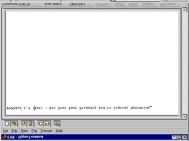
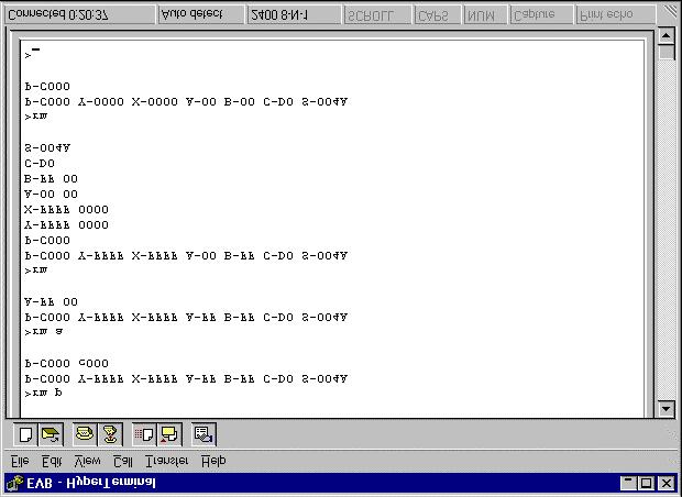
32 Open your hyperterminal connection to the EVB. Power up your EVB and press the EVB RESET button. Note the contents of the screen: BUFFALO-stands for Bit User Fast Friendly Aid to Logical Operations
33
34 Press Enter. This brings up the BUFFALO prompt > You are ready to use the 68HC11EVB.
35 ASM == on-board assembler ASM address Displays the assembly language for specified address. User may change the instruction and/or data. Labels may not be used. Instead, use the actual memory location where the label points to. Use your.lst file for help. Use <CR> to advance to next line of code. Use <CTRL-C> to abort on-board assembly.
36
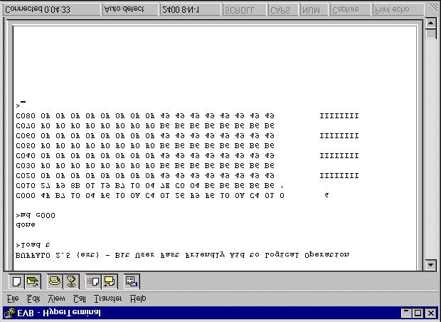
37 G Go / Execute command G address Begins execution of a program at the specific address. The program must provide a jump instruction to get back to the BUFFALO prompt. (jmp $e00a) $E00A is the location of BUFFALO in memory. LOAD T Download an assembled.s19 file from a PC After entering the LOAD T command, go to the Transfer menu:send Text File. Choose the.s19 file you wish to load. When the file is loaded the word done appears on the screen. You can now verify the file was loaded by using the Memory Display command (MD) and then the G command to run your program.
38
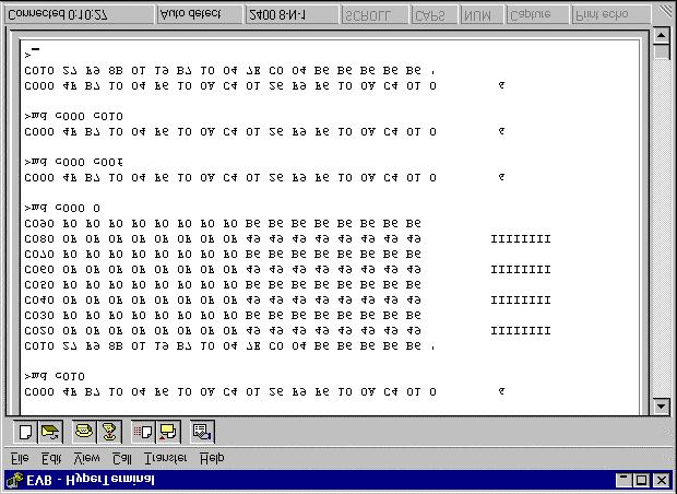
39 MD Memory Display: Display memory to terminal screen MD address_start [address_stop] Displays 16 bytes per line. Display will begin on an even 16 byte memory boundary. If no address_stop is given, 9 lines will be displayed. If address_stop is less than address_start, one line will be displayed.
40
41
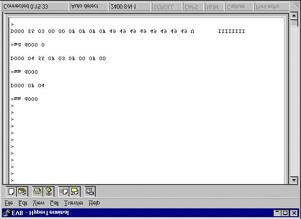
42 MM Memory modify: Display and modify memory contents. MM address Displays memory and gives the user a chance to modify it. Use the <SPACE> key to advance to the next byte. Use CTRL-H to backup one byte. Use <CR> to return to the BUFFALO prompt.
43
44 RM Register Modify: Display and modify 68HC11 registers. RM [p,y,x,a,b,c,s] Displays the contents of the 68HC11 s registers. Also gives the user the chance to modify them. Registers include: P program counter Y index register Y X index register X A Accumulator A B Accumulator B C Condition code register S Stack pointer
45
46 T Trace Instructions T [n] The trace instruction allows the user to execute a program n instructions at a time. The user must set the program counter to the correct starting address before using the trace command. The machine code for the instruction will be displayed along with the registers after each instructions.
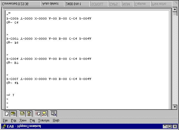
47
Introduction to Microcontrollers II
 Introduction to Microcontrollers II brset, brclr Indexed Addressing Example µp Laboratory #2 BUFFALO Assembling Code EECE 143 Digital Design Project Purpose:To allow students to design their own digital
Introduction to Microcontrollers
 Motorola M68HC11 Specs Assembly Programming Language BUFFALO Topics of Discussion Microcontrollers M68HC11 Package & Pinouts Accumulators Index Registers Special Registers Memory Map I/O Registers Instruction
0b) [2] Can you name 2 people form technical support services (stockroom)?
![0b) [2] Can you name 2 people form technical support services (stockroom)?](/thumbs/92/110229176.jpg "0b) [2] Can you name 2 people form technical support services (stockroom)?") ECE 372 1 st Midterm ECE 372 Midterm Exam Fall 2004 In this exam only pencil/pen are allowed. Please write your name on the front page. If you unstaple the papers write your name on the loose papers also.
ECE 372 1 st Midterm ECE 372 Midterm Exam Fall 2004 In this exam only pencil/pen are allowed. Please write your name on the front page. If you unstaple the papers write your name on the loose papers also.
EE 5340/7340 Motorola 68HC11 Microcontroler Lecture 1. Carlos E. Davila, Electrical Engineering Dept. Southern Methodist University
 EE 5340/7340 Motorola 68HC11 Microcontroler Lecture 1 Carlos E. Davila, Electrical Engineering Dept. Southern Methodist University What is Assembly Language? Assembly language is a programming language
Exam I Review February 2017
 Exam I Review February 2017 Binary Number Representations Conversion of binary to hexadecimal and decimal. Convert binary number 1000 1101 to hexadecimal: Make groups of 4 bits to convert to hexadecimal,
Introduction to Microcontrollers III
 Introduction to Microcontrollers III Timing Functions Delay5u.a11, Delay1m.a11 µp Laboratory #3 Data Entry : µp Laboratory #2 Hints Use the pushbutton routine from count.a11 or count_br.a11 (WAIT0 and
2) [ 2 marks] Both of the following statements cause the value $0300 to be stored in location $1000, but at different times. Explain the difference.
![2) [ 2 marks] Both of the following statements cause the value $0300 to be stored in location $1000, but at different times. Explain the difference.](/thumbs/74/70477363.jpg "2) [ 2 marks] Both of the following statements cause the value $0300 to be stored in location $1000, but at different times. Explain the difference.") 1) [ 9 marks] Write a sequence of directives for an HCS12 assembly language program that performs all of these tasks, in this order: a) Define an array called Measurements starting from memory location
1) [ 9 marks] Write a sequence of directives for an HCS12 assembly language program that performs all of these tasks, in this order: a) Define an array called Measurements starting from memory location
Introduction to Microcontrollers III
 Introduction to Microcontrollers III Timing Functions Delay5u.a11, Delay1m.a11 µp Laboratory #3 Data Entry : µp Laboratory #2 Hints Use the pushbutton routine from count.a11 or count_br.a11 (WAIT0 and
Programming the Motorola MC68HC11 Microcontroller
 Programming the Motorola MC68HC11 Microcontroller COMMON PROGRAM INSTRUCTIONS WITH EXAMPLES aba Add register B to register A Similar commands are abx aby aba add the value in register B to the value in
Most of the HC12 s instructions access data in memory There are several ways for the HC12 to determine which address to access
 HC12 Addressing Modes Instruction coding and execution o Inherent, Extended, Direct, Immediate, Indexed, and Relative Modes o Summary of MC9S12 Addressing Modes o Using X and Y registers as pointers o
Using the stack and the stack pointer
 Using the stack and the stack pointer o The Stack and Stack Pointer o The stack is a memory area for temporary storage o The stack pointer points to the last byte in the stack o Some instructions which
ECE331 Handout 3- ASM Instructions, Address Modes and Directives
 ECE331 Handout 3- ASM Instructions, Address Modes and Directives ASM Instructions Functional Instruction Groups Data Transfer/Manipulation Arithmetic Logic & Bit Operations Data Test Branch Function Call
MC9S12 Assembler Directives A Summary of MC9S12 Instructions Disassembly of MC9S12 op codes. Summary of HCS12 addressing modes ADDRESSING MODES
 MC9S12 Assembler Directives A Summary of MC9S12 Instructions Disassembly of MC9S12 op codes o Review of Addressing Modes o Which branch instruction to use (signed vs unsigned) o Using X and Y registers
What is an Addressing Mode?
 Addressing Modes 1 2 What is an Addressing Mode? An addressing mode is a way in which an operand is specified in an instruction. There are different ways in which an operand may be specified in an instruction.
ME4447/6405. Microprocessor Control of Manufacturing Systems and Introduction to Mechatronics. Instructor: Professor Charles Ume LECTURE 7
 ME4447/6405 Microprocessor Control of Manufacturing Systems and Introduction to Mechatronics Instructor: Professor Charles Ume LECTURE 7 Reading Assignments Reading assignments for this week and next
Decimal, Hexadecimal and Binary Numbers Writing an assembly language program
 Decimal, Hexadecimal and Binary Numbers Writing an assembly language program o Disassembly of MC9S12 op codes o Use flow charts to lay out structure of program o Use common flow structures if-then if-then-else
Lab 2 Part 1 Assembly Language Programming and 9S12 Ports
 Lab 2 Part 1 Assembly Language Programming and 9S12 Ports In this sequence of three labs, you will learn how to write simple assembly language programs for the MC9S12 microcontroller, and how to use general
Introduction to Programming
 Introduction to Programming Chapter 2 Microcontrollers Objectives Describe the difference between source code and machine code. Define opcode, operand, and address of an operand. Explain the purpose of
1. Memory Mapped Systems 2. Adding Unsigned Numbers
 1 Memory Mapped Systems 2 Adding Unsigned Numbers 1 1 Memory Mapped Systems Our system uses a memory space Address bus is 16-bit locations Data bus is 8-bit 2 Adding Unsigned Numbers 2 Our system uses
Ryerson University Department of Electrical and Computer Engineering ELE 538 Microprocessor Systems Final Examination December 8, 2003
 Ryerson University Department of Electrical and Computer Engineering ELE 538 Microprocessor Systems Final Examination December 8, 23 Name: Student Number: Time limit: 3 hours Section: Examiners: K Clowes,
Table 1: Mnemonics Operations Dictionary. Add Accumulators Add B to Y. Add with carry to B. Add Memory to B. Add 16-bit to D And B with Memory
 Table 1: Mnemonics s Dictionary ABA ABX ABY ADCA ADCB ADDA ADDB ADDD ANDA ANDB ASL ASLA ASLB ASLD ASR ASRA ASRB BCC BCLR BCS BEQ BGE BGT BHI BHS BITA BITB BLE BLO BLS BLT Add Accumulators Add B to X Add
instruction 1 Fri Oct 13 13:05:
 instruction Fri Oct :0:0. Introduction SECTION INSTRUCTION SET This section describes the aressing modes and instruction types.. Aressing Modes The CPU uses eight aressing modes for flexibility in accessing
Disassembly of MC9S12 op codes Decimal, Hexadecimal and Binary Numbers
 Disassembly of MC9S12 op codes Decimal, Hexadecimal and Binary Numbers o How to disassemble an MC9S12 instruction sequence o Binary numbers are a code and represent what the programmer intends for the
Disassembly of MC9S12 op codes Decimal, Hexadecimal and Binary Numbers
 Disassembly of MC9S12 op codes Decimal, Hexadecimal and Binary Numbers o How to disassemble an MC9S12 instruction sequence o Binary numbers are a code and represent what the programmer intends for the
The Motorola 68HC11 Instruc5on Set
 The Motorola 68HC11 Instruc5on Set Some Defini5ons A, B * accumulators A and B D * double accumulator (A + B) IX, IY * index registers X and Y SP * stack pointer M * some memory loca5on opr * an operand
Chapter 2: HCS12 Assembly Programming. EE383: Introduction to Embedded Systems University of Kentucky. Samir Rawashdeh
 Chapter 2: HCS12 Assembly Programming EE383: Introduction to Embedded Systems University of Kentucky Samir Rawashdeh With slides based on material by H. Huang Delmar Cengage Learning 1 Three Sections of
Chapter 7 Central Processor Unit (S08CPUV2)
") Chapter 7 Central Processor Unit (S08CPUV2) 7.1 Introduction This section provides summary information about the registers, addressing modes, and instruction set of the CPU of the HCS08 Family. For a more
Chapter 7 Central Processor Unit (S08CPUV2) 7.1 Introduction This section provides summary information about the registers, addressing modes, and instruction set of the CPU of the HCS08 Family. For a more
Lecture 6 Assembly Programming: Branch & Iteration
 CPE 390: Microprocessor Systems Spring 2018 Lecture 6 Assembly Programming: Branch & Iteration Bryan Ackland Department of Electrical and Computer Engineering Stevens Institute of Technology Hoboken, NJ
EE 3170 Microcontroller Applications
 Lecture Overview EE 3170 Microcontroller Applications Lecture 7 : Instruction Subset & Machine Language: Conditions & Branches in Motorola 68HC11 - Miller 2.2 & 2.3 & 2.4 Based on slides for ECE3170 by
Exam 1 Feb. 23, 25, 27?
 Exam 1 Feb. 23, 25, 27? You will be able to use all of the Motorola data manuals on the exam. No calculators will be allowed for the exam. Numbers Decimal to Hex (signed and unsigned) Hex to Decimal (signed
UNIVERSITY OF MANITOBA DEPARTMENT OF ELECTRICAL AND COMPUTER ENGINEERING. Term Test #2 Solution ECE 3610 MICROPROCESSING SYSTEMS
 ECE 3610 Test 2 Solution 1 of 7 PRINT LAST NAME: STUDENT NUMBER PRINT FIRST NAME: UNIVERSITY OF MANITOBA DEPARTMENT OF ELECTRICAL AND COMPUTER ENGINEERING DATE: Feb. 28, 11; TIME: 6:00-8:00 P.M. Term Test
Total: EEL 3701 Digital Logic & Computer Systems Final Exam Fall Semester 2007 COVER SHEET: Re-Grade Information: 1 (10) 2 (10) 3 (10) 4 (14) 5 (14)
 2 (10) 3 (10) 4 (14) 5 (14)") COVER SHEET: Prob. Points: Re-Grade Information: Total: 1 (10) 2 (10) 3 (10) 4 (14) 5 (14) 6 (15) 7 (15) 8 (12) (100) 1 Remember to show ALL work here and in EVERY problem on this exam. [10%] 1. Circuit
COVER SHEET: Prob. Points: Re-Grade Information: Total: 1 (10) 2 (10) 3 (10) 4 (14) 5 (14) 6 (15) 7 (15) 8 (12) (100) 1 Remember to show ALL work here and in EVERY problem on this exam. [10%] 1. Circuit
Lab 8: Debugging Embedded Devices and Software
 Lab 8: Debugging Embedded Devices and Software Summary: Given pre-written code, isolate code and functional errors to create a working memory interfacing program. Learning Objectives: Debug and fix pre-written
Introduction to Programming the 9S12 in C Huang Sections 5.2 and 5.3
 Introduction to Programming the 9S12 in C Huang Sections 5.2 and 5.3 o Comparison of C and Assembly programs for the HC12 o How to compile a C program using the GNU-C compiler o Using pointers to access
History of the Microprocessor. ECE/CS 5780/6780: Embedded System Design. Microcontrollers. First Microprocessors. MC9S12C32 Block Diagram
 History of the Microprocessor ECE/CS 5780/6780: Embedded System Design Chris J. Myers Lecture 1: 68HC12 In 1968, Bob Noyce and Gordon Moore left Fairchild Semiconductor and formed Integrated Electronics
EE 3170 Microcontroller Applications
 Q. 3.9 of HW3 EE 37 Microcontroller Applications (a) (c) (b) (d) Midterm Review: Miller Chapter -3 -The Stuff That Might Be On the Exam D67 (e) (g) (h) CEC23 (i) (f) (j) (k) (l) (m) EE37/CC/Lecture-Review
LECTURE #21: G-CPU & Assembly Code EEL 3701: Digital Logic and Computer Systems Based on lecture notes by Dr. Eric M. Schwartz
 LECTURE #21: G-CPU & Assembly Code EEL 3701: Digital Logic and Computer Systems Based on lecture notes by Dr. Eric M. Schwartz G-CPU Important Notes (see Schwartz s lecture for a general overview) - The
Introduction to Programming the 9S12 in C Huang Sections 5.2 and 5.3. You will be able to use all of the Motorola data manuals on the exam.
 Introduction to Programming the 9S12 in C Huang Sections 5.2 and 5.3 o Comparison of C and Assembly programs for the HC12 o How to compile a C program using the GNU-C compiler o Using pointers to access
HC11 Instruction Set
 HC11 Instruction Set Instruction classes 1. Accumulator and Memory 2. Stack and Index Register 3. Condition Code Register 4. Program control instructions CMPE12 Summer 2009 19-2 1 Accumulator and memory
SECTION 6 CENTRAL PROCESSING UNIT
 SECTION 6 CENTRAL PROCESSING UNIT This section discusses the M68HC11 central processing unit (CPU), which is responsible for executing all software instructions in their programmed sequence. The M68HC11
Homework 12 Solutions
 Page 1/6 1. Here is a short program that shows all addressing modes: We are given a table of student's test scores where there are three scores in a semester per student. Unfortunately, the person who
Cross Assembly and Program Development
 Cross Assembly and ENGG4640/3640; Fall 2004; Prepared by Radu Muresan 1 Introduction Text Editor Program Ex. DOS, Notepad, Word saved as ASCII Source Code Assembler or Cross-Assembler Object Code Machine
538 Lecture Notes Week 3
 538 Lecture Notes Week 3 (Sept. 16, 2013) 1/18 538 Lecture Notes Week 3 Answers to last week's questions 1 Write code so that the least significant bit of Accumulator A is cleared, the most significant
N bit is set if result of operation in negative (MSB = 1) Z bit is set if result of operation is zero (All bits = 0)
 Z bit is set if result of operation is zero (All bits = 0)") Addition and Subtraction of Hexadecimal Numbers. Setting the C (Carry), V (Overflow), N (Negative) and Z (Zero) bits How the C, V, N and Z bits of the CCR are changed Condition Code Register Bits N, Z,
Addition and Subtraction of Hexadecimal Numbers. Setting the C (Carry), V (Overflow), N (Negative) and Z (Zero) bits How the C, V, N and Z bits of the CCR are changed Condition Code Register Bits N, Z,
CMPEN 472 Sample EXAM II
 CMPEN 472 Sample EXAM II Name: Student ID number (last 4 digit): Please write your name on every page. Write your solutions clearly. You may use backside of each page for scratch but the solutions must
A Simple MC9S12 Program
 A Simple MC9S12 Program All programs and data must be placed in memory between address 0x1000 and 0x3BFF. For our programs we will put the first instruction at 0x2000, and the first data byte at 0x1000
C SC 230 Computer Architecture and Assembly Language April 2000 Exam Sample Solutions
 C SC 230 Computer Architecture and Assembly Language April 2000 Exam Sample Solutions 1. (12 marks) Circle the correct answer for each of the following: The 8-bit two's complement representation of -15
CS/ECE 5780/6780: Embedded System Design
 CS/ECE 5780/6780: Embedded System Design John Regehr Lecture 2: 68HC12 Architecture & Lab 1 Introduction Duff s Device void foo (int x, int *y, int *z) { switch (x % 8) { case 0: do { *y++ = *z++; case
AN1745. Interfacing the HC705C8A to an LCD Module By Mark Glenewinkel Consumer Systems Group Austin, Texas. Introduction
 Order this document by /D Interfacing the HC705C8A to an LCD Module By Mark Glenewinkel Consumer Systems Group Austin, Texas Introduction More and more applications are requiring liquid crystal displays
Mark II Aiken Relay Calculator
 Introduction to Embedded Microcomputer Systems Lecture 6.1 Mark II Aiken Relay Calculator 2.12. Tutorial 2. Arithmetic and logical operations format descriptions examples h 8-bit unsigned hexadecimal $00
2. Arithmetic Instructions addition, subtraction, multiplication, divison (HCS12 Core Users Guide, Sections 4.3.4, and ).
.") AS12 Assembler Directives A Summary of 9S12 instructions Disassembly of 9S12 op codes Huang Section 1.8, Chapter 2 MC9S12 V1.5 Core User Guide Version 1.2, Section 12 o A labels is a name assigned the
AS12 Assembler Directives A Summary of 9S12 instructions Disassembly of 9S12 op codes Huang Section 1.8, Chapter 2 MC9S12 V1.5 Core User Guide Version 1.2, Section 12 o A labels is a name assigned the
Input and Output Ports. How do you get data into a computer from the outside?
 Input and Output Ports How do you get data into a computer from the outside? SIMPLIFIED INPUT PORT D 7 Any read from address $0000 gets signals from outside H C 2 D a t a D D D4 D3 S i g n a l s F r o
AN Kbyte Addressing with the M68HC11. Overview
 Order this document by /D 128-Kbyte Addressing with the M68HC11 By Ross Mitchell MCU Applications Engineering Freescale Ltd. East Kilbride, Scotland Overview The maximum direct addressing capability of
TEMPERATURE SENSOR. Revision Class. Instructor / Professor LICENSE
 CME-11E9 EVBU LAB EXPERIMENT TEMPERATURE SENSOR Revision 04.02.11 Class Instructor / Professor LICENSE You may use, copy, modify and distribute this document freely as long as you include this license
ECE 3610 MICROPROCESSING SYSTEMS
 24.361 Lab. 4 31 ECE 3610 MICROPROCESSING SYSTEMS Laboratory 4 LAB 4: ASSEMBLER DIRECTIVES, THE STACK, SUBROUTINES, AND BUBBLE SORTING 1 INTRODUCTION This lab deals with the use of the stack and subroutines
Microcontrollers. Microcontroller
 Microcontrollers Microcontroller A microprocessor on a single integrated circuit intended to operate as an embedded system. As well as a CPU, a microcontroller typically includes small amounts of RAM and
UNIVERSITY OF HONG KONG DEPARTMENT OF ELECTRICAL AND ELECTRONIC ENGINEERING. Principles of Computer Operation
 UNIVERSITY OF HONG KONG DEPARTMENT OF ELECTRICAL AND ELECTRONIC ENGINEERING Experiment PCO: Principles of Computer Operation Location: Part I Lab., CYC 102. Objective: The objective is to learn the basic
AN1742. Programming the 68HC705J1A In-Circuit By Chris Falk CSG Product Engineering Austin, Texas. Introduction. Overview
 Order this document by /D Programming the 68HC705J1A In-Circuit By Chris Falk CSG Product Engineering Austin, Texas Introduction Overview This application note describes how a user can program the 68HC705J1A
HC11 Instruction Set Architecture
 HC11 Instruction Set Architecture High-level HC11 architecture Interrupt logic MEMORY Timer and counter M8601 CPU core Serial I/O A/D converter Port A Port B Port C Port D Port E CMPE12 Summer 2009 16-2
EE 308 Spring The HCS12 has 6 addressing modes
 The HCS12 has 6 addressing modes Most of the HC12 s instructions access data in memory There are several ways for the HC12 to determine which address to access Effective Address: Memory address used by
EMCH 367 Fundamentals of Microcontrollers Example_Sort EXAMPLE SORT
 OBJECTIVE This example has the following objectives: EXAMPLE SORT Review the use of keystroke commands for controlling a process Introduce the concept of multiple sort and its sequential sort equivalent
Introduction to the MC9S12 Hardware Subsystems
 Setting and clearing bits in C Using pointers in C o Program to count the number of negative numbers in an area of memory Introduction to the MC9S12 Hardware Subsystems o The MC9S12 timer subsystem Operators
HC11 Instruction Set Architecture
 HC11 Instruction Set Architecture Summer 2008 High-level HC11 architecture Interrupt logic MEMORY Timer and counter M8601 CPU core Serial I/O A/D converter Port A Port B Port C Port D Port E CMPE12 Summer
ME 6405 Introduction to Mechatronics
 ME 6405 Introduction to Mechatronics Fall 2005 Instructor: Professor Charles Ume LECTURE 9 Homework 1 Solution 1. Write an assembly language program to clear the usable internal RAM in the M68HC11E9. Solution:
UNIVERSITY OF HONG KONG DEPARTMENT OF ELECTRICAL AND ELECTRONIC ENGINEERING
 UNIVERSITY OF HONG KONG DEPARTMENT OF ELECTRICAL AND ELECTRONIC ENGINEERING Experiment PCO: Principles of Computer Operation Location: Part I Lab., CYC 102. Objective: The objective is to learn the basic
MC68705P3 Bootstrap ROM
 MC68705P3 Bootstrap ROM ;This is a listing of the Bootstrap ROM which resides in Motorola's MC68705P3 single chip ;micros. Its sole purpose is to program its own EPROM by copying the data from an external
COE538 Lecture Notes Week 3 (Week of Sept 17, 2012)
") COE538 Lecture Notes: Week 3 1 of 11 COE538 Lecture Notes Week 3 (Week of Sept 17, 2012) Announcements My lecture sections should now be on Blackboard. I've also created a discussion forum (and anonymous
COE538 Lecture Notes: Week 3 1 of 11 COE538 Lecture Notes Week 3 (Week of Sept 17, 2012) Announcements My lecture sections should now be on Blackboard. I've also created a discussion forum (and anonymous
University of Florida EEL 4744 Fall 1998 Dr. Eric M. Schwartz
 Department of Electrical & Computer Engineering 15 October 199 Professor in ECE 31-Dec-9 12:22 PM Page 1/ Instructions: Show all work on the front of the test papers. If you need more room, make a clearly
Lecture #3 Microcontroller Instruction Set Embedded System Engineering Philip Koopman Wednesday, 20-Jan-2015
 Lecture #3 Microcontroller Instruction Set 18-348 Embedded System Engineering Philip Koopman Wednesday, 20-Jan-2015 Electrical& Computer ENGINEERING Copyright 2006-2015, Philip Koopman, All Rights Reserved
Computer Organization I. Lecture 28: Architecture of M68HC11
 Computer Organization I Lecture 28: Architecture of M68HC11 Overview Architecture of HC11 Microprocessor Format of HC11 Assembly Code Objectives To understand the simplified architecture of HC11 To know
ECE 372 Microcontroller Design Basic Assembly Programming. ECE 372 Microcontroller Design Basic Assembly Programming
 For Loop Example: for(j=0; j
Introduction to Embedded Microcomputer Systems Lecture 8.1. Computers in the future may weigh no more than 1.5 tons Popular Science, 1949
 Introduction to Embedded Microcomputer Systems Lecture 8.1 Computers in the future may weigh no more than 1.5 tons Popular Science, 1949 Recap Debugging: Monitor, dump TExaS Real 9S12DG Overview Addition
Practical Course File For
 Practical Course File For Microprocessor (IT 473) B.Tech (IT) IV-SEM Department of IT University Institute of Engineering & Technology Panjab University, Chandigarh Page 1 INTRODUCTION... 4 EXPERIMENT-1:
MC68705U3 Bootstrap ROM
 MC68705U3 Bootstrap ROM ;This is a listing of the Bootstrap ROM which resides in Motorola's MC68705U3 single chip ;micros. Its sole purpose is to program its own EPROM by copying the data from an external
Lab 7: Asynchronous Serial I/O
 CpE 390 Microprocessor Systems Lab 7: Asynchronous Serial I/O 1. Introduction Serial communications is the transfer of data, one bit at a time, over a communications channel. Serial communications can
ECET Chapter 2, Part 3 of 3
 ECET 310-001 Chapter 2, Part 3 of 3 W. Barnes, 9/2006, rev d. 10/07 Ref. Huang, Han-Way, The HCS12/9S12: An Introduction to Software and Hardware Interfacing, Thomson/Delmar. In This Set of Slides: 1.
CPU08RM/AD REV 3 8M68HC08M. CPU08 Central Processor Unit. Reference Manual
 CPU08RM/AD REV 3 68HC08M6 HC08M68HC 8M68HC08M CPU08 Central Processor Unit Reference Manual blank CPU08 Central Processor Unit Reference Manual Motorola reserves the right to make changes without further
ECE 331: PC Lab 3 Stack and Subroutines
 ECE 331: PC Lab 3 Stack and Subroutines Professor Andrew Mason Michigan State University Rev: S11 p.1 Announcements Objectives Topics Outline Review starting and using ASM development environment Pushing
Serial Communication Through an Asynchronous FIFO Buffer
 Serial Communication Through an Asynchronous FIFO Buffer Final Project Report December 9, 2000 E155 Nick Bodnaruk and Andrew Ingram Abstract: For our clinic, we need to be able to use serial communication
Menu Computer Organization Programming Model for the an example microprocessors (the G-CPU & Motorola 68HC11) Assembly Programming Look into my...
 Assembly Programming Look into my...") Menu Computer Organization Programming Model for the an example microprocessors (the G-CPU & Motorola 68HC11) Assembly Programming Look into my... See examples on web: DirAddr.asm, ExtAddr.asm, IndAddr.asm,
Menu Computer Organization Programming Model for the an example microprocessors (the G-CPU & Motorola 68HC11) Assembly Programming Look into my... See examples on web: DirAddr.asm, ExtAddr.asm, IndAddr.asm,
Lab 2 Part 3 Assembly Language Programming and 9S12 Ports
 Lab 2 Part 3 Assembly Language Programming and 9S12 Ports Introduction and Objectives In this week s lab you will write an assembly language program to display various patterns on the eight individual
Addition and Subtraction of Hexadecimal Numbers Simple assembly language programming
 Addition and Subtraction of Hexadecimal Numbers Simple assembly language programming o A simple Assembly Language Program o Assembling an Assembly Language Program o Simple 9S12 programs o Hex code generated
Immediate vs. Extended mode: Immediate values are marked with a # symbol. They also are different instructions when assembled.
 So, you basically didn t study and now you re in the final and you hope to pass this test and save your miserable grade... And you expect this cheat sheet to save you? Well, I sincerely hope it does. Slacker.
Application Note. Interfacing the CS5525/6/9 to the 68HC05. By Keith Coffey MOSI (PD3) SDO MISO (PD2) SCLK. Figure 1. 3-Wire and 4-Wire Interfaces
 SDO MISO (PD2) SCLK. Figure 1. 3-Wire and 4-Wire Interfaces") Application Note Interfacing the CS5525/6/9 to the 68HC05 By Keith Coffey INTRODUCTION This application note details the interface of Crystal Semiconductor s CS5525/6/9 Analog-to-Digital Converter (ADC)
Application Note Interfacing the CS5525/6/9 to the 68HC05 By Keith Coffey INTRODUCTION This application note details the interface of Crystal Semiconductor s CS5525/6/9 Analog-to-Digital Converter (ADC)
EE 308 LAB 1 ASSEMBLER, SIMULATOR, AND MONITOR. Introduction and Objectives
 EE 308 LAB 1 ASSEMBLER, SIMULATOR, AND MONITOR Introduction and Objectives This laboratory introduces you to the following 68HC12 assembly language programming tools: The 68HC12 assembler CA6812. This
538 Lecture Notes Week 1
 538 Clowes Lecture Notes Week 1 (Sept. 6, 2017) 1/10 538 Lecture Notes Week 1 Announcements No labs this week. Labs begin the week of September 11, 2017. My email: kclowes@ryerson.ca Counselling hours:
Lecture 7 Assembly Programming: Shift & Logical
 CPE 390: Microprocessor Systems Fall 2017 Lecture 7 Assembly Programming: Shift & Logical Bryan Ackland Department of Electrical and Computer Engineering Stevens Institute of Technology Hoboken, NJ 07030
Teaching and Curriculum Development of Microprocessor Classes
 Session 2559 Teaching and Curriculum Development of Microprocessor Classes Roman Stemprok University of North Texas Abstract This paper addresses teaching and curriculum development for several microprocessor
Application Note. Interfacing the CS5521/22/23/24/28 to the 68HC05. Figure 1. 3-Wire and 4-Wire Interfaces
 Application Note Interfacing the CS5521/22/23/24/28 to the 68HC05 TABLE OF CONTENTS 1. INTRODUCTION... 1 2. ADC DIGITAL INTERFACE... 1 3. SOFTWARE DESCRIPTION... 2 3.1 Initialize... 2 3.2 Write Channel
Sample Problem Set #1
 Sample Problem Set #1 Notes: These problems are typical exam problems; most are drawn from previous homeworks and exams. This exam is open book, open notes. It may help to have a calculator. For partial
CHAPTER 8. Solutions for Exercises
 CHAPTER 8 Solutions for Exercises E8.1 The number of bits in the memory addresses is the same as the address bus width, which is 20. Thus the number of unique addresses is 2 20 = 1,048,576 = 1024 1024
COSC 243. Instruction Sets And Addressing Modes. Lecture 7&8 Instruction Sets and Addressing Modes. COSC 243 (Computer Architecture)
") COSC 243 Instruction Sets And Addressing Modes 1 Overview This Lecture Source Chapters 12 & 13 (10 th editition) Textbook uses x86 and ARM (we use 6502) Next 2 Lectures Assembly language programming 2
COSC 243 Instruction Sets And Addressing Modes 1 Overview This Lecture Source Chapters 12 & 13 (10 th editition) Textbook uses x86 and ARM (we use 6502) Next 2 Lectures Assembly language programming 2
ECE L A B 1 Introduction ASSEMBLY PROGRAMMING WITH MINIIDE
 L A B 1 Introduction ASSEMBLY PROGRAMMING WITH MINIIDE The purpose of this lab is to introduce you to the layout and structure of Assembly Language programs and their format. You will write your own programs
ECE 3610 MICROPROCESSING SYSTEMS AN ENCRYPTED ASCII CODE DECODER
 ECE 3610 MICROPROCESSIG SYSTEMS A ECRYPTED ASCII CODE DECODER 1 PROBLEM SPECIFICATIO Design a microprocessing system to decode messages which are encrypted. Each byte of the message is an encrypted ASCII
MC68HC12 Parallel I/O
 EEL 4744C: Microprocessor Applications Lecture 6 Part 2 MC68HC12 Parallel I/O Dr. Tao Li 1 Software and Hardware Engineering (new version): Chapter 11 Or SHE (old version): Chapter 7 And Reading Assignment
538 Lecture Notes Week 5
 538 Lecture Notes Week 5 (Sept. 30, 2013) 1/15 538 Lecture Notes Week 5 Answers to last week's questions 1. With the diagram shown for a port (single bit), what happens if the Direction Register is read?
Addition and Subtraction of Hexadecimal Numbers Simple assembly language programming
 Addition and Subtraction of Hexadecimal Numbers Simple assembly language programming o A simple Assembly Language Program o Assembling an Assembly Language Program o Simple 9S12 programs o Hex code generated
538 Lecture Notes Week 5
 538 Lecture Notes Week 5 (October 4, 2017) 1/18 538 Lecture Notes Week 5 Announements Midterm: Tuesday, October 25 Answers to last week's questions 1. With the diagram shown for a port (single bit), what
CE-320 Microcomputers I Winter 2010 LAB 1: MINIIDE GROUP #: NAME: PARTNER: Lab 1 Page 1
 LAB 1: MINIIDE GROUP #: NAME: PARTNER: Lab 1 Page 1 LAB 1: MINIIDE GOALS Understand Wytec s Dragon12+ evaluation board Know how to use Dragon12 commands Understand an integrated development environment
EE4390 Microprocessors
 EE4390 Microprocessors Lesson 6,7 Instruction Set, Branch Instructions, Assembler Directives Revised: Aug 1, 2003 1 68HC12 Instruction Set An instruction set is defined as a set of instructions that a