Total: EEL 3701 Digital Logic & Computer Systems Final Exam Fall Semester 2007 COVER SHEET: Re-Grade Information: 1 (10) 2 (10) 3 (10) 4 (14) 5 (14)
|
|
|
- Brianna Burns
- 6 years ago
- Views:
Transcription
1 COVER SHEET: Prob. Points: Re-Grade Information: Total: 1 (10) 2 (10) 3 (10) 4 (14) 5 (14) 6 (15) 7 (15) 8 (12) (100) 1
2 Remember to show ALL work here and in EVERY problem on this exam. [10%] 1. Circuit Analysis What is the logic equation for X in the given circuit? Do not simplify or transform it into an SOP or POS form. Leave the logic expression as it is after analysis. Also, draw the intermediate expression at the input to each gate. Notation reminder: A(H) is the same as A.H Boolean expression answers must be in lexical order, i.e., /A before A, A before B, etc. EQUATION: X = A(L) B(H) C(H) D(L) E(L) X(L) A(L) C(H) B(L) A(L) B(H) 2
3 [10%] 2. Circuit Synthesis Draw a mixed-logic circuit diagram (with the minimum number of gates) to directly implement the below equation. All inputs and the output can be of any activation-level desired. Be sure to specify the desired activation levels. Do not simplify this equation. You may only use gates available on 74HC10 chips (shown). Use as many 74HC10 chips as you need, but use the minimum number required to solve this problem. 10 F=A*B*D + B*/C*/E + /A*C*/D 3
4 [10%] 3. Implementation of an ASM chart using clocked S-R FFs S-R characteristic table: S R Q Q ? 1 1 1? (a) Given the above ASM chart, complete the following block diagram of its implementation using the minimum number of clocked S-R flip-flops: (2%) Determine how many clocked S-R flip-flops that are needed. Draw in all the inputs and outputs of the combinatorial circuit. Make all necessary connections to complete the block diagram (between the combinatorial circuit and the clocked S-R flip-flops). Combinatorial circuit (Inputs) (Outputs) (Draw flip-flops here.) 4
5 3. (continued) (ASM chart is repeated here for your convenience) S-R characteristic table: S R Q Q ? 1 1 1? (b) Finish the implementation of the ASM by determining the minimum sum-of-products (MSOP) logic expressions for all the output signals: (8%) (If necessary, use the bottom/back of the previous page to do your work.) 5
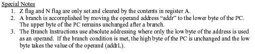
6 [14%] 4. Assume the below has already been run, and the code that follows in a, b, c, d, e, f, g will follow. Hand assemble the following instructions and fill in the blanks. EA is the 16-bit effective address. If there is no effective address, write none. (Use the G-CPU instruction set attached to this test). ORG $0032 ORG $0048 Data0 DC.B $66 Data6 DC.B $3E ORG $0028 ORG $0058 Data1 DC.B $A3 Data7 DC.B $9E ORG $002A ORG $2A42 Data2 DC.B $74 Data8 DC.B $99AC ORG $0038 Data3 DC.B $EC ORG $0000 ORG $003A LDX #$000A Data4 DC.B $EC LDAA #3 ORG $0040 LDAB #37 Data5 DC.B $AB SUM_AB ADDRESS INSTRUCTION HEX ADDRESS HEX VALUE a) $0008 STAB 48,X _0008 EA = 0009 Value stored = 000A _000B b) $0008 LDAA 40 _0008 EA = 0009 A = 000A _000B c) $0008 LDX #Data8 _0008 EA = 0009 X = 000A _000B d) $0008 TBA _0008 EA = 0009 A = 000A _000B e) $0008 LDAB Data8 _0008 EA = 0009 B = 000A _000B f) $0008 BN $EF _0008 EA = 0009 PC after this _000A instruction = 000B g) $0008 BNE $EF _0008 EA = 0009 PC after this _000A instruction = 000B 6
7 [14%] 5. EEPROM and SRAM Given as many 256x8 EEPROM chips and 256x8 static RAM chips as needed, design a 1024x8 memory module (with a CS) that has 512x8 of RAM at the lowest addresses and 512x8 of EEPROM at the highest addresses. The 512x8 of RAM must start at address 0 and the first address of the 512x8 of EEPROM must immediately follow the last RAM address. Add the minimum number of additional components required. Make sure the EEPROM is NEVER enabled during a write cycle and the RAM is enabled for both read and write cycles. The EEPROM and SRAM devices have active low CS and the SRAM devices have a R/W control signal. (2%) a) What is the address range for each of the memory components (in binary and in hex)? SRAM EEPROM (12%) b) Design the required memory device below. Make sure you show the memory module s inputs and outputs and all the individual memory component devices. Use labels instead of wires in the design. 7
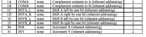
8 [15%] 6. HAND Assembly The following program finds all occurrences of $37 in a table with an $FF end of table marker and replaces them with $AA. It uses the G-CPU instruction set attached to this test. Hand assemble the program in the space given. Address (Hex) Data (Hex) Program ORG $100 Table DC.B $10,$37,$CC,$37,$15 EOT DC.B $FF NEW EQU $AA OLD EQU $C8 ORG $200 STRT LDX #Table LOOP LDAB EOT COMB LDAA 0,X SUM_BA BEQ QUIT LDAA 0,X LDAB #OLD SUM_BA BNE NOSW LDAA #NEW STAA 0,X NOSW INX BNE LOOP QUIT BEQ QUIT 8
9 [15%] 7. GCPU Assembly Programming (Use the G-CPU instruction set attached to this test) Write an entire G-CPU program to copy all the positive values in a table called TAB1 (beginning at address $3000) to another table called TAB2 (beginning at address $7000). TAB1 has byte values already in memory. There is a 16-KB ROM for your program, starting at address 0 and a 32-KB SRAM, starting at $4000 for data. Be sure to initialize all necessary values, variables, etc., i.e., assume no initializations are done for you. Be sure to properly terminate the program (so it does not execute past the end of your program). Use labels instead of numbers in assembly instructions wherever possible. Labels Instructions Comments 9
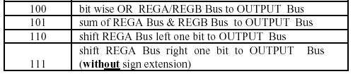
10 [12%] 8. GCPU Instruction Design (See the G-CPU Next State Table attached to this test) We want to implement a new instruction for the GCPU. The new instruction will be denoted as SBAM addr. It added the content of register B to register A (like SUM_BA). But, it also stores the result into memory at location addr. The new opcode for this instruction will be designated as $32 and the next state available in the Controller s ASM is $34. Show the additional states required to implement this new instruction in the Controller s ASM below and show all controller output signals that must be true in each new state for this new instruction: Assume: R/-W is True for Read and False for Write. Control Signals: PC_INC, PC_LD_Upper, PC_LD_Lower, MAR_INC, MAR_LD_Upper, MAR_LD_Lower, X_INC, X_LD_Upper, X_LD_Lower, Y_INC, Y_LD_Upper, Y_LD_Lower, IR_LD, R/-W, ADDR_SEL1:0, XD_LD, YD_LD Note1: The controller output signals are also shown in the G CPU Block Diagram for reference. Fill in the ASM for SBAM $addr (12 pts.): State = IR_LD = T R/-W = T Existing G CPU Instructions R/-W = T IR5:0 SBAM $addr Opcode = $32 10
11 GCPU Instructions 11


12 GCPU Block Diagram 12


13 Partial GCPU Next State Table 13
Y = (A + C) (A + B) (B + C)
 (A + B) (B + C)") EEL3701 Dr. Gugel Last Name First Name Spring 2012 Final Quiz UF ID# Open book and open notes, 90-minute examination to be done in non-red pencil or pen. No electronic devices permitted. All work and solutions
EEL3701 Dr. Gugel Last Name First Name Spring 2012 Final Quiz UF ID# Open book and open notes, 90-minute examination to be done in non-red pencil or pen. No electronic devices permitted. All work and solutions
Homework 12 Solutions
 Page 1/6 1. Here is a short program that shows all addressing modes: We are given a table of student's test scores where there are three scores in a semester per student. Unfortunately, the person who
LECTURE #21: G-CPU & Assembly Code EEL 3701: Digital Logic and Computer Systems Based on lecture notes by Dr. Eric M. Schwartz
 LECTURE #21: G-CPU & Assembly Code EEL 3701: Digital Logic and Computer Systems Based on lecture notes by Dr. Eric M. Schwartz G-CPU Important Notes (see Schwartz s lecture for a general overview) - The
Menu Computer Organization Programming Model for the an example microprocessors (the G-CPU & Motorola 68HC11) Assembly Programming Look into my...
 Assembly Programming Look into my...") Menu Computer Organization Programming Model for the an example microprocessors (the G-CPU & Motorola 68HC11) Assembly Programming Look into my... See examples on web: DirAddr.asm, ExtAddr.asm, IndAddr.asm,
Menu Computer Organization Programming Model for the an example microprocessors (the G-CPU & Motorola 68HC11) Assembly Programming Look into my... See examples on web: DirAddr.asm, ExtAddr.asm, IndAddr.asm,
EE 5340/7340 Motorola 68HC11 Microcontroler Lecture 1. Carlos E. Davila, Electrical Engineering Dept. Southern Methodist University
 EE 5340/7340 Motorola 68HC11 Microcontroler Lecture 1 Carlos E. Davila, Electrical Engineering Dept. Southern Methodist University What is Assembly Language? Assembly language is a programming language
1. Memory Mapped Systems 2. Adding Unsigned Numbers
 1 Memory Mapped Systems 2 Adding Unsigned Numbers 1 1 Memory Mapped Systems Our system uses a memory space Address bus is 16-bit locations Data bus is 8-bit 2 Adding Unsigned Numbers 2 Our system uses
ME4447/6405. Microprocessor Control of Manufacturing Systems and Introduction to Mechatronics. Instructor: Professor Charles Ume LECTURE 7
 ME4447/6405 Microprocessor Control of Manufacturing Systems and Introduction to Mechatronics Instructor: Professor Charles Ume LECTURE 7 Reading Assignments Reading assignments for this week and next
Go Gators! Relax! May the Schwartz be with you!
 Page 1/12 Exam 1 Instructions: Turn off cell phones beepers and other noise making devices. Show all work on the front of the test papers. If you need more room make a clearly indicated note on the front
Good Evening! Welcome!
 University of Florida EEL 3701 Fall 2011 Dr Eric M Schwartz Page 1/11 Exam 2 Instructions: Turn off all cell phones, beepers and other noise making devices Show all work on the front of the test papers
Problem Points Your Points Total 80
 Grades: 20% of the final grade. CDA 3103 Computer Organization Exam 2 Solution Set Name: USF ID: Problem Points Your Points 1 10 2 10 3 20 4 10 5 15 6 15 Total 80 Exam Rules Close book, notes and HW. Only
ECE331 Handout 3- ASM Instructions, Address Modes and Directives
 ECE331 Handout 3- ASM Instructions, Address Modes and Directives ASM Instructions Functional Instruction Groups Data Transfer/Manipulation Arithmetic Logic & Bit Operations Data Test Branch Function Call
Ryerson University Department of Electrical and Computer Engineering ELE 538 Microprocessor Systems Final Examination December 8, 2003
 Ryerson University Department of Electrical and Computer Engineering ELE 538 Microprocessor Systems Final Examination December 8, 23 Name: Student Number: Time limit: 3 hours Section: Examiners: K Clowes,
2) [ 2 marks] Both of the following statements cause the value $0300 to be stored in location $1000, but at different times. Explain the difference.
![2) [ 2 marks] Both of the following statements cause the value $0300 to be stored in location $1000, but at different times. Explain the difference.](/thumbs/74/70477363.jpg "2) [ 2 marks] Both of the following statements cause the value $0300 to be stored in location $1000, but at different times. Explain the difference.") 1) [ 9 marks] Write a sequence of directives for an HCS12 assembly language program that performs all of these tasks, in this order: a) Define an array called Measurements starting from memory location
1) [ 9 marks] Write a sequence of directives for an HCS12 assembly language program that performs all of these tasks, in this order: a) Define an array called Measurements starting from memory location
Cross Assembly and Program Development
 Cross Assembly and ENGG4640/3640; Fall 2004; Prepared by Radu Muresan 1 Introduction Text Editor Program Ex. DOS, Notepad, Word saved as ASCII Source Code Assembler or Cross-Assembler Object Code Machine
University of Florida EEL 4744 Fall 1998 Dr. Eric M. Schwartz
 Department of Electrical & Computer Engineering 15 October 199 Professor in ECE 31-Dec-9 12:22 PM Page 1/ Instructions: Show all work on the front of the test papers. If you need more room, make a clearly
Decimal, Hexadecimal and Binary Numbers Writing an assembly language program
 Decimal, Hexadecimal and Binary Numbers Writing an assembly language program o Disassembly of MC9S12 op codes o Use flow charts to lay out structure of program o Use common flow structures if-then if-then-else
UNIVERSITY OF HONG KONG DEPARTMENT OF ELECTRICAL AND ELECTRONIC ENGINEERING. Principles of Computer Operation
 UNIVERSITY OF HONG KONG DEPARTMENT OF ELECTRICAL AND ELECTRONIC ENGINEERING Experiment PCO: Principles of Computer Operation Location: Part I Lab., CYC 102. Objective: The objective is to learn the basic
Introduction to Microcontrollers II
 Introduction to Microcontrollers II brset, brclr Indexed Addressing Example µp Laboratory #2 BUFFALO Assembling Code EECE 143 Digital Design Project Purpose: To allow students to design their own digital
Mark II Aiken Relay Calculator
 Introduction to Embedded Microcomputer Systems Lecture 6.1 Mark II Aiken Relay Calculator 2.12. Tutorial 2. Arithmetic and logical operations format descriptions examples h 8-bit unsigned hexadecimal $00
Introduction to Microcontrollers
 Motorola M68HC11 Specs Assembly Programming Language BUFFALO Topics of Discussion Microcontrollers M68HC11 Package & Pinouts Accumulators Index Registers Special Registers Memory Map I/O Registers Instruction
Introduction to the 9S12 Microcontroller
 Introduction to the 9S12 Microcontroller o Harvard architecture and Princeton architecture o Memory map for a Princeton architecture microprocessor o 68HC12 Address Space o 68HC12 ALU o 68HC12 Programming
Introduction to Microcontrollers II
 Introduction to Microcontrollers II brset, brclr Indexed Addressing Example µp Laboratory #2 BUFFALO Assembling Code EECE 143 Digital Design Project Purpose:To allow students to design their own digital
MC68HC12 Parallel I/O
 EEL 4744C: Microprocessor Applications Lecture 6 Part 2 MC68HC12 Parallel I/O Dr. Tao Li 1 Software and Hardware Engineering (new version): Chapter 11 Or SHE (old version): Chapter 7 And Reading Assignment
UNIVERSITY OF HONG KONG DEPARTMENT OF ELECTRICAL AND ELECTRONIC ENGINEERING
 UNIVERSITY OF HONG KONG DEPARTMENT OF ELECTRICAL AND ELECTRONIC ENGINEERING Experiment PCO: Principles of Computer Operation Location: Part I Lab., CYC 102. Objective: The objective is to learn the basic
ME 6405 Introduction to Mechatronics
 ME 6405 Introduction to Mechatronics Fall 2005 Instructor: Professor Charles Ume LECTURE 9 Homework 1 Solution 1. Write an assembly language program to clear the usable internal RAM in the M68HC11E9. Solution:
CMPEN 472 Sample EXAM II
 CMPEN 472 Sample EXAM II Name: Student ID number (last 4 digit): Please write your name on every page. Write your solutions clearly. You may use backside of each page for scratch but the solutions must
Programming the Motorola MC68HC11 Microcontroller
 Programming the Motorola MC68HC11 Microcontroller COMMON PROGRAM INSTRUCTIONS WITH EXAMPLES aba Add register B to register A Similar commands are abx aby aba add the value in register B to the value in
Introduction to Embedded Systems and Chapter 1: Introduction to HCS12/MC9S12. EE383: Introduction to Embedded Systems University of Kentucky
 Introduction to Embedded Systems and Chapter 1: Introduction to HCS12/MC9S12 EE383: Introduction to Embedded Systems University of Kentucky Samir Rawashdeh With slides based on material by H. Huang Delmar
ECE L A B 1 Introduction ASSEMBLY PROGRAMMING WITH MINIIDE
 L A B 1 Introduction ASSEMBLY PROGRAMMING WITH MINIIDE The purpose of this lab is to introduce you to the layout and structure of Assembly Language programs and their format. You will write your own programs
Input and Output Ports. How do you get data into a computer from the outside?
 Input and Output Ports How do you get data into a computer from the outside? SIMPLIFIED INPUT PORT D 7 Any read from address $0000 gets signals from outside H C 2 D a t a D D D4 D3 S i g n a l s F r o
ECE 3610 MICROPROCESSING SYSTEMS AN ENCRYPTED ASCII CODE DECODER
 ECE 3610 MICROPROCESSIG SYSTEMS A ECRYPTED ASCII CODE DECODER 1 PROBLEM SPECIFICATIO Design a microprocessing system to decode messages which are encrypted. Each byte of the message is an encrypted ASCII
Sample Problem Set #1
 Sample Problem Set #1 Notes: These problems are typical exam problems; most are drawn from previous homeworks and exams. This exam is open book, open notes. It may help to have a calculator. For partial
MC9S12 Address Space
 MC9S12 Address Space MC9S12 has 16 address lines MC9S12 can address 2 16 distinct locations For MC9S12, each location holds one byte (eight bits) MC9S12 can address 2 16 bytes 2 16 = 65536 2 16 = 2 6 2
Code No: R Set No. 1
 Code No: R059210504 Set No. 1 II B.Tech I Semester Supplementary Examinations, February 2007 DIGITAL LOGIC DESIGN ( Common to Computer Science & Engineering, Information Technology and Computer Science
CS303 LOGIC DESIGN FINAL EXAM
 JANUARY 2017. CS303 LOGIC DESIGN FINAL EXAM STUDENT NAME & ID: DATE: Instructions: Examination time: 100 min. Write your name and student number in the space provided above. This examination is closed
Lab 2 Part 1 Assembly Language Programming and 9S12 Ports
 Lab 2 Part 1 Assembly Language Programming and 9S12 Ports In this sequence of three labs, you will learn how to write simple assembly language programs for the MC9S12 microcontroller, and how to use general
Introduction to Programming
 Introduction to Programming Chapter 2 Microcontrollers Objectives Describe the difference between source code and machine code. Define opcode, operand, and address of an operand. Explain the purpose of
Addition and Subtraction of Hexadecimal Numbers Simple assembly language programming
 Addition and Subtraction of Hexadecimal Numbers Simple assembly language programming o A simple Assembly Language Program o Assembling an Assembly Language Program o Simple 9S12 programs o Hex code generated
Introduction to Programming the 9S12 in C Huang Sections 5.2 and 5.3. You will be able to use all of the Motorola data manuals on the exam.
 Introduction to Programming the 9S12 in C Huang Sections 5.2 and 5.3 o Comparison of C and Assembly programs for the HC12 o How to compile a C program using the GNU-C compiler o Using pointers to access
EE319 K Lecture 3. Introduction to the 9S12 Lab 1 Discussion Using the TExaS simulator. University of Texas ECE
 EE319 K Lecture 3 Introduction to the 9S12 Lab 1 Discussion Using the TExaS simulator University of Texas ECE Introduction (von Neumann architecture) processor Bus Memory Mapped I/O System Input Devices
ECE 3610 MICROPROCESSING SYSTEMS
 24.361 Lab. 4 31 ECE 3610 MICROPROCESSING SYSTEMS Laboratory 4 LAB 4: ASSEMBLER DIRECTIVES, THE STACK, SUBROUTINES, AND BUBBLE SORTING 1 INTRODUCTION This lab deals with the use of the stack and subroutines
Exam 1 Feb. 23, 25, 27?
 Exam 1 Feb. 23, 25, 27? You will be able to use all of the Motorola data manuals on the exam. No calculators will be allowed for the exam. Numbers Decimal to Hex (signed and unsigned) Hex to Decimal (signed
MC9S12 Assembler Directives A Summary of MC9S12 Instructions Disassembly of MC9S12 op codes. Summary of HCS12 addressing modes ADDRESSING MODES
 MC9S12 Assembler Directives A Summary of MC9S12 Instructions Disassembly of MC9S12 op codes o Review of Addressing Modes o Which branch instruction to use (signed vs unsigned) o Using X and Y registers
6.1 Combinational Circuits. George Boole ( ) Claude Shannon ( )
 Claude Shannon ( )") 6. Combinational Circuits George Boole (85 864) Claude Shannon (96 2) Signals and Wires Digital signals Binary (or logical ) values: or, on or off, high or low voltage Wires. Propagate digital signals
6. Combinational Circuits George Boole (85 864) Claude Shannon (96 2) Signals and Wires Digital signals Binary (or logical ) values: or, on or off, high or low voltage Wires. Propagate digital signals
Lecture 6 Assembly Programming: Branch & Iteration
 CPE 390: Microprocessor Systems Spring 2018 Lecture 6 Assembly Programming: Branch & Iteration Bryan Ackland Department of Electrical and Computer Engineering Stevens Institute of Technology Hoboken, NJ
QUESTION BANK FOR TEST
 CSCI 2121 Computer Organization and Assembly Language PRACTICE QUESTION BANK FOR TEST 1 Note: This represents a sample set. Please study all the topics from the lecture notes. Question 1. Multiple Choice
N bit is set if result of operation in negative (MSB = 1) Z bit is set if result of operation is zero (All bits = 0)
 Z bit is set if result of operation is zero (All bits = 0)") Addition and Subtraction of Hexadecimal Numbers. Setting the C (Carry), V (Overflow), N (Negative) and Z (Zero) bits How the C, V, N and Z bits of the CCR are changed Condition Code Register Bits N, Z,
Addition and Subtraction of Hexadecimal Numbers. Setting the C (Carry), V (Overflow), N (Negative) and Z (Zero) bits How the C, V, N and Z bits of the CCR are changed Condition Code Register Bits N, Z,
Using the stack and the stack pointer
 Using the stack and the stack pointer o The Stack and Stack Pointer o The stack is a memory area for temporary storage o The stack pointer points to the last byte in the stack o Some instructions which
EE 3170 Microcontroller Applications
 EE 3170 Microcontroller Applications Lecture 4 : Processors, Computers, and Controllers - 1.2 (reading assignment), 1.3-1.5 Based on slides for ECE3170 by Profs. Kieckhafer, Davis, Tan, and Cischke Outline
The 9S12 in Expanded Mode - Using MSI logic to build ports Huang Chapter 14
 The 9S12 in Expanded Mode - Using MSI logic to build ports Huang Chapter 14 Using MSI Logic To Build An Output Port Many designs use standard MSI logic for microprocessor expansion This provides an inexpensive
ECE 372 Microcontroller Design Assembly Programming Arrays. ECE 372 Microcontroller Design Assembly Programming Arrays
 Assembly Programming Arrays Assembly Programming Arrays Array For Loop Example: unsigned short a[]; for(j=; j
What is an Addressing Mode?
 Addressing Modes 1 2 What is an Addressing Mode? An addressing mode is a way in which an operand is specified in an instruction. There are different ways in which an operand may be specified in an instruction.
CodeWarrior. Microcomputer Architecture and Interfacing Colorado School of Mines Professor William Hoff
 CodeWarrior 1 Assembler An assembler is a program that translates assembly language into machine code. Machine code are the numbers that the CPU recognizes as instructions. $B6 $10 $00 Assembly language
BINARY LOAD AND PUNCH
 BINARY LOAD AND PUNCH To easily decrease the amount of time it takes to load a long tape (Cassette or paper) a BINARY formatting technique can be used instead of the conventional ASCII format used by the
History of the Microprocessor. ECE/CS 5780/6780: Embedded System Design. Microcontrollers. First Microprocessors. MC9S12C32 Block Diagram
 History of the Microprocessor ECE/CS 5780/6780: Embedded System Design Chris J. Myers Lecture 1: 68HC12 In 1968, Bob Noyce and Gordon Moore left Fairchild Semiconductor and formed Integrated Electronics
Lab 8: Debugging Embedded Devices and Software
 Lab 8: Debugging Embedded Devices and Software Summary: Given pre-written code, isolate code and functional errors to create a working memory interfacing program. Learning Objectives: Debug and fix pre-written
It translates (converts) assembly language to machine code.
 assembly language to machine code.") Assemblers 1 It translates (converts) assembly language to machine code. Example: LDAA $0180 Uses an instruction set manual: Tests/Final Exam. B6 01 80 Use software: Like the IDE in the Lab. 2 Assembler:
Assemblers 1 It translates (converts) assembly language to machine code. Example: LDAA $0180 Uses an instruction set manual: Tests/Final Exam. B6 01 80 Use software: Like the IDE in the Lab. 2 Assembler:
ECE 331: PC Lab 3 Stack and Subroutines
 ECE 331: PC Lab 3 Stack and Subroutines Professor Andrew Mason Michigan State University Rev: S11 p.1 Announcements Objectives Topics Outline Review starting and using ASM development environment Pushing
DIGITAL SYSTEM FUNDAMENTALS (ECE421) DIGITAL ELECTRONICS FUNDAMENTAL (ECE422)
 DIGITAL ELECTRONICS FUNDAMENTAL (ECE422)") COURSE / CODE DIGITAL SYSTEM FUNDAMENTALS (ECE421) DIGITAL ELECTRONICS FUNDAMENTAL (ECE422) Memory In computing, memory refers to the computer hardware devices used to store information for immediate use
COURSE / CODE DIGITAL SYSTEM FUNDAMENTALS (ECE421) DIGITAL ELECTRONICS FUNDAMENTAL (ECE422) Memory In computing, memory refers to the computer hardware devices used to store information for immediate use
EE 3170 Microcontroller Applications
 Q. 3.9 of HW3 EE 37 Microcontroller Applications (a) (c) (b) (d) Midterm Review: Miller Chapter -3 -The Stuff That Might Be On the Exam D67 (e) (g) (h) CEC23 (i) (f) (j) (k) (l) (m) EE37/CC/Lecture-Review
Exam 2 E2-1 Fall Name: Exam 2
 Exam 2 E2-1 Fall 2004 1. Short Answer [20 pts] Exam 2 a. [4 points] Show the contents of registers A, B, SP, and X after the following code executes: lds #$a00 ldab #$23 A = ldaa #$87 ldx #$2543 B = pshd
Memory and Programmable Logic
 Memory and Programmable Logic Memory units allow us to store and/or retrieve information Essentially look-up tables Good for storing data, not for function implementation Programmable logic device (PLD),
Unit 6 1.Random Access Memory (RAM) Chapter 3 Combinational Logic Design 2.Programmable Logic
 Chapter 3 Combinational Logic Design 2.Programmable Logic") EE 200: Digital Logic Circuit Design Dr Radwan E Abdel-Aal, COE Unit 6.Random Access Memory (RAM) Chapter 3 Combinational Logic Design 2. Logic Logic and Computer Design Fundamentals Part Implementation
EE 200: Digital Logic Circuit Design Dr Radwan E Abdel-Aal, COE Unit 6.Random Access Memory (RAM) Chapter 3 Combinational Logic Design 2. Logic Logic and Computer Design Fundamentals Part Implementation
University of Toronto Faculty of Applied Science and Engineering Edward S. Rogers Sr. Department of Electrical and Computer Engineering
 University of Toronto Faculty of Applied Science and Engineering Edward S. Rogers Sr. Department of Electrical and Computer Engineering Final Examination ECE 241F - Digital Systems Examiners: S. Brown,
A Simple MC9S12 Program
 A Simple MC9S12 Program All programs and data must be placed in memory between address 0x1000 and 0x3BFF. For our programs we will put the first instruction at 0x2000, and the first data byte at 0x1000
Addition and Subtraction of Hexadecimal Numbers Simple assembly language programming
 Addition and Subtraction of Hexadecimal Numbers Simple assembly language programming o A simple Assembly Language Program o Assembling an Assembly Language Program o Simple 9S12 programs o Hex code generated
The 9S12 in Expanded Mode - How to get into expanded mode Huang Chapter 14
 The 9S2 in Expanded Mode - How to get into expanded mode Huang Chapter 4 DATA/ADDR (6) HCS2 _ R/W E LSTRB DEMUX ADDR(6) CE _ WE CS _ UB _ LB DATA ADDR CE - Output Enable (Read) _ WE Write Enable CS Chip
Lecture 5 Assembly Programming: Arithmetic
 CPE 390: Microprocessor Systems Spring 2018 Lecture 5 Assembly Programming: Arithmetic Bryan Ackland Department of Electrical and Computer Engineering Stevens Institute of Technology Hoboken, NJ 07030
LAB 7: G-CPU: Assembly Programming and Hand Assembly
 Page 1/5 OBJECTIVE The objectives of this lab are to understand the structure of a functioning simple computer (the G-CPU), to learn how to write assembly code, and to understand the correspondence of
HC11 Instruction Set
 HC11 Instruction Set Instruction classes 1. Accumulator and Memory 2. Stack and Index Register 3. Condition Code Register 4. Program control instructions CMPE12 Summer 2009 19-2 1 Accumulator and memory
CHALMERS Lindholmen 1. Compare (a) a sand hour glass, (b) a pocket mechanical watch (c) a wrist quartz watch and (d) the Big
 a sand hour glass, (b) a pocket mechanical watch (c) a wrist quartz watch and (d) the Big") Design Architecture Implementation Realization Architecture defines the functional appearance of a system to its user (what?) Implementation provides the logic structure and practical means for accomplishing
Design Architecture Implementation Realization Architecture defines the functional appearance of a system to its user (what?) Implementation provides the logic structure and practical means for accomplishing
Code No: 07A3EC03 Set No. 1
 Code No: 07A3EC03 Set No. 1 II B.Tech I Semester Regular Examinations, November 2008 SWITCHING THEORY AND LOGIC DESIGN ( Common to Electrical & Electronic Engineering, Electronics & Instrumentation Engineering,
MULTIMEDIA COLLEGE JALAN GURNEY KIRI KUALA LUMPUR
 STUDENT IDENTIFICATION NO MULTIMEDIA COLLEGE JALAN GURNEY KIRI 54100 KUALA LUMPUR SECOND SEMESTER FINAL EXAMINATION, 2013/2014 SESSION ITC2223 COMPUTER ORGANIZATION & ARCHITECTURE DSEW-E-F 1/13 18 FEBRUARY
Assembly Language programming (1)
") EEE3410 Microcontroller Applications LABORATORY Experiment 1 Assembly Language programming (1) Name Class Date Class No. Marks Familiarisation and use of 8051 Simulation software Objectives To learn how
EEE3410 Microcontroller Applications LABORATORY Experiment 1 Assembly Language programming (1) Name Class Date Class No. Marks Familiarisation and use of 8051 Simulation software Objectives To learn how
EE 109L Review. Name: Solutions
 EE 9L Review Name: Solutions Closed Book / Score:. Short Answer (6 pts.) a. Storing temporary values in (memory / registers) is preferred due to the (increased / decreased) access time. b. True / False:
Using MSI Logic To Build An Output Port
 Using MSI Logic To Build An Output Port Many designs use standard MSI logic for microprocessor expansion This provides an inexpensive way to expand microprocessors One MSI device often used in such expansions
EE319 K Lecture 7. Address mode review Assembler, Debugging Psuedo ops 16 bit timer finite state machines. University of Texas ECE
 EE319 K Lecture 7 Address mode review Assembler, Debugging Psuedo ops 16 bit timer finite state machines University of Texas ECE Texas and execution A $24 EEPROM $F800 $F801 $86 $F802 $24 $F803 }ldaa #36
Continuing with whatever we saw in the previous lectures, we are going to discuss or continue to discuss the hardwired logic design.
 Computer Organization Part I Prof. S. Raman Department of Computer Science & Engineering Indian Institute of Technology Lecture 10 Controller Design: Micro programmed and hard wired (contd) Continuing
Lecture 9 Subroutines
 CPE 390: Microprocessor Systems Spring 2018 Lecture 9 Subroutines Bryan Ackland Department of Electrical and Computer Engineering Stevens Institute of Technology Hoboken, NJ 07030 Adapted from HCS12/9S12
ECE3120: Computer Systems Hardware & Software Development Tools
 ECE3120: Computer Systems Hardware & Software Development Tools Manjeera Jeedigunta http://blogs.cae.tntech.edu/msjeedigun21 Email: msjeedigun21@tntech.edu Tel: 931-372-6181, Prescott Hall 120 Using the
Computer Organization I. Lecture 28: Architecture of M68HC11
 Computer Organization I Lecture 28: Architecture of M68HC11 Overview Architecture of HC11 Microprocessor Format of HC11 Assembly Code Objectives To understand the simplified architecture of HC11 To know
ELEG3924 Microprocessor
 Department of Electrical Engineering University of Arkansas ELEG3924 Microprocessor Ch.2 Assembly Language Programming Dr. Jing Yang jingyang@uark.edu 1 OUTLINE Inside 8051 Introduction to assembly programming
Lecture 13: Memory and Programmable Logic
 Lecture 13: Memory and Programmable Logic Syed M. Mahmud, Ph.D ECE Department Wayne State University Aby K George, ECE Department, Wayne State University Contents Introduction Random Access Memory Memory
Department of Electrical and Computer Engineering University of Wisconsin Madison. Fall Midterm Examination CLOSED BOOK
 Department of Electrical and Computer Engineering University of Wisconsin Madison ECE 553: Testing and Testable Design of Digital Systems Fall 2013-2014 Midterm Examination CLOSED BOOK Kewal K. Saluja
Grading: 3 pts each part. If answer is correct but uses more instructions, 1 pt off. Wrong answer 3pts off.
 Department of Electrical and Computer Engineering University of Wisconsin Madison ECE 552 Introductions to Computer Architecture Homework #2 (Suggested Solution) 1. (10 points) MIPS and C program translations
538 Lecture Notes Week 3
 538 Lecture Notes Week 3 (Sept. 16, 2013) 1/18 538 Lecture Notes Week 3 Answers to last week's questions 1 Write code so that the least significant bit of Accumulator A is cleared, the most significant
EB301. Motorola Semiconductor Engineering Bulletin. Programming EEPROM on the MC68HC811E2 during Program Execution. Freescale Semiconductor, I
 Order this document by /D Motorola Semiconductor Programming EEPROM on the MC68HC811E2 during Program Execution By Brian Scott Crow Austin, Texas Introduction The Problem The MC68HC811E2 microcontroller
We r e going to play Final (exam) Jeopardy! "Answers:" "Questions:" - 1 -
 Jeopardy! Answers: Questions: - 1 -") . (0 pts) We re going to play Final (exam) Jeopardy! Associate the following answers with the appropriate question. (You are given the "answers": Pick the "question" that goes best with each "answer".)
. (0 pts) We re going to play Final (exam) Jeopardy! Associate the following answers with the appropriate question. (You are given the "answers": Pick the "question" that goes best with each "answer".)
ECE/CS 3720: Embedded System Design (ECE 6960/2 and CS 6968)
") Sequence of Events During Interrupt 1. Hardwere needs service (busy-to-done) transition. 2. Flag is set in one of the I/O status registers. (a) Interrupting event sets the flag (ex., STAF=1). Slide 1 ECE/CS
Sequence of Events During Interrupt 1. Hardwere needs service (busy-to-done) transition. 2. Flag is set in one of the I/O status registers. (a) Interrupting event sets the flag (ex., STAF=1). Slide 1 ECE/CS
CE-320 Microcomputers I Winter 2010 LAB 1: MINIIDE GROUP #: NAME: PARTNER: Lab 1 Page 1
 LAB 1: MINIIDE GROUP #: NAME: PARTNER: Lab 1 Page 1 LAB 1: MINIIDE GOALS Understand Wytec s Dragon12+ evaluation board Know how to use Dragon12 commands Understand an integrated development environment
Sunday, April 25, 2010
 Sunday, April 25, 2010 BSNL TTA EXAM MICRO PROCESSER BSNL TTA EXAM MICRO PROCESSER 1. A 32-bit processor has (a) 32 registers (b) 32 I/O devices (c) 32 Mb of RAM (d) a 32-bit bus or 32-bit registers 2.
Lecture #3 Microcontroller Instruction Set Embedded System Engineering Philip Koopman Wednesday, 20-Jan-2015
 Lecture #3 Microcontroller Instruction Set 18-348 Embedded System Engineering Philip Koopman Wednesday, 20-Jan-2015 Electrical& Computer ENGINEERING Copyright 2006-2015, Philip Koopman, All Rights Reserved
VALLIAMMAI ENGINEERING COLLEGE. SRM Nagar, Kattankulathur DEPARTMENT OF ELECTRONICS AND COMMUNICATION ENGINEERING EC6302 DIGITAL ELECTRONICS
 VALLIAMMAI ENGINEERING COLLEGE SRM Nagar, Kattankulathur-603 203 DEPARTMENT OF ELECTRONICS AND COMMUNICATION ENGINEERING EC6302 DIGITAL ELECTRONICS YEAR / SEMESTER: II / III ACADEMIC YEAR: 2015-2016 (ODD
 www.vidyarthiplus.com Question Paper Code : 31298 B.E./B.Tech. DEGREE EXAMINATION, NOVEMBER/DECEMBER 2013. Third Semester Computer Science and Engineering CS 2202/CS 34/EC 1206 A/10144 CS 303/080230012--DIGITAL
Chapter 2: HCS12 Assembly Programming. EE383: Introduction to Embedded Systems University of Kentucky. Samir Rawashdeh
 Chapter 2: HCS12 Assembly Programming EE383: Introduction to Embedded Systems University of Kentucky Samir Rawashdeh With slides based on material by H. Huang Delmar Cengage Learning 1 Three Sections of
Lecture Objectives. Introduction to Computing Chapter 0. Topics. Numbering Systems 04/09/2017
 Lecture Objectives Introduction to Computing Chapter The AVR microcontroller and embedded systems using assembly and c Students should be able to: Convert between base and. Explain the difference between
1. (11 pts) For each question, state which answer is the most apropriate. First one is done for you.
 For each question, state which answer is the most apropriate. First one is done for you.") . ( pts) For each question, state which answer is the most apropriate. First one is done for you. Questions: z. What is this section of the test? u a. What is a flip-flop? b. Which devices have to worry
. ( pts) For each question, state which answer is the most apropriate. First one is done for you. Questions: z. What is this section of the test? u a. What is a flip-flop? b. Which devices have to worry
Module 1-G. Marcos and Structured Programming
 Module 1-G Marcos and Structured Programming 1 Learning Outcome #1 An ability to program a microcontroller to perform various tasks How? A. Architecture and Programming Model B. Instruction Set Overview
Computer architecture Assignment 3
 Computer architecture Assignment 3 1- An instruction at address 14E in the basic computer has I=0, an operation code of the AND instruction, and an address part equal to 109(all numbers are in hexadecimal).
ECE 3120 Lab 1 Code Entry, Assembly, and Execution
 ASSEMBLY PROGRAMMING WITH CODE WARRIOR The purpose of this lab is to introduce you to the layout and structure of assembly language programs and their format, as well as to the use of the Code Warrior