VERSION 4.3. Introduction to LiveLink for MATLAB
|
|
|
- Jocelyn Thomas
- 5 years ago
- Views:
Transcription


1 VERSION 4.3 TM Introduction to LiveLink for MATLAB
2 Introduction to LiveLink for MATLAB COMSOL Protected by U.S. Patents 7,519,518; 7,596,474; and 7,623,991. Patents pending. This Documentation and the Programs described herein are furnished under the COMSOL Software License Agreement ( and may be used or copied only under the terms of the license agreement. COMSOL, COMSOL Desktop, COMSOL Multiphysics, and LiveLink are registered trademarks or trademarks of COMSOL AB. MATLAB is a registered trademark of The MathWorks, Inc.. Other product or brand names are trademarks or registered trademarks of their respective holders. Version: May 2012 COMSOL 4.3 Contact Information Visit for a searchable list of all COMSOL offices and local representatives. From this web page, search the contacts and find a local sales representative, go to other COMSOL websites, request information and pricing, submit technical support queries, subscribe to the monthly enews newsletter, and much more. If you need to contact Technical Support, an online request form is located at Other useful links include: Technical Support Software updates: Online community: Events, conferences, and training: Tutorials: Knowledge Base: Part No. CM020010
3 Contents Introduction Starting COMSOL with MATLAB A Thorough Example: The Busbar Exchanging Models with the COMSOL Desktop Extracting Results at the MATLAB Command Line..28 Automating with MATLAB Scripts Using External MATLAB Functions
4 4
5 Introduction This guide introduces you to LiveLink for MATLAB. The examples guide you through the process of setting-up a COMSOL model and explain how to use COMSOL Multiphysics within the MATLAB scripting environment. Introduction 5
6 Starting COMSOL with MATLAB STARTING ON WINDOWS To start COMSOL Multiphysics with MATLAB double-click on the COMSOL with MATLAB icon available on the desktop. This opens the MATLAB desktop together with the COMSOL server, which is represented by the command window appearing in the background. STARTING ON MAC OS X Navigate to Applications>COMSOL 4.3>COMSOL 4.3 with MATLAB. An alternative way is to use a terminal window and enter the command: comsol server matlab STARTING ON LINUX Start a terminal prompt and run the comsol command, which is located inside the bin folder in the COMSOL installation directory: comsol server matlab 6 Starting COMSOL with MATLAB
7 THE COMSOL CLIENT SERVER The LiveLink interface is based on the COMSOL client/server architecture. A COMSOL thin client is running inside MATLAB and has access to the COMSOL API through the MATLAB Java interface. Model information is stored in a model object available on the COMSOL server. The thin client communicates with the COMSOL server, enabling you to generate, modify, and solve COMSOL model objects at the MATLAB prompt. When starting COMSOL with MATLAB, you open both the COMSOL server and the MATLAB desktop. The first time you are required to enter a username and password. Once this information is entered, the client/server communication is established. The information is stored in the user preferences, so that subsequent starts do not require you to enter it again. Both the COMSOL server and the MATLAB desktop are run on the same computer. For computations requiring more memory you can connect to a remote server, but this configuration requires a floating network license. Note that the COMSOL Desktop is not used when running COMSOL Multiphysics with MATLAB. You can start the COMSOL Desktop separately to import models available in the COMSOL server connected to MATLAB. See Exchanging Models with the COMSOL Desktop for more information. Starting COMSOL with MATLAB 7

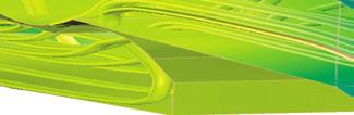
8 A Thorough Example: The Busbar This example familiarizes you with the COMSOL model object and the COMSOL API syntax. In this section, learn how to: Create a geometry Set up a mesh and apply physics properties Solve the problem Generate results for analysis Exchange the model between the scripting interface of MATLAB and the COMSOL desktop. The model you are building at the MATLAB command line is the same model described in the Introduction to COMSOL Multiphysics. The difference is that in that guide it is set up using the COMSOL Desktop instead of the COMSOL model object. This multiphysics example describes electrical heating in a busbar. The busbar is used to conduct a direct current from a transformer to an electric device, which is made of copper with titanium bolts, as shown in the figure below. Titanium Bolt 2a Titanium Bolt 2b Titanium Bolt 1 ABOUT COMPACT NOTATION This example uses compact notation to shorten the commands to be entered at the MATLAB command line. The compact notation uses MATLAB variables as links to provide direct access to COMSOL model object features. 8 A Thorough Example: The Busbar
9 For example, to create a block using the compact notation, enter: blk1 = geom1.feature.create('blk1', 'Block'); blk1.setindex('size', '2', 0); blk1.setindex('size', '3', 1); This creates a block, then changes its width to 2 and its depth to 3. Compared to above, the commands using a full notation are: geom1.feature.create('blk1', 'Block'); geom1.feature('blk1').setindex('size', '2', 0); geom1.feature('blk1').setindex('size', '3', 1); When a model object is saved in the M-file format the full notation is always used. Note: 'blk1'(with quotes) is the block geometry tag defined inside the COMSOL model object. The variable blk1 (without quotes), defined only in MATLAB, is the link to the block feature. By linking MATLAB variables to features you can directly access and modify features of the COMSOL model object in an efficient manner. ABOUT THE MODEL OBJECT The model object contains all the information about a model, from the geometry to the results. The model object is defined on the COMSOL server and can be accessed at the MATLAB command line using a link in MATLAB. 1 Start COMSOL with MATLAB as in the section Starting COMSOL with MATLAB. 2 Start modeling by creating a model object on the COMSOL server: model = ModelUtil.create('Model'); The model object on the COMSOL server has the tag Model while the variable model is its link in MATLAB. To access and modify the model object the LiveLink interface uses the COMSOL API syntax. 3 Set a name for the model object: model.name('busbar'); The name defined by the name method is intended only for visualization purposes when exporting the model to the COMSOL Desktop. A Thorough Example: The Busbar 9
10 ABOUT GLOBAL PARAMETERS If you plan to solve your problem for several different parameter values, it is convenient to define them in the Parameters node, and to take advantage of the COMSOL parametric sweep functionality. Global parameters can be used in expressions during all stages of the model set-up, for example, when creating geometry, applying physics, or defining the mesh. 1 Define the parameters for the busbar model: model.param.set('l', '9[cm]', 'Length of the busbar'); model.param.set('rad_1', '6[mm]', 'Radius of the fillet'); model.param.set('tbb', '5[mm]', 'Thickness'); model.param.set('wbb', '5[cm]', 'Width'); model.param.set('mh', '6[mm]', 'Maximum element size'); model.param.set('htc', '5[W/m^2/K]', 'Heat transfer coefficient'); model.param.set('vtot', '20[mV]', 'Applied electric potential'); GEOMETRY 1 Create a 3D geometry node: geom1 = model.geom.create('geom1', 3); The create method of the geometry node requires as input a tag for the geometry name ('geom1'), and the geometry space dimension (3 for 3D). 2 The initial geometry is obtained by extruding a 2D drawing. Create a work plane tagged 'wp1', and set it as the xz-plane of the 3D geometry: wp1 = geom1.feature.create('wp1', 'WorkPlane'); wp1.set('quickplane', 'xz'); 3 In this work plane, create a rectangle and set the width to L+2*tbb and the height to 0.1: r1 = wp1.geom.feature.create('r1', 'Rectangle'); r1.set('size', {'L+2*tbb' '0.1'}); Note: When the size properties of the rectangle are enclosed with single quotes ' ', it indicates that the variables L and tbb are defined within the model object. In this case they are defined in the Parameters node. 4 Create a second rectangle and set the width to L+tbb and the height to 0.1-tbb. Then change the rectangle position to (0;tbb): r2 = wp1.geom.feature.create('r2', 'Rectangle'); r2.set('size', {'L+tbb' '0.1-tbb'}); r2.set('pos', {'0' 'tbb'}); 10 A Thorough Example: The Busbar
.set({'r1'}); dif1.selection('input2').set({'r2'}); Display the current geometry using mphgeom.")
11 5 Subtract rectangle r2 from rectangle r1, by creating a Difference feature with the 'input' property set to r1 and the 'input2' property set to r2: dif1 = wp1.geom.feature.create('dif1', 'Difference'); dif1.selection('input').set({'r1'}); dif1.selection('input2').set({'r2'}); Display the current geometry using mphgeom. Enter at the MATLAB prompt: mphgeom(model,'geom1'); 6 Round the inner corner by creating a Fillet feature and set point 3 in the selection property. Then set the radius to tbb: fil1 = wp1.geom.feature.create('fil1', 'Fillet'); fil1.selection('point').set('dif1(1)', 3); fil1.set('radius', 'tbb'); 7 Round the outer corner by creating a new Fillet feature, then select point 6 and set the radius to 2*tbb: fil2 = wp1.geom.feature.create('fil2', 'Fillet'); fil2.selection('point').set('fil1(1)', 6); fil2.set('radius', '2*tbb'); For geometry operations the name of the resulting geometry objects is formed by appending a numeral in parenthesis to the tag of the geometry operation. Above, 'fil1(1)' is the result of the 'fil1' operation. 8 Extrude the geometry objects in the work plane. Create an Extrude feature, set the work plane wp1 as input and the distance to wbb: ext1 = geom1.feature.create('ext1', 'Extrude'); ext1.selection('input').set({'wp1'}); ext1.set('distance', {'wbb'}); A Thorough Example: The Busbar 11
. 9 Create a new work plane and set the planetype property to faceparallel.")
12 You can plot the current geometry by entering the following command at the MATLAB prompt: mphgeom(model) The busbar shape is now generated. Next create the cylinder that represent the bolts connecting the busbar to the external frame (not represented in the model). 9 Create a new work plane and set the planetype property to faceparallel. Then set the selection to boundary 8: wp2 = geom1.feature.create('wp2', 'WorkPlane'); wp2.set('planetype', 'faceparallel'); wp2.selection('face').set('ext1(1)', 8); 10 Create a circle and set the radius to rad_1: c1 = wp2.geom.feature.create('c1', 'Circle'); c1.set('r', 'rad_1'); 11 Create an Extrude node, select the second work plane wp2 as input, and then set the extrusion distance to -2*tbb: ext2 = geom1.feature.create('ext2', 'Extrude'); ext2.selection('input').set({'wp2'}); ext2.set('distance', {'-2*tbb'}); 12 Create a new workplane, set planetype to faceparallel, then set the selection to boundary 4: wp3 = geom1.feature.create('wp3', 'WorkPlane'); wp3.set('planetype', 'faceparallel'); wp3.selection('face').set('ext1(1)', 4); 13 Create a circle, then set the radius to rad_1 and set the position of the center to (-L/ 2+1.5e-2;-wbb/4): 12 A Thorough Example: The Busbar
13 c2 = wp3.geom.feature.create('c2', 'Circle'); c2.set('r', 'rad_1'); c2.set('pos', {'-L/2+1.5e-2' '-wbb/4'}); 14 Create a second circle in the work plane by copying the previous circle and displacing it a distance wbb/2 in the y-direction: copy1 = wp3.geom.feature.create('copy1', 'Copy'); copy1.selection('input').set({'c2'}); copy1.set('disply', 'wbb/2'); 15 Extrude the circles c2 and copy1 from the work plane wp3 a distance -2*tbb: ext3 = geom1.feature.create('ext3', 'Extrude'); ext3.selection('input').set({'wp3.c2' 'wp3.copy1'}); ext3.set('distance', {'-2*tbb'}); 16 Build the entire geometry sequence, including the finalize node using the run method: geom1.run; Note: The run method only builds features which need re-building or have not yet been built, including the finalize node. 17 Display the geometry with the mphgeom command: mphgeom(model) A Thorough Example: The Busbar 13
14 SELECTIONS You can create selections of geometric entities such as domains, boundaries, edges, or points. These selections can be accessed during the modeling process with the advantage of not having to select the same entities several times. 1 To create a domain selection corresponding to the titanium bolts, named Ti bolts enter: sel1 = model.selection.create('sel1'); sel1.set([ ]); sel1.name('ti bolts'); MATERIAL PROPERTIES The Material node of the model object stores the material properties. In this example the Joule Heating interface is used to involve both an electric current and a heat balance. Thus, the electrical conductivity, the heat capacity, the relative permittivity, the density, and the thermal conductivity of the materials all need to be defined. The busbar is made of copper and the bolts are made of titanium. The properties you need for these two materials are listed in the table below: PROPERTY COPPER TITANIUM Electrical conductivity 5.998e7[S/m] 7.407e5[S/m] Heat capacity 385[J/(kg*K)] 710[J/(kg*K)] Relative permittivity 1 1 Density 8700[kg/m^3] 4940[kg/m^3] Thermal conductivity 400[W/(m*K)] 7.5[W/(m*K)] 1 Create the first material, copper: mat1 = model.material.create('mat1'); 2 Set the properties for the 'electricconductivity', 'heatcapacity', 'relpermittivity', 'density' and 'thermalconductivity' according to the table above: mat1.materialmodel('def').set('electricconductivity', {'5.998e7[S/m]'}); mat1.materialmodel('def').set('heatcapacity', '385[J/(kg*K)]'); mat1.materialmodel('def').set('relpermittivity', {'1'}); mat1.materialmodel('def').set('density', '8700[kg/m^3]'); mat1.materialmodel('def').set('thermalconductivity', {'400[W/(m*K)]'}); 14 A Thorough Example: The Busbar
15 3 Set the name of the material to 'Copper'. By default the first material is assigned to all domains: mat1.name('copper'); 4 Create a second material using the material properties for titanium, and set its name to 'Titanium' : mat2 = model.material.create('mat2'); mat2.materialmodel('def').set('electricconductivity', {'7.407e5[S/m]'}); mat2.materialmodel('def').set('heatcapacity', '710[J/(kg*K)]'); mat2.materialmodel('def').set('relpermittivity', {'1'}); mat2.materialmodel('def').set('density', '4940[kg/m^3]'); mat2.materialmodel('def').set('thermalconductivity', {'7.5[W/(m*K)]'}); mat2.name('titanium'); 5 Assign the material to the selection 'sel1' (corresponding to the bolt domains) created previously: mat2.selection.named('sel1'); Only one material per domain can be assigned. This means that the last operation automatically removes the bolts from the selection of the copper material. PHYSICS INTERFACE The Physics node contains the settings of the physics interfaces, including the domain and the boundary settings. Settings are grouped together according to the physics interface they belong to. To model the electrothermal interaction of this example, add the JouleHeating interface to the model. Apply a fixed electric potential to the upper bolt and ground the two lower bolts. In addition, assume that the device is cooled by convection, approximated by a heat flux with a defined heat transfer coefficient on all outer faces except where the bolts are connected. 1 Create the JouleHeating interface on the geom1 geometry: jh = model.physics.create('jh', 'JouleHeating', 'geom1'); 2 Create a heat flux boundary condition and set the type to InwardHeatFlux: hf1 = jh.feature.create('hf1', 'HeatFluxBoundary', 2); Note: The third argument of the create method, the space dimension sdim, indicates at which geometry level (domain, boundary, edge, or point) the feature should be applied to. In the above commands 'HeatFluxBoundary' feature applies to boundaries, which have the space dimension 2. A Thorough Example: The Busbar 15
16 3 Now apply the cooling to all exterior boundaries 1 to 43 except the bolt connection boundaries 8, 15, and 43. An InwardHeatFlux boundary condition requires a heat transfer coefficient. Set its value to the previously defined parameter htc: hf1.set('heatfluxtype', 'InwardHeatFlux'); hf1.selection.set([1:7 9:14 16:42]); hf1.set('h', 'htc'); 4 As you have noticed, defining selections requires you to know the entity indices. To view the boundary indices, display the geometry with the face labels: mphgeom(model,'geom1','facemode','off','facelabels','on') You can use the controls in the window to zoom and pan to read off the indices. Note: Alternative methods for obtaining entity indices are described in the LiveLink for MATLAB User Guide. These include the use of point coordinates, selection boxes, or adjacency information. 5 Create an electric potential boundary condition; set the selection to boundary 43; then set the electric potential to Vtot: pot1 = jh.feature.create('pot1', 'ElectricPotential', 2); pot1.selection.set([43]); pot1.set('v0', 'Vtot'); 6 Apply a ground boundary condition to boundaries 8 and 15: gnd1 = jh.feature.create('gnd1', 'Ground', 2); gnd1.selection.set([8 15]); The model object includes default properties so you do not need to set properties for all boundaries. For example, the Joule heating physics interface uses a current insulation as default boundary condition for the current balance. MESH The mesh sequence is stored in the Mesh node. Several mesh sequences, also called mesh cases, can be created in the same model object. 1 Create a new mesh case for geom1: mesh1 = model.mesh.create('mesh1', 'geom1'); 16 A Thorough Example: The Busbar

17 2 By default the mesh sequence contains at least a size feature, which applies to all the subsequent meshing operations. First create a link to the existing size feature and then set the maximum element size hmax to mh and the minimum element size hmin to mh-mh/3. Then set the curvature factor hcurve to 0.2: size = mesh1.feature('size'); size.set('hmax', 'mh'); size.set('hmin', 'mh-mh/3'); size.set('hcurve', '0.2'); 3 Create a free tetrahedron mesh: ftet1 = mesh1.feature.create('ftet1', 'FreeTet'); 4 Build the mesh: mesh1.run; 5 Visualize the mesh in a MATLAB figure using the command mphmesh: mphmesh(model) STUDY In order to solve the model you need to create a Study node where the analysis type is set to be solved for. 1 Create a study node and add a stationary study step: std1 = model.study.create('std1'); stat = std1.feature.create('stat', 'Stationary'); 2 By default the progress bar for the solve and mesh operations is not displayed. To activate the progress bar enter: ModelUtil.showProgress(true) Once activated, the progress bar is displayed in a separate window during mesh or solver operations. The Progress window also contains log information. Note: The progress bar is not available on MAC OS X. A Thorough Example: The Busbar 17

18 3 Solve the model with the command: std1.run; During the computation a window opens to display the progress information and solver log. Note: In this example, no solver related settings were necessary since the study node automatically built the solver sequence based on the study type, physics interface, and the space dimension of the model. PLOTTING THE RESULTS Analyze the results by defining plot groups in the results node. To display the generated plots in a MATLAB figure use the mphplot command. 1 Create a 3D plot group: pg1 = model.result.create('pg1', 'PlotGroup3D'); 2 In the plot group, create a surface plot, activate a manual color range, set the minimum color value to 322.6, and se the maximum color value to 323: pg1.feature.create('surf1', 'Surface'); pg1.feature('surf1').set('rangecoloractive', 'on'); pg1.feature('surf1').set('rangecolormin', '322.6'); pg1.feature('surf1').set('rangecolormax', '323'); 3 To display the plot group including a color bar in a MATLAB figure: mphplot(model,'pg1','rangenum',1) 18 A Thorough Example: The Busbar

19 If several plot types are available in the same plot group, you can define which color bar to display. The value of the rangenum property corresponds to the plot type number in the plot group sequence. 4 Create a second plot group, with a surface plot type, and plot the norm of the current density. Set the maximum color range value to 1e6. Finally, add the title 'Current density norm (A/m^2)', display the plot in a MATLAB figure: pg2 = model.result.create('pg2', 'PlotGroup3D'); pg2.feature.create('surf1', 'Surface'); pg2.feature('surf1').set('expr', 'jh.normj'); pg2.feature('surf1').set('rangecoloractive', 'on'); pg2.feature('surf1').set('rangecolormax', '1e6'); pg2.set('title', 'Current density norm (A/m^2)'); mphplot(model,'pg2','rangenum',1); A Thorough Example: The Busbar 19
; data1.")
20 EXPORTING RESULTS Using the Export node results can be easily exported to a text file. 1 By entering the commands below, create a data export node to export the temperature variable T. Set the filename to <filepath>\temperature.txt where <filepath> is replaced with the path to the directory where the file should be saved. data1 = model.result.export.create('data1', 'Data'); data1.setindex('expr', 'T', 0); data1.set('filename','filepath\temperature.txt'); data1.run; The above steps extract the temperature at each computational node of the geometry and store the data in a text file in the following format: % Model: busbar.mph % Version: COMSOL % Date: Apr , 11:25 % Dimension: 3 % Nodes: 1787 % Expressions: 1 % Description: Temperature % x y z T (K) A Thorough Example: The Busbar
21 SAVING THE MODEL 1 To save the model using the save method enter: model.save('<path>/busbar'); In the above command, replace <path> with the directory where you would like to save your model. If a path is not defined, the model is saved automatically to the default COMSOL with MATLAB start-up directory. The default start-up directory on Windows and MAC OS X operating systems is usually [installdir]\comsol43\mli\startup, where [instaldir] is the path to the COMSOL installation directory, usually C:\ on Windows. On a computer running Linux, the start directory is the directory where the command comsol server matlab was issued. The default save format is the COMSOL binary format with the mph extension. To save the model as an M-file use the command: model.save('<path>/busbar','m'); LOADING THE MODEL TO THE COMSOL DESKTOP Use the COMSOL Desktop to open and examine the model just saved to the mph format. 1 Start COMSOL Multiphysics stand-alone. 2 From the File menu select Open, then browse to the mph file you have just saved and click Open. A Thorough Example: The Busbar 21
22 3 By expanding the nodes of the model tree in the Model Builder you can examine how the sequence of operations in the model correspond to the commands entered at the MATLAB command line. 22 A Thorough Example: The Busbar

23 Exchanging Models with the COMSOL Desktop While building the busbar model in MATLAB you have learned how to save a model as an MPH-file, which then can be opened from the COMSOL Desktop. From the COMSOL Desktop you can also directly transfer models to and from MATLAB. An additional way of transferring a model is in the M-file format. Because this format contains the commands for creating the model, rather than the model itself, you can use it as a starting point to create your own models in MATLAB. Note: On Linux you need to start COMSOL with MATLAB and the COMSOL desktop from the same terminal. Use the ampersand (&) command, for instance, comsol & or comsol server matlab &. TRANSFERRING A MODEL TO MATLAB As described in The COMSOL Client Server, models created in MATLAB exist on the COMSOL server, which can be either a local or remote server. To transfer a model to MATLAB, export it from the COMSOL Desktop to the COMSOL server and then create a link to the model in the MATLAB workspace. 1 If it is not already open, start a new COMSOL Desktop. Choose View>Model Library. In the Model Library window, choose COMSOL Multiphysics>Multiphysics>busbar and click Open. 2 Start COMSOL with MATLAB (see Starting COMSOL with MATLAB ). 3 In the COMSOL Desktop, go to File>Client Server>Export Model to Server. 4 Confirm that the correct export information is used: - In the Server area, define the Server name and the Port number in the fields. The default server name is localhost, which indicates that the COMSOL server is on the same machine. Check the port number by looking at the first line of the text displayed in the COMSOL server window: Exchanging Models with the COMSOL Desktop 23
24 COMSOL 4.3 started listening on port The User area contains the user login information. The Username and Password fields are set by default based on settings in the user preferences, defined the first time a COMSOL server is started. - The Model area contains the Model field where the model object name can be defined to export it from the COMSOL server. For this example enter Busbar 5 Click OK. Now that the model object is stored in the COMSOL server, create a link in MATLAB to gain access to it. 6 Once the Export model to server window has closed, enter at the MATLAB command line: model = ModelUtil.model('Busbar'); Busbar is the model object name, which was defined in step 4 above. 7 All features of the model can now be accessed, for example, plot the second plot group in a MATLAB figure: mphplot(model,'pg2','rangenum',1) 8 The model can also be modified, for example, by removing the second plot group from the results node: model.result.remove('pg2'); TRANSFERRING A MODEL TO THE COMSOL DESKTOP As well as transferring your model to MATLAB, the model edited at the MATLAB command line can be transferred to the COMSOL server. It only requires to load the model object from the COMSOL server to the COMSOL Desktop. 1 Start COMSOL with MATLAB and a COMSOL Desktop. 2 Create a model object, then create a 3D geometry and draw a block: model = ModelUtil.create('ImportExample'); model.geom.create('geom1', 3); 24 Exchanging Models with the COMSOL Desktop

25 model.geom('geom1').feature.create('blk1', 'Block'); model.geom('geom1').run; 3 In the COMSOL Desktop go to File>Client Server>Import Model from Server. 4 Make sure the following settings are correct: - In the Server area, define the Server name and the Port number in the fields. The default server name is localhost, which indicates that the COMSOL server is on the same machine. The port number is defined when starting the COMSOL server. The port number is displayed in the COMSOL server window In the above figure, the port number to use is The User area contains the user login information. The Username and Password fields are set by default based on settings in the user preferences, defined the first time a COMSOL server is started. - The Model area contains the Model field where the model object name can be defined to import from the COMSOL server. To get a list of available model objects on the COMSOL server enter at the MATLAB prompt: ModelUtil.tags which for this example returns the following: java.lang.string[]: 'ImportExample' Exchanging Models with the COMSOL Desktop 25

26 5 Click OK. Note: It is important to remember that if modifications are made to the model in the COMSOL Desktop, the model needs to be transferred back to MATLAB (the COMSOL server). SAVING AND RUNNING A MODEL M-FILE The easiest way to learn the commands of the COMSOL API is to save a model from the COMSOL Desktop as an M-file. The M-file contains the sequence of commands that create the model. You can open the M-file in a text editor and do modifications to it, as shown in the following example. Note: By default the M-file contains the entire command history of the model, including settings that are no longer part of the model. In order to include only settings that are part of the current model, you need to reset the model history before saving the M-file. 1 Start COMSOL with MATLAB and a COMSOL Desktop. 2 In the COMSOL Desktop go to the Model Library page, or select View>Model Library. 3 In the Model Library window, expand the COMSOL Multiphysics folder and then the Multiphysics folder. Select the busbar model and click Open. 4 In the COMSOL Desktop, choose File>Reset History. 5 Go to File>Save As Model M-File, name it busbar and choose the directory to save it to. Click OK. 26 Exchanging Models with the COMSOL Desktop
; model.result('pg3').feature('surf1').set('rangecolormax','1e6') The commands above define the plot group pg2.")
27 6 Open the saved M-file with the MATLAB editor or any text editor and scroll to lines : model.result('pg3').feature('surf1').set('expr','jh.normj'); model.result('pg3').feature('surf1').set('rangecolormax','1e6') The commands above define the plot group pg2. According to line 184 it includes a surface plot of the expression to jh.normj. On line 188 the maximum color range is set to 1e6. 7 Modify the plot group pg2 so that it displays the total heat jh.qtot and set the maximum color range to 1e4 instead. Starting on a new line right after line 188, append the following to the M-file: model.result('pg2').feature('surf1').set('expr','jh.qtot'); model.result('pg2').feature('surf1').set('rangecolormax','1e4'); These commands are executed after lines and modify plot group pg2 so that it displays the total heat jh.qtot with a new setting for the maximum value for the color range. Line 184 and 188 can also be modified to achieve the same thing, but this way you can easily revert to the old version. 8 Save the modified M-file. 9 Run the model at the MATLAB prompt with the command: model = busbar; 10 Display the plot group pg2: mphplot(model,'pg2','rangenum',1) Another way to modify a model object in MATLAB is to export the model from the COMSOL Desktop to MATLAB (see Transferring a Model to MATLAB ) and then enter the commands in step 5 directly at the MATLAB command line. The benefit of this latter approach is that it does not require running the entire model. See An Example Using Multiple for Loops, where this technique is applied. Exchanging Models with the COMSOL Desktop 27
28 Extracting Results at the MATLAB Command Line LiveLink for MATLAB packages several functions to make it easy to access results directly from the MATLAB command line. These functions are: mpheval, to evaluate expressions on all node points of a given domain selection, mphinterp, to evaluate expressions at extracts data arbitrary location, mphglobal, to evaluate global expressions, mphint, to integrate value of expressions on selected domains. Load the model busbar from the Model library directly at the MATLAB command line. 1 Start COMSOL with MATLAB. 2 Load the busbar example model from the Model Library. Enter the command: model = mphload('busbar'); The mphload command automatically searches the COMSOL path to find the requested file. You can also specify the path in the file name. EVALUATING DATA AT NODE POINTS Use the mpheval function to evaluate the electric potential, which is one of the busbar model dependent variables. mpheval returns the value of the expression evaluated using the nodes of a simplex mesh. By default the simplex mesh corresponds to the active mesh in the model object. 1 Enter at the command line: data = mpheval(model,'v') A MATLAB structure is returned according to: data = expr: {'V'} d1: [1x1787 double] p: [3x1787 double] t: [4x6416 int32] ve: [1787x1 int32] unit: {'V'} 28 Extracting Results at the MATLAB Command Line
29 mpheval returns a MATLAB structure defined with the following fields: - expr contains the list of the evaluated expression, - d1 contains the data of the evaluated expression, - p contains the coordinates of the evaluation points, - t contains the indices to columns in the p field. Each column in the t field corresponds to an element of the mesh used for the evaluation, - ve contains the indices of the mesh elements at each evaluation point, - unit contains the unit of the evaluated expression. 2 Multiple variables can be evaluated at once, for example both the temperature and the electric potential. Enter: data2 = mpheval(model,{'t' 'V'}) This command returns this structure: data2 = expr: {'T' 'V'} d1: [1x1787 double] d2: [1x1787 double] p: [3x1787 double] t: [4x6416 int32] ve: [1787x1 int32] unit: {'K' 'V'} The fields data2.d1 and data2.d2 contain the values for the temperature and electric potential, respectively. 3 Now evaluate the temperature T including at the element mid-points as defined by a quadratic shape function. Use the refine property and set the property value to 2, which corresponds to the discretization order: data3 = mpheval(model,{'t'},'refine',2) This command returns this structure: data3 = expr: {'T'} d1: [1x11304 double] p: [3x11304 double] t: [4x51328 int32] ve: [11304x1 int32] unit: {'K'} 4 This step tests how to use the edim property in combination with the selection property. edim allows you to determine the space dimension of the evaluation and selection allows you to set the entity number where to evaluate the expression. Evaluate data on a specific domain, for example the normal current density at boundary number 43: Extracting Results at the MATLAB Command Line 29
30 data4 = mpheval(model,{'jh.normj'},... 'edim',2,'selection',43) This command returns this structure: data4 = expr: {'jh.normj'} d1: [1x36 double] p: [3x36 double] t: [3x54 int32] ve: [36x1 int32] unit: {'A/m^2'} EVALUATING DATA AT ARBITRARY POINTS If you want to get data at a specific location not necessarily defined by node points, use the command mphinterp to interpolate the results. The interpolation method uses the shape function of the elements. 1 To extract the total heat source at [5e-2;-2e-2;1e-3] enter: Qtot = mphinterp(model,'jh.qtot','coord',[5e-2;-2e-2;1e-3]) This returns: Qtot = e A grid of points can also be evaluated. Enter the following lines: x0=0:5e-2/4:5e-2; y0=0:-2.5e-2/4:-2.5e-2; z0=[0 5e-3]; [x,y,z]=meshgrid(x0,y0,z0); xx=[x(:),y(:),z(:)]'; Qtot = mphinterp(model,'jh.qh','coord',xx); 3 Reshape the variable Qtot for a better visualization: Qtot = reshape(qtot,length(x0),length(y0),length(z0)) This results in: Qtot(:,:,1) = 1.0e+005 * Qtot(:,:,2) = 1.0e+003 * 30 Extracting Results at the MATLAB Command Line
31 GLOBAL EVALUATION AND INTEGRATION To obtain the maximum value of an expression, create a maximum operator within the COMSOL model object and evaluate its value using the mphglobal function. 1 Create a maximum operator on domain 1: maxop1 = model.cpl.create('maxop1','maximum','geom1'); maxop1.selection.set(1); 2 To access the operator in the results node, update the solution: model.sol('sol1').updatesolution; 3 To evaluate the global expression defined by maxop1(t): maxt = mphglobal(model,'maxop1(t)') This returns the maximum temperature: maxt = To calculate the total heat produced in the busbar you can integrate the total heat source, using the command mphint. Enter: Q = mphint(model,'jh.qh','selection',1) The total heat is: Q = Evaluate the total current passing through boundary 43 and retrieve the unit of the integral: [I unit] = mphint(model,'jh.normj','edim',2,'selection',43) I= unit = 'A' Extracting Results at the MATLAB Command Line 31
32 Automating with MATLAB Scripts The LiveLink interface allows you to combine the MATLAB programing tools with the COMSOL model object. A benefit of this integration is to access results at the MATLAB workspace. Another benefit is that you can integrate COMSOL modeling commands into MATLAB scripts, taking full advantage of all available tools for controlling the flow of your code. This section explains how to do this efficiently by introducing MATLAB variables into your COMSOL model and updating only the affected parts of your model object. OBTAINING MODEL INFORMATION Modifying an existing model object requires you to know how the model is set up. Some functions help you to access this information so that you can add or remove a model feature or modify the value of an existing property. The function mphnavigator helps you to retrieve model object information. Calling mphnavigator at the MATLAB prompt displays a summary of the features and their properties for the model object available in the MATLAB workspace. 1 Start COMSOL with MATLAB. 1 Load the busbar example model: model=mphload('busbar'); 2 To access the model information, enter the following command at the MATLAB prompt: mphnavigator 32 Automating with MATLAB Scripts

33 In the mphnavigator graphical user interface the model features are listed under the Model Tree section. The nodes can be expanded to access the subfeatures. When selecting a feature from the Model Tree, its properties are listed under the Properties section. The Methods section lists the method available for the selected feature. Just above the Methods section, you can see the COMSOL API syntax that lead to the feature. You can copy the command to the clipboard and easily paste it at the MATLAB prompt just press the Copy button to copy the syntax. 3 In the Model Tree, expand the model feature nodes down to geom>geom1>wp1>r1 and select the node r1. 4 In the Properties section, you can see the that the lx property of the geometry feature r1 is set to L+2*tbb, this represent the length of the rectangle. The width of the rectangle, represented with the property ly is set to 0.1. Automating with MATLAB Scripts 33

34 UPDATING MODEL SETTINGS The COMSOL model object allows you to modify parameters, features, or feature properties, using the set method. Once a property value is updated, you can run the appropriate sequence, depending on where the changes where introduced into the model for example, the geometry or the mesh sequence. Running the solver sequence automatically runs all sequences where modified settings are detected. Starting with the busbar model described in A Thorough Example: The Busbar, this section modifies a parameter value and re-solves the model. For this purpose, the geometry of the model is prepared using parameters such as L, the length of the busbar, and tbb, the thickness of the busbar. 1 Start COMSOL with MATLAB (if you have not done so already). 2 Load the model from the COMSOL model library: model = mphload('busbar'); 3 Plot the current solution with this command: mphplot(model,'pg2','rangenum',1); 4 The first exercise changes the length of the parameters L (length of the busbar). Enter: model.param.set('l','18[cm]'); 5 To run the solver sequence and compute the solution enter: model.sol('sol1').run; 34 Automating with MATLAB Scripts

35 Note: The solver node automatically detects all modifications in the model, and runs the geometry or mesh sequences when needed. Here, the new value for the parameter L induces a change in the geometry and thus a new mesh is also needed. Full associativity is also ensured making sure that all physics settings remain applied as in the original model. 6 Plot the updated solution, which results in the geometry change: mphplot(model,'pg2','rangenum',1); USING MATLAB VARIABLES IN THE COMSOL MODEL Use the set method described in the previous section to define the feature properties using MATLAB variables. It is important to make sure that the value of the MATLAB variable is consistent with the units used in the model. Before beginning, make sure that the busbar model used in the previous section is loaded into MATLAB. First, change the length of the busbar, described by the parameter L. 1 Create a MATLAB variable L0 equal to 9e-2: L0 = 9e-2; 2 Update the value of the parameter L with the variable L0: model.param.set('l',l0); Automating with MATLAB Scripts 35
36 Note: In contrast to this command, setting a value using an expression from within the model object requires the second argument to be a string expression, as shown in Updating Model Settings. 3 Re-run the geometry sequence to update the geometry: model.geom('geom1').run; 4 To display the new geometry enter: mphgeom(model,'geom1') Working with parameters is convenient, since there is one place where you need to go to view or modify the current configuration of the model. The next step uses a different method, where a feature node is edited to modify its properties. For example, to modify the busbar geometry. the rectangles r1 and r2 generated in the work plane wp1 are edited. 5 Start to create links to the geometry feature r1 and r2 by entering the commands: r1 = model.geom('geom1').feature('wp1').geom.feature('r1'); r2 = model.geom('geom1').feature('wp1').geom.feature('r2'); 6 Enter the following command to define MATLAB variables: H1 = 0.2; H2 = 0.195; 7 Set the height of rectangles r1 and r2 using the variables H1 and H2, respectively. r1.set('ly', H1); r2.set('ly', H2); Note: The function mphproperties can be used to get a list of properties and values for feature nodes of a model. See Obtaining Model Information for more details. 36 Automating with MATLAB Scripts
; There is a third option when defining property values for features: to combine MATLAB variables with parameters or variables")
37 8 To update the geometry, enter: model.geom('geom1').run; 9 Enter this command to plot the geometry: mphgeom(model,'geom1'); There is a third option when defining property values for features: to combine MATLAB variables with parameters or variables defined within the COMSOL model object. To do this the MATLAB variable just needs to be converted to a string. This last exercise tests this by changing the height of rectangle r1 and r2 to L0, and L0-tbb, respectively, where L0 is a MATLAB variable. 10 Define the variable L0: L0 = 0.1; 11 Modify the ly property of rectangles r1 and r2: r1.set('ly',l0) r2.set('ly',[num2str(l0) '-tbb']); Automating with MATLAB Scripts 37
38 12 Update and plot the geometry: model.geom('geom1').run; mphgeom(model,'geom1'); AN EXAMPLE USING MULTIPLE FOR LOOPS In this example, a MATLAB function is created that solves the busbar model for different values of the length and thickness of the busbar, and the input electric potential. The function evaluates and returns the maximum temperature in the busbar, the generated heat, and the current through the busbar. For each variation of the model the function stores these results in a file and saves the model object in a MPH file. To make it easy to identify the name of the MPH-file, it contains the values of the different parameters used to set-up the model. The input argument of the M-function is the busbar model object and the path to the directory where the data and models are saved. 1 Open a text editor, for example the MATLAB text editor. 2 At the first line of a new M-file, enter the following function header: function modelparam(model,filepath) The function first creates a file and then sets the header of the output file format. 38 Automating with MATLAB Scripts
39 3 In the text editor continue to enter the following lines: filename = fullfile(filepath,'results.txt'); fid=fopen(filename,'wt'); fprintf(fid,'*** run parametric study ***\n'); fprintf(fid,'l[m] tbb[m] Vtot[V] '); fprintf(fid,'maxt[k] TotQ[W] Current[A]\n'); 4 In order to evaluate the maximum values add a coupling operator to the model. Enter the lines: maxop1 = model.cpl.create('maxop1','maximum','geom1'); maxop1.selection.set(1); 5 When running a large amount of iteration, the model history can be disabled to prevent the memory from rising along the iterations due to the model history stored in the model. Enter the lines: model.hist.disable; 6 Now start a for loop to parameterize the parameter L and set the corresponding parameter in the model object. Enter the commands: for L = [9e-2 15e-2] model.param.set('l',l); 7 Continue by creating a second for loop, this time to parameterize the parameter tbb and to modify its value in the model object: for tbb = [5e-3 10e-3] model.param.set('tbb',tbb); 8 Define the last for loop to parameterize the applied potential Vtot: for Vtot = [20e-3 40e-3] model.param.set('vtot',vtot); 9 For each version of the model write the parameter values to the output file: fprintf(fid,[num2str(l),' ',num2str(tbb),... ' ',num2str(vtot),' ']); 10 To solve the model, add the line below: model.sol('sol1').run; 11 The following lines evaluate the results: MaxT = mphglobal(model,'maxop1(t)'); TotQ = mphint(model,'jh.qtot','selection',1); Current = mphint(model,'jh.normj',... 'edim',2,'selection',43); 12 Save the results to the output text file: fprintf(fid,[num2str(maxt),' ',num2str(totq),... ' ',num2str(current),' \n']); Automating with MATLAB Scripts 39
40 13 Name and save the model: modelname = fullfile(filepath,['busbar_l=',num2str(l),... '_tbb=',num2str(tbb),... '_Vtot=',num2str(Vtot),'.mph']); model.save(modelname); 14 Terminate the for loops: end end end 15 Close the output text file: fclose(fid); The script in the text editor should now look like this text: function modelparam(model,filepath) filename = fullfile(filepath,'results.txt'); fid=fopen(filename,'wt'); fprintf(fid,'*** run parametric study ***\n'); fprintf(fid,'l[m] tbb[m] Vtot[V] '); fprintf(fid,'maxt[k] TotQ[W] Current[A]\n'); maxop1 = model.cpl.create('maxop1','maximum','geom1'); maxop1.selection.set(1); model.hist.disable; for L = [9e-2 15e-2] model.param.set('l',l); for tbb = [5e-3 10e-3] model.param.set('tbb',tbb); for Vtot = [20e-3 40e-3] model.param.set('vtot',vtot); fprintf(fid,[num2str(l),' ',num2str(tbb),... ' ',num2str(vtot),' ']); model.sol('sol1').run; MaxT = mphglobal(model,'maxop1(t)'); TotQ = mphint(model,'jh.qtot','selection',1); Current = mphint(model,'jh.normj',... 'edim',2,'selection',43); fprintf(fid,[num2str(maxt),' ',num2str(totq),... ' ',num2str(current),' \n']); modelname = fullfile(filepath,['busbar_l=',num2str(l),... '_tbb=',num2str(tbb),... '_Vtot=',num2str(Vtot),'.mph']); model.save(modelname); end end end fclose(fid); 16 Save the M-file as modelparam.m in a directory known by MATLAB. 40 Automating with MATLAB Scripts
41 17 If COMSOL with MATLAB is not already running, start it now and load the model busbar from the Model library: model = mphload('busbar'); 18 Run the function, substitute 'filepath' to a directory of your choice: modelparam(model,'filepath') 19 Open the file results.txt in a text editor to look at the summary of the results: *** run parametric study *** L[m] tbb[m] Vtot[V] MaxT[K] TotQ[W] Current[A] Although this example duplicates functionality that is readily accessible in the COMSOL Desktop, you can, by using a similar technique, couple a COMSOL model to your customized optimization script. Automating with MATLAB Scripts 41
42 Using External MATLAB Functions Another advantage of using LiveLink for MATLAB is the ability to call a MATLAB function directly from within the COMSOL Desktop. You can use the function to define, within the COMSOL model object, properties such as material definitions or physics settings. COMSOL automatically detects the external function and starts the MATLAB engine to evaluate it. The function output is then applied to the corresponding property. To use this functionality, just start the COMSOL Desktop and MATLAB automatically starts in the background when needed. Note: On Linux operating systems, specify the MATLAB root directory path MLROOT and load the gcc library when starting the COMSOL Desktop: comsol -mlroot MLROOT -forcegcc. The example in this section illustrates how to use external MATLAB functions in a COMSOL model. The model computes for the temperature distribution in a material subjected to an external heat flux. Both the thermal conductivity of the material and the applied heat flux are defined by MATLAB functions. CREATING THE MATLAB FUNCTIONS Assume that the material in the example is characterized by a random thermal conductivity. To define the thermal conductivity, create a MATLAB function with the location along the x-axis as an input argument and let the conductivity vary randomly within 200 W/(m*K) around a constant value of 400 W/(m*K). Define a second MATLAB function for the external heat flux to be a function of the following arguments: x and y, the location coordinates. x0 and y0, the coordinates of the center of application of the heat source. Q0, the maximum heat source. scale, a parameter that scale the period of the heat flux. x and y are dependent variables of the model. x0, y0, Q0, and scale are defined with constant value in this exercise. 42 Using External MATLAB Functions
43 1 Open a text editor, for example the MATLAB text editor. 2 In a new file enter: function out=conductivity(x) out = 400+5*randn(size(x)); 3 Save the file as conductivity.m. 4 Create a new file and enter: function out = heatflux(x,y,x0,y0,q0,scale) radius = sqrt((x-x0).^2+(y-y0).^2); out = Q0/5+Q0/2.*sin(scale*pi.*radius)./(scale*pi.*radius); 5 Save the file as HeatFlux.m. Note: For both functions the input arguments have the size of the space coordinate variables x and y. These variables are defined as arrays, and the function needs to return an array with the same size as the input arguments. Ensure that this is the case by using the size command and pointwise operators (.* and./). MODEL WIZARD 1 Start COMSOL Multiphysics. 2 In the Model Wizard window, on the Select Space Dimension page, select 3D. Click Next. 3 On the Add Physics page, select Heat Transfer > Heat Transfer in Solids(ht). Click Next. 4 On the Select Study Type page, under Preset Studies select Stationary. 5 Click Finish. DEFINING THE EXTERNAL MATLAB FUNCTIONS IN THE MODEL You have noticed that the two MATLAB functions are highlighted in orange after being entered. This is because they need to be defined in the model before COMSOL can recognize them as external MATLAB functions. Using External MATLAB Functions 43


44 1 Right-click Global Definitions node and select Functions > MATLAB. 2 On the Settings page, under the Functions section in the Function field enter conductivity and under the Arguments field enter x. By defining the function here, COMSOL knows that conductivity is a MATLAB function. COMSOL automatically starts MATLAB to evaluate the function when necessary. Note: Saving the COMSOL model at the location (as for the external MATLAB functions) ensures that the functions path is known by MATLAB. Other alternatives consist in setting the function path directly in MATLAB before running the model or setting the environment variable COMSOL_MATLAB_PATH with the directory path of the functions. 3 Go to the File menu, select Save As, and browse to the directory where the files conductivity.m and heatflux.m are stored. You can display the value of the function defined by first defining the plot limit for the input arguments. 4 Expand the Plot parameters section. In the associated table enter 0 as Lower limit and 1 as Upper limit. 44 Using External MATLAB Functions


45 5 Click the Plot button. You can now define a second MATLAB function that returns the heat flux condition. 6 Repeating the above procedure, add a new MATLAB function. On the Settings page under Functions section, enter heatflux in the Function field and set the Arguments field with x,y,x0,y0,scale. 7 To display the function enter the following in the Plot parameters table: LOWER LIMIT UPPER LIMIT Using External MATLAB Functions 45

, the expression of Density")
46 LOWER LIMIT UPPER LIMIT 1e4 1e Click the Plot button. GEOMETRY AND MATERIAL DEFINITION 1 Right-click the Geometry 1 node and select Block. 2 Click Build All. 3 Right-click the Materials node and select Material. 4 Under Material Contents, in the Value column set the expression of the Thermal conductivity to conductivity(x), the expression of Density to 8e3 and the expression of Heat Capacity at Constant Pressure to 2e3. Note: The expression conductivity(x) displays in orange as the MATLAB function is unitless. 46 Using External MATLAB Functions
.")
47 HEAT TRANSFER IN SOLIDS 1 Add a constant temperature boundary condition. Right-click Heat Transfer in Solids, then select Temperature. 2 On the Temperature settings page, select boundaries 3, 5, and 6 (You can also use the Paste Selection button to enter directly the selection). 3 To add a boundary heat flux right-click Heat Transfer in Solids node, and select Heat Flux. 4 On the Heat flux settings page select boundary 4 and set the General inward heat flux expression to heatflux(x,y,0.5,0.5,1e4,3). COMPUTING AND PLOTTING THE RESULTS Once the model is set-up the solution can be computed. A default mesh is automatically generated. 1 Right-click the Study node and select Compute. 2 Click the Temperature (ht) node to display the temperature field at the geometry surface. Using External MATLAB Functions 47


48 3 Visualize the material thermal conductivity in the geometry by adding a new 3D Plot group in the Results node. Then right-click 3D Plot group 3 node and select Isosurface. 4 On the associated Settings page, under the Expression section, enter conductivity(x) in the Expression field. 5 Under Levels section change the Total levels to Click the Plot button. 48 Using External MATLAB Functions
LiveLink. for Matlab. User s Guide VERSION 4.4
 TM LiveLink for Matlab User s Guide VERSION 4.4 LiveLink for MATLAB User s Guide 2009 2013 COMSOL Protected by U.S. Patents 7,519,518; 7,596,474; 7,623,991; and 8,457,932. Patents pending. This Documentation
VERSION 4.3. Quick Installation Guide
 VERSION 4.3 Quick Installation Guide COMSOL Multiphysics Quick Installation Guide 1998 2012 COMSOL Protected by U.S. Patents 7,519,518; 7,596,474; and 7,623,991. Patents pending. This Documentation and
Introduction to Comsol Multiphysics
 Introduction to Comsol Multiphysics VERSION 4.3 Introduction to COMSOL Multiphysics 1998 2012 COMSOL Protected by U.S. Patents 7,519,518; 7,596,474; and 7,623,991. Patents pending. This Documentation and
Outline. COMSOL Multyphysics: Overview of software package and capabilities
 COMSOL Multyphysics: Overview of software package and capabilities Lecture 5 Special Topics: Device Modeling Outline Basic concepts and modeling paradigm Overview of capabilities Steps in setting-up a
Automation of COMSOL Multiphysics Parameter Studies using the MATLAB LiveLink
 Automation of COMSOL Multiphysics Parameter Studies using the MATLAB LiveLink Dominik Kern a, Nils-Henning Framke b September 26, 2012 Abstract COMSOL Multiphysics is a Finite Element Methods (FEM) software
Creating a 2D Geometry Model
 Creating a 2D Geometry Model This section describes how to build a 2D cross section of a heat sink and introduces 2D geometry operations in COMSOL. At this time, you do not model the physics that describe
INTRODUCTION TO Application Builder
 INTRODUCTION TO Application Builder Introduction to Application Builder 1998 2017 COMSOL Protected by patents listed on www.comsol.com/patents, and U.S. Patents 7,519,518; 7,596,474; 7,623,991; 8,457,932;
INTRODUCTION TO Application Builder
 INTRODUCTION TO Application Builder Introduction to Application Builder 1998 2017 COMSOL Protected by patents listed on www.comsol.com/patents, and U.S. Patents 7,519,518; 7,596,474; 7,623,991; 8,457,932;
VERSION 4.3. Introduction to Heat Transfer Module
 VERSION 4.3 Introduction to Heat Transfer Module Introduction to the Heat Transfer Module 1998 2012 COMSOL Protected by U.S. Patents 7,519,518; 7,596,474; and 7,623,991. Patents pending. This Documentation
Middle East Technical University Mechanical Engineering Department ME 413 Introduction to Finite Element Analysis Spring 2015 (Dr.
 Middle East Technical University Mechanical Engineering Department ME 413 Introduction to Finite Element Analysis Spring 2015 (Dr. Sert) COMSOL 1 Tutorial 2 Problem Definition Hot combustion gases of a
Introduction to comsol multiphysics. V ERSION 4.0a
 Introduction to comsol multiphysics V ERSION 4.0a Benelux COMSOL BV Röntgenlaan 19 2719 DX Zoetermeer The Netherlands Phone: +31 (0) 79 363 4230 Fax: +31 (0) 79 361 4212 info@comsol.nl www.comsol.nl Denmark
INTRODUCTION TO COMSOL Multiphysics
 INTRODUCTION TO COMSOL Multiphysics Introduction to COMSOL Multiphysics 1998 2017 COMSOL Protected by patents listed on www.comsol.com/patents, and U.S. Patents 7,519,518; 7,596,474; 7,623,991; 8,457,932;
VERSION 4.3. Introduction to Optimization Module
 VERSION 4.3 Introduction to Optimization Module Introduction to the Optimization Module 1998 2012 COMSOL Protected by U.S. Patents 7,519,518; 7,596,474; and 7,623,991. Patents pending. This Documentation
Implementation in COMSOL
 Implementation in COMSOL The transient Navier-Stoke equation will be solved in COMSOL. A text (.txt) file needs to be created that contains the velocity at the inlet of the common carotid (calculated as
For this week only, the TAs will be at the ACCEL facility, instead of their normal office hours.
 BEE 3500 Homework Assignment 5 Notes: For this assignment, you will use the computational software COMSOL Multiphysics 5.3, available in Academic Computing Center Engineering Library (ACCEL) at the Carpenter
INTRODUCTION TO COMSOL Multiphysics
 INTRODUCTION TO COMSOL Multiphysics Introduction to COMSOL Multiphysics 1998 2014 COMSOL Protected by U.S. Patents listed on www.comsol.com/patents, and U.S. Patents 7,519,518; 7,596,474; 7,623,991; and
Convection Cooling of Circuit Boards 3D Natural Convection
 Convection Cooling of Circuit Boards 3D Natural Convection Introduction This example models the air cooling of circuit boards populated with multiple integrated circuits (ICs), which act as heat sources.
Basic Exercises Maxwell Link with ANSYS Mechanical. Link between ANSYS Maxwell 3D and ANSYS Mechanical
 Link between ANSYS Maxwell 3D and ANSYS Mechanical This exercise describes how to set up a Maxwell 3D Eddy Current project and then link the losses to ANSYS Mechanical for a thermal calculation 3D Geometry:
INTRODUCTION TO COMSOL Multiphysics
 INTRODUCTION TO COMSOL Multiphysics Introduction to COMSOL Multiphysics 1998 2015 COMSOL Protected by U.S. Patents listed on www.comsol.com/patents, and U.S. Patents 7,519,518; 7,596,474; 7,623,991; 8,457,932;
An Example Eddy Currents
 An Example Eddy Currents Introduction To help you understand how to create models using the AC/DC Module, this section walks through an example in great detail. You can apply these techniques to all the
Autodesk Inventor 2019 and Engineering Graphics
 Autodesk Inventor 2019 and Engineering Graphics An Integrated Approach Randy H. Shih SDC PUBLICATIONS Better Textbooks. Lower Prices. www.sdcpublications.com Powered by TCPDF (www.tcpdf.org) Visit the
CST EM STUDIO 3D EM FOR STATICS AND LOW FREQUENCIES TUTORIALS
 CST EM STUDIO 3D EM FOR STATICS AND LOW FREQUENCIES TUTORIALS CST STUDIO SUITE 2006 Copyright 2002-2005 CST GmbH Computer Simulation Technology All rights reserved. Information in this document is subject
Lab 9: FLUENT: Transient Natural Convection Between Concentric Cylinders
 Lab 9: FLUENT: Transient Natural Convection Between Concentric Cylinders Objective: The objective of this laboratory is to introduce how to use FLUENT to solve both transient and natural convection problems.
Strömningslära Fluid Dynamics. Computer laboratories using COMSOL v4.4
 UMEÅ UNIVERSITY Department of Physics Claude Dion Olexii Iukhymenko May 15, 2015 Strömningslära Fluid Dynamics (5FY144) Computer laboratories using COMSOL v4.4!! Report requirements Computer labs must
Assignment in The Finite Element Method, 2017
 Assignment in The Finite Element Method, 2017 Division of Solid Mechanics The task is to write a finite element program and then use the program to analyse aspects of a surface mounted resistor. The problem
VERSION 4.4. Introduction to Pipe Flow Module
 VERSION 4.4 Introduction to Pipe Flow Module Introduction to the Pipe Flow Module 1998 2013 COMSOL Protected by U.S. Patents 7,519,518; 7,596,474; 7,623,991; and 8,457,932. Patents pending. This Documentation
Free Convection in a Water Glass
 Solved with COMSOL Multiphysics 4.1. Free Convection in a Water Glass Introduction This model treats free convection in a glass of water. Free convection is a phenomenon that is often disregarded in chemical
Non-Isothermal Heat Exchanger
 Non-Isothermal Heat Exchanger The following example builds and solves a conduction and convection heat transfer problem using the Heat Transfer interface. The example concerns a stainless-steel MEMS heat
Melting Using Element Death
 Melting Using Element Death Introduction This tutorial was completed using ANSYS 7.0 The purpose of the tutorial is to outline the steps required to use element death to model melting of a material. Element
Design a Simple Fan in 123D Design
 Design a Simple Fan in 123D Design Learn to use 123D Design to make and print this simple fan. 123D Design is a free, powerful, yet simple 3D creation and editing tool. It allows you to design and build
First Steps - Conjugate Heat Transfer
 COSMOSFloWorks 2004 Tutorial 2 First Steps - Conjugate Heat Transfer This First Steps - Conjugate Heat Transfer tutorial covers the basic steps to set up a flow analysis problem including conduction heat
Tutorial Second Level
 AutoCAD 2018 Tutorial Second Level 3D Modeling Randy H. Shih SDC PUBLICATIONS Better Textbooks. Lower Prices. www.sdcpublications.com Powered by TCPDF (www.tcpdf.org) Visit the following websites to learn
3D Design with 123D Design
 3D Design with 123D Design Introduction: 3D Design involves thinking and creating in 3 dimensions. x, y and z axis Working with 123D Design 123D Design is a 3D design software package from Autodesk. A
3. Preprocessing of ABAQUS/CAE
 3.1 Create new model database 3. Preprocessing of ABAQUS/CAE A finite element analysis in ABAQUS/CAE starts from create new model database in the toolbar. Then save it with a name user defined. To build
Autodesk Fusion 360: Model. Overview. Modeling techniques in Fusion 360
 Overview Modeling techniques in Fusion 360 Modeling in Fusion 360 is quite a different experience from how you would model in conventional history-based CAD software. Some users have expressed that it
ANSYS 5.6 Tutorials Lecture # 2 - Static Structural Analysis
 R50 ANSYS 5.6 Tutorials Lecture # 2 - Static Structural Analysis Example 1 Static Analysis of a Bracket 1. Problem Description: The objective of the problem is to demonstrate the basic ANSYS procedures
Exercise Guide. Published: August MecSoft Corpotation
 VisualCAD Exercise Guide Published: August 2018 MecSoft Corpotation Copyright 1998-2018 VisualCAD 2018 Exercise Guide by Mecsoft Corporation User Notes: Contents 2 Table of Contents About this Guide 4
SOLIDWORKS 2016 and Engineering Graphics
 SOLIDWORKS 2016 and Engineering Graphics An Integrated Approach Randy H. Shih SDC PUBLICATIONS Better Textbooks. Lower Prices. www.sdcpublications.com Powered by TCPDF (www.tcpdf.org) Visit the following
Practice to Informatics for Energy and Environment
 Practice to Informatics for Energy and Environment Part 3: Finite Elemente Method Example 1: 2-D Domain with Heat Conduction Tutorial by Cornell University https://confluence.cornell.edu/display/simulation/ansys+-+2d+steady+conduction
Laboratory Assignment: EM Numerical Modeling of a Stripline
 Laboratory Assignment: EM Numerical Modeling of a Stripline Names: Objective This laboratory experiment provides a hands-on tutorial for drafting up an electromagnetic structure (a stripline transmission
Autodesk Fusion 360 Training: The Future of Making Things Attendee Guide
 Autodesk Fusion 360 Training: The Future of Making Things Attendee Guide Abstract After completing this workshop, you will have a basic understanding of editing 3D models using Autodesk Fusion 360 TM to
Solved with COMSOL Multiphysics 4.3a
 Magnetic Lens Introduction Scanning electron microscopes image samples by scanning with a high-energy beam of electrons. The subsequent electron interactions produce signals such as secondary and back-scattered
Step 1: Problem Type Specification. (1) Open COMSOL Multiphysics 4.1. (2) Under Select Space Dimension tab, select 2D Axisymmetric.
 Open COMSOL Multiphysics 4.1. (2) Under Select Space Dimension tab, select 2D Axisymmetric.") Step 1: Problem Type Specification (1) Open COMSOL Multiphysics 4.1. (2) Under Select Space Dimension tab, select 2D Axisymmetric. (3) Click on blue arrow next to Select Space Dimension title. (4) Click
Step 1: Problem Type Specification (1) Open COMSOL Multiphysics 4.1. (2) Under Select Space Dimension tab, select 2D Axisymmetric. (3) Click on blue arrow next to Select Space Dimension title. (4) Click
Tutorial to simulate a thermoelectric module with heatsink in ANSYS
 Tutorial to simulate a thermoelectric module with heatsink in ANSYS Few details can be found in the pictures attached. All the material properties can be found in Dr. Lee s book and on the web. Don t blindly
3 AXIS STANDARD CAD. BobCAD-CAM Version 28 Training Workbook 3 Axis Standard CAD
 3 AXIS STANDARD CAD This tutorial explains how to create the CAD model for the Mill 3 Axis Standard demonstration file. The design process includes using the Shape Library and other wireframe functions
Structural & Thermal Analysis using the ANSYS Workbench Release 11.0 Environment. Kent L. Lawrence
 ANSYS Workbench Tutorial Structural & Thermal Analysis using the ANSYS Workbench Release 11.0 Environment Kent L. Lawrence Mechanical and Aerospace Engineering University of Texas at Arlington SDC PUBLICATIONS
Lesson 1 Parametric Modeling Fundamentals
 1-1 Lesson 1 Parametric Modeling Fundamentals Create Simple Parametric Models. Understand the Basic Parametric Modeling Process. Create and Profile Rough Sketches. Understand the "Shape before size" approach.
Solid Conduction Tutorial
 SECTION 1 1 SECTION 1 The following is a list of files that will be needed for this tutorial. They can be found in the Solid_Conduction folder. Exhaust-hanger.tdf Exhaust-hanger.ntl 1.0.1 Overview The
ANSYS EXERCISE ANSYS 5.6 Temperature Distribution in a Turbine Blade with Cooling Channels
 I. ANSYS EXERCISE ANSYS 5.6 Temperature Distribution in a Turbine Blade with Cooling Channels Copyright 2001-2005, John R. Baker John R. Baker; phone: 270-534-3114; email: jbaker@engr.uky.edu This exercise
Thermal Stress Analysis
 Thermal Stress Analysis Determine the temperature-induced stresses in a disk brake rotor. Lesson: Thermal Stress Analysis of a Disk Brake Rotor In this exercise we'll perform a Thermal Stress analysis
Problem description. Problem 65: Free convection in a lightbulb. Filament (Tungsten): Globe (Glass): = FSI boundary. Gas (Argon):
: Globe (Glass): = FSI boundary. Gas (Argon):") Problem description This tutorial demonstrates the use of ADINA for analyzing the fluid flow and heat transfer in a lightbulb using the Thermal Fluid-Structure Interaction (TFSI) features of ADINA. The
Problem description This tutorial demonstrates the use of ADINA for analyzing the fluid flow and heat transfer in a lightbulb using the Thermal Fluid-Structure Interaction (TFSI) features of ADINA. The
SimLab Release Notes. 1 A l t a i r E n g i n e e r i n g
 SimLab 11.0 Release Notes 1 A l t a i r E n g i n e e r i n g System Support extended to load and save GDA/SLB files of size greater than 4GB. Memory allocation is enhanced to support large models. Kubrix
1 Exercise: Heat equation in 2-D with FE
 1 Exercise: Heat equation in 2-D with FE Reading Hughes (2000, sec. 2.3-2.6 Dabrowski et al. (2008, sec. 1-3, 4.1.1, 4.1.3, 4.2.1 This FE exercise and most of the following ones are based on the MILAMIN
SolidWorks 2013 and Engineering Graphics
 SolidWorks 2013 and Engineering Graphics An Integrated Approach Randy H. Shih SDC PUBLICATIONS Schroff Development Corporation Better Textbooks. Lower Prices. www.sdcpublications.com Visit the following
Exercise 16: Magnetostatics
 Exercise 16: Magnetostatics Magnetostatics is part of the huge field of electrodynamics, founding on the well-known Maxwell-equations. Time-dependent terms are completely neglected in the computation of
ANSYS Workbench Guide
 ANSYS Workbench Guide Introduction This document serves as a step-by-step guide for conducting a Finite Element Analysis (FEA) using ANSYS Workbench. It will cover the use of the simulation package through
Transient Thermal Conduction Example
 Transient Thermal Conduction Example Introduction This tutorial was created using ANSYS 7.0 to solve a simple transient conduction problem. Special thanks to Jesse Arnold for the analytical solution shown
Solved with COMSOL Multiphysics 4.2
 Laminar Static Mixer Introduction In static mixers, also called motionless or in-line mixers, a fluid is pumped through a pipe containing stationary blades. This mixing technique is particularly well suited
Autodesk Inventor - Basics Tutorial Exercise 1
 Autodesk Inventor - Basics Tutorial Exercise 1 Launch Inventor Professional 2015 1. Start a New part. Depending on how Inventor was installed, using this icon may get you an Inch or Metric file. To be
Autodesk Inventor Design Exercise 2: F1 Team Challenge Car Developed by Tim Varner Synergis Technologies
 Autodesk Inventor Design Exercise 2: F1 Team Challenge Car Developed by Tim Varner Synergis Technologies Tim Varner - 2004 The Inventor User Interface Command Panel Lists the commands that are currently
SESAM USER MANUAL. GeniE Tutorial. Semi Pontoon Workshop SAFER, SMARTER, GREENER
 SESAM USER MANUAL GeniE Tutorial Semi Pontoon Workshop SAFER, SMARTER, GREENER Sesam User Manual GeniE Tutorial Semi Pontoon Workshop Date: 29 January 2015 Valid from GeniE V7.0 Prepared by DNV GL - Software
LAB 4: Introduction to MATLAB PDE Toolbox and SolidWorks Simulation
 LAB 4: Introduction to MATLAB PDE Toolbox and SolidWorks Simulation Objective: The objective of this laboratory is to introduce how to use MATLAB PDE toolbox and SolidWorks Simulation to solve two-dimensional
Abaqus/CAE Heat Transfer Tutorial
 Abaqus/CAE Heat Transfer Tutorial Problem Description The thin L shaped steel part shown above (lengths in meters) is exposed to a temperature of 20 o C on the two surfaces of the inner corner, and 120
Simulating Drilling Processes with DEFORM-3D
 Simulating Drilling Processes with DEFORM-3D Due to the number of revolutions of a drill necessary to establish characteristic behavior, drilling simulations in DEFORM are time consuming. Therefore, every
Lesson 5: Board Design Files
 5 Lesson 5: Board Design Files Learning Objectives In this lesson you will: Use the Mechanical Symbol Editor to create a mechanical board symbol Use the PCB Design Editor to create a master board design
Parametric Modeling. With. Autodesk Inventor. Randy H. Shih. Oregon Institute of Technology SDC PUBLICATIONS
 Parametric Modeling With Autodesk Inventor R10 Randy H. Shih Oregon Institute of Technology SDC PUBLICATIONS Schroff Development Corporation www.schroff.com www.schroff-europe.com 2-1 Chapter 2 Parametric
Chapter 2. Structural Tutorial
 Chapter 2. Structural Tutorial Tutorials> Chapter 2. Structural Tutorial Static Analysis of a Corner Bracket Problem Specification Problem Description Build Geometry Define Materials Generate Mesh Apply
file://c:\documents and Settings\sala\Configuración local\temp\~hha54f.htm
 Página 1 de 26 Tutorials Chapter 2. Structural Tutorial 2.1. Static Analysis of a Corner Bracket 2.1.1. Problem Specification Applicable ANSYS Products: Level of Difficulty: Interactive Time Required:
and to the following students who assisted in the creation of the Fluid Dynamics tutorials:
 Fluid Dynamics CAx Tutorial: Pressure Along a Streamline Basic Tutorial #3 Deryl O. Snyder C. Greg Jensen Brigham Young University Provo, UT 84602 Special thanks to: PACE, Fluent, UGS Solutions, Altair
SIMCENTER 12 ACOUSTICS Beta
 SIMCENTER 12 ACOUSTICS Beta 1/80 Contents FEM Fluid Tutorial Compressor Sound Radiation... 4 1. Import Structural Mesh... 5 2. Create an Acoustic Mesh... 7 3. Load Recipe... 20 4. Vibro-Acoustic Response
UNIT 11: Revolved and Extruded Shapes
 UNIT 11: Revolved and Extruded Shapes In addition to basic geometric shapes and importing of three-dimensional STL files, SOLIDCast allows you to create three-dimensional shapes that are formed by revolving
Free Convection Cookbook for StarCCM+
 ME 448/548 February 28, 2012 Free Convection Cookbook for StarCCM+ Gerald Recktenwald gerry@me.pdx.edu 1 Overview Figure 1 depicts a two-dimensional fluid domain bounded by a cylinder of diameter D. Inside
Lab Assignment #1: Introduction to Creo ME 170
 Lab Assignment #1: Introduction to Creo ME 170 Instructor: Mike Philpott (email: mphilpot@illinois.edu) Date Due: One week from Start Day of Lab (turn in deadline 11pm night before next lab) Make sure
SolidWorks 2½D Parts
 SolidWorks 2½D Parts IDeATe Laser Micro Part 1b Dave Touretzky and Susan Finger 1. Create a new part In this lab, you ll create a CAD model of the 2 ½ D key fob below to make on the laser cutter. Select
Chapter 4 Determining Cell Size
 Chapter 4 Determining Cell Size Chapter 4 Determining Cell Size The third tutorial is designed to give you a demonstration in using the Cell Size Calculator to obtain the optimal cell size for your circuit
FLUENT Secondary flow in a teacup Author: John M. Cimbala, Penn State University Latest revision: 26 January 2016
 FLUENT Secondary flow in a teacup Author: John M. Cimbala, Penn State University Latest revision: 26 January 2016 Note: These instructions are based on an older version of FLUENT, and some of the instructions
Smoothing the Path to Simulation-Led Device Design
 Smoothing the Path to Simulation-Led Device Design Beverly E. Pryor 1, and Roger W. Pryor, Ph.D. *,2 1 Pryor Knowledge Systems, Inc. 2 Pryor Knowledge Systems, Inc. *Corresponding author: 4918 Malibu Drive,
This document shows you how to set the parameters for the ModuleWorks Material Removal Simulation.
 Table of Contents Introduction:... 3 Select Profile:... 4 Tool Table - Create Tool(s)... 5 Tool properties:... 5 Tool Color R/G/B:... 6 Simulation Configurations - create stock... 7 What if plugin is greyed
Introduction: RS 3 Tutorial 1 Quick Start
 Introduction: RS 3 Tutorial 1 Quick Start Welcome to RS 3. This tutorial introduces some basic features of RS 3. The model analyzes the effect of tank loading on an existing sloped underground tunnel.
Torsional-lateral buckling large displacement analysis with a simple beam using Abaqus 6.10
 Torsional-lateral buckling large displacement analysis with a simple beam using Abaqus 6.10 This document contains an Abaqus tutorial for performing a buckling analysis using the finite element program
Porous Reactor with Injection Needle
 Porous Reactor with Injection Needle Introduction This model treats the flow field and species distribution in an experimental reactor for studies of heterogeneous catalysis. The model exemplifies the
Solved with COMSOL Multiphysics 4.2
 Backstep Introduction This tutorial model solves the incompressible Navier-Stokes equations in a backstep geometry. A characteristic feature of fluid flow in geometries of this kind is the recirculation
SolidWorks Intro Part 1b
 SolidWorks Intro Part 1b Dave Touretzky and Susan Finger 1. Create a new part We ll create a CAD model of the 2 ½ D key fob below to make on the laser cutter. Select File New Templates IPSpart If the SolidWorks
QuickTutor. An Introductory SilverScreen Modeling Tutorial. Solid Modeler
 QuickTutor An Introductory SilverScreen Modeling Tutorial Solid Modeler TM Copyright Copyright 2005 by Schroff Development Corporation, Shawnee-Mission, Kansas, United States of America. All rights reserved.
Installation Guide. Beginners guide to structural analysis
 Installation Guide To install Abaqus, students at the School of Civil Engineering, Sohngaardsholmsvej 57, should log on to \\studserver, whereas the staff at the Department of Civil Engineering should
COMSOL Multiphysics. Release Notes
 COMSOL Multiphysics Release Notes COMSOL Multiphysics Release Notes 1998 2018 COMSOL Protected by patents listed on www.comsol.com/patents, and U.S. Patents 7,519,518; 7,596,474; 7,623,991; 8,219,373;
First Steps - Ball Valve Design
 COSMOSFloWorks 2004 Tutorial 1 First Steps - Ball Valve Design This First Steps tutorial covers the flow of water through a ball valve assembly before and after some design changes. The objective is to
Terminal Falling Velocity of a Sand Grain
 Terminal Falling Velocity of a Sand Grain Introduction The first stop for polluted water entering a water work is normally a large tank, where large particles are left to settle. More generally, gravity
Unsteady-State Diffusion in a Slab by Robert P. Hesketh 3 October 2006
 Unsteady-State Diffusion in a Slab by Robert P. Hesketh 3 October 2006 Unsteady-State Diffusion in a Slab This simple example is based on Cutlip and Shacham Problem 7.13: Unsteady-State Mass Transfer in
How TMG Uses Elements and Nodes
 Simulation: TMG Thermal Analysis User's Guide How TMG Uses Elements and Nodes Defining Boundary Conditions on Elements You create a TMG thermal model in exactly the same way that you create any finite
Structural & Thermal Analysis Using the ANSYS Workbench Release 12.1 Environment
 ANSYS Workbench Tutorial Structural & Thermal Analysis Using the ANSYS Workbench Release 12.1 Environment Kent L. Lawrence Mechanical and Aerospace Engineering University of Texas at Arlington SDC PUBLICATIONS
Tutorial 1. Introduction to Using FLUENT: Fluid Flow and Heat Transfer in a Mixing Elbow
 Tutorial 1. Introduction to Using FLUENT: Fluid Flow and Heat Transfer in a Mixing Elbow Introduction This tutorial illustrates the setup and solution of the two-dimensional turbulent fluid flow and heat
Points Lines Connected points X-Y Scatter. X-Y Matrix Star Plot Histogram Box Plot. Bar Group Bar Stacked H-Bar Grouped H-Bar Stacked
 Plotting Menu: QCExpert Plotting Module graphs offers various tools for visualization of uni- and multivariate data. Settings and options in different types of graphs allow for modifications and customizations
The Level Set Method THE LEVEL SET METHOD THE LEVEL SET METHOD 203
 The Level Set Method Fluid flow with moving interfaces or boundaries occur in a number of different applications, such as fluid-structure interaction, multiphase flows, and flexible membranes moving in
Step 1: Analyze a Baseline Model
 Step 1: Analyze a Baseline Model Let's start by opening the model and running a baseline analysis. Performing analysis on a model before setting up optimization helps ensure that any constraints and other
ANSYS AIM Tutorial Thermal Stresses in a Bar
 ANSYS AIM Tutorial Thermal Stresses in a Bar Author(s): Sebastian Vecchi, ANSYS Created using ANSYS AIM 18.1 Problem Specification Pre-Analysis & Start Up Pre-Analysis Start-Up Geometry Draw Geometry Create
Expression Design Lab Exercises
 Expression Design Lab Exercises Creating Images with Expression Design 2 Beaches Around the World (Part 1: Beaches Around the World Series) Information in this document, including URL and other Internet
Influences of corner surface temperatures
 Influences of corner surface temperatures 1 Research goal Risk of condensation and mould growth at interior construction surfaces are largely influenced by the relative humidity at the surfaces. Often
Using Periodic Boundary Conditions
 1 of 6 2004 11 08 15:20 Use periodic boundary conditions, periodic edge conditions, and periodic point conditions to define a constraint that makes two quantities equal on two different (but usually equally
Modeling a Shell to a Solid Element Transition
 LESSON 9 Modeling a Shell to a Solid Element Transition Objectives: Use MPCs to replicate a Solid with a Surface. Compare stress results of the Solid and Surface 9-1 9-2 LESSON 9 Modeling a Shell to a