Integrated Valvejet 18 Dot Print Head. What am I getting? What are the improvements?
|
|
|
- Magnus Walsh
- 5 years ago
- Views:
Transcription
1 Integrated Valvejet 18 Dot Print Head What am I getting? What are the improvements? Diagraph is proud to release the new IV18 Dot print head. New features include: Environmentally Sealed housing for harsh environments LED Display Channel purge button built into the head First dot correction Electronic dot size Correction on the print head Ability to read pressure on the display Compatible with IJ3000 and Series 1 Systems See page 5 for more details. What does the new print head replace? New Print head P ASSY,IV18DOT PRINT HEAD,1,POROUS N ASSY,IV18DOT PRINT HEAD,1",NON-POROUS P ASSY,IV18DOT PRINT HEAD,2",POROUS N ASSY,IV18DOT PRINT HEAD,2",NON-POROUS Replaces PH,IV 1",POROUS PH,IV 1",NON POROUS PH,IV,2" POROUS PH,IV,2" NON POROUS Can I get the old style print head? Previous designs are available in our remanufactured program. The remanufactured program will have a price increase that will go into effect on 11/1/07. The old print head design will no longer be available after 2/29/08. Will the new print head fit onto my existing production line that already has old style print heads? The dimensions between the old style print head and new style print head are different. Less correction may be needed if heads are replaced from downstream (last print head to print on the product) to upstream (first print head to print on the product) on your production line. See page 7 and 8 for drawing. What are the dimensions of the new print head vs. the old print head? Dimensions can be found on our website See included dimensional drawing page 7 and 8. Can I use my current ink? Yes, your current Series 1 and IJ3000 IV System ink will work with the new IV 18 Dot print head

2 What will I need to change when I get the new print head? Because the new print head does not have the same dimensions as the old style print head it may be necessary to adjust the distance from the photocell to the print head on an IJ3000 system (refer to IJ3000 Manual Part No for instruction). Adjustments to the position of the new IV18 Dot head may also be needed to align the printed text with other print heads on the production line
3 What does the new print head look like? A picture of the new head is included in this packet. See page 6. Can I have my old style print head repaired? Repairs on the old style print head will no longer be available after 2/29/08. Can I exchange my old head for a new style print head? Yes, if you want to move forward with the new improved head design you can do so today. New IV 18 Dot print heads are available for a 10% discount off list price through November Can I exchange my new style print head for an old style print head? The last order for the old style 18 Dot print head will be February 29 th After this date only new style 18 Dot print heads will be available to order. Will the new head plug in and print? Yes, the new style print head will be able to be plugged in and print right away on a Series 1 and IJ3000 system, you may need to adjust the print head to photocell distance on your IJ3000 controller. The new IV18 dot print head is not compatible with Telemark systems. How do I install the new head? Diagraph technicians are trained to install the new IV 18 dot print heads and are available to assist your company with the installation of new IV 18 dot print head(s). Installation instructions are also included in this packet. See page 9. How do I use the new features via the display and push buttons on the back of the print head? Instructions on how to use the display and buttons on the back of the new IV 18 dot print head are included in this packet. See page 10. How does a Diagraph Integrated Valvejet Print Head work? Documentation discussing the theory of operation for an Integrated Valvejet Print Head is included in this packet. See page 11 Who do I call if I have more questions? Diagraph Customer Service and Technical Support can be reached at (7:00am -5:00pm CST). We are happy to help answer any questions you may have. You can also visit
4 ew IV18 Dot systems are being sold with a more robust style of 80/20 bracketry, how can I get that style of bracket for my other lines? The more robust style bracket that is being shipped with new IJ3000 IV systems are twice the width of the single (1.5 ) pole 80/20 brackets. Both styles, the single (1.5 ) pole and the double (3 ) pole 80/20 brackets are compatible with the new IV18 Dot print heads. If you prefer the more robust style single head conveyor bracket, you can order Part No $85 to upgrade your existing lines to the double pole bracket. Reference Mounting differences Old vs. New illustration below on this page. See page 12 for additional drawing. Quick Reference Chart: Controller Type Bracket Type What do I need Other Option IJ3000 IV System sold 80/20 Double (3 ) Current O Current O from 11/ Present Pole= EW UPGRADE EEDED UPGRADE EEDED IJ3000 IV System sold from /2006 COMPATIBLE 80/20 single (1.5 ) pole=old COMPATIBLE Single (1.5 ) poles are Compatible with IV18 Dot Upgrade bracket to double (3 ) pole bracket P/ Series 1 System Round Bracket Pole adapter plate Upgrade bracket to double (3 ) pole bracket P/ Telemark System OT COMPATIBLE OT COMPATIBLE OT COMPATIBLE OLD Mounting differences Old vs. ew EW Configuration "A" 8 10 Configuration "B" - 4 -

5 IV18DOT-1000 & IV18DOT-2000 Print Head Features o One-piece die-cast Aluminum housing o Pre-formed high temperature tubing o LED display and membrane switch Built-in pressure gauge Channel purge at print head: Individual or all channels Pulse width adjustment at your finger tip o Automatic 1 st Dot Correction First dots will print consistently End users are recommended to wipe front orifice plate for overnight startup o Overdrive protection Protection against overzealous print speeds Protection against faulty cables Display shows Er indicating the error from overdriving the print head. This sample shows missing dots from overdriving o Environmentally sealed o Integral mounting bracket with 90 pivot capable o Photocell bracket mounting holes o Flammable vapor explosion tested safely vents - 5 -

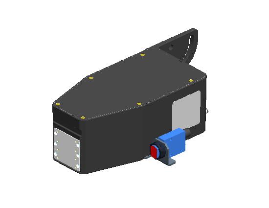
6 Integrated Valvejet 18 Dot - 6 -
7 - 7 -
8 - 8 -
9 Installation Instruction Sheet N Integrated Valve Print Head, 18 Dot Page 1 of 3 Wear safety goggles when performing the procedure.! Disconnect power during installation. INSTALLATION 1. Remove shipping tape from print head orifice plate. 2. Install print head on bracketry. Diagram 1 is an example of typical mounting. 3. Align print head with substrate. 4. Mount the regulator included with the print head.! DO NOT ATTEMPT TO CHANGE THE REGULATOR PRESSURE. IT IS SET AT THE FACTORY. 5. Ensure that the driver controller and ink delivery system have been installed. The print head electronic cable should be installed into the driver controller and routed to the print head. The ink outlet tubing (trunk line) from the ink delivery system should be installed and bled. 6. Connect the female (inlet side) of the regulator to the ink supply trunk line. 7. Connect the male (outlet side) of the regulator to the Ink Inlet, Supply Port on the rear of the print head. 8. Connect the print head electronic cable from the controller to the appropriate Print Head Cable Inlet port on the rear of the print head. 9. Every print head is shipped with a clear conditioning fluid. Connect an effluent bottle or comparable device to the Ink Outlet, Bleed Port on the rear of the print head until ink flows thru. 10. Hold an absorbent cloth(s) in front of the print head. Press and hold the PURGE button on the rear membrane switch until ink is ejecting from the print head front orifice plate. 11. While not printing or purging, the pressure on the print head LED display should be approximately 7 psi. This pressure will fluctuate while printing. 12. The print head is ready for printing
10 Installation Instruction Sheet N Integrated Valve Print Head, 18 Dot Page 2 of 3 PRINT HEAD OPERATION (Diagram 2) Initial Startup and Power Save: When the print head is connected to the electronic cable, the display shows the center decimal point to signify there is power. This is the Power Save mode. This mode saves energy by not powering all the LED display segments. The print head has full functionality in Power Save mode. Any of the four push buttons on the membrane switch will illuminate (wake up) the display. When awake, the display will always start in the Home Screen. Inactivity: After 30 seconds of inactivity in the Home Screen, the display will change to Power Save mode. If the LED display is in any other mode such as Purge or Pulse Width Adjustment, the LED display will default to the Home Screen after 30 seconds of inactivity, then Power Save mode (an additional 30 seconds). Home Screen: The LED state after waking up the print head display or the default after 30 seconds of inactivity. It displays the print head pressure in psi (pounds per square inch). PURGE Button: The PURGE button can be used in two different ways, one, to PURGE all channels at once, or two, to PURGE one channel at a time. From the Home Screen, press and hold the PURGE button on the rear membrane switch for one second. All of the channels will fire/eject ink for two seconds. If you continue to hold the PURGE button, then the print head will purge ink until you release the button. To purge individual channels, press the ENTER button once then the up and down arrows to select the desired channel (e.g. 1 thru 18). Again, press and hold the PURGE button for one second. Ink LED DISPLAY PRINT HEAD CABLE INLET PRINT HEAD CABLE EXIT. DAISY CHAIN TO NEXT PRINT HEAD. INK OUTLET, BLEED PORT Diagram 2 PUSH BUTTON MEMBRANE SWITCH INK INLET, SUPPLY PORT will eject from the selected channel for two seconds. To return to the home screen, press the down arrow button until Pr is selected, and then press ENTER. Otherwise, the print head will automatically return to the home screen after 30 seconds of inactivity. Pulse Width Adjustment: Hold down the up and down arrows simultaneously. The last channel to be accessed will be displayed. Press the ENTER button. The pulse width setting will be displayed. This value is relative and can range between 15 and 65. The higher the value, the larger the dot size, and vice versa. Generally, pulse width adjustment on a new print head is not recommended. These values are factory set. However, it may be necessary to increase pulse widths if there are long print head cable lengths in the daisy chain. Decreasing the pulse widths will likely result in missed dots at first start-up. If a pulse width is changed, the ENTER button must be pressed to save the new value(s). Again, press the down arrow until Pr is displayed. Press ENTER to exit to the Home Screen. Note: If the ENTER button is not pressed, the display will revert to the home screen after 30 seconds and the pulse width value will not be saved. ENTER Button: This button is used to move from one function to the next or saving pulse width adjustments. Up and Down Arrows: These buttons are used to select channels, enter Pulse Width Adjustment mode, and to adjust the pulse width values up or down. Er Display Code: If the display on the rear of the print head shows a flashing decimal, this means the print head has been driven in excess of its normal printing range and is now in overdrive protection. Pressing any of the four buttons on the rear of the print head will reveal the Er code. Consult the factory. To clear the code, press the ENTER button on the rear of the print head. Note that this code will only clear when the print head is not being overdriven

11 THEORY OF OPERATION Installation Instruction Sheet N Integrated Valve Print Head, 18 Dot Page 3 of 3 Integrated Valve inkjet technology utilizes electronically controlled solenoid valves to open and close the flow of pressurized ink thru a series of holes, channels, and small orifices. Regulated ink pressure is supplied to the rear of the print head. While the print head is printing or purging, ink is flowing thru the inlet port, tubing, filter, and finally into the valve control mechanism. When the print head printed circuit board receives data signals from the controller via the print head cable, a microcontroller on the pcb generates pulses to the appropriate solenoids. These solenoids in turn, connect directly to a sealing piston. The sealing piston presses against a membrane that seals off the flow of ink to the appropriate orifice(s). When the solenoid is energized the piston pulls away from the sealing membrane and ink pressure allows flow of ink thru that channel and out the orifice. The time that the solenoid is powered on is called the pulse width; therefore, if the pulse width is increased, the valve is allowed to flow more ink (bigger dot). Pressure is monitored via a sensor that is teed into the print head bleed tubing. The sensor sends voltage signals to the display board that are scaled and displayed as gage pressure on the rear of the print head
12 Print System Conveyor Mounting Kit Assembly Instructions N Revision A Page 1 of 1 ITEM PART NUMBER DESCRIPTION QTY X01400 BAR,1.5 X 3 X 14 LONG X01400 BAR,1.5 X 1.5 X 14 LONG BRACKET, CORNER, 3 HOLE BRACKET, CORNER, 4 HOLE END CAP, 1.5 X END CAP, 1.5 X T-NUT, DOUBLE, 5/ T-NUT, SINGLE, 5/ NUT, 5/16-18 HEX SCREW,5/16-18 X 5/8 BUTTON HD CAP,SS SCREW,5/16-18 X 1-1/2 SOC HD CAP,SS WASHER, 5/16 LOCK WASHER,5/16 FLAT 2 Note: This bracket kit can be assembled in two different configurations and can be used to mount all IV printheads. CAUTION: When the print system is setup in configuration "B" it may be possible for the carton being printed to make contact with the ink can. Items 9, 11, 12, and 13 are used to fasten the bracket assembly to the side of the conveyor Configuration "A" 8 10 Configuration "B"
Integrated Valvejet 9 Dot Print Head
 Integrated Valvejet 9 Dot Print Head What am I getting? What are the improvements? Diagraph is proud to release the new IV9 Dot print head. New features include: Environmentally Sealed housing for harsh
Integrated Valvejet 7 Dot Print Head
 Integrated Valvejet 7 Dot Print Head What am I getting? What are the improvements? Diagraph is proud to release the new IV7 Dot print head. New features include: Environmentally Sealed housing for harsh
Operations Manual. IV4000 Integrated Valve System Revision B
 Operations Manual IV4000 Integrated Valve System 5770-017 Revision B 1 Missouri Research Park Drive St. Charles, MO 63304 Service Line 1-800-526-2531 Illinois Tool Works Inc 2017 IV4000 Integrated Valve
Operations Manual Integrated Valve Ink Jet System
 Operations Manual Integrated Valve Ink Jet System 5760-107 Revision G 1 Missouri Research Park Drive St. Charles, MO 63304 ServiceLine 1-800-526-2531 Illinois Tool Works Inc 2008 IJ3000 Integrated Valve
The Pro/Classic Series Printhead angle can be set between 0 and 90. Common settings are shown below. 192/32 1 Print Head
 Pro/Classic Series Printhead Instructions 2464-172 Rev. H Getting Started Head Angle The Pro/Classic Series Printhead angle can be set between 0 and 90. Common settings are shown below. 90 32-39 27 352/32
Operations Manual. Integrated Valve Print System Revision B
 Operations Manual Integrated Valve Print System 5770-448 Revision B 1 Missouri Research Park Drive St. Charles, MO 63304 Service Line 1-800-526-2531 Illinois Tool Works Inc 2014 Print System Operations
Operations Manual. IJ4000 Impulse Jet System Revision E
 Operations Manual System 5765-018 Revision E 1 Missouri Research Park Drive St. Charles, MO 63304 Service Line 1-800-526-2531 Illinois Tool Works Inc 2019 Ink Jet System Operations Manual 5765-018 The
Installation Guide. Retrofit Kit for USB Ready Intraoral Systems
 Installation Guide Retrofit Kit for USB Ready Intraoral Systems Table of Contents Wall-Mount Retrofit Kit... 2 Introduction... 2 Connecting the Articulating and Horizontal Arm Cables... 2 Installing the
Operations Manual. IJ4000 Impulse Jet System Revision D
 Operations Manual IJ4000 Impulse Jet System 5765-018 Revision D 1 Missouri Research Park Drive St. Charles, MO 63304 Service Line 1-800-526-2531 Illinois Tool Works Inc 2018 Ink Jet System Operations Manual
Phase Loss Protection Upgrade. Phase Loss Protection Upgrade. In this bulletin:
 Phase Loss Protection Upgrade In this bulletin: Introduction... 2 Purpose... 2 General... 2 Applicability... 2 HD3070 Phase Loss Protection Upgrade Kit Parts... 2 Preparation... 4 Install the Phase Loss
Manual. LC-16 system. LC-16 Inkjet Printer 1
 Manual LC-16 system LC-16 Inkjet Printer 1 Index ENVIRONMENT. 3 OPERATOR S SAFETY 3 OPERATION SAFETY 3 PART 1 INSTALLATION AND PARAMETER SETTING 4 1) Preparing 4 2) Installation 4 3) Priming 4 4) Parameter
Procedure to Install an IO Expansion Cage Assembly in a Maxum II Modular Oven Analyzer
 Procedure to Install an IO Expansion Cage Assembly in a Maxum II Modular Oven Analyzer Difficulty Level: Medium Estimated time to execute: 1 Hour Revision History Issue Date Reason 001 5/31/2016 Initial
Removal and Installation 8
 Removal and Installation 8 8 Introduction 8-2 Service Calibration Guide to Removal and Installation 8-4 Window 8-8 Covers and Trims 8-12 Rear Tray 8-31 Rear Cover 8-32 Media Lever 8-33 Media Lever Position
Installation and Assembly: 2 x 2 Video Wall Ceiling Mount for 40" - 55" flat Panel Displays
 Installation and Assembly: 2 x 2 Video Wall Ceiling Mount for 40" - 55" flat Panel Displays Model: DS-VWT955-2X2 EXTENSION COLUMN (SOLD SEPARATELY) COMPATIBILITY Display width must be a minimum of 36"
Removal and Installation8
 8 Screw Types 8-4 Top Cover Assembly 8-5 Left Hand Cover 8-6 Right Hand Cover 8-10 Front Panel Assembly 8-14 Left Rear Cover 8-15 Right Rear Cover 8-16 Extension Cover (60" Model only) 8-17 Media Lever
Description: Detailed procedure on removing old bushing and installing new Brake Bushing Replacement Kit 10447
 Procedure: BRAKE BUSHING REPLACEMENT PROCEDURE Product: Document #: Rev: Page: MODEL 7000, 7000A, & 8000 GYRO 078 1 1 of 14 Description: Detailed procedure on removing old bushing and installing new Brake
Operations Manual WaxJet 192 System
 Operations Manual WaxJet 192 System 2466-400 Revision D 1 Missouri Research Park Drive St. Charles, MO 63304 ServiceLine 1-800-526-2531 Illinois Tool Works Inc 2007 Ink Jet System Operations Manual 2466-400
Economizer Regulator Filter Upgrade
 Overview Chart LNG has released a new and improved economizer regulator, and filtering system. The new economizer filter system is designed to enhance reliability, and offer lower operating costs. In 2012
User s Manual. Diagraph Ink Delivery System Stand-Alone (IDS/SA) Revision D
 Revision D") User s Manual Diagraph Ink Delivery System Stand-Alone (IDS/SA) 5802-677 Revision D Diagraph Corporation 3401 Rider Trail South Saint Louis / Earth City, MO 63045 2000 IDS/SA TABLE OF CONTENTS 1 IDS/SA
User s Manual Diagraph Ink Delivery System Stand-Alone (IDS/SA) 5802-677 Revision D Diagraph Corporation 3401 Rider Trail South Saint Louis / Earth City, MO 63045 2000 IDS/SA TABLE OF CONTENTS 1 IDS/SA
RL-H80 PARTS LIST # K
 RL-H80 PARTS LIST # 102837K USE THIS PARTS LIST FOR: Hoist Serial Number: 2733 to For older hoists use the following: Parts List No. 102837G for Serial Number 2485 to 2732 IF YOUR HOIST DOES NOT FALL WITHIN
DirectCommand Installation RoGator Model Year Ag Leader Technology
 Note: Indented items indicate parts included in an assembly listed above Part Name/Description Part Number Quantity Direct Command Kit 4100801 1 Dual Lock 2000052-9 1 Dual Lock 2000053-9 1 Quick Reference
Peel/Rewind Upgrade Kit
 Peel/Rewind Upgrade Kit Installation Instructions This kit includes the parts and documentation necessary to install the Peel/Rewind upgrade kit on the following printers: ZM400 ZM600 Read these instructions
G12/G12x USER S MANUAL
 G12/G12x USER S MANUAL TABLE OF CONTENTS SECTION 1 SLIDE CONFIGURATION SECTION 2 SLIDE CONFIGURATION ACCESSORIES SECTION 3 TABLETOP CONFIGURATION SECTION 4 TABLETOP CONFIGURATION ACCESSORIES SECTION 5
Sidewinder Pumps Inc. AC C1D2 Timer/Controller
 Sidewinder Pumps Inc. AC C1D2 Timer/Controller Page 1 of 14 Rev 4/26/17 Table of Contents 1. Warnings --------------------------------------------------------------------------------------------------
VJ-1614 INSTALLATION MANUAL
 VJ-6 INSTALLATION MANUAL Please read this manual before using Thank you for purchasing a MUTOH product. This manual explains the steps for unpacking, mounting and basic installation before using the MUTOH
Toucan LT board printer
 Toucan LT board printer Setup and Operating instructions Unpack the Toucan LT board printer as you would any Toucan LT. Follow all cautions associated with installing a standard Toucan LT. Change in wash
VJ-1604 INSTALLATION MANUAL
 Please read this manual before using Thank you for purchasing a MUTOH product. This manual explains the steps for unpacking, mounting and basic installation before using the MUTOH Full-color inkjet printer
Revision History E F G H J K Revision Description: K > Allegion Rebranding.
 Notes: Enter any notes here. These notes must include: how many sides of the paper are printed ink color (usually black, may also be one or two specific colors, such as a Pantone value, or 17.000 8.500
Field Calibration Check Procedure Minneapolis Duct Blaster System (with DG-700)
") Field Calibration Check Procedure Minneapolis Duct Blaster System (with DG-700) The following procedure uses a Duct Blaster Field Calibration Plate to perform a field calibration check on your Series B
Field Calibration Check Procedure Minneapolis Duct Blaster System (with DG-700) The following procedure uses a Duct Blaster Field Calibration Plate to perform a field calibration check on your Series B
Chemlock PFA and PP Filter Housings
 CONTAMINATION CONTROL SOLUTIONS Chemlock PFA and PP Filter Housings Installation and use manual Table of Contents Introduction... 2 Safety... 2 Specifications... 2 PFA... 2 PP... 2 Dimensions... 3 Minimum
RAM Rail Mount Kit RAM 201U 5 Arm RAM 2461U Monitor Mount RAM 235U Base, Double U-Bolt
 Note: Indented items indicate parts included in an assembly listed above Part Name/Description Part Number Quantity DirectCommand Kit 4100800 1 Cable Installation Kit 2000901-1 1 Dielectric Grease 2002872
VJ-1618 INSTALLATION MANUAL
 Please read this manual before using Thank you for purchasing a MUTOH product. This manual explains the steps for unpacking, mounting and basic installation before using the MUTOH Full-color inkjet printer
SERVICE PARTS MANUAL
 SERVICE PARTS MANUAL DX SERIES SNOW PLOW FOR SERIES SNOW PLOWS SERIAL NUMBERS AFTER DX0000 00 Sno-Way International 0G TABLE OF CONTENTS Page HYDRAULIC SYSTEM (DX)... POWER PACK FRAME... 3 BLADES... LIFT
Procedure to Replace a TCD DPM with an IS TCD DPM in a Maxum or Maxum II Analyzer
 Procedure to Replace a TCD DPM with an IS TCD DPM in a Maxum or Maxum II Analyzer Difficulty Level: Medium Estimated time to execute: 1 Hour Revision History Issue Date Reason 001 1/31/2017 Initial Issue
Basketball Shot Clock Set LX2180 Manual
 Basketball Shot Clock Set LX2180 Manual 72 Industrial Boulevard Wrightsville, GA 31096 Phone: (800) 445-7843 Fax: (800) 864-0212 www.electro-mech.com LX2180 Revision 5 February 8, 2013 Table of Contents
SENC 150 REFERENCE MANUAL
 SENC 50 REFERENCE MANUAL SENC 50 Table of Contents / Warnings Page Introduction / Supplied items... 4 2 Preparing the mounting / Mounting information... 5 3 Encoder dimensions... 8 4 Backup spar dimensions...
DirectCommand Installation 5 Channel Spreader Control Module Technology
 DirectCommand Installation Ag Leader Technology Note: Indented items indicate parts included in an assembly listed above Part Name/Description Part Number Quantity Direct Command Kit 4100582 1 Cable Installation
Mechanically Activated Device for Dry Run Protection in Applications with LORENTZ Solar Pump Systems
 Well Probe Mechanically Activated Device for Dry Run Protection in Applications with LORENTZ Solar Pump Systems The switch can be used to detect the water level within a well. When the water level in the
Installation Note for Isocratic-to- Quaternary Pump Upgrade Kit G1352A
 s1 Installation Note for Isocratic-to- Quaternary Pump Upgrade Kit G1352A In this note we describe how to install the isocratic-to-quaternary pump upgrade kit into an Agilent 1100 Series isocratic pump.
Installing the Server into a Rack
 Installing the Server into a Rack Note These instructions apply to multiple models; illustrations may vary slightly. Rack Mount Kit Inventory Before installing the chassis on a standard 4-post rack, make
Spraying System. Commissioning and maintenance manual. eco-control SC1200. for preeflow eco-spray
 Spraying System Commissioning and maintenance manual eco-control SC1200 for preeflow eco-spray 1 Table of contents 1. This manual................... 03 2. Designated use.................. 03 3. For your
TABLE OF CONTENTS SECTION 1 TABLETOP CONFIGURATION SECTION 2 TABLETOP CONFIGURATION ACCESSORIES SECTION 3 SLIDE CONFIGURATION
 S6 USER S MANUAL TABLE OF CONTENTS SECTION 1 TABLETOP CONFIGURATION SECTION 2 TABLETOP CONFIGURATION ACCESSORIES SECTION 3 SLIDE CONFIGURATION SECTION 4 SLIDE CONFIGURATION ACCESSORIES SECTION 5 RACK MOUNT
Cisco CRS 3-Phase AC Power Distribution Unit Installation Guide 2. Cisco CRS 3-Phase AC Power Distribution Unit 2
 Cisco CRS 3-Phase AC Power Distribution Unit Installation Guide Cisco CRS 3-Phase AC Power Distribution Unit Installation Guide 2 Cisco CRS 3-Phase AC Power Distribution Unit 2 Revised: November 18, 2016,
Differential Pressure ( P) Transducer US Patent
 Transducer US Patent") Differential Pressure ( P) Transducer US Patent 20070044865 Installation Liquid Controls An IDEX Energy & Fuels Business EM300-40 Table of Contents Safety Procedures Introduction Maintenance Safety...2
Differential Pressure ( P) Transducer US Patent 20070044865 Installation Liquid Controls An IDEX Energy & Fuels Business EM300-40 Table of Contents Safety Procedures Introduction Maintenance Safety...2
RD 100. Spare parts list. RD 100 s/n BES Construction Tools PC AB No
 RD 100 Spare parts list RD 100 s/n BES100496 2018 Construction Tools PC AB No. 9800153901 2018-10 General information This spare parts list applies to the following: Part number 8311030410 RD 100 Description
SECTION 8 - ULTRA & ULTRA-C PARTS CATALOGUE
 SECTION 8 - ULTRA & ULTRA-C PARTS CATALOGUE PART # DESCRIPTION PAGE MOUNTING KITS & TANKS 903U MOUNTING KIT WITH TANK 801-802 905U MOUNTING KIT WITHOUT TANK 803-804 902U MOUNTING KIT - CRADLE, BLOCKS &
DaNI Robot Camera. User Guide V0512
 DaNI Robot Camera User Guide 60018 V0512 Materials Included Camera (includes hardware that will not be used) Modem (with power supply that will not be used) Power converter 6" Velcro strip Adhesive tab
Operating instructions valve control box AS-i
 THIS LEAFLET SHOULD BE KEPT IN A SAFE PLACE FOR REFERENCE Operating instructions valve control box AS-i 1 System description The Norgren Herion valve control box is used for controlling pneumatic swivel
Encore XT Manual Gun Upgrade Kit
 Instruction Sheet P/N 1600823-01 Encore XT Manual Gun Upgrade Kit 1600834 Introduction Follow these instructions to upgrade your Encore manual spray gun to the improved design of the Encore XT spray gun.
SERVICE PARTS MANUAL
 SERVICE PARTS MANUAL 8 SERIES SNOW PLOW FOR SERIAL NUMBERS AFTER 8D100000 00 Sno-Way International 9100G TABLE OF CONTENTS PAGE DEFLECTORS... POWER PACK... HYDRAULIC POWER UNIT... LIFT CYLINDER... ANGLE
ERNG-X. Description. Applications. ERNG-X Specifications DERNG2108X012
 ERNG-X DERNG2108X012 Description The ERNG-X is a steady state no bleed engineered system for accurate and reliable control of Natural Gas. The ERNG-X includes a pressure regulator, preconditioning filters,
INSTALLATION INSTRUCTIONS
 Wired Remote Controller 7 Day Programmable Ductless Systems KSACN0401AAA (High Wall Models) KSACN0501AAA (Ducted/Cassette Models) INSTALLATION INSTRUCTIONS NOTE: Read the entire instruction manual before
Validator Update Instructions for Rowe BC1200 $1 - $20
 Validator Update Instructions for Rowe BC1200 $1 - $20 Kit Overview The purpose of the kit is to replace the Rowe BA50 transport and stacker with a 120 volt Mars validator with a compact mask. The kit
5 B&W Rear View System Camera
 5 B&W Rear View System Camera Instruction Manual MODEL: CA453 www.lorexcctv.com Copyright 2007 LOREX Technology Inc. Thank you for purchasing the Lorex 5 Black & White Rear View System Camera. This system
DSI-4. DMX Optically Isolated 1x4 Splitter. D Series. DSI_4 Users Manual r3.lwp copyright 2009, 2010, 2011 ELM V. T. Inc.
 DSI-4 DMX Optically Isolated 1x4 Splitter D Series 1 Table Of Contents IMPORTANT SAFEGUARDS... DSI-4 OVERVIEW... CONNECTION... PCB BLOCK DIAGRAM... SERVICING... TROUBLESHOOTING... SPECIFICATIONS... 2 3
H.A. Phillips Inventory Overstock Liquidation List
 H.A. Phillips Inventory Overstock Liquidation List ALL PRICES HAVE BEEN REDUCED All Items subject to verification of stocking. Items are sold as is. Please contact the factory (630-377-0050) for more information.
Raven Adapter Harness
 Note: Indented items indicate parts included in an assembly listed above Quantity by System Part Name/Description Part Number With Switch Box With Built-in Switches Raven Harness Adapter Kit 4100504 1
Adapter Kit for PanelView 1200/1200e Touch Screen Terminal Cutout
 Installation Instructions Adapter Kit for PanelView 1200/1200e Touch Screen Terminal Cutout Catalog Numbers 2711-NR5T, 2711P-RAT12E2 Topic Page About This Publication 1 Important User Information 2 About
SPCH/ Big bottle blowing block
 > > Blowing block for linear and rotating blow moulding machines > > Digital position indicator - counter with four decade from 000.0 to 00.0 > > Best suited for PET bottles from 5 up to 30 litres (up
Part Name/Description Part Number Quantity
 Part Name/Description Part Number Quantity Direct Command Kit 4100883 1 Installation Instructions 2006336 1 Hardware Kit Large Module 2001354-1 2 Cable Installation Kit 2000901-1 1 Quick Reference Card
RL-C20 PARTS LIST # G USE THIS PARTS LIST FOR: For older hoists use the following: Parts List No E for Serial Number 4200 to 14761
 RL-C20 PARTS LIST # 102688G USE THIS PARTS LIST FOR: Hoist Serial Number 14762 to For older hoists use the following: Parts List No. 102688E for Serial Number 4200 to 14761 IF YOUR HOIST DOES NOT FALL
E2460GS Oscilloscope Upgrade Kit
 Installation Instructions for E2460GS Oscilloscope Upgrade Kit Agilent 1670G-Series Logic Analyzers This kit upgrades either the Agilent Technologies 1670G, Agilent 1671G, Agilent 1672G, or the Agilent
GV-EL124S Electric Strike
 GV-EL124S Electric Strike Featured with a built-in door status sensor, the GV-EL124S is a fail-secure electric strike, but it is field convertible from fail secure to fail safe. It can be mounted either
Unpacking and Installing the Flora 2512 UV Printer. Steps 1: Unscrew the 10mm bolts holding the top. Then remove the top and put in a safe place.
 Unpacking and Installing the Flora 2512 UV Printer Steps 1: Unscrew the 10mm bolts holding the top. Then remove the top and put in a safe place. Step 2: Unscrew 10mm bolts holding the end panels. On the
SITRANS F. Flowmeters SysCom Upgrade Kit IP65 (NEMA 4X) Multi-Channel. Introduction 1. Installing/Mounting 2. Hardware Installation Instructions
 Multi-Channel. Introduction 1. Installing/Mounting 2. Hardware Installation Instructions") Introduction 1 Installing/Mounting 2 SITRANS F Flowmeters SysCom Upgrade Kit IP65 (NEMA 4X) Multi-Channel Hardware Installation Instructions 1/2010 A5E02518333A Revision 04 Legal information Warning notice
Introduction 1 Installing/Mounting 2 SITRANS F Flowmeters SysCom Upgrade Kit IP65 (NEMA 4X) Multi-Channel Hardware Installation Instructions 1/2010 A5E02518333A Revision 04 Legal information Warning notice
PowerFlex 755 Transition Section and Splicing Kit for Floormount Drives and CENTERLINE 2100 Motor Control Centers
 Installation Instructions PowerFlex 755 Transition Section and Splicing Kit for Floormount Drives and CENTERLINE 2100 Motor Control Centers Topic Page Introduction, Compatibility 1 Additional Resources
9 Maintenance and Repair
 Agilent 1200 Infinity II Series RID User Manual 9 Maintenance and Repair Introduction to Maintenance 120 Warnings and Cautions 121 Overview of Maintenance 123 Cleaning the Module 124 Storage of the Detector
ABM International, Inc. Lightning Stitch Checklist 9/13/2013
 ABM International, Inc. Lightning Stitch Checklist 9/13/2013 1) Piggy backed board assembly (1) Piggy back board assembly tested? Yes No 24v passed XB passed XA passed YB passed YA passed SAFE passed S/S
To be used for reference only Property of Arc Machines, Inc.
 MODEL 9-1500 IPB Notice and Revision History This document and the information contained herein is the property of Arc Machines, Inc. It is proprietary and submitted and received in confidence. It shall
Table of Contents: TOPIC: Safe Operation: READ THIS FIRST Page: 3 Warranty 4 Specifications 4 Installation 5-7 Operating Instructions 8 Parts Diagram
 INSTALLATION & OPERATIONS MANUAL FlexArm B-19 FlexArm Inc. Division of Midwest Specialties, Inc. 851 Industrial Drive Wapakoneta, Ohio 45895 419-738-8147 Book Part No 360740 12/2014 1 Table of Contents:
Model QRS CPVS
 SPARE PARTS LIST EN CP COMPRESSOR Model QRS 0-5 - 0 CPVS 0-5 - 0 6 05 50 65 KEY - Door Panel: 655900 Lock - Door Panel: 005076 QRS 0 CONTENTS Title Page MAINTENANCE HOW TO READ THIS SPARE PART LIST? KIT
xtablet T1600 Vehicle Holder Installation Guide
 This document will step you through setting up the T1600 Vehicle Holder installation and tips for a safe, clean and long lasting installation. Preparing to Mount the Vehicle Holder Warning : Dock mounting
Sensor Accessories Retroreflectors and Retroreflective Tape Sensor Mounting Brackets Sensor Accessories. 52.
 Retroreflectors Sensor Accessory AC Sensor Tester/Demonstrator Pilot Device E65 Control Unit.1 Retroreflectors and Retroreflective Tape Product............................................. 414 Application..........................................
Marksman. Duo XT. Pro-Series AN ITW COMPANY. High Resolution Printing. Real World. for the. Operations Manual Revision D.
 Marksman Duo XT Pro-Series AN ITW COMPANY High Resolution Printing for the Real World Operations Manual 5765-313 Revision D www.foxjet.com 1 Missouri Research Park Drive St. Charles, MO 63304 Tel: 800-369-5384
E1135C PDU and Pod Upgrade Procedure
 E4030-90010 Rev. B 12/2003 In this Document... Tools Needed, 2 Contents of the Upgrade Kits, 2 Installation Procedures, 4 Verifying the Power Option of the New PDU, 4 Removing the PDU from the Support
Ag Leader Technology. DirectCommand Installation Hardi 20-pin Interface Kit (Sprayer Chassis Mount)
") Part Name / Description Part Number Quantity DirectCommand Hardi Sprayer Kit 4100882 1 Dust Receptacle 8-pin 2002975-8C 1 Installation Instructions 2006335 1 Quick Reference Card- Liquid Application 2002831-38
Part Name / Description Part Number Quantity DirectCommand Hardi Sprayer Kit 4100882 1 Dust Receptacle 8-pin 2002975-8C 1 Installation Instructions 2006335 1 Quick Reference Card- Liquid Application 2002831-38
Flat Panel Static Wall Mount MSP-SS (GSM-210)
") INSTALLATION INSTRUCTIONS Flat Panel Static Wall Mount (GSM-2) The static wall mount fits most 23 to 30 displays. The mount was designed to adapt to the VESA 75mm/0mm, 0mm/0mm, and 200mm/0mm compliant
INSTALLATION INSTRUCTIONS Flat Panel Static Wall Mount (GSM-2) The static wall mount fits most 23 to 30 displays. The mount was designed to adapt to the VESA 75mm/0mm, 0mm/0mm, and 200mm/0mm compliant
DIGITAL OBSERVATION GUARD LOW PROFILE PAN TILT KIT USER MANUAL
 DIGITAL OBSERVATION GUARD LOW PROFILE PAN TILT KIT USER MANUAL Version 2.1 June 4, 2013 0 Table of Contents Low Profile Pan Tilt Kit Description... 3 Low Profile Pan Tilt Unit Basic Operation... 4 Mounting
Ag Leader Technology Insight. Direct Command Installation Spra-Coupe 7000 Series
 Note: Indented items indicate parts included in an assembly listed above. Part Name / Description Part Number Quantity Direct Command Spra-Coupe 7000 Kit 4100531 1 Liquid Product Control Module 4000394
Seeburg JCU-DEC Kit Convert Your Seeburg DEC Wallbox Into a Jukebox
 Seeburg JCU-DEC Kit Convert Your Seeburg DEC Wallbox Into a Jukebox MP3 Compact Flash Player Coin Operated or Free Play Integrated Power Amplifier Line-Out to External Amplifier Programmable Autoplay IR
The power behind competitiveness. Delta Infrasuite Power Management. Power Distribution Unit. User Manual.
 The power behind competitiveness Delta Infrasuite Power Management Power Distribution Unit User Manual www.deltapowersolutions.com Save This Manual This manual contains important instructions and warnings
BNI PBS Z001 BNI PBS Z001 BNI PBS Z001 BNI PBS Z001 Short Guide
 BNI PBS-104-000-Z001 BNI PBS-302-000-Z001 BNI PBS-501-000-Z001 BNI PBS-502-000-Z001 Short Guide English 1 2 3 4 Notes to the User 3 1.1 About this guide 3 1.2 Structure of the guide 3 1.3 Typographical
HDMI Upgrade for the Showcase DVD
 THE LEADER IN AUDIO ENGINEERING for the Showcase DVD INSTALLATION AND SETUP GUIDE Getting Started THERE ARE NO USER- SERVICEABLE PARTS INSIDE ANY KRELL PRODUCT. Krell authorizes this HDMI upgrade to the
APES-14 HD-6500 & HD-7000 Version Operator s Training Manual
 APES-14 HD-6500 & HD-7000 Version Operator s Training Manual Issue A1 09/03 PDI Part # 900600 Performance Design Inc. 2350 East Braniff St. Boise Idaho 83716 This manual contains very important safety
V5420 Host Card Upgrade Kit for R3082D Quick Start Guide
 Quick Start Guide Upgrade kit contents The table below shows the contents of the V5420 Host Card Upgrade Kit (components are not shown to scale). Part Function Pieces V5420 Host Card 1 Host card bracket
Scanner 2000 microefm QuickStart. Installing the Scanner Remote Mount. Direct Mount NUFLO. Part No , Rev. A
 NUFLO Part No. 30165024, Rev. A Scanner 2000 microefm QuickStart Installing the Scanner 2000 H L H L Flow Direct Mount To install the Scanner 2000 microefm using a direct mount to an orifice or cone meter
DIMENSION/WEIGHT kpa. 0 to 20 m / 0 to 60 ft 0 to 2 bar / 0 to 29 psi. 0 to 50 m / 0 to 160 ft 0 to 5 bar / 0 to 72.5 psi
 V161102 Liquid Level Sensor Sensor for measuring the level of liquid in a well or tank USE / PURPOSE The range of liquid level sensors use pressure to measure the liquid level in a well or tank. The sensors
SCVA08, SCVA10, SCVA20 & SCVA32, 3/2 Solenoid actuated safety valve
 SCV0, SCV0, SCV & SCV, / > > Port size: /4, /, /4 and (ISO G, NPT) > > Range of sizes - DN, 0, and > > Redundant valve assembly, pneumatic self monitoring with integrated safety silencer > > Ensures safe
Olympus BX43 and BX46 Installation Instruction for Microscope End Users (easy install version) 4
 4") Olympus X and X6 Installation Instruction for Microscope End Users (easy install version) PN 07 Olympus X_6 Illuminator ssy dditional Items Included ut Not Shown: PN 077 Hex Key mm PN 060 Hex Key mm M
Olympus X and X6 Installation Instruction for Microscope End Users (easy install version) PN 07 Olympus X_6 Illuminator ssy dditional Items Included ut Not Shown: PN 077 Hex Key mm PN 060 Hex Key mm M
Octostrip ORDERCODE 42220
 Octostrip ORDERCODE 42220 Congratulations! You have bought a great, innovative product from Showtec. The Showtec LED Octostrip brings excitement to any venue. Whether you want simple plug-&-play action
Print Mechanism Maintenance Kit
 Print Mechanism Maintenance Kit Installation Instructions This kit includes the parts and documentation necessary to install the print mechanism maintenance kit in the following printers: ZT0 ZT0 ZT0 Read
OPERATING USER MANUAL for PRESSURE RECORDERS
 Serial No. OPERATING USER MANUAL for PRESSURE RECORDERS MNW-004 Rev. E 03/21/16 Palmer Instruments Inc. 234 Old Weaverville Road Asheville, NC 28804 Toll Free: 800-421-2853 Phone: 828-658-3131 Fax: 828-658-0728
Part Name/Description Part Number Quantity
 Part Name/Description Part Number Quantity Direct Command 4200159 1 Cable Installation Kit 2000901-1 1 Hood 37-pin DSub 2001808-37 2 Dielectric Grease 2002872 1 Dust Plug 12 Pin Gray 2002899-12N 1 Feature
Service Manual. Subject Issued By. Date MM/DD/YY 29/06/17. Hybrid Atom Printhead Customer Support Team ITEM PART NUMBER QTY
 Service Manual 1738 Orangebrook Court, Unit #1 Pickering, ON L1W 3G8 Tel : (905) 839-6018 Fax : (905) 839-6023 Subject Issued By Hybrid Atom Printhead Customer Support Team Date MM/DD/YY 29/06/17 F G H
Ribbon Supply Spindle Maintenance Kit
 Installation Instructions This kit includes the parts and documentation necessary to install the Ribbon Supply Spindle Maintenance Kit in the 105SL printer. Read these instructions thoroughly before installing
Air Mask PARTS LIST High Pressure
 Air Mask PARTS LIST High Pressure TAL 0 (L) Rev. MSA 00 Prnt. Spec. 000000 (A) Mat. 000 Doc. 000000 pressure demand facepiece NFPA Facepiece Components Facepiece Blank Type Small Medium Large Hycar 00
DOT MATRIX PRINTER SP6000 SERIES
 DOT MATRIX PRINTER SP6000 SERIES Hardware Manual < Approval: CEL > Trademark acknowledgments SP6000 : Star Micronics Co., Ltd. Notice All rights reserved. Reproduction of any part of this manual in any
RAM Rail Mount Kit RAM 201U 5 Arm RAM 2461U Monitor Mount RAM 235U Base, Double U-Bolt
 DirectCommand Installation Ag Leader Technology Note: Indented items indicate parts included in an assembly listed above Part Name/Description Part Number Quantity DirectCommand Kit 4100852 1 Cable Installation
Components. Tools for Setup. Installation Outline
 VANTAGE PRO AND VANTAGE PRO PLUS Fan-Aspirated ISS Retrofit Kit Installation Instructions Estimated Time Required: 60 Minutes These instructions describe how to install the Vantage Pro Fan-Aspirated Integrated
Sidewinder Pumps Inc. AC Timer/Controller
 Sidewinder Pumps Inc. AC Timer/Controller Page 1 of 12 Rev 032417 Table of Contents 1. Warnings-------------------------------------------------------------------------------------------------- 3 1.1.