VALICHANGER OPERATIONS MANUAL SERIES AC2005
|
|
|
- Morris Harper
- 5 years ago
- Views:
Transcription
917-5204 Internet Address: www.americanchanger.com Service Questions?: E-mail: service@americanchanger.")
1 1 A-3 VALICHANGER OPERATIONS MANUAL SERIES AC2005 American Changer Corp Parts & Service:(888) th Place Sales:(800) Ft. Lauderdale, FL Parts & Service Fax:(954) Internet Address: Service Questions?: Table of Contents SECTION A: SET-UP & INSTALLATION Hopper Error Codes 2 Uncrating & Setup 3 Mounting instructions 3-4 Filling the Hoppers 4 Using the Dump Mode 4 DIP Switches 4+6 Hopper Pay out Table 5 Bonus Pay Out Table 6 Payout sub modes 7 Fuse 7 Wiring definitions 7 Indicator Lights 7 About the Hopper/Coin sizes 8 Functional Descriptions 9 SECTION B: VALIDATOR INFO CoinCo to Mars Setup 10 CoinCo Validator information Mars Validator information SECTION C: HOPPER INFO Un-Jamming the Hopper SECTION D: TROUBLESHOOTING INFO Troubleshooting Guide 30 Technical Flow Diagram SECTION E: PARTS LISTS Cabinet Parts Breakdown 33 Parts Hopper MKIV 34 Parts CoinCo Bill Validator Parts MARS Bill Validator Mars Service Centers CoinCo Service Centers 45 Specifications Operating voltage 120 VAC +10/-15 % Power consumpt.(controller only, add hopper and validator)10w Operating temperature degrees Fahrenheit Interface to Hoppers 24vdc & 12vdc 1.5 amps max. Interface to Validators 120vac.5 amps max. Warranty CoinCo MAGPRO 00 B & MARS AE2601 Validator is warranted for two years from date of purchase. COVERED Defect in workmanship or material. NOT COVERED Damage caused by physical abuse. Misapplication Vandalism End users attempt, on his own to repair item Cleaning maintenance It is the End User s responsibility to follow cleaning maintenance procedure outline on page 15/19. Any unit coming in for repair requiring only a cleaning will be charged a flat rate of $65.00 plus shipping and handling. Dispensing System and Logic Board The dispenser and logic board is warranted for one year from date of purchase. COVERED Defects caused by material or workmanship. NOT COVERED Damage caused by physical abuse. Misapplication Vandalism End Users attempt, on his own to repair. A Return material authorization number (RMA #) must be obtained before returning a unit for repair. A copy of invoices must accompany any and all warrantee work. Rev. DBCG-1-A Jan 04
2 Attention Please: American Changer is now building in a Surge Suppressor on every main logic board made after September 1 st, This will help eliminate power related noise problems for our customers. It will not protect you from large voltage spikes or lightning strikes over 150VAC. If this is a concern for your area of business, we recommend purchasing a surge protector locally NOTE: A POWER STRIP IS NOT A SURGE PROTECTOR. Thank You, American Changer Corp. (888) DIP SWITCHES MAIN LOGIC BOARD (ON BACK WALL OF CABINET) QUICK CODE FAULT DEFINITIONS BILL METER / ERROR CODES DUMP BUTTON LEFT DIGIT ALWAYS 0. IGNORE! RIGHT HOPPER ERROR CODE. LEFT HOPPER ERROR CODE. Press the DUMP Button before turning off changer. Match the code to samples below to find out why the hopper(s) were shut down LEFT HOPPER ERRORS - NO ERRORS - LOW COIN - EXIT WINDOW JAM - BAD HOPPER BOARD - JAMMED - JACKPOT PREVENTED RIGHT HOPPER ERRORS NO ERRORS - LOW COIN - EXIT WINDOW JAM - BAD HOPPER BOARD - JAMMED - JACKPOT PREVENTED IF THE EMPTY LED IS LIT, LOOK FOR CODES FOR BOTH HOPPERS TO BE DISPLAYED!!!!!!!! 2
3 3 UNCRATING AND SET-UP Remove your AC2005 changer from the shipping box. Open the door. (The T-handle is a screw-in type and therefor, must be turned at least 10 times counter-clockwise until it opens.) Inspect for any connectors or components that may have been dislodged during shipping. The lock and keys for your changer will be inside the manila envelope along with this manual. To install the lock, insert the cylinder into the round hole in the middle of the T-handle and push until it stops. Now turn the key and lock until you hear it snap." Turn the key counterclockwise ¼ turn and remove the keys. NOTE: The only way to get a duplicate set of keys made is to save the red tag that comes between the keys. This ID # starts with ACC ####. Write your Key # here ACC. ALL KEY ORDERS TAKE 4-6 WEEKS!!! NOTE: THE METER ON THE MAIN LOGIC BOARD CANNOT BE RESET TO ZERO!!! TEST: Before permanently installing the changer, do a functional test to verify that there is no shipping damage to your new changer(s). Extend the power cord through the hole in the back of the changer or the bottom and plug it into a grounded 120vac outlet. The dip switches are already set for a 4 coin per dollar payout of the hoppers, and the Bill validator is ready to accept $1-$5-$10-$20 dollar bills. Fill the each hopper with at least 100 coins. On the main logic board turn the switch on the bottom right corner ON". (SEE FIG. 1 ON PG.3) The rocker switch has a 1 and 0 printed on it. When the 1 is pressed down the changer is ON. MOUNTING THE AC2005 TO A WALL IF YOU ARE UNSURE IN ANY WAY IN PROCEEDING WITH THE FOLLOWING STEPS, PLEASE HIRE A LOCAL PROFESSIONAL ELECTRICAN TO MOUNT YOUR CHANGER FOR YOU! 1. Disconnect any and all AC power going to the series 2001 changer. (See fig. 1) A. Unplug the AC line cord from the bottom of the board. B. Unplug the validator connectors on the right side of the board. C. Unplug the hoppers harness connectors on the left side of the board. D. Unbolt the ground wire from the right side of the cabinet. E. Remove the main logic board and hoppers from the inside of the changer. F. Put the nuts back on the studs to avoid losing the brass spacers on the studs. 2. Slide the hoppers out of the cabinet. 3. Note: You will need to verify with the building code to see that is allowable to plug the changer into a 3 prong grounded outlet. If it is not, there must be 120VAC run through conduit to the changer. If it is not required, proceed to step #6. 4. Let the electrician run the conduit, install the new breaker, wire and help decide how the wiring will enter the changer (from the back or the bottom). This will affect the mounting location. 5. After the conduit has been installed, proceed with the mounting. 6. Locate the 4 punch-outs on the back wall of the changer. Using a screwdriver and hammer knock the punch-outs out by hitting them from the inside of the changer. 7. Using a stud locator, find a location to hang the changer by locating the wall studs. 8. Find an appropriate wall to bolt the changer into. The wall should have studs or be constructed of concrete. Consult a professional with any questions you may have. 9. NOTE: HANGING THE CHANGER FROM LESS THAN ALL 4 HOLES MAY BE DANGEROUS. EACH HOLE NEEDS A BOLT THROUGH EACH ONE MOUNTED SECURELY TO THE WALL. MOUNTING THE CHANGER IN ANY OTHER WAY MAY RESULT IN THE CHANGER BEING TORN OFF OR FALLING OFF THE WALL RESULTING IN PERSONAL OR CUSTOMER INJURY ALONG WITH ELECTRICAL SHOCK. 10. Choose a height to mount the changer keeping in mind that a handicapped person in a wheelchair should still be able to insert a bill into the bill validator. (We recommend no higher than 4 feet above the ground.) 11. Have someone hold the changer against the wall while someone else marks the holes. CAUTION: THE CHANGER WEIGHS 85 POUNDS DO NOT EXERT YOURSELF SO THAT YOU MAY CAUSE AN INJURY. 12. BEFORE DRILLING THE FOUR MARKED HOLES ENSURE THAT THERE ARE NO ELECTRICAL WIRES, TELEPHONE LINES, GAS, OR WATER LINES BEHIND THE WALL WHICH DISRUPTING MAY CAUSE A LOSS OF LIFE OR PERSONAL INJURY! 13. Hold the changer back up to the wall. Thread and tighten bolts. 14. Verify that the machine is securely mounted. 15. Reinstall the main logic board. A. Before installing the main logic board, verify that the plastic safety-insulating sheet is still against the back wall where the board will be mounted and that there is a 3/8 spacer on each stud. B. Install the main logic board and properly tighten the nuts. C. Re-bolt the ground wire into the right side of the cabinet. D. Plug the validator connector into the right side of the board. E. Plug the hoppers harness connectors into the left side of the board 16. If the changer is permanently connected through a conduit, proceed to step # Feed the AC line cord out the bottom or the back of the changer then perform the following. A. Connect the AC line cord into the bottom of the main logic board. B. Plug the male end into the AC wall outlet. Do not use an extension cord unless allowed by the building electrical code. C. Important: Attach the line cord clamp to the line cord. Verify it is at the right length and that the line cord is not rubbing against any sharp edges or is
4 4 being strained in any way. Then mount the line cord clamp to the studs at the hole. Tighten securely. Installation is finished and you can proceed to the Filling the Hopper section. 18. In order to continue you will need to purchase electrical cable conduit, a standard 3-prong AC wall outlet and 12- gauge wire. We highly recommend HIRING a qualified electrician to perform the following! A. Install the conduit box on the conduit entering the cabinet in the lower right side of the cabinet. B. Secure the 3 wires (hot, neutral, and ground) to the AC wall outlet and the ground wire should also be directly attached to the cabinet ground terminal. C. Connect the AC line cord into the bottom of the main logic board. D. Plug the male end into the AC outlet just installed. E. Properly fold the line cord to avoid sharp corners and any other damage. 19. Proceed to the Filling the Hoppers section. EPROM CHIP D B C G DIP SWITCHES MAIN LOGIC BOARD Figure BILL METER DUMP BUTTON FILLING THE HOPPERS When each hoppers has less than coins left the red Empty LED will light on the front of the changer. If you have disconnected your LED make sure the orange wire is going to the terminal on the LED that has the red wired terminal. Whenever the Empty LED is ON the validator is disabled and it will no longer accept bills. 1. Turn OFF the power on the main logic board. 2. Slide the hoppers out from the cabinet and insert the coins through the opening on the top. There must be at least enough coins to cover the two gold plates at the bottom of the hoppers. (Somewhere between 160 and 1600 coins minimum to maximum.) 3. Slide the hoppers back into the hopper plate. Do not use excessive force! 4. Turn ON the power switch. The Empty LED is now off and the bill validator is ready to accept bills. USING THE DUMP MODE TO EMPTY THE HOPPERS 1. Open the cabinet door. 2. Turn OFF the POWER switch. 3. Place a suitable container in front of the hoppers to catch the coins. 4. Press and hold the DUMP button on the upper right corner of the Main Logic Board. Turn ON the Power switch. The red LED numbers on the main logic board will come on all s. Once the red s lights up the SECOND time, release the DUMP button. If it is not released within one second, the DUMP mode is canceled as a security feature. 5. The hoppers will dispense coins until the POWER switch is turned OFF. If the red LED numbers are not counting up rapidly on the Main Logic Board s display the dump mode was not accessed. Please try again. THE DIP SWITCHES The 2005 series changer is capable of dispensing coins in many different pay out modes. Setting the coins out per dollar is controlled by which Dipswitches turned ON." (Refer to figure 1 for their location.) For example, switch #3 & #5 is ON on the left DipSwitch; the payout equals 4 coins per dollar. Two coins alternating per hopper for one dollar. HOPPERS HARNESS CONNECTORS 1 0 VALIDATOR CONNECTOR PRIMARY 2 1/2 AMP FUSE ON/OFF SWITCH ON FIGURE 2 (THIS IS NOT THE DIPSWITCH BANK FOR SETTING THE BILL DENOMINATIONS. (For those dip switches go to page ) TRANSFORMER AC LINE CORD INPUT
5 5
6 6
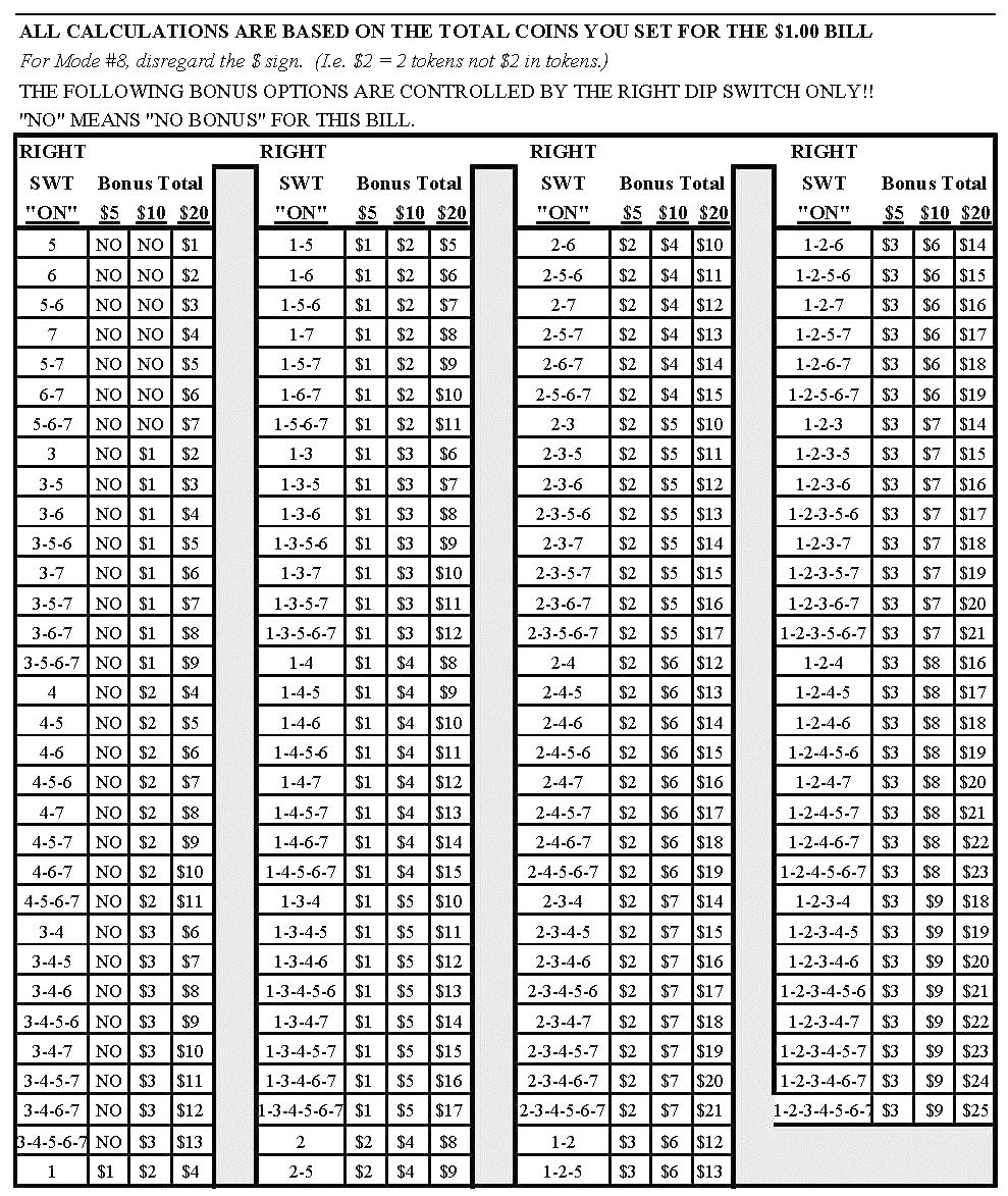
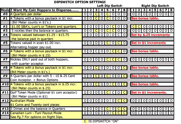
7 7 HOW TO USE THE BONUS TABLE Think of the bonus table as the total amount of EXTRA tokens after the regular payout, that you wish to receive: EXAMPLE: PAYOUT: 4 tokens for $1, 24 for a $5, 52 for a $10, 120 for a $ tokens = $1 extra in tokens 52 tokens = $3 extra in tokens 120 tkns = $10 extra in tokens. Now go to the bonus table, find where the $5 column =$1 Look over to the $10 and go down until you see $3. Finally go to the $20 column to where = $10. You should be at 1-3-7; Turn ON your right dipswitches to set this payout. DIPSWITCHES The following table shows how to set the dip switches to your desired payout. ON COINS PER DOLLAR #1 1 #2 2 #3 4 #4 8 The left DipSwitch controls the left hopper s pay out and the right DipSwitch controls the right hopper s pay out. Refer to the next table to set up your changer for the settings you need. MODE DESCRIPTIONS Some of the modes are self-explanatory while others have sub modes built into the chip. Here is a list of the modes and sub modes when applicable. MODE 2 - $1 coins the balance in quarters: The quarters for each bill are controlled by the sub mode settings of the right dipswitches #1 & #2. Neither ON 16 Quarters balance in $1 coins. #1 ON only 8 Quarters balance in $1 coins. #2 ON only 12 Quarters balance in $1 coins. #1 & #2 ON 4 Quarters balance in $1 coins. MODES #5 & #11 Setting right dips in $1 increments : Refer to Page 6 Under Dipswitches Cont.. But instead of counting up in coins, think of it as dollars. MODE #14 Canadian $1 &$2 coin payout: The right dipswitches #1 & #2 can alter the amount of $1 coins given to each denomination. Luni s per $ $5 $10 $20 Neither ON - 1L 0L 0L #1 ON 3L 2L 2L #2 ON 3L 4L 4L The machine will always give 2 Luni s for a Tuni. FUSE High voltage fuse: This is the primary transformer AC fuse for the main logic board and the validator. Any direct short of the Transformer or validator will cause this fuse to blow. Replace this fuse with a 2-½ amp AS fuse only. REPLACING THIS FUSE WITH ANYTHING OTHER THAN A 2 ½ AMP GDC MAY RESULT IN A FIRE OR AN UNSAFE WORKING CONDITION!! (See fig. 1 for location of this fuse.) Indicator Lights Main Logic Board: 1. Green LED on: AC power applied to the logic board. All fuses are good. 2. Decimal Point: A. Heartbeat - 5 and 12vdc present. The changer is in standby waiting for a bill pulse. B. On Steady - Out of service, Hopper error detected. Validator logic board: 1. Red LED A. On Steady - Standby Mode, waiting for bill insertion. B. Flashing - Error mode, go to page for error code information. C. Off - The changer Empty LED is lit. WIRE HARNESS COLOR AND DEFINITIONS Validator harness: Red - Switched Hot 120VAC White - Neutral 120VAC Black - 120VAC Low current validator enable Yellow - +5vdc credit pulse line Blue - -5vdc credit pulse line Orange - +12vdc Empty LED Brown - -12vdc Empty LED Hopper Harness Gray - Coin counting optic status line White - Low coin sense (+5vdc) Green - Coin counting optic pay out feedback line Yellow - Raw sensor output line Purple - Hopper pay out line from main logic board (+) Brown - Hopper pay out line from main logic board (-) Red - +12vdc logic board supply voltage Black(s) -12v, 24v low coin sense ground Orange - +24vdc Motor supply voltage
8 8 Coin/Token Sizes The hoppers will automatically adjust to dispense coins/tokens in size from mm in diameter and mm in thickness. There is an option available to dispense smaller coins. A nickel is approximately 21 mm, a quarter is approximately 25mm. A Susan B. Anthony is 28mm Coin Control Hopper MKIV Three green LED indicators are fitted on the hoppers and are visible in the section where the coins exit the hoppers. From left to right these are designated as follows: 1. Logic power supply on (12 & 24vdc present). 2. Security optical obstruction indicator -. Should be on when unit is OK. 3. Output indicator, indicates coin passing photo-sensor. This is the optical sensor the coin will obstruct on its way out of the hoppers. For normal operation LED # 3 will be off until coins are dispensed. Coin counting LED. Security LED. (all systems 12vdc Power Coin counting Hopper coin bin. (Dump the coins into this hole coins max.) Error HOPPER ERROR CODE DEFINITIONS Ignore Left Hopper Normal Right Hopper The DBCG-1 EPROM chips allow for the hoppers to run in a one-hopper mode if one hopper goes down and the ability to explain why that hopper was shut down. To access this mode press the DUMP button while in the normal operating mode. The meter display will disappear and be replaced by the error readout. You will know if you are in the one-hopper mode if only one hopper is dispensing coins, one hopper is full and the other is empty, or that your far-left decimal point on the light-up display is lit instead of the far-right. The most left display (#1) is not used. The #2 & #3 display are for the left hopper and #4 & #5 display are for the right hopper. Here are the error code definitions: 01=Low coin. 02=Object stuck in optic window. 04=Did not pay enough coins. 10=Paid too many coins (2 max) Jackpot protection! An error read-out of states the left hopper was shut down due to low coins. A read-out of states an optic window failure and low coin was detected. I.e = pin male connector. (located on the opposite Motor The right & left hoppers have a removable coin chute installed. Replacement hoppers are not sent with this coin chute. Left chute (P# AC ) Right chute (P# AC
9 9 Functional Description of the Series AC2000 Changer To follow along with this walk-through of your changer, fill the hoppers with coins and turn the changer on. 1. When power is applied the validator will cycle twice, the out-of-service LED flashes then goes out, the green LED on the main logic board comes on steady, and the decimal point on the main logic board number display will flicker on once per second in the standby mode. 2. During the power-up mode the main logic board relay clicks twice enabling power (120vac) to the validator. When this relay is not enabled it routes 12vdc ground to the out-ofservice LED. Without power to the validator the changer cannot accept bills. Since we are not in the error mode, the red LED on the validator logic board is on steady. 3. When a bill is inserted into the validator bill slot, the bill will be pulled inside. The validator then compares what the bill looks like to its memory. After the bill is validated it grounds the 5vdc lines causing a pulse along the yellow and blue validator harness wires to pins 5 and 15 of the main logic board. Each pulse stands for the amount of the denomination validated. (i.e. 1 pulse for $1, 5 pulses for $5). 4. The 5vdc pulse then travels from pins 5 and 15 to the EPROM chip (ver. DBCG-1 ) pin #25. The EPROM sends a 12vdc pulse to the meter chip (U5) out pins #21 5. & 22 (one pulse per denomination validated). The EPROM also multiplies the bill pulse by the DipSwitch settings (The EPROM reads the DipSwitch settings during the power up mode and stores them into memory.) 6. The EPROM then sends the hopper pulses out pin #23 to pins 6 and 7 of the red 12 pin hopper plugs. These pulses travel through the purple and brown wires of the hoppers wire harness to the hoppers pins 8 and The hopper turns itself on with the first hopper pulse. The hoppers counts the hoppers pulses sent from the EPROM chip on IN3 (pin 12) while dispensing the coins at the same time. When the amount of hoppers pulses in equals the coins dispensed through the coin counting optical sensor the hopper turns itself off. 8. The Changer returns to the standby mode with the decimal point flashing once per second until another bill is inserted. Functional Descriptions of Out-of-Service Conditions Out-of-Service conditions occur for the Series 2000 changer for the following reasons; low coins, hopper fault error, validator fault, or a blown fuse. 1. Blown Fuse: an AC power spike in line voltage or a bad transformer on the main logic board can cause A blown fuse on the main logic board. If either fuse blows the indication is the green LED on the main logic board will not light. A. Replace the fuse. If the green LED now lights then there was a spike. B. If it does not and the fuse blows again the power transformer is shorted. To test the transformer use a voltmeter set for ohms and measure across the primary (40ohms) and the secondary (1.5ohms). 2. Hopper Fault: A hopper fault can either be a jammed hopper, a blocked coin counting optic or a bad hopper logic board. A. Indications for a jammed hopper are the changer accepts bills, the meter counts up, but nothing or not enough coins are paid out. 1. After 2 minutes the EPROM shuts off the validator if the coins are not paid out correctly. The Empty LED will flash once per second. 2. At this point the three options open are to attempt repair on your own, call your distributor, or return the defective hopper to American Changer. B. Indications for a blocked coin optic or bad hopper logic board are the out-of-service LED on the outside of the changer is lit and the red LED on the main logic board is lit and flickers off once per second. 1. If two of the 3 green LED s on hopper logic board are lit then the hopper logic board is bad. 2. If there is a coin or foreign object caught in the coin exit window LED s #1 and #3 will be lit on the hopper logic board instead of LED s #1 and #2. a. Take off the side of the hopper with the 5 Philips screws. Pull up on the exit window logic board and look for the jammed item. b. Ensure you have the pins aligned before reconnecting logic board. 3. Validator Fault: When a validator fault occurs the validator s EPROM shuts down the validator and flashes an error code via the red LED on the validator logic board. When there is no error this LED is on steady. The validator only gives bill pulses to the main logic board so the main board never knows if the validator isn t functioning. Therefore the out-of-service-led will not light. (Seepage 10 for validator error codes.) 4. Low Coins: The low coin condition is probably the most common fault. The EPROM on the main logic board is constantly checking for low coins in the hoppers. This is done with a low current 5vdc signal on pin #3 of the hopper s output connector. The voltage then travels down the hopper s wire harness on the white wire to pin #7 of hopper s plug. The signal is applied to one of the gold low contact plates at the bottom of the hoppers. The 5v travels through the coins through the other contact gold plate to hopper s pin #2. It then goes through the black wire in the hopper s harness to pin #10 on the main logic board. Any interruption of more than 1/2 a second will cause an out-ofservice condition. A. Clean the bottom gold plates of the hoppers with steel wool or fine sandpaper. Refill the hoppers and try again. B. Check continuity, (0 ohms) resistance, from pins 3 (white) and 10 (black) of the red hopper harnesses. Make sure both hoppers are full and the changer is turned off. 1. If the continuity is 0 ohms, replace the main logic board. C. Pull the hoppers out of the changer, then look at the 12 pin black male connector that sticks out of the hoppers. Place the continuity checker s leads on pins 2 & If the continuity is 0 ohms, replace that hopper s plate or adjust the hopper s plate female socket s pins so that they are not so spread out. 2. If the continuity is infinity, then replace that hopper.
10 10 VALIDATOR INTERFACES 18 PIN INTERFACE CONNECTOR DETAILS Pin #1 Pin #10 PLUG KEY Pin #9 Pin #18 Interfacing the Mars 2501/2511 Series with the ValiChanger 8-Position Switch 1 off 2 on 3 off 4 on 5 off 6 on 7 off 8 off No change is required to the 18-pin connector.. Ensure the black & yellow wires go to a wire nut and the green & white go to the other wire nut Interfacing the Mars 2601/2611 Series with the ValiChanger 8-Position Switch 1 on 2 on 3 on 4 on 5 off 6 on 7 off 8 off The 18-pin connector is not required. Interfacing the Mars AL-4 or AL-4 Plus Series with the ValiChanger 8-Position Switch 4-Position Switch 1 on 1 off 2 off 2 off 3 on 3 off 4 on 4 off 5 on 6 off 7 off 8 on The 18-pin connector is not required. Interfacing the Maka NB-10 with the ValiChanger To interface the Maka NB-10 validator with the ValiChanger the following settings should be used for the $1 = one pulse configuration. See the validator manual for full details. The 18-pin interface connector should not be used. Interfacing the Maka NB/NBE-20 with the ValiChanger To interface the Maka NB/NBE-20 validator with the ValiChanger the following settings should be used for the $1 = one pulse configuration. See the validator manual for full details. The DipSwitch settings should be: 6-Position Switch 1 on 2 on 3 off 4 off 5 off 6 off The 18-pin interface connector supplied with the ValiChanger should have pins 3, 4, 14, 15 & 18 connected and pins 7,9,12 connected. Interfacing the CoinCo BA30SA with the ValiChanger Connect wires 4 & 12 (Black & Red) to gather on the 18-pin connector to enable the Validator. CoinCo MAGPRO Series Flash Codes Flash codes 1-18 may appear during normal servicing of the BA30. If more than one error or condition exists, the lower number flash code will appear until its respective error or condition is corrected. The left and right sensors referenced below are given viewing the BA30 from the front. # of Flashes Description of Flash Codes 1 Bill box full 2 N/A 3 Check bill path 4 All bill accept switches are off 5 Bill jam or sensor error 6 Stacker motor/home sensor 7 Transport motor/encoder sensor 8 N/A 9 EPROM Has Failed 10 EPROM Has Failed 11 Center Optic Failed 12 Right Optic Failed 13 Left Optic Failed 14 Bill Position Sensor Error 15 Right Bill Position Sensor Error 16 Left Bill Position Sensor Error 17 Lower Anti-Stringing Armature out of place 18 Upper Anti-Stringing Armature out of place

11 11 COINCO MAG50B VALIDATOR SECTION PAGE Removing the Bill Box 12 Clearing a bill jam 12 Setting the bill types accepted Cleaning the sensors Cleaning a salted unit 15 Replacing the belts 16
12 12 Removing the bill box. To remove the 1000 bill stacker from the CoinCo validator follow the picture below. REMOVING A BILL JAM From time to time a foreign object or ripped bill will become caught in the validator. Follow the picture below to remove the item.

13 SETTING THE BILL ACCEPT DIP SWITCHES 13


14 14 CLEANING THE BILL VALIDATOR Refer to the pictures and the procedure on the next page to clean the bill validator every 4-6 months.
15 15 MAGPRO CLEANING: IF ANY OF THESE PROCEDURES ARE PERFORMED TO YOUR VALIDATOR AFTER IT IS RETURNED UNDER A WARRANTY REPLACEMENT, YOU WILL BE SUBJECTED TO A $65.00 LABOR FEE. CLEANING AND MAINTENANCE: Note: Petroleum-based cleaners and freon-based propellants can damage plastic and some electronic components. Scouring pads and stiff brushes may harm the protective conformal coating on the circuit boards and can mar the plastic. These items should never be used when cleaning the MAGPRO bill acceptor. The MAGPRO should be cleaned every 7,000 bills or every 4-6 months (or as needed, depending on the environmental conditions of the location). Dust can be removed with a soft brush or cloth or it can be blown out using compressed air. Procedure: 1. Disconnect power from the bill acceptor. 2. Remove the bill box and use a soft cloth to wipe the dust from around the intermediate frame and stacker plate. 3. Remove the lower track. 4. Using compressed air or a soft brush, blow or brush the dust off of the optic sensors and out of the recessed sensor openings. 5. Remove dust from around the belts and wheels on the lower housing and the sensors on the upper sensor board. The upper sensors are located directly above the lower housing sensor when the lower housing is installed. 6. The bill path can be cleaned to remove further dirt and oil using a soft cloth moistened with a mild soap and water solution. 7. Clean the magnetic head using a swab and isopropyl alcohol. 8. Once the lower housing is dry, place it back into the mainframe so that the tab on the bottom locks into place. 9. Blow the dust out of the encoder wheel and its sensors. (It may be necessary to extend the stacker plate to access the encoder wheel. Supplying power to the unit momentarily can do this, so that the stacker plate extends.) 10. Remove dust from the transport belt areas and from any other places of build up. 11. Remount the bill box. 12. Apply power and insert bills to verify that the unit is functions property. MAGPRO CLEANING PROCEDURE FOR SALT WATER POLLUTED UNITS: Note: Petroleum-based cleaners and freon-based propellants can damage plastic and some electronic components. Scouring pads and stiff brushes may harm the protective conformal coating on the circuit boards and can mar the plastic. These items should never be used when cleaning the BA30 bill acceptor. Procedure: 1. Remove power from the bill acceptor. 2. Remove the bill acceptor from the vending machine. 3. Open the bill box lid and verify that the stacker plate is in the stand-by/home position. If it is not in the home position, apply power and observe that the stacker plate returns home. Warning: If moisture is present, allow the unit to dry thoroughly before applying power to avoid possible shock hazard. If the stacker plate does not return to the home position, remove power and carefully remove the bill box to avoid damaging the bill box and/or stacker plate. 4. Remove the lower housing. 5. Remove the bottom cover from the lower housing. 6. Run hot water (1101/4-1401/4F) over the lower housing from the top and bottom. Using a soft brush, gently clean any residual salt. Use a soft absorbent cloth to clean any residue off the lower housing. If the transformer gets wet, allow the unit to dry for 24 hours before applying power. 7. Remove the front mask. Using hot water and a soft brush, clean the front mask, upper sensor board, main frame anti-pullback levers and position sensor mount. Caution: The motors are not protected from water, therefore the unit must be held in a manner that prevents water from running over the intermediate frame crossbar. 8. Remove the position sensor cover on the crossbar and carefully lift the LED from its mount. (Early models only.) Caution: Protective coating on the LED leads should not be damaged. Clean all salt residue from the mount, sensor hole and detector area. The detector can be seen through the sensor hole, and is located in the chassis. Replace the position sensor cover. (Early models only.) 9. Verify that the anti-pullback levers move freely and that the spring returns them to their open position. 10. Allow the unit to dry thoroughly. 11. Clean the magnetic head using a swab and isopropyl alcohol. 12. Replace the front mask 13. Replace the lower housing cover. 14. Replace the lower housing into the main frame. 15. Remount the bill box. 16. Apply power and insert bills to verify that the unit is functioning properly. 6 OR 7 ERROR CODE FLASHES The cleaning procedure for this common occurrence is listed below. Just follow these steps. 1. If this code has occurred on a new machine or one that the validators DIP switches were just changed, Ensure that all the white plugs on the side of the validator board away from the red LED are plugged in securely. 2. Remove the bill box. 3. Turn the Changer ON then OFF in an attempt to stop the metal push plate so that it COASTS into the fully outward position. 4. Using an air compressor or a can of compressed air blow out the area behind the push plate until it is completely free of all dust and lint. 5. Turn the changer power back on so that the push plate returns to the inward position. If the same error code persists, repeat steps 1-3 concentrating on the top center area behind the plate. 6. Replace the bill box.
16 16 REPLACING THE BELTS Every 2-3 years the belts on the CoinCo will wear out. To replace them, remove the validator components down to the picture show. Refer to the parts diagram at the end of the manual for help getting to this point.
 21-22 Trouble Shooting & Trouble Codes 23 BILL ACCEPTOR 120VAC $1-$20!")
17 MARS AE2601 MEI MARS AE2601 VALIDATOR SECTION PAGE Removing the Bill Box 18 Clearing a bill jam 18 Setting the bill types accepted 19 Cleaning the Validator 20 Coupon Programming (Dip Switch) Trouble Shooting & Trouble Codes 23 BILL ACCEPTOR 120VAC $1-$20! 17
18 Removing the bill box 2. Push BLUE button forward. 1. Push bill box up and out. Clearing A Bill Jam 1. Pull up on silver bar (Rod) 2. Pull bar away from the Mars. 18
19 Setting the Dip Switches 19
20 Cleaning & Maintenance Cleaning You can clean the bill acceptor while it is still mounted in the machine. 1. Remove power from the machine. 2. Unlatch the magazine by pushing the blue latch (located on the top of the unit) toward the front of the unit. 3. Unhook and remove the magazine by holding the latch and lifting up and then back on the magazine. 4. Unlatch the LED Housing by lifting up on the metal bar (located below the Status LED). 5. Remove the LED Housing by holding the metal bar and pulling back on the LED Housing. 6. Clean the bill path with a soft cloth. You may use mild, non-abrasive, non-petroleum based cleaners if sprayed on the cloth. 20

21 Coupon Configuration The AE2601 may be configured using a coupon. The coupon is included in the AE2601 Series Installation Guide. Carefully cut the coupon along the dotted-line edge to remove it from the installation guide. Copies of the original coupon may be produced with a standard, carbonbased, non-color copier. Cut copies to match the size of the original coupon. All option switches must be in the OFF position for the coupon selections to be active. The coupon selection will remain with the AE2601 until the unit is reprogrammed, even if power is removed. When filling out the coupon, note the following: Use only a #2 pencil to fill in the blocks Fill in the entire block Do not mark the coupon outside the blocks or on the back of the coupon Fill in ONE block for EVERY line Coupon Programming 1. Fill out the coupon using the table below. 2. Locate the service button on the back of the unit (refer to Figure 2). 3. Press the button once to enter the coupon setup mode. Pressing again will exit the mode. The unit will automatically exit coupon setup mode upon acceptance of the coupon configuration. The LED Status indicator (located to the left of the service button) will flash rapidly indicating that the unit is in coupon setup mode. 4. Insert the coupon marked-side up. The AE2601 will pull the coupon in, read it, and then return it to the user. A good coupon will be returned immediately. After the coupon is pulled from the bill acceptor mouth, the unit will flash the Status LED ten times to confirm a good configuration. A bad coupon will be held for ten seconds before being returned. This delay is to make you aware that there is a problem with the coupon. When the coupon is pulled from the bill acceptor mouth, the unit will flash the Status LED the number of times corresponding to the section of the coupon wherein a problem lies. For example, if THIS IS NOT A USABLE COUPON! DO NOT COPY!!! FIGURE 1 FIGURE 2 the problem is in section five, the LED will flash five times. Section numbers are located to the far right of each section on the coupon. 5. If the configuration is rejected, check the coupon and repeat the process. 21
22 22 Trouble Codes Status LED A Status LED provides assistance in diagnosing the condition of the Series AE2600. The following is a description of the LED codes, their meanings, and suggested remedial actions. LED ON - Indicates that the unit is enabled and ready to accept a bill. No action is necessary. LED OFF - Indicates that no power has been applied to the unit. Check to ensure that power is applied. 1 Flash - Indicates that something is obstructing the bill path. Remove the magazine and LED housing. Inspect for foreign material. 2 Flashes - Indicates that the unit is not enabled. Verify configuration. Check the dipswitches. 3 Flashes - Indicates that the bill path needs cleaning for optimum performance. Remove the magazine and LED housing and follow cleaning instructions (page 29) to clean the bill path. 4 Flashes - Indicates that something is obstructing the bill path. Remove the LED housing and look at the bill path on the housing and inside the unit for foreign material; clean as necessary. 5 Flashes - Indicates that the magazine is removed (the unit will not accept without the magazine attached). Reinstall the magazine. Continuous Slow - Unit is defective. Replace the unit. Continuous Fast - The magazine is full of money. Remove the money from the magazine.
23 23 MKIV UNIVERSAL HOPPER INDEX PAGE 1. Coin box removal & reassemble Exit window replacement Logic board replacement End plate removal Track plate removal 26 5a. Track plate assembly 27 5b. Track plate replacement 28 5c. Final drive gear replacement Gearbox assembly Motor replacement 29 SERVICE MANUAL To un-jam the hopper, refer to sections 4 5b, pages
24 1. COIN BOX REMOVAL 1. Place the hopper in front of you as shown, (looking at the outside of the coin box ). Refer to FIG Remove the 2 locking nuts, which hold the low level sense plate wires to the studs. 3. Remove the crimp & wire from the studs. ACCESS IS NOW AVAILABLE TO THE LOW LEVEL SENSE PLATES, THE MAIN PCB, THE EXIT WINDOW, THE MOTOR TERMINALS & PART OF THE WIRING LOOM. Refer to FIG 1a. 1a. COIN BOX ASSEMBLY 1. Firstly, locate the stirrer in the coin box as shown in FIG Remove the 5 screws indicated (B), which hold the coin box to the center plate. Refer to FIG 1b. 6. Gently lift the coin box away from the rest of the hopper. NOTE:- The logic board & stirrer are located in the coin box. 7. As the coin box is being removed, carefully slide the logic board out. The stirrer may stay with the coin box or fall onto the center plate. 24
25 COIN BOX ASSEMBLY (cont.) 2. Line up the centre plate & coin box as shown below. FIG 12a. 3. Route the ribbon cable as shown below. 4. Fit the logic board into slots shown below. 5. Feed the level sense wires through the slot shown below. 7. Align the center plate & coin box & push together. 8. Turn the hopper over & refit the screws. 9. Refit the level sense wires. 2. EXIT WINDOW REPLACEMENT 1. First, remove the coin box, section 1. This will then enable access to the exit window 2. Unscrew & remove the 2 fixing screws. FIG Remove the exit window from the center plate. 4. Unclip & remove the 10-way ribbon cable header. 6. Lift the centre plate to meet the coin box. FIG 12b & c. 5. To re-assemble, follow the above steps in reverse. 25
26 3. LOGIC BOARD REPLACEMENT 1. First, remove the coin box, section 1. This will then enable access to the logic board. 5. To re-assemble, follow the above steps in reverse. 5. TRACK PLATE REMOVAL First, remove the end plate, section 6. See FIG way ribbon IDC socket (CONN 1). 2. Move the two ejector arms at right angles to & away from the connector, if fitted. 3. This should release the socket from the header. 4. Clasping the connector between thumb & forefinger, pull away from pin header. 14-way crimp socket (CONN 2). 5. Gently, unclip the friction lock from the connector housing. 6. Clasping the connector between thumb & forefinger, pull away from pin header. 7. The Logic Board is now released. 8. To re-assemble, follow the above steps in reverse. 2. The elevator track & final drive gear can now be removed by lifting up & away from the center plate. 4. END PLATE REMOVAL 1. Place the hopper in front of you as shown, (looking at the outside of the end plate ). Refer to FIG Remove the 9 screws indicated (B), which hold the end plate to the center plate. 3. Locate the position of the connector blanking piece. 4. Holding the connector blanking plate gently lift the end plate away from the rest of the hopper. 26
27 5a. TRACK PLATE ASSEMBLY The following 3 sketches show how to take the track plate apart. The following 3 sketches show how to assemble the track plate. 27
28 5b. TRACK PLATE REPLACEMENT 1. The gray shaded area, in FIG 7b, is the track plate guide path. FIG 7b. 2. Once the track plate is in position, turn the track through to ensure it is seated in the guide path correctly. 5c. FINAL DRIVE GEAR REPLACEMENT 1. Once the elevator track is in place, the final drive gear can be fitted by placing the gear over its mounting spindle, while lining the teeth up with the secondary drive gear, adjust the elevator track so that the gear falls into place. FIG 7c. 2. The end plate can now be re-fitted. See section 6. 28
29 6. GEAR BOX ASSEMBLY 1. Remove the end plate. Section Remove the elevator track & final drive gear. Section Remove the gearbox cover. Section Remove the gears in the order as shown in FIG 9. Access to the motor fixing screws is now possible. 5. To re-assemble, follow the above steps in reverse. 7. MOTOR REPLACEMENT 1. Remove the coin box. Section Unsolder the red & black wires from the motor. NOTE: The black wire connects to the terminal marked with a RED dot. 3. Remove the end plate. Section Remove the track plate & final drive gear. Section Remove the gearbox cover. Section Disassemble the gearbox. Section Unscrew the 2 motor fixing screws. FIG To re-assemble, follow the above steps in reverse 29
30 TECHNICAL FLOW DIAGRAM FOR THE AC2005ERIES NOTE: Before starting this procedure ensure the changer is plugged in, the ON/OFF switch is on, the hoppers are full of coins, and all wire harnesses are connected securely and correctly. The wires exiting the red connectors should point away from the board!! Start here! IS THE "EMPTY" LED "ON"? NO Is the GREEN LED on the main logic board on? Yes Are the RED bill meter numbers lit on the main logic display? Yes NO NO Is the On/ Off (I/O) switch on? (I pressed down?) Yes Yes Is the 120VAC plug pushed into the bottom of the logic board and into the wall? Yes Using a meter check the 2-amp fuse. Is it good good? Hopper Exit window is blocked. Please do the following. 1. Remove all the coins. 2. Take off the Track side cover of the hopper. 3. Remove the object from the window. 4. Reassemble the hopper. Yes PRESS AND HOLD THE "DUMP BUTTON " ON THE MAIN LOGIC BOARD. WHAT NUMBER(S) ARE DISPLAYED? #02 #01 Check the 120VAC wall breaker. The hopper has a low coin shut down. Please do the following: 1. Ensure the hopper is full of coins. Turn off the machine, wait 5 sec. then turn it back on again. 2 Clean the 3 gold plates at the bottom of the hopper where the coins are poured in with a scotch bright pad or emery cloth. 3. Check continuity of the wires from the gold plates back to the logic board. #04 #10 The hopper overpaid by 2 to many coins and was shut down. Replace the hopper or the hopper harness. The hopper is jammed. NO Will the CoinCo bill acceptor attempt to pull bills in at all? YES Replace the FUSE then the logic board. NO It appears as if your CoinCo is dirty or the belts are worn. Please try the following: 1. Go to Page 7 and perform the cleaning procedure. 2. If that is unsuccessful inspect the plastic lower housing for deep scratches or VANDALISM. 3. If the CoinCo has accepted over 50,000 bills it could need new belts. The CoinCo is flashing an "ERROR CODE". Please go to the CoinCo Error code section of this manual. Page 8. For a more detailed trouble shooting information proceed to the next section! FOR TECHNICAL SERVICE OR TO OBTAIN A RETURN AUTHORIZATION NUMBER CALL (888) ANY REPAIR RETURNED WITHOUT A RETURN AUTH. # WILL BE REFUSED!! 30
31 TROUBLESHOOTING GUIDE TO USE THE TROUBLESHOOTING GUIDE, MATCH UP THE PROBLEM, THEN FOLLOW THE SOLUTION SUGGESTIONS. After every step re-try operating the changer to see if the problem has been solved. Problem: A. The changer is completely dead. (The green LED on the main logic board is not lit.) B. The Empty LED is lit. BOTH HOPPERS ARE OUT OF SERVICE. C. The Empty LED is lit. The decimal point on the light-up number display is on more than it is off. Solution: 1. Ensure the changer is plugged in. 2. Ensure the on/off switch is rocked to the (1) position (down). 3. Unplug the female end of the line cord from the main logic board AC connector and plug it in again tightly. 4. Measure the AC voltage at the outlet or check the breaker/fuse box. You can also plug another item into the AC wall outlet to ensure there is power present at the outlet. 5. Inspect the AC line cord for cuts or abrasions. 6. Check both fuses on the Main Logic Board. 7. Replace the main logic board. 8. Replace the line cord. 1. Ensure the hoppers are not out of coins. (There should be enough coins in the hoppers to cover the gold low level contact plates approximately $30-$40. These plates are located at the bottom of the hoppers where you pour the coins.) 2. Check the hoppers wire harness that extends from the back of the plate that the hoppers slide in and out on for chipped pieces or other damage. (Pay close attention to pins # 2 & 7.) 3. Clean the gold contact plates with steel wool. 4. Perform the following steps: A. Turn the changer off. B. Ensure the left hopper plate red connector on the left side of the main logic board (MLB) is plugged into the bottom connector, and the right is plugged into the top connector. C. On the MLB slide all the dipswitches left to the off position. D. On the left DipSwitch slide #3 ON enabling a 4 coin per dollar payout. E. On the right Dip switch slide #8 ON disabling the top hopper connector and enabling the changer into the One Hopper Mode F. Turn the changer on. G. If the Empty LED on the front of the changer is now off, remove the right hopper and service this hopper. The changer will function in this mode until the hopper is fixed. H. If the Empty LED is still on, turn the changer off and switch the hoppers, and turn the changer back on. I. If the Empty LED on the front of the changer is now off, remove the right hopper and service this hopper. The changer will function in this mode until the hopper is fixed. Remember to remove the coin chute from the hopper or the coins will fall into the changer instead of into the coin cup! J. If the Empty LED is still ON, turn off the changer. K. Reverse the hopper's plate connections, (top to bottom, bottom to top), and repeat steps F thru I. Keep in mind that you are trouble shooting the Hopper Plates instead of the hoppers 5. Replace the Main Logic Board. 6. Replace both hoppers. 7. Replace both hopper plates with the harnesses. 1. Ensure the hoppers are pushed into the hopper s harness on the back of hopper plate tightly. 2. Ensure that left and center green hoppers LED s are lit only. Not the left and right LED s. If this is the case go to pg. 20 to un-jam the hopper exit window. 3. Replace the hopper. 4. Replace the hopper s plate and harness. 31
32 TROUBLESHOOTING GUIDE TO USE THE TROUBLESHOOTING GUIDE, MATCH UP THE PROBLEM, THEN FOLLOW THE SOLUTION SUGGESTIONS. After every step re-try operating the changer to see if the problem has been solved. PROBLEM: D. The green LED on the Main Logic Board is lit but the Light-up display does not. E. The bill validator accepts and stacks the bills, but the meter does not increase. F. The bill validator accepts and stacks the bills, and the meter does increase. G. The bill validator will not pull in the bill and the Empty LED is not lit. H. The bill validator pulls in the bill slightly then rejects it. I. The bill validator red status LED flashes a 5 error code. J. The bill validator red status LED flashes a 6 or 7 error code. K. The bill validators red status LED is on steady but it still will not accept the bill. SOLUTION: 1. Bad 5 or 12vdc regulator on the main logic board. 2. The hoppers are shorted. 3. Replace main logic board. 4. Replace hoppers. 1. Check continuity and for pin damage to the blue and yellow wires on the validator harness. 2. Replace the validator wire harness. 3. Replace the validator. 1. Ensure the dip switch settings are still correct. (#3 ON only) 2. Check the continuity of the brown and purple wires on the hoppers wire harness. 3. The hopper is jammed. Go to pgs to un-jam the hoppers. 4. Replace the hoppers wire harness. 1. Ensure the orange wire going to the Empty LED is connected to the + or the terminal with the red mark by it. 2. Check for 12vdc going to the orange and brown wires. If there is, replace the LED. 3. Replace the main logic board. 4. Replace the bill validator. 5. Replace the validator wire harness. 1. Clean the validator. (pg.13) 2. Remove the lower housing (pg. 12) of the bill validator. Ensure the center wheel spins freely. Push straight down on it slightly to loosen. 3. Replace the bill validator. 1. Clean the validator optic LED s. (See pg.13) 2. Ensure that all the wire harness plugs are plugged firmly into their white female sockets. 3. Turn to the back page of this manual and check for a Coin Acceptors branch in your area to repair your bill validator. 1. Take the bill stacker off the bill validator. Cycle the power on / off using the switch on the main logic board and coast the silver push bar so that it stops in its fully extended position. Blow out the area behind the push bar with high pressure or canned air. Concentrate on the encoder wheel in the area top center behind the push bar. 2. Turn to the back page of this manual and check for a Coin Acceptors branch in your area to repair your bill validator. 1. Pull out the lower housing, see page 12, and look for something obstructing the bill path. (i.e. gum, papers, tickets, coins, etc.) 2. Look inside the Plexiglas case on the side of the bill validator. Ensure that all the wire harness plugs are plugged firmly into their white female sockets. 32

33 #11 #1 PARTS LIST FOR THE AC2005 #7 #10 #6 #9 #12 #3 #8 #13 #14 #4 #5 AC2005 PARTS LIST (SHOWN ABOVE) #2 1. AC CABINET COMPLETE W/ COIN CUP (#2) & LOCK BRACKET (#3). 2. AC COIN CUP 3. AC LOCK BRACKET ASSY. COMPLETE. 4. AC COIN CONTROLS MKIV COIN HOPPER. 5. AC COIN CONTROLS HOPPER PLATE W/ FEMALE PLUG & HARNESS. 6. AC MAIN LOGIC BOARD. 7. AC FULL FACE LEXAN FRONT. 8. AC SCREW-IN T-HANDLE. 9. AC COINCO BILL VALIDATOR. 10. AC HOPPER EXTENSION (1) 1200 COINS EACH MANUAL PACKET LEFT CHROME COIN DIVERTER ONLY! RIGHT CHROME COIN DIVERTER ONLY! 14. AC1044 -METAL 1000 BILL STACKER (USE AC1044-L FOR LOCKING VERSION) AC2005 OPTIONAL PARTS LIST (ITEMS NOT SHOWN.) AC9003 -MARS AE2601-U5E BILL VALIDATOR AC STAINLESS STEEL FRONT (NO STICKER) AC1090 -DOOR/TILT ALARM AC1091 -TILT ALARM ONLY AC1093 -REGULAR SECURITY LOCK AND KEY (1) AC1095 -MEDICO LOCK AND KEY (1) AC1094 -MEDICO HARDEN STEEL T-HANDLE (1) 33
34 # Motor # Motor Side Cover # Center Plate # End Plate #5A Counting Optic Board. #5B Optic ribbon cable. # Red Track Belt # MK4 Wire Harness # Male 12 pin connector # Female 12 pin connector # Idler gear # Gear Box # Gear Shaft # Plastic, Gear #1 # Metal, Gear #2 & 3 # Output gear # Metal, Gear #4 # Blanking Plate # Fixing screw. #4 #18 #8 # Cam Shaft Cam shaft bearing #11 #17 #6 #15 #16 #10 #12 # Cam Agitator # Agitator #3 #14 #13 #5A #19 #20 #1 #21 #5B #23 #7 # Low level contact plate # Mark IV PC logic board #22 #2 #18 34
35 COINCO PARTS LIST PICTURE # #1 #2 #3 #4 #5 #6 #7 PART # MP MP MP MP MP MP MP DESCRIPTION Machine Screw Snack Mask Black Plastic Machine Screw Main Frame, Plastic Mask Gold Mounting Bracket Bill grounding spring Machine Nut 35
36 COINCO PARTS BREAKDOWN BELTS ONLY! MP PICTURE # #1 #2 #3 #4 #5 #6 #7 #8 #9 #10 #10 #11 #12 #13 #14 #15 #16 PART # MP MP MP MP MP MP MP MP MP MP MP MP MP MP MP MP MP DESCRIPTION Bottom Lower Housing Cover Transformer holding hose 120VAC Transformer Lower Spring, Anti-Cheat Lever Lower Mounting, Anti-Cheat Lever Lower Anti-Cheat Lever Lower Housing Assembly, Complete Belt, Center Lower Anti-Cheat Assembly, Complete Plastic Wheels & Rubber Belts Rubber Belts ONLY (Each) Shaft, Drive Spring, MAG Screw, #4, Plastic Roller, Idler Sensor Board, Lower Pulley & Hub Assembly, Complete 36
37 COINCO PARTS BREAKDOWN PICTURE # #1 #2 #3 #4 #5 #8 #9 #10 #11 #13 #14 #15 #16 #17 #18 #19 #21 PART # MP MP MP MP MP MP MP MP MP MP MP MP MP MP MP MP MP DESCRIPTION Dust Cover Upper Transport & Hub Assembly, Complete Motor, Transport & Gear Assembly Complete Wheel, Encoder Stacker, Push-Plate Assembly Spring, Belt Tension Motor, Stacker Assembly Complete Pulley, Idler Lower Transport Pulley & Hub Assembly Belt, Upper Housing Frame, Upper Housing Sensor Board, Upper Housing Upper Board Clip Wire Clip Shaft, Pulley Shaft, Wheel Board, Stacker 37
38 COINCO PARTS BREAKDOWN MP90-4-IF 4 3 PICTURE # #1 #2 #3 #4 #5 PART # MP MP MP MP MP90-4-IF DESCRIPTION Lid, Logic board Box Body, Logic board Box Main Logic Board Sticker, Serial Number / Warranty Intermediate Frame with Bearings 38

39 MARS AE2600 SERIES 24VDC PARTS BREAKDOWN #8 PICTURE # #1 #2 #3 #4 #5 #6 #7 #8 #9 PART # AE AE AE AE AE AC1045 AE AE AE DESCRIPTION Stacker/Drive Assembly Kit Sensor Housing Assy, Complete Control Board Cover, Plastic 120VAC Logic Board Main Chassis, Plastic 500 Stacker LED Housing Assy, Complete Black Front Bezzle, Plastic Metal Bezzle Support Plate (NOT SHOWN) 39
VALICHANGER OPERATIONS MANUAL SERIES AC2003
 VALICHANGER OPERATIONS MANUAL SERIES AC2003 ARL Listed STD: UL 756 American Changer Corp Parts & Service:(888)741-9840 1400 NW 65 th Place Sales:(800)741-9840 Ft. Lauderdale, FL 33309 Parts & Service Fax:(954)917-5204
A m e r i c a n C h a n g e r
 A m e r i c a n C h a n g e r 1400 NW 65 TH Place Ft. Lauderdale, FL 33309 AC7700/7800 BILL TO BILL SERIES CHANGER OPERATIONS MANUAL Parts & Service: (954)917-5963 Service Fax: (954)917-5204 Sales: (800)741-9840
A m e r i c a n C h a n g e r OPERATIONS MANUAL MODEL AC2207. ARL Listed STD: UL 756
 A m e r i c a n C h a n g e r 1400 NW 65 TH Place Ft. Lauderdale, FL 33309 TOKENSTATION CHANGER OPERATIONS MANUAL MODEL AC2207 ARL Listed STD: UL 756 Parts & Service: (888)741-9840 Service Fax: (954)917-5204
RS3000 SERIES BILL ACCEPTORS
 Flash Diagnostic Codes RS3000 SERIES BILL ACCEPTORS INSTALLATION GUIDE s of the bill acceptor. Below is a chart that lists all the flash codes of the RS3000 Bill Acceptor and a description of each code.
Validator Update Instructions for Rowe BC1200 $1 - $20
 Validator Update Instructions for Rowe BC1200 $1 - $20 Kit Overview The purpose of the kit is to replace the Rowe BA50 transport and stacker with a 120 volt Mars validator with a compact mask. The kit
Thomas. Change Machine. Operator Guide
 Thomas 5002 Change Machine Operator Guide Contents On Receiving Your New Change Machine...3 Coin Mech Installation...3 Fitting...3 Removing...3 Opening...3 Switching On...4 Machine Alarm and Alarm Keyswitch
BATTERY-POWERED CHANGER MODEL AC400B
 BATTERY-POWERED CHANGER MODEL AC400B OPERATIONS MANUAL American Changer Corp Parts & Service: (888)741-9840 1400 NW 65 th Place Sales: (800)741-9840 Ft. Lauderdale, FL 33309 Fax: (954)917-5204 Internet
Removal and Installation8
 8 Screw Types 8-4 Top Cover Assembly 8-5 Left Hand Cover 8-6 Right Hand Cover 8-10 Front Panel Assembly 8-14 Left Rear Cover 8-15 Right Rear Cover 8-16 Extension Cover (60" Model only) 8-17 Media Lever
Basketball Shot Clock Set LX2180 Manual
 Basketball Shot Clock Set LX2180 Manual 72 Industrial Boulevard Wrightsville, GA 31096 Phone: (800) 445-7843 Fax: (800) 864-0212 www.electro-mech.com LX2180 Revision 5 February 8, 2013 Table of Contents
Service & Maintenance
 Service & Maintenance Internal Amplifier External (Peavey) Amplifier Core & HDD Monitor UPS Dollar Bill Acceptor Coin Mechanism Cleaning Fans & Filter G1-1 Internal Amplifier Amplifier Removal 1. Disconnect
MONARCH 9416 XL QUICK REFERENCE
 MONARCH 9416 XL QUICK REFERENCE This Quick Reference contains ribbon loading, supply loading, and general care, maintenance, and troubleshooting procedures for the 9416 XL Thermal Direct and 9416 XL Thermal
Removing and Replacing Parts
 Removing and Replacing Parts Preparing to Work Inside the Computer Recommended Tools Screw Identification System Components Hard Drive Fixed Optical Drive Media Bay Devices Memory Modules Mini PCI Card
VN2600 Canadian Series Installation Guide
 VN2600 Canadian Series Installation Guide This Bill Acceptor is designed to fit into the standard bill acceptor opening provided by Amusement, Lottery, Kiosk and Vending machine manufacturers. It mounts
POCKET GUIDE ROUTINE MAINTENANCE, SAFETY, INSTALLATION & TROUBLESHOOTING
 The 350 REFERENCE SERIES MULTI-PRICE TOTALISER POCKET GUIDE ROUTINE MAINTENANCE, SAFETY, INSTALLATION & TROUBLESHOOTING CashFlow CashFlow CashFlow C ashflow CashFlow CashFlow Cas hflow CashFlow CashFlow
Diamond Cabinet Slant Top Users Manual Revision 1.0
 Diamond Cabinet Slant Top Users Manual Revision 1.0 1 Table of Contents 1.1 Sections 1 Table of Contents...2 1.1 Sections...2 1.2 List of Figures...3 1.3 List of Tables...3 2 Revision History...5 3 Overview...6
SMART Coin System QUICK START AND CONFIGURATION GUIDE
 SMART Coin System QUICK START AND CONFIGURATION GUIDE SMART Coin System Quick Start and Configuration Guide 2 SMART Coin System Quick Start and Configuration Guide 1 INTRODUCTION 4 2 ASSEMBLY 5 2.1 Detaching
Thanks for shopping with Improvements! Lighted Canterbury Christmas Greenery Doorway Arch Item #548443
 Thanks for shopping with Improvements! Lighted Canterbury Christmas Greenery Doorway Arch Item #548443 IMPORTANT, RETAIN FOR FUTURE REFERENCE: READ CAREFULLY. PARTS LIST: 2 Metal Plate Stands 5 Greenery
Removal and Installation 8
 Removal and Installation 8 8 Introduction 8-2 Service Calibration Guide to Removal and Installation 8-4 Window 8-8 Covers and Trims 8-12 Rear Tray 8-31 Rear Cover 8-32 Media Lever 8-33 Media Lever Position
Royal RVV-500 (B) Retrofit Kit
 Retrofit Kit") Optipay BV/RC/CC into a Non-Fascia Vending Machine This document contains information for installing and configuring the JCM Optipay DBV-01 Bill Validator, RC-10 Bill Recycler and A-66 Coin Changer into
Optipay BV/RC/CC into a Non-Fascia Vending Machine This document contains information for installing and configuring the JCM Optipay DBV-01 Bill Validator, RC-10 Bill Recycler and A-66 Coin Changer into
AE2600 Series. Installation Guide GENERAL INFORMATION
 GENERAL INFORMATION AE2600 Series Installation Guide This Bill Acceptor is designed to fit into the standard bill acceptor opening provided by Gaming, Lottery and Vending machine manufacturers. It mounts
BPL SERIES INSTALLATION INSTRUCTIONS THIS SHEET CONTAINS IMPORTANT SAFETY INSTRUCTIONS. SAVE THESE INSTRUCTIONS.
 BPL SERIES INSTALLATION INSTRUCTIONS Important Warning THIS SHEET CONTAINS IMPORTANT SAFETY INSTRUCTIONS. SAVE THESE INSTRUCTIONS. This product must be installed in accordance with National Electrical
TD-700 FLUOROMETER SERVICE MANUAL
 TD-700 FLUOROMETER SERVICE MANUAL July 1996 CONTENTS Page Section 1 INTRODUCTION 2 Section 2 PRELIMINARY CHECKS 3 Section 3 TROUBLESHOOTING GUIDE 5 A. Lamp (Fluorescent) 5 B. Lamp Heater 7 C. Fan 8 D.
Storing the Printer Use the following procedure when storing the printer for an extended period. Maintenance and Specifications 6-1
 Chapter 6 - Maintenance and Specifications Introduction Your PlateMaker 4 printer requires minimal maintenance. This chapter describes how to handle, store, move, and clean your printer and contains technical
AE2600 Australian Series Installation Guide
 AE2600 Australian Series Installation Guide This Bill Acceptor is designed to fit into the standard bill acceptor opening provided by Amusement, Lottery, Kiosk and Vending machine manufacturers. It mounts
Operation Manual WARNING. Be sure to read this Operation Manual before use. Universal Space Amusement Equipment Ltd.
 WARNING Be sure to read this Operation Manual before use. Universal Space Amusement Equipment Ltd. CONTENTS 1. The company..2 2. Specifications.. 3 3. Package Contents..5 4. Installation, Fix and Transport..6
imac Intel 21.5" EMC 2389 Stand Replacement
 imac Intel 21.5" EMC 2389 Stand Replacement Replace a broken or cosmetically unappealing stand on the imac 2389 21.5 Written By: Aaron Cooke ifixit CC BY-NC-SA www.ifixit.com Page 1 of 30 INTRODUCTION
AE2400 Series Installation Guide
 AE2400 Series Installation Guide GENERAL INFORMATION This document contains information for installing the Mars Electronics AE2400 Series Bill Acceptor. This Bill Acceptor is designed to fit into the standard
MVPplus Quick Reference Guide
 MVPplus Quick Reference Guide Use this guide to operate your printer on a daily basis. For more detailed information, refer to the User Guide. Contents External View...........................................................
Sapling Converter Box
 Installation Manual Sapling Converter Box SCB-100-000-1 Version Number 1.2 Current as of March 15, 2015 The Sapling Company, Inc. (+1) 215.322.6063 P. (+1) 215.322.8498 F. 2-Wire Converter Box (SCB-100-000-1)
INSTALLATION INSTRUCTIONS
 TT-40 9/0 INSTALLATION INSTRUCTIONS Original Issue Date: 9/0 Model: Automatic Transfer Switches Equipped with the Programmable Controller Market: ATS Subject: External Battery Supply Module Kit GM69-KP
PS/IO Circuit Board Retrofit
 S&C 6800 Series Automatic Switch Controls PS/IO Circuit Board Retrofit Table of Contents Section Page Introduction Qualified Persons.... 2 Read this Instruction Sheet.... 2 Retain this Instruction Sheet....
ft Aspen Fir Item # Commercial ITEM Lights
 7.57.5 ft Aspen Fir Item #142027 Commercial ITEM Lights PARTS LIST A. BOTTOM B. LOWER MIDDLE C. UPPER MIDDLE D. TOP E. TREE STAND NUMBER OF PERSONS RECOMMENDED FOR ASSEMBLY: 2 SKU 142027 7.5 ASPEN FIR
Written By: Walter Galan
 imac Intel 21.5" EMC 2428 CPU Replacement Replace the CPU in your imac Intel 21.5" EMC 2428. Written By: Walter Galan ifixit CC BY-NC-SA www.ifixit.com Page 1 of 33 INTRODUCTION Use this guide to upgrade
Instruction / Installation Sheet DataComm Electronics WH Recessed Pro-Power Kit with Duplex Receptacle and Straight Blade Inlet
 Instruction / Installation Sheet DataComm Electronics 45-0024-WH Recessed Pro-Power Kit with Duplex Receptacle and Straight Blade Inlet DataComm Electronics, Inc. 6349 Peachtree Street Norcross, GA 30071-1725
INSTRUCTIONS Operation/Maintenance
 2257 North Penn Road Hatfield, PA 19440 (215) 997-0590 (800) 538-0750 Fax: (215) 997-3450 INSTRUCTIONS Operation/Maintenance Publication 5200964 (Rev B, February 2007) minion2 Ionizing Air Blower US Patents:
Air Hockey v7.0 Controller PCB Air Hockey 10v Transformer
 KNOWN ISSUES SORTED BY BOARD REVISION DYNAMO HOCKEY PCBs LISTED IN THIS WORKSHEET are no longer available for purchase or serviced by the manufacturer. Most tables can be upgraded to Dynamo s latest v7.0
Zebra XiII-Series Printer Quick Reference Guide
 Zebra XiII-Series Printer Quick Reference Guide Contents Media and Ribbon Loading...67 Media Loading...67 Ribbon Loading...70 Operator Controls...72 Front Panel Keys...72 Front Panel Lights...72 Calibration...74
MOBILE CONNECTOR - GEN 2 OWNER'S MANUAL
 MOBILE CONNECTOR - GEN 2 OWNER'S MANUAL UNITED STATES Contents Safety Information... 2 Save These Important Safety Instructions... 2 Warnings...2 Cautions...3 General Information... 4 Mobile Connector
Dell XPS 14z Owner s Manual
 Dell XPS 14z Owner s Manual Computer model: L412z Regulatory model: P24G series Regulatory type: P24G001 Notes, Cautions, and Warnings NOTE: A NOTE indicates important information that helps you make better
ASTRO UW-1C and RW-1C LABEL PRINTER UNWINDER & WINDER
 ASTRO UW-1C and RW-1C LABEL PRINTER UNWINDER & WINDER OPERATOR MANUAL ASTRO MACHINE CORP. 630 Lively Blvd. Elk Grove Village, IL 60007 Phone: (847) 364-6363 Fax: (847) 364-9898 www.astromachine.com SAFETY
Ag Leader Technology Insight. Direct Command Installation Spra-Coupe 7000 Series
 Note: Indented items indicate parts included in an assembly listed above. Part Name / Description Part Number Quantity Direct Command Spra-Coupe 7000 Kit 4100531 1 Liquid Product Control Module 4000394
Model: CAM430MV Wired Multi-View Camera with License Plate / Rear Surface Mount Installation Manual Features
 Model: CAM430MV Wired Multi-View Camera with License Plate / Rear Surface Mount Installation Manual Features Fully Adjustable, Multiple Viewing Angle Smart Camera. High Resolution, 1/2 CMOS Color Camera
TACC Parts List Description
 644-0037-003S AC ADAPTER, THERMAL PRINTER 83.49 FOR CII & IV WITH THERMAL PRINTER ONLY. Does not include power cord. 00050103S ANCHOR KIT 25.71 Includes 4 anchors, bolts and washers. Requires 5/8" masonry
TD2100 Electric Gummed Tape Dispenser Owner s Manual
 TD2100 Electric Gummed Tape Dispenser Owner s Manual Marsh Shipping Supply Co. LLC 926 McDonough Lake Road Collinsville, IL 62234 www.msscllc.com Customer Service Phone: (618)-343-1006 Fax: (618)-343-1016
LED Maintenance Instructions
 Chapter 5 LED Maintenance Instructions This guide describes the maintenance procedures for the LED portion of your DayStar or TekStar sign. 1.800.237.3928 stewartsigns.com Rev1802 Intentionally Left Blank
Megatouch FORCE Monitor Chassis Board Replacement
 Megatouch FORCE Monitor Chassis Board Replacement Visit the Merit Industries, Inc. Web site http://www.meritind.com merit industries, inc. PM0337-01 Rev C Table of Contents FORCE Classic Monitor Chassis
INSTRUCTIONS FOR THE INSTALLATION OF THE INFINITY "L" DISPLAY HOOD (INTO PREVIOUSLY INSTALLED INFINITY "L" SYSTEMS)
") Doc. 6001025 Rev B INSTRUCTIONS FOR THE INSTALLATION OF THE INFINITY "L" DISPLAY HOOD (INTO PREVIOUSLY INSTALLED INFINITY "L" SYSTEMS) Rev. B Doc. 6001025 Page 1 of 13 IMPORTANT NOTICE This document covers
Doc. 6001025 Rev B INSTRUCTIONS FOR THE INSTALLATION OF THE INFINITY "L" DISPLAY HOOD (INTO PREVIOUSLY INSTALLED INFINITY "L" SYSTEMS) Rev. B Doc. 6001025 Page 1 of 13 IMPORTANT NOTICE This document covers
CHAPTER 3B: ELECTRONIC POWER STEERING
 Electronic Power Steering CHAPTER 3B: ELECTRONIC POWER STEERING NOTE: The basic steering system, such as the tie rod ends, drag links axles, etc., is covered in Chapter 3A: Steering. In 2012, Cub Cadet
AMERICAN CHANGER & HOFFMAN MINT. We Are Changing the Industry
 AMERICAN CHANGER & HOFFMAN MINT We Are Changing the Industry 1400 N. W. 65 th Place, Fort Lauderdale, Florida 33309 T: (+1) 954-917-3009 F: (+1) 954-917-3079 www.americanchanger.com www.hoffmanmint.com
AC LEISURE PRO SHORE COMMANDER
 AC LEISURE PRO SHORE COMMANDER ( BLACK CONTROL BOX ) Troubleshooting Guide Picture shown below is a vertical mount system INDEX 1.0 Power recommendations Licensed Electrician 1.1 Power recommendations
Dell Inspiron N5110 Service Manual
 Dell Inspiron N5110 Service Manual Regulatory model: P17F Regulatory type: P17F001 Notes, Cautions, and Warnings NOTE: A NOTE indicates important information that helps you make better use of your computer.
APES-14 HD-6500 & HD-7000 Version Operator s Training Manual
 APES-14 HD-6500 & HD-7000 Version Operator s Training Manual Issue A1 09/03 PDI Part # 900600 Performance Design Inc. 2350 East Braniff St. Boise Idaho 83716 This manual contains very important safety
Installing and Removing SDRAM and DRAM
 CHAPTER 4 This chapter explains how to remove and replace the main memory modules on the network processing engine or network services engine. For the location of the memory module you are replacing, find
It s a Better Way to Weigh!
 Midmark Way Platform Scale It s a Better Way to Weigh! Table of Contents Pre-Installation......................... 2 Specifications... 2 Parts Identification... 3 Assembly & Installation... 3-4 Post Mounted
AE2800 Series Installation Guide
 AE2800 Series Installation Guide This Bill Acceptor is designed to fit into the standard bill acceptor opening provided by Gaming, Lottery, Kiosk and Vending machine manufacturers. It mounts on either
TT-2000&D2000 Ticket Eater with AP-100 Logic Board
 TT-2000&D2000 Ticket Eater with AP-100 Logic Board TT-2000 Ticket Eater by Deltronic Labs February 2013 1 Table of Contents Initial Setup... 3 Handling Messages on the Door Display... 4 DL Ticket Eater
JCM TRAINING OVERVIEW VEGA Banknote Acceptor
 July, 2013 JCM TRAINING OVERVIEW VEGA Banknote Acceptor Phone # (800) 683-7248 (702) 651-0000 Technical Support # (702) 651-3444 Fax # (702) 651-0214 E-mail techsupport@jcmglobal.com Web Address http://www.jcmglobal.com
Dell Inspiron XPS and Inspiron 9100 Service Manual
 Dell Inspiron XPS and Inspiron 9100 Service Manual Dell Inspiron XPS and Inspiron 9100 Service Manual Before You Begin Memory Module, Mini PCI Card, and Devices System Components Subwoofer Bluetooth Card
Dell XPS L702X Service Manual
 Dell XPS L702X Service Manual Regulatory model: P09E series Regulatory type: P09E002 Notes, Cautions, and Warnings NOTE: A NOTE indicates important information that helps you make better use of your computer.
CASHFLOW SC76 Operation & Maintenance Manual
 CASHFLOW SC76 Operation & Maintenance Manual 2009 MEI Inc. All Rights Reserved. The MEI device, MEI CASHFLOW, MEI EASITRAX and SODECO are registered trademarks of MEI in the U.S. and other countries. Information
Revised: Page 1
 Brought To You By And Designed By: Revised: 2017-05-07 Page 1 Features Of The Universal PSU Kit: Fits all standard Apple II and /// Power Supply Enclosures. (all parts included, user supplies household
Elapsed Timer Control Panel
 Installation Manual V6.2 Elapsed Timer Control Panel Current as of August 2017 The Sapling Company, Inc. Elapsed Timer Control Panel Table of Contents Table of Contents 2 Important Safety Instructions
Datacard CR500 Instant Issuance System. User Reference Guide. July Rev B
 Datacard CR500 Instant Issuance System User Reference Guide July 2015 527495-001 Rev B Datacard CR500 User Reference Guide The CR500 Instant Issuance System Contents The CR500 Instant Issuance System The
SERVICE MANUAL MODEL SSW-521-D2-ADA
 SSW-521-D2-ADA-SPK1.07UNVLr3-ADA-ISSUE4.0 SERVICE MANUAL FOR MODEL SSW-521-D2-ADA STAINLESS STEEL HANDS FREE WALL TELEPHONE WITH OPTIONAL ADA FEATURE AND OPTIONAL SECOND-NUMBER AUTO-DIAL FEATURE EQUIPPED
The power behind competitiveness. Delta Infrasuite Power Management. Power Distribution Unit. User Manual.
 The power behind competitiveness Delta Infrasuite Power Management Power Distribution Unit User Manual www.deltapowersolutions.com Save This Manual This manual contains important instructions and warnings
Series 803 LED Product Price Display
 Series 803 LED Product Price Display May 2007 Rev. 1.1 1 Installation and Operation Manual Table of contents 1. Safety.......3 2. Series 803 sign features.......4 2.1 Sign descriptions........4 2.2 Control
Vortex Series 2-leg Desk Assembly Guide
 ELECTRIC HEIGHT-ADJUSTED SIT TO STAND DESK Vortex Series 2-leg Desk Assembly Guide For desk with underframe Model No. AL4628-XX REV-1509A Table of Contents IMPORTANT SAFETY INSTRUCTIONS... 3 CAUTION, USE
2017 HI-POD INC. (PAGE 1) SETUP MANUAL. Hi-Pod Inc Laurel Canyon Blvd. North Hollywood, CA
 SETUP MANUAL. Hi-Pod Inc Laurel Canyon Blvd. North Hollywood, CA") 2017 HI-POD INC. (PAGE 1) SETUP MANUAL 2017 HI-POD INC. (PAGE 2) Manual Index: 3 - Welcome 4 - Checklist 5 - Three Important Things 6 - Pole Bag and Camera Bag 7 - Getting Started: Take The Main Stucture
2017 HI-POD INC. (PAGE 1) SETUP MANUAL 2017 HI-POD INC. (PAGE 2) Manual Index: 3 - Welcome 4 - Checklist 5 - Three Important Things 6 - Pole Bag and Camera Bag 7 - Getting Started: Take The Main Stucture
Treadmill Embedded Touch Screen Won t Power Up
 Treadmill Embedded Touch Screen Won t Power Up E-TRe and E-TRxe This document contains the necessary information to troubleshoot a treadmill with an embedded touch screen that will not power up. Follow
OPERATING INSTRUCTIONS AND SERVICE MANUAL BASKETBALL SHOTCLOCK MODEL MP-5299
 OPERATING INSTRUCTIONS AND SERVICE MANUAL BASKETBALL SHOTCLOCK MODEL MP-5299 EFFECTIVE S.N. 17,000, December, 2000 TABLE OF CONTENTS 1. General Information 1.1 Description 1.2 Identification 1.3 Damage
Section. Service & Maintenance. - Core & Hard Disk Drive (HDD) - Amplifier - Monitor - UPS - Dollar Bill Acceptor - Fan Filter G - 1
 - Amplifier - Monitor - UPS - Dollar Bill Acceptor - Fan Filter G - 1") Section G Service & Maintenance - Core & Hard Disk Drive (HDD) - Amplifier - Monitor - UPS - Dollar Bill Acceptor - Fan Filter G - 1 Core Removal Core & HDD 1. Open the door. 2. Perform shutdown procedure.
Section G Service & Maintenance - Core & Hard Disk Drive (HDD) - Amplifier - Monitor - UPS - Dollar Bill Acceptor - Fan Filter G - 1 Core Removal Core & HDD 1. Open the door. 2. Perform shutdown procedure.
EVERSAN. Instruction Manual MODEL 9007/9008 TENNIS SCOREBOARD. Address: 34 Main Street, Whitesboro, NY 13492
 MODEL 9007/9008 TENNIS SCOREBOARD Instruction Manual Address: 34 Main Street, Whitesboro, NY 13492 Phone: 315-736-3967 Toll Free: 800-383-6060 Fax: 315-736-4058 SCOREBOARDS TIMERS MESSAGE SIGNS VIDEO DISPLAYS
Model HM-535 Power Supply Installation and Service Instructions
 Model HM-535 Power Supply Installation and Service Instructions 430-535 0104 2004 Heritage MedCall, Inc SENTRY INSTALLATION & SERVICE INSTRUCTIONS POWER SUPPLY UNIT Model HM-535 IMPORTANT SAFETY INSTRUCTIONS
1 Channel Strobe Controller ORDERCODE 40226
 1 Channel Strobe Controller ORDERCODE 40226 Congratulations! You have bought a great, innovative product from Showtec. The Showtec Strobe Controller brings excitement to any venue. Whether you want simple
Installing System Board Options
 CHAPTER 8 Installing System Board Options This section describes how to install the following options: Expansion cards Memory modules Microprocessor This section also includes instructions for replacing
AMERICAN CHANGER CORP.
 AMERICAN CHANGER CORP. 1400 NW 65 TH PLACE Sales: (800) 741-9840 FORT LAUDERDALE, FL 33309 Parts & Service: (888) 741-9840 www.americanchanger.com Fax: (954) 917-5204 AC7076 & AC7076.1 AUDIT PRINTER USER
TR Box Vending Machine Manual
 TR-3631 Box Vending Machine Manual Preface TR-3631 Box Vending Machine Welcome to use our box vending machine! Before you install and operate this machine, please read the manual carefully. In order to
The customer will see the blue-green florescent display of the TIMEMASTER, which will be showing the minimum amount needed to start the car wash.
 INTRODUCTION Thank you for purchasing the TIMEMASTER TM-5J. This product has been designed and manufactured to provide years of trouble-free service. The TIMEMASTER housing is water resistant but should
Chapter 2: Disassembly
 P370EM / P370EM3 Chapter 2: Overview This chapter provides step-by-step instructions for disassembling the P370EM / P370EM3 series notebook s parts and subsystems. When it comes to reassembly, reverse
MFA-0801 & MFA-1201 D-M-E Smart Series Low Voltage Temperature Control System. User s Manual. D-M-E Company
 MFA-0801 & MFA-1201 D-M-E Smart Series Low Voltage Temperature Control System User s Manual D-M-E Company D-M-E Company MFA-0801 & MFA-1201 Page 1 Copyright D-M-E Company 1995. All rights reserved. D-M-E
Control Box Setup - PRSalpha
 888-680-4466 ShopBotTools.com Control Box Setup - PRSalpha Copyright 2016 ShopBot Tools, Inc. page 1 Copyright 2016 ShopBot Tools, Inc. page 2 Parts List: Hooking Up a PRSalpha Gantry Tool Powering the
Operators Guide. Vision 3 Pan & Tilt Head. Vinten Camera Control Solutions
 Operators Guide Vision 3 Pan & Tilt Head Vinten Camera Control Solutions Vision 3 Pan and Tilt Head Publication Part No. 3543-8 Issue 4 Copyright Vinten Broadcast Limited 2004 All rights reserved throughout
HARMONi G3. Quick Start Guide for HARMONi G3. imac Processor/FireWire Upgrade
 HARMONi G3 imac Processor/FireWire Upgrade imac and Operating System Compatibility The HARMONi G3 imac processor/firewire upgrade is compatible only with imac 233, 266, and 333 MHz models (Revisions A-D);
RCD Fused Connection Unit Model: RCD10WPV. RCD Double Sockets Models: RCD05WAV, RCD06WPV, RCD07MAV, RCD08MPV. Installation & Operating Instructions
 RCD Fused Connection Unit Model: RCD10WPV RCD Double Sockets Models: RCD05WAV, RCD06WPV, RCD07MAV, RCD08MPV Installation & Operating Instructions General The Timeguard range of RCDs provides protection
QUICK REFERENCE. Getting Started
 QUICK REFERENCE This Quick Reference contains supply loading information and care and maintenance procedures for the Monarch Pathfinder Ultra Silver 6032 printer. For more detailed information, refer to
Operating Instructions & Service Manual FOULS
 FOULS Operating Instructions & Service Manual FOULS Basketball Player Fouls Panels Model MP-5215 EFFECTIVE S.N. 17,100, June 18, 2001 TABLE OF CONTENTS PAGE 1. GENERAL INFORMATION 3 1.1 DESCRIPTION 1.2
HOPPER HS-2012/2024 HPRO-2012/2024
 HOPPER HS-2012/2024 HPRO-2012/2024 Technical Manual (Preliminary) 09/2004 This document is confidential by law and it is FORBIDDEN to reproduce or transmit it to any third party without prior permission
Instruction Manual Standard Multi-Position Stirrers Advanced Multi-Position Stirrers
 Instruction Manual Standard Multi-Position Stirrers Advanced Multi-Position Stirrers Table of Contents Package Contents.............. 1 Warranty.............. 1 Installation.............. 2 Maintenance
* IMPORTANT * REGISTERING YOUR MACHINE
 * IMPORTANT * REGISTERING YOUR MACHINE Thank you for your purchase of the Keyline 994 Laser. Before continuing with machine setup and use, please complete the following; COMPLETE PRODUCT REGISTRATION FORM
Series Amp Quick Connect Input and Output Power Panels
 Series 300 1200-1600 Amp Quick Connect Input and Output Power Panels DANGER is used in this manual to warn of a hazard situation which, if not avoided, will result in death or serious injury. WARNING is
Thank you for purchasing the CHP Assembly Tool. In order to ensure maximum performance and
 Power Supply Instruction Manual Applicable Models: APS-301A, APS-351B, APM-301A, APM-301C Thank you for purchasing the CHP Assembly Tool. In order to ensure maximum performance and product life, please
EMS. Electrical Management System. Progressive Industries Incorporated Morrisville, North Carolina
 Progressive Industries Warranty Progressive warrants its products are free from defects in materials and workmanship for a period of three years. This is in lieu of all other warranties, obligations, or
To connect the AC adapter:
 Replacing the AC Adapter Replacing the AC Adapter 3 Plug the power cord into a wall outlet. The power indicator turns on. To connect the AC adapter: Connect the power cord to the AC adapter. Power indicator
ASSET LGA1366 Top-side Probe
 ASSET LGA1366 Top-side Probe (Manual version 1.1) For gaining test access to the debug port of Intel processors that are designed for use in LGA1366 Sockets (Socket B). These include the Intel Core i7
Drive 3G-S ENGLISH. Cellular Signal Booster A Customer Support: Mon-Fri 8 am to 6 pm.
 ENGLISH Drive 3G-S Cellular Signal Booster A512626 ENGLISH!! IT IS VERY IMPORTANT TO POWER YOUR SIGNAL BOOSTER USING A SURGE PROTECTED AC POWER STRIP WITH AT LEAST A 1000 JOULE RATING. FAILURE TO DO THIS
K Service Source. StyleWriter
 K Service Source StyleWriter K Service Source Basics StyleWriter Basics Introduction - 1 Introduction The StyleWriter is a serial bubble jet ink-on-demand printer. The StyleWriter prints up to 1/3 page
DOT MATRIX PRINTER SP6000 SERIES
 DOT MATRIX PRINTER SP6000 SERIES Hardware Manual < Approval: CEL > Trademark acknowledgments SP6000 : Star Micronics Co., Ltd. Notice All rights reserved. Reproduction of any part of this manual in any
Airport Bag Tag Printers. Level 1 Repair Program. Unimark ET6000 Unimark 8500
 Level 1 Repair Program Unimark ET6000 Unimark 8500 Version: 2.2 Date: February 15, 2005 Owner: Business Support Author: Jack Michko Table of Contents Table of Contents Table of Contents... ii Unimark ET6000
Series Amp Pad Mount Quick Connect Input and Output Power Panels
 Series 300 2000-4000 Amp Pad Mount Quick Connect Input and Output Power Panels DANGER is used in this manual to warn of a hazard situation which, if not avoided, will result in death or serious injury.
itech Training Courses iphone 5S LCD Assembly Replacement Guide
 itech Training Courses iphone 5S LCD Assembly Replacement Guide 2014 icracked, Inc. All rights reserved. ios, all Apple product names, and Apple logos are trademark property of Apple, Inc. The content