9mm. Card Motor. New. New. Just input 3 parameters: Positioning time, Target position, Load mass. 3 functions in 1 unit 6 N.
|
|
|
- Diane Bailey
- 5 years ago
- Views:
Transcription


")
 Lens focusing")
 Easy programming")


1 Card Motor The transportation, pushing and length measurement systems have been miniaturized through the use of a linear motor. Weight 130 g Stroke: 10 mm New RoHS Thickness 9mm Maximum pushing force 6 N Pushing a miniature load Positioning repeatability ±5 µm Positioning a workpiece Pushing measurement accuracy ±10 µm Parts measurement Load mass 100 g, Stroke 5 mm Maximum operating frequency 500 cpm Rejection of non-conforming products, etc. Series LAT3 Example) Pushing a probe pin Example) Lens focusing (Measured value is displayed) Easy programming (Cycle time entry) Just input 3 parameters: Positioning time, Target position, Load mass. New controllers added New Linear guide Controller Series LATCA Series LATC4 Displacement sensor Pulse input Linear motor 3 functions in 1 unit Step data input CAT.ES100-96B

 Workpiece Mounting The table is provided with dowel pin holes for locating the workpiece")
 Two dowel pin holes for locating the workpiece Bottom mounting (Tapped holes) Two dowel pin holes for locating the")
 Pushing Maximum instantaneous thrust 5.2 N 6 N 5.")
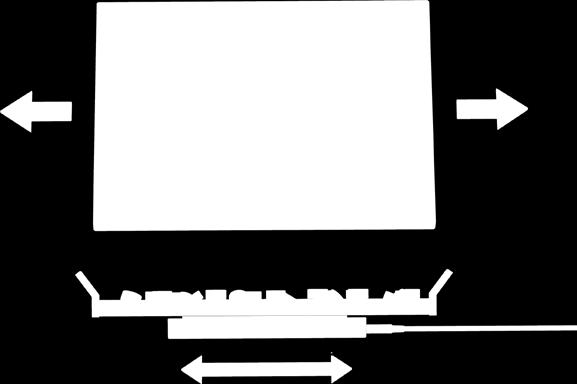
 Linear guide Permanent magnet Coil Rail Structure and Working Principle Linear encoder scale (Moving side) Table The permanent magnet is mounted on the bottom side of")
 of the permanent magnet on the left and repels the north pole on the right, and these attracting and repelling forces generate the thrust force.")
2 Card Motor Compact and lightweight Model LAT3-10 LAT3-20 LAT3-30 W (mm) 50 L (mm) W H (mm) 9 Weight (g) Cable Mounting The cable connector does not protrude above the actuator. Table Connector Actuator cable Card Motor Dowel pin holes for locating the workpiece Four tapped holes for mounting the workpiece L Dowel pin holes for locating the actuator body Four tapped holes for mounting the actuator body H Stopper (to prevent the table from separating from the actuator) Workpiece Mounting The table is provided with dowel pin holes for locating the workpiece as standard equipment. Body Mounting 2 body mounting options Workpiece mounting (Tapped holes) Two dowel pin holes for locating the workpiece Bottom mounting (Tapped holes) Two dowel pin holes for locating the actuator body Series Variations Model LAT3F LAT3 Stroke Sensor (Optical linear encoder) Resolution Linear motor Type 1.25 µm Moving magnetic 30 µm type linear motor Linear guide Type Linear guide with circulating balls Top mounting (Through hole) Pushing Maximum instantaneous thrust 5.2 N 6 N 5.5 N Positioning repeatability Accuracy ±5 µm ±90 µm Pushing measurement Accuracy ±10 µm ±100 µm Maximum load mass Horizontal Vertical 500 g 100 g 50 g Maximum speed 400 mm/s Linear encoder sensor head (Fixed side) Linear guide Permanent magnet Coil Rail Structure and Working Principle Linear encoder scale (Moving side) Table The permanent magnet is mounted on the bottom side of the table, and the coil is mounted on the top surface of the rail. When current is supplied to the coil, a north pole (N) is generated in the middle of the top surface of the coil. This north pole attracts the south pole (S) of the permanent magnet on the left and repels the north pole on the right, and these attracting and repelling forces generate the thrust force. Therefore, thrust force is applied to the table in the right direction, and the table moves to the right. When current is applied to the coil in the reverse direction, a south pole will be generated in the middle of the top surface of the coil. Similarly, a thrust force will be applied to the table in the left direction, and the table moves to the left. Force Permanent magnet Moves in the Table right direction Rail Moves in the left direction S S N S N N Coil Force 1


3 Series LAT3 Start-up time is reduced greatly with a system that is ready-to-use and easy to set up. The functions described below makes the start-up quick and easy. Parallel input/output status check function The status of the parallel input signals can be checked, or the parallel output signals can be activated manually using a PC. CN3 Parallel input/output signals CN5 PLC PC Built-in operation patterns Positioning operation (Absolute Relative) Speed Current position Positioning time Speed entry method Cycle time entry method Target position Absolute:The table moves to the target position with reference to the origin position and stops there. Relative :The table moves to the target position with reference to the current position and stops there. Controller Cycle time entry method Only target position and positioning time need to be entered, so there is no need to enter the speed, acceleration and deceleration. (Using the speed entry method allows you to enter the speed, acceleration and deceleration.) Step data input The Card Motor operation type and condition are preset in the step data. The Card Motor is operated according to the contents of the selected preset step data number. Pushing operation (Absolute Relative) Speed Speed entry method Cycle time entry method Low speed Pushing Selection of operation type Operating condition Positioning time Target position Step data The table moves to a position close to the target position, decelerates to low speed and starts pushing after the table has come in contact with the workpiece. Function for measuring and differentiation of workpieces The size of the workpiece can be measured based on the table stopping position by driving the table until it comes into contact with the workpiece. The workpieces can be differentiated or checked for quality using parallel output signals that correspond to preset table position ranges. Furthermore, using the multi-counter (optional accessory:refer to page 35) A B makes it possible to display the table position and output up to 31 preset points. A B PLC 2


4 Card Motor Application Examples of Card Motor The applications described below are just a few examples. When using the Card Motor, select an appropriate model by carefully checking the specifications. Examples of positioning applications Sensor head movement and positioning Component movement and positioning Electronic component pick and place Component supply to tape Component separation (escapement) Workpiece alignment Examples of measurement applications Measurement of workpiece height Measurement of glass substrate thickness (multiple points) Measurement of cable outside diameter Measurement of tape thickness 3


5 Series LAT3 Examples of high frequency actuation Alignment of components on pallet by vibration Distribution of workpieces Examples of pushing applications Pushing of workpieces (soft touch) Positioning of workpieces Cutting of resin mold component runners Tape alignment Switch inspection High-density layout 4
6 Series LAT3 Model Selection 1 Selection Procedure for Positioning Operation (Refer to pages 7 and 8 for Fig.1, 2, 3, 4, 5 and Table 1, 2, 3.) Selection Procedure Formula/Data Selection Example 1 Operating conditions List the operating conditions with consideration to the mounting orientation and shape of the workpiece. Select an actuator temporarily. 2 Select a model temporarily based on the required positioning repeatability and stroke. 3 Check the load mass and load factor. Find the allowable load mass Wmax [g] from the graph. *Confirm that the applied load mass W [g] does not exceed the allowable load mass. From Table 1, find the correction values for the distances to the moment center. Calculate the static moment M [N m]. From Table 3, find the allowable moment Mmax [N m]. Calculate the load factor αn for the static moments. *Confirm that the total sum of the guide load factors for the static moments does not exceed 1. Stroke St [mm] Load mass W [g] Mounting orientation Mounting angle θ [ ] Fig.2 Amount of overhang Ln [mm] Fig.1 Correction values for the distances to the moment center An [mm] Fig.1 Table 1 Positioning time Tp [ms] Positioning repeatability [μm] Table 2 An Fig.2 Table 1 M = W/ (Ln + An)/1000 Mmax Table 3 α = M/Mmax Σαp + αy + αr 1 15 mm 200 g Horizontal table mounting θ = 0 L1 = 10 mm L2 = 30 mm L3 = 35 mm Tp = 200 ms 100 μm Allowable load mass Wmax [g] L3 (Horizontal) Mounting angle θ [ ] From Table 1, A1 = 32.5 L2 + A2 A1 + L1 From Table 2, temporarily select the LAT3-20, which satisfies the positioning repeatability 100 μm and the minimum stroke that satisfies the stroke St = 15 Model LAT3-10 LAT3F-10 LAT3-20 LAT3F-20 LAT3-30 LAT3F-30 Stroke [mm] Positioning repeatability [μm] ±90 ±5 ±90 ±5 ±90 ±5 Wmax W Wmax From Fig. 2: θ = 0, find Wmax = 500 As W = 200 < Wmax = 500, the selected model can be used (Vertical) Pitch moment Mp = 200/1000 x 9.8 ( )/1000 = From Table 3, Mpmax = 0.3 αp = 0.044/0.3 = 0.15 Roll moment Mr = 200/1000 x 9.8 x 35/1000 = From Table 3, Mrmax = 0.2 αr = 0.069/0.2 = 0.35 Σαn = = 0.5 1, thus, the selected model can be used. 5 4 Check the positioning time. Find the shortest positioning time Tmin [ms] from the graph. *Confirm that the positioning time Tp [ms] is longer than the shortest positioning time. Tmin Fig.3 Tp Tmin From Fig. 3: St = 15 and W = 200, find Tmin = 130 As Tp = 200 Tmin = 130, the selected model can be used. Shortest positioning time Tmin [ms] W = Stroke(Positioning distance) St [mm]
7 L2 + A2 Model Selection Series LAT3 Selection Procedure for Pushing Operation Selection Procedure Formula/Data Selection Example 1 Operating conditions List the operating conditions with consideration to the mounting orientation and shape of the workpiece. *When operating the product in a vertical direction, consider the effect of the table weight on the Card Motor (See Table 2) and the weight of the workpiece to find out the pushing force of the Card Motor. Select an actuator temporarily. 2 Select a model temporarily based on the required measuring accuracy and stroke. 3 Check the load mass and moment. Find the allowable load mass Wmax [g] from the graph. *Confirm that the applied load mass W [g] does not exceed the allowable load mass. From Table 1, find the correction values for the distances to the moment center. Calculate the static moment M [N m]. From Table 3, find the allowable moment Mmax [N m]. Calculate the load factor αn for the static moments. *Confirm that the total sum of the guide load factors for the static moments does not exceed 1. Stroke St [mm] Load mass W [g] Mounting orientation Mounting angle θ [ ] Amount of overhang (L1, L2, L3) [mm] Fig.1 Correction values for the distances to the moment center An [mm] Fig.1 Table 1 Measuring accuracy [µm] Positioning time Tp [ms] Pushing force F [N] Pushing position [mm] Pushing direction Positioning time + Pushing time Ta [s] Cycle time Tb [s] Table 2 An Fig.2 Table 1 M = W/ (Ln + An)/1000 Mmax Table 3 α = M/Mmax Σαp + αy + αr 1 8 mm 50 g Horizontal table mounting θ = 0 L1 = 30 mm L2 = 10 mm L3 = 0 mm 10 μm Tp = 150 ms 4 N 4 mm Pushing direction away from the connector 4 s 10 s L1 + A1 From Table 2, temporarily select the LAT3F-10, which satisfies the measuring accuracy 10 μm and the minimum stroke that satisfies the stroke St = 8 Model LAT3-10 LAT3F-10 LAT3-20 LAT3F-20 LAT3-30 LAT3F-30 Stroke [mm] Measuring accuracy [μm] Wmax W Wmax From Fig. 2: θ = 0, find Wmax = 500 As W = 50 < Wmax = 500, the selected model can be used. From Table 1, A1 = 22.5 Pitch moment Mp = 50/1000 x 9.8 ( )/1000 = From Table 3, Mpmax = 0.2 Σαn = 0.13 αp = 0.026/0.2 = 0.13 L3 1, thus, the selected model can be used. 4 5 Check the positioning time. Find the shortest positioning time Tmin [ms] from the graph. *Confirm that the positioning time Tp [ms] is longer than the minimum positioning time. Check the pushing force. Calculate the duty ratio [%]. Find the allowable thrust setting value from the graph. From Fig. 5, find the allowable pushing force Fmax [N] generated at the required pushing position and for the allowable thrust setting value. Confirm that the pushing force F [N] does not exceed the allowable pushing force. Tmin Fig.3 Tp Tmin Duty ratio = Ta/Tb x 100 Fig.4 F Fmax Time while pushing force is applied Position Time Ta Tb From Fig. 3: St = 8 and W = 50, find Tmin = 100 As Tp = 150 Tmin = 100, the selected model can be used. Duty ratio = 4/10 x 100 = 40% From Fig. 4: LAT3-10 and 40% duty ratio, find the allowable thrust setting value = 4.2 Allowable thrust setting value 6 5 LAT Duty ratio [%] From Fig. 5: LAT3-10, pushing direction away from the connector at pushing position 4 mm, find Fmax = 4.5 As F = 4 Fmax = 4.5, the selected model can be used. 6
8 Series LAT3 Model Selection 2 Selection Caution 1. The temperature increase of the Card Motor varies depending on the duty ratio and the heat dissipation properties of the base it is mounted onto. If the temperature of the Card Motor becomes high, reduce the duty ratio by increasing the cycle time, or improve the heat transfer properties of the mounting base and the surroundings. 2. The pushing force generated by the Card Motor varies in relation to the thrust setting value depending on the pushing position and the pushing direction. Refer to Fig. 5 for details. Fig. 1 Amount of Overhang: Ln [mm], Correction Value for the Distances to the Moment Center: An [mm] Mounting orientation Mp: Pitching My: Yawing Mr: Rolling L1 A1 L1 A1 Mr L2 A2 Table 1Correction Value for the Distances to the Moment Center: An [mm] Model A1 A2 LAT LAT LAT Horizontal Mp My W W W L3 Mr W L2 A2 L3 Vertical Mp My W W Fig. 2 Allowable Load Mass: Wmax [g] Allowable load mass Wmax [g] Card Motor Mounting angle θ Load Movement direction 200 LAT3-10, LAT (Horizontal) Mounting angle θ [ ] (Vertical) Fig. 3 Shortest Positioning Time: Tmin [ms] (These are only reference values.) LAT3- LAT3F- Shortest positioning time Tmin [ms] Load mass W = 500 W = 400 W = 300 W = 0 W = 200 W = Stroke (Positioning distance) St [mm] Frequency [cpm] Operating conditions Model: LAT3- Mounting orientation: Horizontal/Vertical Step data input version: Cycle time entry method (Triangular movement profile) 7 Shortest positioning time Tmin [ms] Load mass W = 500 W = 400 W = W = W = 0 W = Stroke(Positioning distance) St [mm] 600 Frequency [cpm] Operating conditions Model: LAT3F- Mounting orientation: Horizontal/Vertical Step data input version: Cycle time entry method (Triangular movement profile) Fig. 4 Allowable Thrust Setting Value Allowable thrust setting value LAT3-10 LAT3-20 LAT Duty ratio Duty [%]
9 Model Selection Series LAT3 Fig.5 Pushing force: F [N] characteristics (Reference) Pushing direction away from the connector Pushing force [N] Pushing force [N] Connector side Thrust setting value: 5 Thrust setting value: 3 Thrust setting value: Pushing position [mm] Thrust setting value: 5 Thrust setting value: 3 Thrust setting value: Pushing position [mm] Pushing force Opposite side of the connector LAT3-10 LAT3-20 LAT3-30 Pushing direction toward the connector Pushing force Connector side Opposite side of the connector Operating conditions Mounting orientation: Horizontal table mounting Thrust setting value: Minimum, continuous, instantaneous maximum of each model. Pushing force [N] Pushing force [N] Thrust setting value: 4.8 Thrust setting value: 2.8 Thrust setting value: Pushing position [mm] Operating conditions Mounting orientation: Horizontal table mounting Thrust setting value: Minimum, continuous, instantaneous maximum of each model. LAT3-10 LAT3-20 LAT3-30 Thrust setting value: 4.8 Thrust setting value: 2.8 Thrust setting value: Pushing position [mm] Table start position: Retracted end (Connector side) Pushing direction: Away from the connector Pushing position: Positioning distance from the connector side, retracted end Pushing force [N] Pushing force [N] Thrust setting value: 3.9 Thrust setting value: 2.6 Thrust setting value: Pushing position [mm] Table start position: Extended end (Opposite side of the connector) Pushing force direction: Toward the connector Pushing position: Positioning distance from the connector side, retracted end Thrust setting value: 3.9 Thrust setting value: 2.6 Thrust setting value: Pushing position [mm] Table Displacement (Reference) Displacement through the entire stroke when a load is applied to the point indicated by the arrow Table displacement due to pitch moment load 40 A1 Table displacement due to yaw moment load 40 A1 Table displacement due to roll moment load 40 LAT3-10, -20, -30 LAT3-10, -20, -30 LAT3-10, -20, -30 Table displacement [mm] Load N Table displacement [mm] Load N Table displacement [mm] Table 2 Stroke: St [mm], Positioning Repeatability [µm], Measuring Accuracy [µm], Table Weight [g] Table 3 Allowable Moment: Mmax [N m] Model LAT3-10 LAT3F-10 LAT3-20 LAT3F-20 LAT3-30 LAT3F-30 Stroke [mm] Positioning repeatability [μm] ±90 ±5 ±90 ±5 ±90 ±5 Measuring accuracy [μm] Table weight [g] Load N Model Pitch moment/yaw moment Roll moment Mpmax, Mymax Mrmax LAT LAT LAT
10 Card Motor Controller Series LATCA/LATC4 System Construction/General Purpose I/O Provided by customer PLC VCard Motor Series LAT3 Power supply for I/O signal 24 VDC Note) Actuator cable (Option)V LATH1-m VCard motor controller (Option) To CN5 VI/O cable (Option) Controller type LATCA LATC4 Part no. LATH5-m LATH2-m To CN4 Counter plug (Accessory) To CN3 To CN2 Provided by customer Controller power supply 24 VDC Note) Note) When conformity to UL is required, the electric actuator and controller should be used with a UL1310 Class 2 power supply. To CN1 VPower supply plug (Accessory) <Applicable cable size> AWG20 (0.5 mm 2 ) LATCA/LATC4 Separately sold products Controller setting software Communication cablev VCounter cable* LATH3-m PC (Provided by customer) VController setting kit Controller type LATCA LATC4 Part no. LATC-W2 LATC-W1 Conversion unit VUSB cable (A-mini B type) Contents qcontroller setting software wcontroller setting cable (Communication cable, Conversion unit, USB cable) Note) Note) Communication cable and the conversion unit are integrated in the LATC-W2. VMulti-counter CEU5 Power supply for Multi-counter 24 VDC/100 VAC * Option: Can be ordered in the How to Order for the Card Motor. * Accessory: Attached to the controller * Separately sold products: Order separately. Refer to pages 34 to 36 for details. 9
 Controller type LATCA Part no.")
11 Card Motor Controller Series LATCA System Construction/Pulse Signal Provided by customer PLC VCard Motor Series LAT3 Power supply for I/O signal 24 VDC Note) VCard motor controller (Option) VI/O cable (Option) Controller type LATCA Part no. LATH5-m Actuator cable (Option)V LATH1-m To CN5 To CN4 Counter plug (Accessory) To CN3 To CN2 Provided by customer Controller power supply 24 VDC Note) Note) When conformity to UL is required, the electric actuator and controller should be used with a UL1310 Class 2 power supply. To CN1 VPower supply plug (Accessory) <Applicable cable size> AWG20 (0.5 mm 2 ) LATCA Separately sold products Controller setting software Communication cablev VCounter cable* LATH3-m PC (Provided by customer) VController setting kit Controller type LATCA Part no. LATC-W2 VUSB cable (A-mini B type) Contents qcontroller setting software wcontroller setting cable (Communication cable, Conversion unit, USB cable) Note) VMulti-counter CEU5 Power supply for Multi-counter 24 VDC/100 VAC * Option: Can be ordered in the How to Order for the Card Motor. * Accessory: Attached to the controller * Separately sold products: Order separately. Refer to pages 34 to 36 for details. 10
 Controller setting software Separately sold products VUSB cable (A-mini B type) PLC or PC (Provided by customer) Communication cablev RS485 Original protocol VController setting kit Controller type")
 VCommunication cable (Separately sold product) LATH6-m VCard motor controller")
12 Card Motor Controller Series LATCA System Construction/Serial Communication (One controller) Provided by customer Master equipment (PLC etc.) Controller setting software Separately sold products VUSB cable (A-mini B type) PLC or PC (Provided by customer) Communication cablev RS485 Original protocol VController setting kit Controller type LATCA Part no. LATC-W2 Contents qcontroller setting software wcontroller setting cable (Communication cable, Conversion unit, USB cable) VCommunication cable (Separately sold product) LATH6-m VCard motor controller (Option) Counter plug (Accessory) To CN4 To CN3 To CN3 To CN2 Provided by customer Controller power supply 24 VDC Note) Note) When conformity to UL is required, the electric actuator and controller should be used with a UL1310 Class 2 power supply. To CN1 VPower supply plug (Accessory) <Applicable cable size> AWG20 (0.5 mm 2 ) LATCA VActuator cable (Option) LATH1-m VCard Motor Series LAT3 * Option: Can be ordered in the How to Order for the Card Motor. * Accessory: Attached to the controller * Separately sold products: Order separately. Refer to pages 34 to 36 for details. 11

 LEC-CG2-m VBranch connector (Separately sold product) LEC-CGD VTerminating")
 LATCA Counter plug (Accessory) To CN4 To CN4 Up to 16 controllers are")
 Note) When conformity to UL is required, the electric actuator and controller should be used with a")
 Actuator cable (Option)V LATH1-m To CN1 VPower supply plug (Accessory) <Applicable cable size> AWG20")
 VCard Motor Series LAT3 * Option: Can be ordered in the How to Order for the Card Motor.")
13 Card Motor Controller Series LATCA System Construction/Serial Communication (2 to 16 controllers) Provided by customer Master equipment (PLC etc.) PLC RS485 Original protocol BranchV communication cable (Separately sold product) LATH7-m VCable between branches (Separately sold product) LEC-CG2-m VBranch connector (Separately sold product) LEC-CGD VTerminating resistor connector (Separately sold product) LEC-CGR Communication cablev (Separately sold product) LEC-CG1-m VCard motor controller (Option) LATCA Counter plug (Accessory) To CN4 To CN4 Up to 16 controllers are connectable To CN4 To CN3 To CN2 To CN3 To CN2 To CN3 To CN2 Provided by customer Controller power supply 24 VDC Note) Note) When conformity to UL is required, the electric actuator and controller should be used with a UL1310 Class 2 power supply. To CN1 VPower supply plug (Accessory) <Applicable cable size> AWG20 (0.5 mm 2 ) Actuator cable (Option)V LATH1-m To CN1 VPower supply plug (Accessory) <Applicable cable size> AWG20 (0.5 mm 2 ) To CN1 VPower supply plug (Accessory) <Applicable cable size> AWG20 (0.5 mm 2 ) VCard Motor Series LAT3 * Option: Can be ordered in the How to Order for the Card Motor. * Accessory: Attached to the controller * Separately sold products: Order separately. Refer to pages 34 to 36 for details. 12
 DIN rail mounting Note 1) Controller Nil")
14 Card Motor Series LAT3 RoHS How to Order LAT3 10 Sensor resolution Nil 30 μm F 1.25 μm Stroke mm mm mm Actuator cable length Nil Without cable 1 1 m 3 3 m 5 5 m 1 N 1 D Controller mounting Nil Screw mounting D Note 3) DIN rail mounting Note 1) Controller Nil Without controller N With controller LATC4 (NPN) P With controller LATC4 (PNP) AN With controller LATCA (NPN) AP With controller LATCA (PNP) Note 2) I/O cable length Nil Without cable 1 1 m 3 3 m 5 5 m Note 1) Refer to pages 15 (LATCA) and 23 (LATC4) for detailed specifications of the controller. Note 2) If Without controller has been selected, the I/O cable is also not included. Therefore it is not possible to select the I/O cable for this option. If the I/O cable is required, please order separately. (Refer to page 33, [I/O cable] for details.) When controller LATC4 is selected, I/O cable LATH2 is supplied. When controller LATCA is selected, I/O cable LATH5 is supplied. Note 3) The DIN rail is not included. If the DIN rail is required, please order separately. (Refer to page 16, DIN rail and DIN rail mounting adapter for details.) Specifications 13 Model LAT3-10 LAT3F-10 LAT3-20 LAT3F-20 LAT3-30 LAT3F-30 Stroke (mm) Type Moving magnet type linear motor Motor Maximum instantaneous thrust (N) Note 1) 2) 3) Continuous thrust (N) Note 1) 2) 3) Guide Type Linear guide with circulating balls Maximum load mass (g) Horizontal: 500, Vertical: 100 Horizontal: 500, Vertical: 50 Type Optical linear encoder (incremental) Sensor Resolution (μm) Origin position signal None Provided None Provided None Provided Pushing Pushing speed (mm/s) 6 operation Thrust setting value Note 1) 2) 3) 1 to 5 1 to to 3.9 Positioning operation Positioning Note 4) 5) ±90 ±5 ±90 ±5 ±90 ±5 repeatability (μm) Measurement Accuracy (μm) Note 4) 5) ±100 ±10 ±100 ±10 ±100 ±10 Maximum speed (mm/s) Note 6) 400 Operating temperature range ( C) 5 to 40 (No condensation) Operating humidity range (%) 35 to 85 (No condensation) Weight (g) Note 7) Table weight (g) Note 1) Continuous thrust can be generated and maintained continuously. Maximum instantaneous thrust is the maximum peak thrust that can be generated. Refer to Fig. 4 Allowable thrust setting value (Page 7) and to Fig. 5 Pushing force characteristics (Page 8). Note 2) When mounted on a base with good heat dissipating capacity at 20 C ambient temperature. Note 3) The pushing force varies depending on the operating environment, pushing direction and table position. Refer to Fig. 5 Pushing force characteristics (Page 8). Note 4) When the temperature of the Card Motor is 20 C. Note 5) The accuracy after mounting the Card Motor may vary depending on the mounting conditions, operating conditions and environment, so please calibrate it with the equipment used in your application. Note 6) The maximum speed varies depending on the operating conditions (load mass, positioning distance). Note 7) The weight of the Card Motor itself. Controllers and cables are not included.
15 Card Motor Series LAT3 Dimensions LAT3 - (Rail dowel pin hole) E Stroke: A G 20±0.1 Note 2) ø3 0 depth 1.5 Table dowel pin hole (Fix this part of the cable.) (R43) (Table width) 32 Rail Table H B D Minimum cable bending radius ø Note 2) depth 1.5 Actuator cable Note 1) C x M3 x 0.5 depth 2.5 Table mounting screw hole F Note 1) 4 x M3 x 0.5 depth 2 Rail mounting screw hole 24 Note 2) ø3 0 depth 2 Rail dowel pin hole 16 32± Note 2) depth 2 Note 1) Refer to page 38 regarding Specific Product Precautions for the mounting screws. Note 2) The length of the part of the dowel pin inserted into the positioning hole should be shorter than the specified depth. Note 3) This drawing shows the origin position. Note 4) The origin positions G and H are reference dimensions (guide). Refer to page 32 for details on the origin position. (mm) Model Stroke Table dimensions Rail dimensions Origin position Note 4) A B C D E F G H LAT LAT LAT
16 Card Motor Controller (Step Data Input Type/Pulse Input Type) Series LATCA RoHS How to Order LATCA N Controller for the Card Motor Parallel I/O type N NPN P PNP Note 1) I/O cable LATH5-m is supplied. The actuator cable, the counter cable and the controller setting cable are not supplied with the controller. Refer to pages 33 to 36 for options. Note 2) The DIN rail is not included. If the DIN rail is required, please order separately. (Refer to page 16.) Option Nil Screw mounting D Note 2) DIN rail mounting I/O cable (with shield) length Nil Without cable 1 1 m 3 3 m 5 5 m Note 1) Specifications Model LATCA Setting method Note 1) Step data input type Pulse input type Compatible actuator Number of axis Card Motor series LAT3 Power supply Note 2) Power supply voltage: 24 VDC ±10%, Current consumption Note 3) : Rated 2 A (Peak 3 A), Power consumption Note 3) : 48 W (Maximum 72 W) Control system Movement modes Note 1) Either the step data input type or pulse input type can be selected after purchase. Note 2) Do not use a power supply of inrush current limited type for the controller. Note 3) Rated current: Current consumption when continuous thrust is generated. Peak current: Current consumption when maximum instantaneous thrust is generated. Note 4) Specification for the connection of the separately sold multi-counter (CEU5). Note 5) Cables are not included. Note 6) This setting software is not supplied with the controller. Order it separately (refer to page 36 for details). Note 7) Setup cable is included with the controller setting kit. 1 axis Closed loop Positioning operation, Pushing operation Number of step data 15 points 4 points Parallel input Parallel output Pulse input mode Pulse signal input maximum frequency Note 4) Position display output A-phase Serial Communication LED indicator Cooling method Operating temperature range Operating humidity range Insulation resistance Note 5) Weight Screw Note 6) Controller setting kit LATC-W2 Note 7) Setup cable LEC-W2-C, 15 6 inputs (Optically isolated) 4 outputs (Optically isolated, open collector output) Pulse and direction control mode CW and CCW control mode Quadrature control mode 100 khz (Open collector) 200 khz (Differential) and B-phase pulse signals, RESET signal (NPN open collector output) RS485 (Original protocol) 2 LED s (Green and Red) Natural air-cooling 0 to 40 C (No condensation) 90% or less (No condensation) Between case and FG: 50 MΩ (500 VDC) mounting: 130 g, DIN rail mounting: 150 g LEC-W2-U (Same cable as included with LEC-W2)
17 Controller Series LATCA How to Mount a) Screw mounting (LATCA- ) (Installation with two M4 screws) b) DIN rail mounting (LATCA- D) (Installation with the DIN rail) DIN rail is locked. Mounting direction Ground wire Ground wire Ground wire DIN rail Mounting direction A DIN rail mounting adapter Hook the controller on the DIN rail and press the lever of section A in the arrow direction to lock it. DIN rail AXT100-DR- L 12.5 (Pitch) *For, enter a number from the No. line in the table below. Refer to the dimensions on page 17 for the mounting dimensions. L Dimension 5.5 (35) (25) 8 (1.5) No L No L DIN rail mounting adapter LEC-D0 (with 2 mounting screws) The DIN rail mounting adapter can be retrofitted onto a screw mounting type controller. 16
18 Series LATCA Dimensions a) Screw mounting (LATCA- ) Power supply LED (Green) When the LED is lit: Power When the LED is flashing: Alarm Alarm LED (Red) (When the LED is lit or flashing: Alarm) ø4.5 for body mounting CN5: Parallel I/O connector CN4: Counter connector CN3: Serial I/O connector CN2: Motor connector CN1: Power supply connector 4.6 for body mounting b) DIN rail mounting (LATCA- D) Refer to page 16 for L dimension and part number of DIN rail (81.7) 66 1 (11.5) (When the DIN rail mounting adapter is in unlocked position) (When the DIN rail mounting adapter is in locked position) (91.7) Note) When two or more controllers are used, the space between the controllers should be 10 mm or more. 17
19 Controller Series LATCA Wiring Example Power Supply Connector: CN1 Power Supply Connector Terminal Terminal name Function Details DC1 ( ) DC1 (+) Counter Connector: CN4 Counter Connector Terminal Parallel I/O Connector: CN5 NPN Power supply ( ) Power supply (+) The power supply plug is an accessory (supplied with the controller). Use an AWG20 (0.5 mm 2 ) cable for connecting the power supply plug to a 24 VDC power supply. The negative ( ) power supply terminal to the controller. Power ( ) is also supplied to the Card Motor via the internal circuit of the controller and actuator cable. The positive (+) power supply terminal to the controller. Power (+) is also supplied to the Card Motor via the internal circuit of the controller and actuator cable. The counter plug is an accessory (supplied with the controller). Use the counter cable (LATH3- ) for connecting the counter to the counter plug. Name Details Cable color PhaseB Connect to the phase B wire of the counter cable. White PhaseA Connect to the phase A wire of the counter cable. Red GND Connect to the GND wire of the counter cable. Light gray RESET Connect to the Reset wire of the counter cable. Yellow FG Connect to the FG wire of the counter cable. Green DC1( ) DC1(+) Power supply plug PhaseB PhaseA GND RESET FG Counter plug Use the I/O cable (LATH5- ) to connect a PLC, etc., to the CN5 parallel I/O connector. The wiring is specific to the type of parallel I/O (NPN or PNP). Please refer to the wiring diagrams below for correct wiring of NPN and PNP type controllers. PNP CN5 A1 24 VDC power supply for the input signals CN5 A1 24 VDC power supply for the input signals A2 A2 A3 A4 A5 A6 The power supply can be either polarity. A3 A4 A5 A6 The power supply can be either polarity. A7 A7 Main circuit Internal resistance 10 [kω] A8 A9 A10 B1 B2 24 VDC power supply for the output signals Main circuit Internal resistance 10 [kω] A8 A9 A10 B1 B2 24 VDC power supply for the output signals B3 B3 B4 B4 Pulse input internal circuit B5 B6 B7 B8 B9 B10 Maximum output current 10 ma Pulse input circuit Pulse input internal circuit B5 B6 B7 B8 B9 B10 Maximum output current 10 ma Pulse input circuit Note) When using the controller by the step data input type, do not wire as there is an internal circuit to use terminals B7 to B10 as the pulse signal input terminals. 18
20 Series LATCA Wiring Example Input/Output Signal Terminal no. Input/Output Function Details A1 COM Connect a 24 VDC power supply for the input signals. (Polarity is reversible) A2 IN0 Selection of step data number A3 IN1 specified by a Bit No. A4 IN2 (combinations of IN0 to IN3) A5 IN3 Input A6 DRIVE Command to drive the motor A7 SV Command to turn the servo motor A8 NC Not connected A9 NC Not connected A10 NC Not connected B1 DC2 (+) Connect the 24 V power supply terminal for the output signals. B2 DC2 ( ) Connect the 0 V power supply terminal for the output signals. B3 BUSY when the actuator is moving Note 1) Output B4 ALARM when an alarm has been generated Note 2) B5 OUT0 Select an output function among BUSY, INP, B6 OUT1 INFP, INF, AREA A and AREA B. Note 3) B7 NC Not connected B8 NC Not connected Input B9 NC Not connected B10 NC Not connected Note 1) Other output functions can also be assigned to the BUSY output. Note 2) This output signal turns when power is supplied to the controller, but turns in alarm condition (N.C.). Note 3) INP is set as a default for OUT0, and INF for OUT1. Pulse Input Type Input/Output Signal Terminal no. Input/Output Function Details A1 COM Connect a 24 VDC power supply for the input signals. (Polarity is reversible) A2 IN0 Selection of step data number specified by a Bit No. A3 IN1 (combinations of IN0 and IN1) A4 SETUP Instruction to return to origin A5 CLR Deviation reset Input A6 TL Instruction to pushing operation A7 SV Command to turn the servo motor A8 NC Not connected A9 NC Not connected A10 NC Not connected B1 DC2 (+) Connect the 24 V power supply terminal for the output signals. B2 DC2 ( ) Connect the 0 V power supply terminal for the output signals. B3 BUSY when the actuator is moving Note 1) Output B4 ALARM when an alarm has been generated Note 2) B5 OUT0 Select an output function among BUSY, INP, B6 OUT1 INFP, INF, AREA A and AREA B. Note 3) B7 PP+ B8 PP Input B9 NP+ Connect the pulse input signal Note 4) B10 NP Note 1) Other output functions can also be assigned to the BUSY output. Note 2) This output signal turns when power is supplied to the controller, but turns in alarm condition (N.C.). Note 3) INP is set as a default for OUT0, and INF for OUT1. Note 4) The function assignment changes according to the pulse input mode. Pulse Input Circuit Example PP+ PP NP+ NP Step Data Input Type Pulse signal output of positioning unit is open collector output B7 B8 B9 B10 Pulse signal power supply (24 VDC or 5 V ) OUT0 and OUT1 Optional Output Functions Note) Name Details BUSY when the actuator is moving Note 1) when the table is within the INP output range INP of the current Target Position. when the table is within the positioning INFP repeatability range of the actuator for the current Target Position. when the pushing force is within the INF Threshold Force Value. AREA A, AREA B when the table is within the set Area Ranges. Note) One output function can be selected for each OUT0 and OUT1. Pulse Input Internal Circuit Pulse and direction control mode H PP L NP Main circuit R1 R2 R3 R1 R2 R3 CW and CCW control mode H PP L <No. 1> <No. 2> <No. 3> <No. 4> <No. 5> <No. 6> Counts by L Pulse train input signal switch Counts by L B7 B8 B9 B10 Signal input method Pulse input signal power supply voltage Pulse input signal input switch setting Current limit resistor R specifications (a) Open 24 VDC ±10% No. 2 & No. 5:, Others: R2 = 1.5 kω (b) collector input 5 VDC ±5% No. 1 & No. 4:, Others: R1 = 220 Ω (c) Differential input No. 3 & No. 6:, Others: R3 = 120 Ω (a) Open collector input (24 V) (b) Open collector input (5 V) (c) Differential input (24 V) Change the switch in the controller according to the pulse input signal power supply voltage. Pulse Input Mode Table moves to opposite side of connector Table moves to connector side Pulse signal output of positioning unit is differential output PP+ PP NP+ NP 19 B7 B8 B9 B10 NP Quadrature control mode H PP L NP Counts by H and L
21 Controller Series LATCA Signal Timing Return to Origin The SV input turns after the ALARM output has turned. The controller scans the step data number. Power supply IN0 to 3 Input SV DRIVE BUSY 24 V 0 V Caution Use a 2 msec interval or more between input signals, and maintain the signal state for at least 2 msec. Turn the SV signal first after that the ALARM signal has turned after power has been supplied to the controller. If the SV signal is already, the operation will not start for safety reasons. Keep the DRIVE signal turned until the next operation instruction is given except when stopped during operation. When the DRIVE signal is turned during positioning operation, the table of the Card Motor stops, and holds the position. When the DRIVE signal is turned during pushing operation, the pushing operation is completed and this position is retained. Output OUT0 (INP) ALARM Speed 0 mm/s Return to origin The Alarm output turns after the controller has been initialized. The INP output turns after the return to origin has been completed. ALARM is expressed as negative-logic circuit. Positioning Operation Set the step data no. The controller scans the step data number. Pushing Operation Set the step data no. The controller scans the step data number. Power supply 24 V 0 V Power supply 24 V 0 V IN0 to 3 IN0 to 3 Input SV Input SV DRIVE DRIVE Output BUSY OUT0 (INP) Output BUSY OUT1 (INF) Speed Positioning operation 0 mm/s Speed Pushing operation 0 mm/s AREA Signal The INP output turns when the Card Motor table is within the INP output range of the "Target Position". The INP signal will turn again if the table moves outside the INP output range. The INF output turns when the pushing force exceeds the set "threshold" pushing force value. The INF signal turns when the DRIVE signal is turned. Table position Output AREA B (Position 2) AREA B (Position 1) AREA A (Position 2) AREA A (Position 1) AREA A AREA B * Select the AREA signal for the parallel output (OUT0 or OUT1). Alarm Reset Input Output SV ALARM Alarm out Alarm reset Remove the cause of the alarm. ALARM is expressed as negative-logic circuit. 20 A
22 Series LATCA Signal Timing (When pulse input type is selected) Return to Origin Power supply Input Output IN0 to 1 SV SETUP BUSY OUT0 (INP) ALARM SV input after ALARM output SETUP input after INP output 24 V 0 V Positioning Operation Set the step data no. Power supply Input Output IN0 to 1 SV PP NP BUSY OUT0 (INP) The controller scans the step data number. Start of pulse input 24 V 0 V Speed after controller system initialization ALARM is expressed as negative-logic circuit. Return to origin OUT0 (INP) and BUSY output after return to origin has been completed. 0 mm/s Speed Positioning operation 0 mm/s OUT0 (INP) output turns in the condition where the pulse input signal is not input for 10 ms or more continuously, and the deviation from the target value becomes the positioning width or less. Caution Turn the SV signal first after that the ALARM signal has turned after power has been supplied to the controller. If the SV signal is already, the operation will not start for safety reasons. During the return to origin, do not input a pulse input signal until the SETUP signal has turned. Pulse input signals input while the SETUP signal is turned will be invalidated. Do not input the pulse input signals PP and NP at the same time in the CW and CCW control mode. When changing the moving direction of the actuator, be sure to leave an interval of 10 [msec] or more, and input a pulse signal of reverse direction. After the IN0 and IN1 signals are changed, leave an interval of 10 ms or more, then input a pulse input signal. When the amount of movement is less than the following count, positioning control will not be performed. Input a pulse input signal that is equal to or more than the following count. LAT3 : 3 counts, LAT3F : 4 counts Pushing Operation Set the step data no. Power supply Input The controller scans the step data number. IN0 to 1 SV PP NP TL Start of pulse input 24 V 0 V Operation after Pushing Operation Power supply Input IN0 to 1 SV PP NP TL Set the step data no. The controller scans the step data number. 24 V 0 V Output BUSY OUT0 (INP) OUT1 (INF) Output BUSY OUT0 (INP) OUT1 (INF) OUT0 (INP) output is always when TL signal is. Speed 6 mm/s 0 mm/s Speed Pushing operation Positioning operation 0 mm/s When TL input turns, the speed slows down to 6 mm/s (Pushing operation start). AREA Signal Table position Output AREA B (Position 2) AREA B (Position 1) AREA A (Position 2) AREA A (Position 1) AREA A AREA B OUT1 (INF) output turns when the generated force exceeds the trigger LV of the INF signal. * Select the AREA signal for the parallel output (OUT0 or OUT1). 21 When TL input turns, OUT1 (INF) signal turns. Alarm Reset Input Output SV ALARM Alarm out When the target value by the pulse input signal conforms to the current location, the pushing operation ends and starts the positioning operation. Alarm reset Remove the cause of the alarm. ALARM is expressed as negative-logic circuit.
23 Controller Series LATCA Serial Communication Communication Specifications Item Protocol Communication data Node type Error checking Frame size Communication speed Data bit Communication method Parity Stop bit Flow control Note) Original (command method) is used as the protocol. Details Original Note) ASCII Slave (Controller) None Variable length: Max. 128 bytes RS485, asynchronous system 19,200 bps 8 bit Even parity 1 bit None Function qsetting of step data The contents of the step data such as the target position and positioning time can be set. wacquisition of operation information Information such as the status of a parallel I/O signal and table position can be acquired. estep data operation Without inputting a parallel I/O signal, the step data no. can be selected from the communication device of the PLC, etc. via serial communication to specify the operation. rdirect operation Operation can be executed by setting the target position, positioning time, etc. each time. Caution Use the controller setting software to set the basic settings (refer to the following) of the controller. 1. Select input type 2. Card motor product number 3. Method to return to origin 4. Step data input version 5. Card motor mounting orientation 6. Set the controller ID (Set to 1 at the time of shipment) 7. Select output signal 22
24 Card Motor Controller (Step Data Input Type) Series LATC4 RoHS How to Order LATC4 N Controller for the Card Motor Parallel I/O type N NPN P PNP Option Nil Screw mounting D Note 2) DIN rail mounting Note 1) I/O cable (without shield) length Nil Without cable 1 1 m 3 3 m 5 5 m Note 1) I/O cable LATH2- is supplied. The actuator cable, the counter cable and the controller setting cable are not supplied with the controller. Refer to pages 33 to 36 for options. Note 2) The DIN rail is not included. If the DIN rail is required, please order separately. (Refer to page 24.) Specifications Item Setting method Compatible actuator Number of axis LATC4 Step data input type Card Motor series LAT3 Power supply Note 1) Power supply voltage: 24 VDC ±10%, Current consumption: Rated 2 A (Peak 3 A) Note 2) Note 2), Power consumption: 48 W (Maximum 72 W) Control system Movement modes Number of step data Parallel input Parallel output Note 3) Position display output A-phase LED indicator Cooling method Operating temperature range Operating humidity range Insulation resistance Note 4) Weight Screw Note 5) Controller setting kit LATC-W1 Note 6) Setting cable LATC-W1P-020AS Note 1) Do not use a power supply of inrush current limited type for the controller. Note 2) Rated current: Current consumption when continuous thrust is generated. Peak current: Current consumption when maximum instantaneous thrust is generated. Note 3) Specification for the connection of the separately sold multi-counter (CEU5). Note 4) Cables are not included. Note 5) This setting software is not supplied with the controller. Order it separately (Refer to page 36 for details). Note 6) Setup cable is included with the controller setting kit axis Closed loop Positioning operation, Pushing operation 15 (Absolute or relative) 6 inputs (Optically isolated) 4 outputs (Optically isolated, open collector output) and B-phase pulse signals, RESET signal (NPN open collector output) 2 LED s (Green and Red) Natural air-cooling 5 to 40 C (No condensation) 35 to 85% (No condensation) Between case and FG: 50 MΩ (500 VDC) mounting: 130 g, DIN rail mounting: 150 g

 5.25 7.5 *For, enter a number from the No. line in the table below.")

25 Controller Series LATC4 How to Mount a) Screw mounting (LATC4- ) (Installation with two M4 screws) b) DIN rail mounting (LATC4- D) (Installation with the DIN rail) DIN rail is locked. Mounting direction Ground wire Ground wire Ground wire DIN rail Mounting direction A DIN rail mounting adapter Hook the controller on the DIN rail and press the lever of section A in the arrow direction to lock it. DIN rail AXT100-DR- L 12.5 (Pitch) *For, enter a number from the No. line in the table below. Refer to the dimensions on page 25 for the mounting dimensions. L Dimension 5.5 (35) (25) 8 (1.5) No L No L DIN rail mounting adapter LEC-D0 (with 2 mounting screws) The DIN rail mounting adapter can be retrofitted onto a screw mounting type controller. 24
26 Series LATC4 Dimensions a) Screw mounting (LATC4- ) Power supply LED (Green) When the LED is lit: Power When the LED is flashing: Alarm Alarm LED (Red) (When the LED is lit or flashing: Alarm) ø4.5 for body mounting CN5: Parallel I/O connector CN4: Counter connector CN3: Serial I/O connector CN2: Motor connector CN1: Power supply connector 4.6 for body mounting b) DIN rail mounting (LATC4- D) Refer to page 24 for L dimension and part number of DIN rail (81.7) 66 1 (11.5) (When the DIN rail mounting adapter is in unlocked position) (When the DIN rail mounting adapter is in locked position) (91.7) Note) When two or more controllers are used, the space between the controllers should be 10 mm or more. 25
27 Controller Series LATC4 Wiring Example Power Supply Connector: CN1 Power Supply Connector Terminal Terminal name Function Details DC1 ( ) DC1 (+) Power supply ( ) Power supply (+) Counter Connector: CN4 Counter Connector Terminal The power supply plug is an accessory (supplied with the controller). Use an AWG20 (0.5 mm 2 ) cable for connecting the power supply plug to a 24 VDC power supply. The negative ( ) power supply terminal to the controller. Power ( ) is also supplied to the Card Motor via the internal circuit of the controller and actuator cable. The positive (+) power supply terminal to the controller. Power (+) is also supplied to the Card Motor via the internal circuit of the controller and actuator cable. The counter plug is an accessory (supplied with the controller). Use the counter cable (LATH3- ) for connecting the counter to the counter plug. Name Details Cable color PhaseB Connect to the phase B wire of the counter cable. White PhaseA Connect to the phase A wire of the counter cable. Red GND Connect to the GND wire of the counter cable. Light gray RESET Connect to the Reset wire of the counter cable. Yellow FG Connect to the FG wire of the counter cable. Green DC1( ) DC1(+) Power supply plug PhaseB PhaseA GND RESET FG Counter plug Use the I/O cable (LATH2- ) to connect a PLC, etc., to the CN5 parallel I/O connector. Parallel I/O Connector: CN5 The wiring is specific to the type of parallel I/O (NPN or PNP). Please refer to the wiring diagrams below for correct wiring of NPN and PNP type controllers. NPN output circuit PNP output circuit Main circuit Internal resistance 10 [kω] Input Signal Name COM IN0 to IN3 DRIVE SV NC COM IN0 IN1 IN2 IN3 DRIVE SV NC NC NC DC2 (+) DC2 ( ) BUSY ALARM OUT0 OUT1 NC NC NC NC A1 A2 A3 A4 A5 A6 A7 A8 A9 A10 B1 B2 B3 B4 B5 B6 B7 B8 B9 B10 Load Load Load Load Details 24 VDC power supply for the input signals The power supply can be either polarity. 2 ma or more is needed for the input to be. 24 VDC power supply for the output signals Maximum output current 10 ma Connect a 24 VDC power supply for the input signals. (Polarity is reversible) Selection of step data number specified by a Bit No. (combinations of IN0 to IN3) Command to drive the motor Command to turn the servo motor Not connected Main circuit Internal resistance 10 [kω] COM IN0 IN1 IN2 IN3 DRIVE SV NC NC NC DC2 (+) DC2 ( ) BUSY ALARM OUT0 OUT1 NC NC NC NC A1 A2 A3 A4 A5 A6 A7 A8 A9 A10 B1 B2 B3 B4 B5 B6 B7 B8 B9 B10 Output Signal Name Details DC2 (+) Connect the 24 V power supply terminal for the output signals. DC2 ( ) Connect the 0 V power supply terminal for the output signals. BUSY when the actuator is moving Note 1) ALARM when an alarm has been generated Note 2) OUT0 Select an output function among BUSY, INP, OUT1 INFP, INF, AREA A and AREA B. Note 3) NC Not connected Note 1) Other output functions can also be assigned to the BUSY output. Note 2) This output signal turns when power is supplied to the controller, but turns in alarm condition (N.C.). Note 3) INP is set as a default for OUT0, and INF for OUT1. Load Load Load Load 24 VDC power supply for the input signals The power supply can be either polarity. 2 ma or more is needed for the input to be. 24 VDC power supply for the output signals Maximum output current 10 ma OUT0 and OUT1 optional output functions Note) Name Details when the actuator BUSY is moving Note 1) when the table is within the INP INP output range of the current "Target Position". when the table is within the INFP positioning repeatability range of the actuator for the current "Target Position". when the pushing force is INF within the Threshold Force Value. AREA A, when the table is within AREA B the set "Area Ranges". Note) One output function can be selected for each OUT0 and OUT1. 26
28 Series LATC4 Signal Timing Return to Origin Power supply IN0 to 3 Input SV DRIVE BUSY The SV input turns after the ALARM output has turned. The controller scans the step data number. 24 V 0 V Caution Use a 2 msec interval or more between input signals, and maintain the signal state for at least 2 msec. Turn the SV signal first after that the ALARM signal has turned after power has been supplied to the controller. If the SV signal is already, the operation will not start for safety reasons. Keep the DRIVE signal turned until the next operation instruction is given except when stopped during operation. When the DRIVE signal is turned during positioning operation, the table of the Card Motor stops, and holds the position. When the DRIVE signal is turned during pushing operation, the pushing operation is completed and this position is retained. Output OUT0 (INP) ALARM Speed 0 mm/s The Alarm output turns after the controller has been initialized. ALARM is expressed as negative-logic circuit. Return to origin The INP output turns after the return to origin has been completed. Positioning Operation Set the step data no. The controller scans the step data number. Pushing Operation Set the step data no. The controller scans the step data number. Power supply 24 V 0 V Power supply 24 V 0 V IN0 to 3 IN0 to 3 Input SV Input SV DRIVE DRIVE Output BUSY OUT0 (INP) Output BUSY OUT1 (INF) Speed Positioning operation 0 mm/s Speed Pushing operation 0 mm/s A AREA Signal Table position Output The INP output turns when the Card Motor table is within the INP output range of the "Target Position". The INP signal will turn again if the table moves outside the INP output range. AREA B (Position 2) AREA B (Position 1) AREA A (Position 2) AREA A (Position 1) AREA A AREA B * Select the AREA signal for the parallel output (OUT0 or OUT1). 27 Alarm Reset Input Output SV ALARM The INF output turns when the pushing force exceeds the set "threshold" pushing force value. The INF signal turns when the DRIVE signal is turned. Alarm out Alarm reset Remove the cause of the alarm. ALARM is expressed as negative-logic circuit.
29 Controller Series LATC Step Data Setting Methods and Movement Profiles There are two methods for setting the step data in the Card Motor controller as described below. Cycle time entry method Speed entry method To operate the table based on the target position and positioning time, or to operate it at high frequency. The speed, acceleration and deceleration are calculated automatically after the target position and positioning time have been set. To operate the table at a constant speed. The table moves to the set target position based on the set speed, acceleration and deceleration. Cycle Time Entry Method (Positioning Operation) Setting items: Target position [mm] Positioning time [s] Calculate the positioning distance S [mm] between the start position and the target position. The table will move to the target position based on the set positioning time tp [s] according to a triangular movement profile as shown in the diagram on the right. * It is not necessary to enter the speed, acceleration and deceleration since they are calculated automatically by the Card Motor Controller Setting Software. Load mass [g] Speed Vc Acceleration Aa Speed [mm/s] Positioning distance S Positioning time tp Time [s] The positioning time should be set longer than the shortest positioning time shown in Fig. 3 on page 7 with consideration to the load mass during the operation. If there is overshoot or vibration, set the positioning time longer. Speed Entry Method (Positioning Operation) Setting items: Target position [mm] Speed [mm/s] Acceleration [mm/s 2 ] Deceleration [mm/s 2 ] Load mass [g] Calculate the positioning distance S [mm] between the start position and the target position. The table will move to the target position based on the set speed Vc [mm/s], acceleration Aa [mm/s 2 ] and deceleration Ad [mm/s 2 ] according to a trapezoidal movement profile as shown in the diagram on the right. Refer to the equations below for how to calculate the acceleration, constant velocity and deceleration times and distances. Acceleration time: ta = Vc / Aa [s] Deceleration time: td = Vc / Ad [s] Acceleration distance: Sa = 0.5 x Aa x ta 2 [mm] Deceleration distance: Sd = 0.5 x Ad x td 2 [mm] Distance with constant velocity: Sc = S Sa Sd [mm] Time with constant velocity: tc = Sc / Vc [s] Positioning time: tp = ta + tc + td [s] (Add settling time to the positioning time to obtain the real cycle time.) *The settling time varies depending on the positioning distance and load mass seconds can be used as a reference value. The acceleration and deceleration should be smaller than the maximum acceleration/deceleration with consideration to the load mass during the operation as specified in the diagram on the right. Caution If the acceleration/deceleration is low, the table may not reach the set speed due to a triangular movement profile. Maximum acceleration/deceleration [mm/s 2 ] Speed [mm/s] 70,000 60,000 50,000 40,000 30,000 20,000 10,000 Acceleration Aa ta tc tp Card Motor LAT3-10 LAT3-20 LAT3-30 Speed Vc td Positioning distance S Deceleration Ad Time [s] Load mass [g] 28

![Cycle Time Entry Method Step 1 Basic settings Set each item described below and register it to the controller by clicking [Setup].](/docs-images/95/123598232/images/30-1.jpg "A [Card Motor Product Number]: Enter the product number of the connected Card Motor. B [Method to Return to Origin]: Select origin method and position.")
![C [Card Motor Mounting Orientation]: Select horizontal or vertical.](/docs-images/95/123598232/images/30-2.jpg "D [Step Data Input Version]: Select cycle time entry method A C B Step 3 <Positioning operation> Items to enter G Target position [mm] H I Positioning time [s] Load mass [g] <Pushing operation> Items")
![to enter G Target position [mm] H I Setting of the operating conditions -Entering of the operating values- Positioning time [s] Load mass [g] Distance from the origin position (or current position)](/docs-images/95/123598232/images/30-3.jpg "to the target position Time required to move to the target position Select the approximate weight of jigs or workpieces mounted on the Card Motor table.")
30 Series LATC Cycle Time Entry The controller automatically calculates the speed, acceleration and deceleration after the user has entered how many seconds it should take for the Card Motor table to move to the target position. Therefore, there is no need to enter the speed, acceleration and deceleration. Cycle Time Entry Method Step 1 Basic settings Set each item described below and register it to the controller by clicking [Setup]. A [Card Motor Product Number]: Enter the product number of the connected Card Motor. B [Method to Return to Origin]: Select origin method and position. C [Card Motor Mounting Orientation]: Select horizontal or vertical. D [Step Data Input Version]: Select cycle time entry method A C B Step 3 <Positioning operation> Items to enter G Target position [mm] H I Positioning time [s] Load mass [g] <Pushing operation> Items to enter G Target position [mm] H I Setting of the operating conditions -Entering of the operating values- Positioning time [s] Load mass [g] Distance from the origin position (or current position) to the target position Time required to move to the target position Select the approximate weight of jigs or workpieces mounted on the Card Motor table. + J Thrust setting value Force to be applied D G H J I Step 2 Setting of the operating conditions -Selection of operation type- ESelect the [Step Data Setup] tab. FSelect Operation type. Position For transporting a workpiece to a specific position Pushing For applying force to a workpiece or for measuring the size of a workpiece F E Step 4 Download the completed settings After the operating conditions have been set, KClick the [Download] button to complete the settings. K 29 * Refer to the operation manual for details.
31 Controller Series LATC Operation Modes The Card Motor controller has two operation modes as described below. Position Pushing For transporting a workpiece to a specific position For applying force to a workpiece or for measuring the size of a workpiece. Positioning Operation Cycle Time Entry Method: The acceleration and deceleration are automatically calculated based on the set positioning time, and the table moves according to a triangular movement profile q and stops at the set target position w. Speed Entry Method: The table moves based on the set acceleration, speed and deceleration according to a trapezoidal movement profile q and stops at the target position w. qmoves at high speed Target position Speed [mm/s] qhigh speed Positioning time [s] wstop Target position Movement profile for the Cycle Time Entry Method (Triangular) wstops at the target position Rail Table Workpiece Speed [mm/s] Acceleration qhigh speed Constant speed Deceleration wstop Target position Movement profile for the Speed Entry Method (Trapezoidal) Pushing Operation Cycle Time Entry Method: The acceleration and deceleration are automatically calculated based on the set positioning time, and the table moves according to a triangular movement profile close to the target position q, and continues to move at low speed (6 mm/s) until it comes into contact with the workpiece w. After the table has come into contact with the workpiece the Card Motor presses the workpiece e. Speed Entry Method: The table moves based on the set acceleration, speed and deceleration according to a trapezoidal movement profile close to the target position q, and continues to move at low speed (6 mm/s) until it comes into contact with the workpiece w. After the table has come into contact with the workpiece the Card Motor presses the workpiece e. qmoves at high speed Target position epress wlow speed Speed [mm/s] qhigh speed Positioning time [s] wlow speed Target position epress Movement profile for the Cycle Time Entry Method (Triangular) Speed [mm/s] qhigh speed wlow speed epress Target position Rail Table Jig Workpiece Movement profile for the Speed Entry Method (Trapezoidal) Caution For pushing operations, set the target position at least 1 mm away from the position where the table or the pushing tool comes into contact with the workpiece. Otherwise, the table may hit the workpiece at a speed exceeding the specified 6 mm/s pushing speed, which could damage the workpiece and Card Motor. The pushing force varies from the thrust setting value depending on the operating environment, pushing direction and table position. The thrust setting value is a nominal value. Please calibrate the thrust setting value according to the application requirements. 30
32 COUNT PRESET FUNC. MULTI COUNTER:CEU5 COUNT PRESET FUNC. COUNT PRESET FUNC. Series LATC Operation Modes Length measurement, differentiation and quality judgement of workpieces is possible using the multicounter (optional accessory: refer to page 35) and the AREA outputs of the controller. Length Measurement The amount of table movement is detected by the sensor (encoder) built into the Card Motor for measuring the size of workpieces. qtouch the reference plane with the tool and reset the counter. Reference plane A COM B COM DC12V GND F.G. R.S. HOLD COM BANK1 BANK2 MULTI COUNTER:CEU5 UP LEFT MODE AC100~240VCOM OUT1OUT2OUT3OUT4OUT5S.STOP RD DOWN SEL. SD RIGHT SG SET RS-232C Jig Tool Card Motor Controller Multi-counter (Accessory) wreturn the tool. A COM B COM DC12V GND F.G. R.S. HOLD COM BANK1 BANK2 LEFT UP DOWN RIGHT MODE SEL. SET AC100~240VCOM OUT1OUT2OUT3OUT4OUT5S.STOP RD SD SG RS-232C etouch the workpiece with the tool to measure the size of it. (The counter displays and outputs the length.) Workpiece dimension Workpiece CEU5 multi-counter settings Card Motor model LAT3-l LAT3F-l Encoder resolution [μm] Note) Connected model MANUAL Multiplication factor X4 X1 X2 X4 Value per 1 pulse Decimal point position **.**** *.***** Input signal type 2PHASE Note) The decimal numbers will not be displayed when the resolution is set to " ", because the CEU5 multi-counter has a 6-digit display. A COM B COM DC12V GND F.G. R.S. HOLD COM BANK1 BANK2 MULTI COUNTER:CEU5 UP LEFT MODE AC100~240VCOM OUT1OUT2OUT3OUT4OUT5S.STOP RD DOWN SEL. SD RIGHT SG SET RS-232C RS232C or BCD signal output Caution The multi-counter may lose pulses when a long counter cable is used or the Card Motor is driven at high speed. Workpiece Quality Judgement and Differentiation The area output range preset in the controller is compared with the table position, and the AREA output signals are activated by the controller when the table is within the set range. These signals are used for quality judgement and differentiation of workpieces. Workpiece quality judgement Table position AREA A signal Tolerance range Time AREA A signal at stop Judgement results Judgement OK NG Workpiece differentiation AREA A signal at stop It is possible to output up to 31 preset points using the multi-counter (optional accessory: refer to page 35). 31 Table position AREA A signal AREA B signal Workpiece B range Workpiece A range Time Judgement results AREA B signal at stop Workpiece A Workpiece B
33 Controller Series LATC Return to Origin The Card Motor uses an incremental type sensor (linear encoder) to detect the position of the table. Therefore it is necessary to return the table to the origin position after the power has been turned on. There are three [Return to Origin] methods as stated below. In any of the methods, the origin position (0) will be set at the connector side. When the table is moved away from the connector toward the opposite side, after the [Return to Origin] has been performed, the new position of the table is added in the controller (incremental positive direction). qretracted end position (Connector side) wextended end position esensor origin The default origin position is set to the connector side [Retracted End Position]. The table is moved toward the connector side, returns 0.3 mm and the origin position (0) is set at 0.3 mm away from the mechanical end stop of the table at the connector side. After [Return to Origin] is completed, the table stops at the origin position. An external jig is used to stop the table of the Card Motor when the [Return to Origin] is performed. The table is moved to the opposite side of the connector, returns 0.3 mm and the origin position is set at 0.3 mm away from the mechanical end stop of the table at the opposite side of the connector. After [Return to Origin] is completed, the table stops at the maximum stroke end (A). This method is used to achieve high positioning repeatability accuracy of the origin position. Only the LAT3F-, which is equipped with a origin position signal (Z-pulse) in the sensor, can be used with this method. The origin position is set based on the Z-pulse from the integrated sensor (linear encoder). The table is moved to the Z-pulse of the integrated sensor, and the origin position of the table is set at a certain distance (J) away from the Z-pulse when the [Return to Origin] is performed. After [Return to Origin] is completed, the table stops at the sensor origin signal position. If the table is returned to the origin position by the mechanical end stopper installed in the Card Motor, the origin position will be set to the position shown below. Stroke: A Maximum stroke position Origin position Mechanical end stopper (Extended end) Mechanical end stopper (Retracted end) Table Opposite side of the connector Connector side Rail H J qthe stopping position of the table when returning to the origin position on the connector side ethe stopping position of the table when returning to the sensor origin position wthe stopping position of the table when returning to the origin position on the opposite side of the connector Model A H J Note) LAT LAT LAT Note) Only for the LAT3F- Caution The origin position varies depending on the return to origin position method. Please adjust according to the specific equipment used with this product. If the return to origin position is performed using an external jig or workpiece to stop the table, the origin position may be set outside of the travel range. Do not set the target position of the step data outside of the Card Motor movable range. It may damage the workpieces and the Card Motor. 32
![Series LATC Options [Actuator cable] LATH1 1 Actuator Actuator cable Controller Cable length (L) 1 1 m 3 3 m 5 5 m (18) Actuator side (25.5) L Controller side (25.](/docs-images/95/123598232/images/34-0.jpg "5) (21) (7) [I/O cable (without shield)] LATH2 1 Cable length (L) 1 1 m 3 3 m 5 5 m Conductor size: AWG28 Note) The actuator cable is direction dependent.")
 This is used when inputting/outputting a general-purpose I/O signal. (10) L Controller Raised area I/O cable PLC side PLC (9) A1 (Red) (6) (15.4) C A B Parallel I/O Plug Terminal List Terminal no.")
 A2 IN 0 B2 DC2 ( ) A3 IN 1 B3 BUSY A4 IN 2 B4 ALARM A5 IN 3 B5 OUT 0 A6 DRIVE B6 OUT 1 A7 SV B7 NC A8 NC B8 NC A9 NC B9 NC A10 NC B10 NC Polarized key Color polarity")
34 Series LATC Options [Actuator cable] LATH1 1 Actuator Actuator cable Controller Cable length (L) 1 1 m 3 3 m 5 5 m (18) Actuator side (25.5) L Controller side (25.5) (21) (7) [I/O cable (without shield)] LATH2 1 Cable length (L) 1 1 m 3 3 m 5 5 m Conductor size: AWG28 Note) The actuator cable is direction dependent. Make sure to connect the Card Motor side of the cable to the Card Motor and vice versa. There is a small raised area on the connector for the controller. (18.6) Controller side (ø5.2) This is used when inputting/outputting a general-purpose I/O signal. (10) L Controller Raised area I/O cable PLC side PLC (9) A1 (Red) (6) (15.4) C A B Parallel I/O Plug Terminal List Terminal no. Function Terminal no. Function A1 COM B1 DC2 (+) A2 IN 0 B2 DC2 ( ) A3 IN 1 B3 BUSY A4 IN 2 B4 ALARM A5 IN 3 B5 OUT 0 A6 DRIVE B6 OUT 1 A7 SV B7 NC A8 NC B8 NC A9 NC B9 NC A10 NC B10 NC Polarized key Color polarity indication A1 (Red) B1 View C Fused Fused (10) Fused Fused (10) A1 (Red) B1 (Red) [I/O cable (with shield)] LATH5 1 Cable length(l) 1 1 m 3 3 m 5 5 m The cable is shielded. This is used when inputting a pulse input signal. (18.6) Controller side (10) L Conductor size: AWG28 Shield A1 B1 Parallel I/O Plug Terminal List (Pulse input type) Terminal no. Function Insulation color Dot mark Dot color Terminal no. Function Insulation color Dot mark Dot color A1 COM Light Red B1 DC2(+) Light Red M MM A2 IN0 brown Black B2 DC2( ) brown Black A3 IN1 Red B3 BUSY Red Yellow M Yellow MM A4 SETUP Black B4 ALARM Black A5 CLR Light Red B5 OUT0 Light Red M MM A6 TL green Black B6 OUT1 green Black A7 SV Red B7 Note1) PP+ Red Gray M Gray MM A8 NC Black B8 Note1) PP Black A9 NC Red B9 Note1) NP+ Red White M White MM A10 NC Black B10 Note1) NP Black 33 I/O cable PLC side Note 1) When using the controller for the step data input type, do not wire output terminals B7 to B10. It can cause a failure as there is an internal circuit used as a pulse signal input terminal. Note 2) When a step data input type is selected for input type of the controller, the function of each terminal differs from the list on the left. Refer to the LATH2 when using the controller for the step data input type.
![Controller Series LATC Options [Counter cable] LATH3 1 Cable length (L) 1 1 m 3 3 m 5 5 m Controller side (7) (40) Wiring](/docs-images/95/123598232/images/35-0.jpg "Diagram Terminal no. Circuit Cable color 1 PhaseB White 2 PhaseA Red 3 GND Light gray 4 RESET Yellow 5 FG Green (ø6.")

![[Communication cable] LATH6 1 Cable length(l) Communication Plug Terminal List 1 1m Terminal no.](/docs-images/95/123598232/images/35-2.jpg "Function Insulation color 1 NC 2 NC 3 SD+ White 4 SD Black 5 NC 6 NC 1 8 7 NC 8 NC Connector case FG Shield [Branch")
![communication cable] LATH7 1 Cable length(l) Branch Communication Plug Terminal List 1 1m Terminal no.](/docs-images/95/123598232/images/35-5.jpg "Function Insulation color 1 NC 2 2 SD+ White 3 FG Shield 3 1 4 SD Black 4 Controller System Construction Branch")
 To CN4 To CN3 Communication cable PLC VCable between branches (Separately sold product) LEC-CG2-m VBranch")
 LATCA Up to 16 controllers are connectable To CN2 [Cable] [Branch connector] LEC CG 1")
35 Controller Series LATC Options [Counter cable] LATH3 1 Cable length (L) 1 1 m 3 3 m 5 5 m Controller side (7) (40) Wiring Diagram Terminal no. Circuit Cable color 1 PhaseB White 2 PhaseA Red 3 GND Light gray 4 RESET Yellow 5 FG Green (ø6.8) L 1 Controller Brown Multi-counter side (80) Counter cable White Blue Red Black Yellow Green (7) Multi-counter 1: indicates a twisted pair cable. [Communication cable] LATH6 1 Cable length(l) Communication Plug Terminal List 1 1m Terminal no. Function Insulation color 1 NC 2 NC 3 SD+ White 4 SD Black 5 NC 6 NC NC 8 NC Connector case FG Shield [Branch communication cable] LATH7 1 Cable length(l) Branch Communication Plug Terminal List 1 1m Terminal no. Function Insulation color 1 NC 2 2 SD+ White 3 FG Shield SD Black 4 Controller System Construction Branch communicationv cable (Separately sold product) LATH7-m Communication cablev (Separately sold product) LEC-CG1-m Counter plug (Accessory) To CN4 To CN3 Communication cable PLC VCable between branches (Separately sold product) LEC-CG2-m VBranch connector (Separately sold product) LEC-CGD VTerminating resistor connector (Separately sold product) LEC-CGR To CN2 To CN4 To CN3 VCard Motor controller (Option) LATCA Up to 16 controllers are connectable To CN2 [Cable] [Branch connector] LEC CG 1 L LEC CGD Cable type 1 Communication cable 2 Cable between branches Cable length K 0.3 m L 0.5 m 1 1 m Communication cable Cable between branches Branch connector [Terminating resistor] LEC CGR 34
![Series LATC Options [Multi-counter] This counter displays the table position of the Card Motor and performs preset outputs according to the program (preset data and output form, etc.) when measuring.](/docs-images/95/123598232/images/36-0.jpg "The RS-232C can be used to send the table position to a PLC or PC or to set the Multi-counter. CEU5 Power voltage Nil 100 to 240 VAC D 24 VDC External output Nil RS-232C B RS-232C + BCD 24 x M3 x 0.")
36 Series LATC Options [Multi-counter] This counter displays the table position of the Card Motor and performs preset outputs according to the program (preset data and output form, etc.) when measuring. The RS-232C can be used to send the table position to a PLC or PC or to set the Multi-counter. CEU5 Power voltage Nil 100 to 240 VAC D 24 VDC External output Nil RS-232C B RS-232C + BCD 24 x M3 x 0.5 A COM COM COM B DC12V GND F.G. R.S. HOLD BANK1 BANK2 MULTI COUNTER:CEU5 UP COUNT PRESET FUNC. LEFT MODE AC100~240VCOM OUT1OUT2OUT3OUT4OUT5S.STOP x ø ± RD DOWN SEL. SD RIGHT SG SET RS-232C 56 68± (DIN rail mounting) BCD output connector Output transistor type Nil NPN open collector output P PNP open collector output Specifications Model CEU5 - Mounting method Surface mounting (Fixed by DIN rail or screw) Operation mode Operating mode, Data setting mode, Function setting mode Display type LCD with backlight Number of digits 6 digits Counting speed 100 khz Insulation resistance Between case and AC line: 500 VDC, 50 MΩ or more Ambient temperature 0 to + 50 C (No freezing) Ambient humidity 35 to 85%RH (No condensation) Weight 350 g or less Refer to the WEB catalog and the Operation Manual for details. Wiring Example Multi-counter CEU5 Terminal Block Name Cable color A Red COM Black B White COM Blue 12 VDC GND F.G. Green RESET Yellow HOLD COM BANK1 BANK2 Provided by customer Controller LATC Counter Plug Cable color Name White PhaseB Red PhaseA Light gray GND Yellow RESET Green F.G. Counter cable LATH3-35
![Controller Series LATC [Controller setting kit] [For controller LATCA] LATC-W2 Controller wcommunication cable [For controller LATC] LATC-W1 Controller setting kit (Japanese and English are available.](/docs-images/95/123598232/images/37-0.jpg ") eusb cable Controller setting kit (Japanese and English are available.")
37 Controller Series LATC [Controller setting kit] [For controller LATCA] LATC-W2 Controller wcommunication cable [For controller LATC] LATC-W1 Controller setting kit (Japanese and English are available.) eusb cable Controller setting kit (Japanese and English are available.) qcontroller setting software PC qcontroller setting software Contents qcontroller setting software (CD-ROM) LATC-W2-S wcommunication cable LEC-W2-C eusb cable LEC-W2-U Hardware Requirements OS Function v Status display for parallel input signals and manual output of parallel output signals v Entering of driven actuator v Select input type (Step data input type/pulse input type) v Setting of the step data operating conditions v Jog, constant speed and distance movements and test operation v Monitoring of operation status (parallel input/output signals, position, speed and thrust) Contents qcontroller setting software (CD-ROM) LATC-W1-S wcontroller setting cable LATC-W1P-020AS (Communication cable, Conversion unit, USB cable) Hardware Requirements OS IBM PC/AT compatible machine running Windows 7 (32-bit), Windows 7 (64-bit). Communication interface USB 1.1 or USB 2.0 ports Display XGA (1024 x 768) Windows 7 is registered trademarks of Microsoft Corporation in the United States. IBM PC/AT compatible machine running Windows XP (32-bit), Windows 7 (32-bit and 64-bit). Communication interface USB 1.1 or USB 2.0 ports Display XGA (1024 x 768) Windows, Windows XP and Windows 7 are registered trademarks of Microsoft Corporation. Function Controller wcontroller setting cable PC v Status display for parallel input signals and manual output of parallel output signals v Entering of driven actuator v Setting of the step data operating conditions v Jog, constant speed and distance movements and test operation v Monitoring of operation status (parallel input/output signals, position, speed and thrust) 36
9mm. Card Motor. New. New. Just input 3 parameters: Positioning time, Target position, Load mass. 3 functions in 1 unit 6 N.
 Card Motor The transportation, pushing and length measurement systems have been miniaturized through the use of a linear motor. Weight 13 g Stroke: 1 mm New RoHS Thickness 9mm Maximum pushing force 6 N
The transportation, pushing and length measurement systems have been miniaturized through the use of a linear motor. Maximum stroke 50mm
 Card Motor LAT3 Series The transportation, pushing and length measurement systems have been miniaturized through the use of a linear motor. Weight 13 g Stroke: 1 mm Thickness 9mm Maximum pushing force
Card Motor. New. New. Just input 3 parameters: Positioning time, Target position, Work load. 3 functions in 1 unit 6 N. ±5 μm.
 Card Motor The transportation, pushing and length measurement systems have been miniaturised through the use of a linear motor. Weight 13 g Stroke: 1 mm New RoHS 9mm9 m Thickness Maximum pushing force
9 mm. Card Motor. New. Just input 3 parameters: Positioning time, Target position, Workload. 3 functions in 1 unit. ± 5 μm.
 New Card Motor The transportation, pushing and length measurement systems have been miniaturised through the use of a linear motor. RoHS Weight g Stroke: mm Thickness 9 mm mm Linear guide Maximum pushing
Multi-Axis Step Motor Controller
 INFORMATION Multi-Axis Step Motor Controller RoHS VSpeed tuning control *1 (3 Axes: 4 Axes: ) V Linear/circular interpolation Axis 2 Linear interpolation 50 40 30 20 10 Origin 0 Current position Target
Programless Controller (With Stroke Study) How to Order
 How to Order") Specialized for Series LEM Programless Controller (With Stroke Study) Series LECP RoHS P LE C P N Controller Compatible motor Step motor (Servo/ VDC) Number of step data (Points) stroke end points/ intermediate
Specialized for Series LEM Programless Controller (With Stroke Study) Series LECP RoHS P LE C P N Controller Compatible motor Step motor (Servo/ VDC) Number of step data (Points) stroke end points/ intermediate
Series LC6D/LC6C. LJ1 LG1 LC1 LX LC6D/LC6C Switches LC6C LC6D. Series LX Dedicated Stepper Motor Driver and Positioning Driver
 Series LCD To power supply Stepper Motor Driver LCD Electric Actuator Series LCC Series LX Dedicated Stepper Motor Driver and Positioning Driver Series LCD/LCC PLC Positioning unit (Not incl. To be provided
4 Axis Step Motor Controller
 INFORMATION 4 Axis Step Motor Controller (Parallel I/O) RoHS V 4 axis synchronous control V Linear/circular interpolation Linear interpolation 50 Circular interpolation 50 Target position Axis 0 Target
Step Motor Controller
 INFORMATION Step Motor Controller New New New Type Type RoHS Type Type Two types of operation command Transition wiring of communication cables Step no. defined operation: Operate using the preset step
Step Motor Controller
 INFORMATION Step Motor Controller RoHS 5 types of communication protocols New Application Communication protocol Can be additionally installed in an existing network Both air and electric systems can be
Step Motor Controller
 INFORMATION Step Motor Controller New New New Type Type RoHS Type Type Two types of operation command Transition wiring of communication cables Step no. defined operation: Operate using the preset step
EF-S1 SERIES. Continuously check invisible static electricity in lines. Constantly check static in lines!
 1215 PHOTO PHOTO SAFETY USE SERIES Related Information General terms and conditions... F- General precautions... P.1595 guide... P.1155~ MEASUREMENT panasonic.net/id/pidsx/global Continuously check invisible
Motorized Linear Slides. EZS2 Series
 Motorized Linear Slides EZS Series Advancing Positioning Applications Oriental Motor's Motorized Linear Slides The EZS Series motorized linear slide is designed to achieve greater convenience and performance
AD-8923-BCD. Remote Controller (BCD) INSTRUCTION MANUAL 1WMPD
 INSTRUCTION MANUAL 1WMPD") AD-8923-BCD Remote Controller (BCD) INSTRUCTION MANUAL 1WMPD4002137 2010 A&D Company, Limited. All rights reserved. No part of this publication may be reproduced, transmitted, transcribed, or translated
AD-8923-BCD Remote Controller (BCD) INSTRUCTION MANUAL 1WMPD4002137 2010 A&D Company, Limited. All rights reserved. No part of this publication may be reproduced, transmitted, transcribed, or translated
Data Sheet MEM 22. Absolute Encoder Multiturn
 Absolute Encoder Multiturn Features Resolution: Singleturn: up to 16,384 (14 Bit) steps per revolution Multiturn: up to 16,777,216 (24 Bit) revolutions Interface: SSI (synchron serial interface) or BiSS
EC07 EC63. Compatible actuators: ERL2 ESD2. How to order EC 07 B. Series. B Installation. method
 Controller EC07 EC63 Compatible actuators: ERL ESD Features Compact, light weight and thin (Body width 35mm) Can be set without manual Perfect installation compatibility with actuator PC software available
Absolute Encoder Multiturn
 Absolute Encoder Multiturn Features Resolution: Singleturn: up to 16,384 (14 Bit) steps per revolution Multiturn: up to 16,777,216 (24 Bit) revolutions Interface: SSI (synchron serial interface) or BiSS
Hybrid AC Driver [GCNC-1110]
![Hybrid AC Driver [GCNC-1110]](/thumbs/86/94474371.jpg "Hybrid AC Driver [GCNC-1110]") Page 1 Installation Manual and Datasheet Page 2 Key Features Smooth and quiet operation at all speeds and extremely low motor heating Industrial grade performance for an alternating current servo motor
Page 1 Installation Manual and Datasheet Page 2 Key Features Smooth and quiet operation at all speeds and extremely low motor heating Industrial grade performance for an alternating current servo motor
Controllers. Stepping Motors C-269. Stepping Motors Introduction AS ASC. EMP400 Series SG8030J. EMP400 Series C-274 SG8030J C-289
 lers SG00J AC DC AC DC Without Encoder With Encoder lers Stepping Motors Introduction AS ASC RK Full/Half UMK CRK RBK CMK PK/PV PK EMP00 SG00J Accessories Installation Page C- SG00J C-9 C-69 Overview of
LCD Readout Digital Pressure Switch
 LCD Readout Digital Pressure Switch Series 3 (For )/ 3 (For Positive Pressure) For General Pneumatics Easy pressure setting with the digital display Can be integrated with a vacuum unit, Series ZX Built-in
TTA Series. Tabletop Robot. ZR-Axis Type Series Added
 GB Tabletop Robot TTA Series ZR-Axis Series Added www.intelligentactuator.de mproved Tabletop Robot for Cell Production Applications. Featuring Significantly Higher Payload, Maximum Speed and Rigidity!
E3S-A. Built-in Amplifier Photoelectric Sensor (Medium Size) Ordering Information. Built-in Amplifier Photoelectric Sensors. Horizontal. 7 m.
 Ordering Information. Built-in Amplifier Photoelectric Sensors. Horizontal. 7 m.") Built-in Amplifier (Medium Size) ES-A Be sure to read Safety Precautions on page 0. Ordering Information Built-in Amplifier s Red light Infrared light Sensing method Appearance Connection method Sensing
Built-in Amplifier (Medium Size) ES-A Be sure to read Safety Precautions on page 0. Ordering Information Built-in Amplifier s Red light Infrared light Sensing method Appearance Connection method Sensing
E3Z. The New Standard for Compact, Long-range Photoelectric Sensors Conserves Energy and Natural Resources, One Million Sold Yearly
 Compact Photoelectric Sensor with Built-in Amplifier EZ The New Standard for Compact, Long-range Photoelectric Sensors Conserves Energy and Natural Resources, One Million Sold Yearly Long sensing distance
AIO LN-USB. Features. N Series for USB Multifunction DAQ Unit (8ch AI, 2ch AO, 16ch DIO) AIO LN-USB 1. Ver.1.01
 AIO LN-USB 1. Ver.1.01") N Series for USB Multifunction DAQ Unit (8ch AI, 2ch AO, 16ch DIO) AIO-120802LN-USB This product is a USB2.0-compliant analog I/O unit that extends the analog I/O function of USB port of PCs. Compact design
N Series for USB Multifunction DAQ Unit (8ch AI, 2ch AO, 16ch DIO) AIO-120802LN-USB This product is a USB2.0-compliant analog I/O unit that extends the analog I/O function of USB port of PCs. Compact design
Absolute Encoders Multiturn
 The multiturn encoders 6 and 8, with interface and combined optical and magnetic sensor technology, offer a maximum resolution of 5 bits. These encoders are programmable via the Ezturn software. The hollow
E3S-A. Built-in Amplifier Photoelectric Sensor (Medium Size) Ordering Information. Built-in Amplifier Photoelectric Sensors. Horizontal. 7 m.
 Ordering Information. Built-in Amplifier Photoelectric Sensors. Horizontal. 7 m.") Built-in Amplifier (Medium Size) ES-A CSM_ES-A_DS_E Be sure to read Safety Precautions on page 0. Ordering Information Built-in Amplifier s Red light Infrared light Sensing method Appearance Connection
Built-in Amplifier (Medium Size) ES-A CSM_ES-A_DS_E Be sure to read Safety Precautions on page 0. Ordering Information Built-in Amplifier s Red light Infrared light Sensing method Appearance Connection
Light ON 5m. * Light ON. 2.5m (3m) Light ON. (5m)
 Light ON. (5m)") All voltage photoelectric sensors Built-in amplifier accepts wide supply voltage range. Slim, space-saving construction measures only x x 7.4 mm. s with long life expectancy and high switching capacity
All voltage photoelectric sensors Built-in amplifier accepts wide supply voltage range. Slim, space-saving construction measures only x x 7.4 mm. s with long life expectancy and high switching capacity
KCH-B KCH-B. Merits. Application examples. Counters for Display of High-speed Addition and Subtraction. Counters. switches to write settings
 for Display of High-speed Addition and Subtraction Maximum operating speed 2kHz Used in industrial machinery, end-measuring devices, and the like, this electronic counter is exclusively for display. It
Option 2. Nil. Note 1) Option 1. Note With waterproof seal and mounting screw. With waterproof seal and mounting screw. 48 conversion adapter
 Option 1. Note With waterproof seal and mounting screw. With waterproof seal and mounting screw. 48 conversion adapter") Series 0-PSE00 RoHS Remote Type Multi-Channel Digital Pressure Sensor Controller How to Order Clean series 0 PSE0 0 M Input/Output specifications 0 NPN 5 outputs + Auto shift input PNP 5 outputs + Auto
Series 0-PSE00 RoHS Remote Type Multi-Channel Digital Pressure Sensor Controller How to Order Clean series 0 PSE0 0 M Input/Output specifications 0 NPN 5 outputs + Auto shift input PNP 5 outputs + Auto
Features and Benefits. Certifications
 iologik R1200 Series RS-485 remote I/O Features and Benefits Dual RS-485 remote I/O with built-in repeater Supports the installation of multidrop communications parameters Install communications parameters
BGS (at min. setting) BGS (at max. setting)
 BGS (at max. setting)") Compact Photoelectric Sensor with Built-in Amplifier EZ-LS CSM_EZ-LS_DS_E_7_ Distance-settable Sensor Unaffected by Workpiece Color and Background Distance-settable triangulation model unaffected by color.
Compact Photoelectric Sensor with Built-in Amplifier EZ-LS CSM_EZ-LS_DS_E_7_ Distance-settable Sensor Unaffected by Workpiece Color and Background Distance-settable triangulation model unaffected by color.
LGR-5327 Specifications
 s Revision 1.0, April, 2010 Copyright 2010, Measurement Computing Corporation All specifications are subject to change without notice. Typical for 25 C unless otherwise specified. s in italic text are
Absolute encoders - SSI
 Features Encoder multiturn / SSI Optical sensing Resolution: singleturn 14 bit, multiturn 12 bit Compact design Cost-efficient mounting High reliability by self-diagnostics Counting direction input Available
User Manual of 3M583
 ECG-SAVEBASE EMAIL:EBAY@SAVEBASE.COM WEB: HTTP://STORES.EBAY.CO.UK/SAVEBASE User Manual of 3M583 High Performance Microstepping Driver ECG-SAVEBASE ECG Safety Statement Easy Commercial Global is not liable
G9SX-LM. Low-speed Monitoring Unit. Low-speed Monitoring Function Ensures Safety for Maintenance Work. Model Number Structure.
 Low-speed Monitoring Unit G9SX-LM Low-speed Monitoring Function Ensures Safety for Maintenance Work Motor rotation speed detected by Proximity Sensor. Monitors and confirms that speed does not exceed the
MTE Series Encoders. Performance and Value Compact Linear Encoder. Specifications. Benefits
 Specifications Resolution 5µm, 2.5µm, 1µm Linearity Outputs Tape Scale: ±10µm over 1m A-quad-B, Index Window, Alarm Scale Pitch 20µm Benefits Compact Footprint Miniature sensor Compact tape scale Energy
Power supply unit PLC. Gateway unit. 4 axes
 RCP6S Builtin Controller RCP6S with Builtin Controller Builtin controller for RCP6S Features via a field network with less wiring. allows us to keep the cable connected to the actuator of each axis short,
More Precision. optoncdt // Laser displacement sensors (triangulation)
") More Precision optoncdt // Laser displacement sensors (triangulation) 20 Sensor for shiny metallic and rough surfaces optoncdt 1750LL 312Hz 375Hz 1000Hz Analog Digital Filter inside Laser Line averages
More Precision optoncdt // Laser displacement sensors (triangulation) 20 Sensor for shiny metallic and rough surfaces optoncdt 1750LL 312Hz 375Hz 1000Hz Analog Digital Filter inside Laser Line averages
3-step setting 2. 2-Color Display High-Precision Digital Pressure Switch. ZSE30A(F)/ISE30A Series. Added vacuum range.
/ISE30A Series. Added vacuum range.") 2-Color Display High-Precision Digital Pressure Switch ZSE3A(F)/E3A Series RoHS Can copy to up to 1 switches simultaneously. setting labor Minimizing ZSE3 E3 ZSE4 E4 The settings of the master sensor can
2-Color Display High-Precision Digital Pressure Switch ZSE3A(F)/E3A Series RoHS Can copy to up to 1 switches simultaneously. setting labor Minimizing ZSE3 E3 ZSE4 E4 The settings of the master sensor can
RS485 MODBUS Module 8I8O
 Expansion Module 8 digital inputs, 8 digital outputs Version 2.2 12/01/2014 Manufactured for Thank you for choosing our product. This manual will help you with proper support and proper operation of the
RK-2 CONTACTLESS MAGNETOSTRICTIVE LINEAR POSITION TRANSDUCER WITH FLANGED HEAD
 RK-2 CONTACTLESS MAGNETOSTRICTIVE LINEAR POSITION TRANSDUCER WITH FLANGED HEAD (ANALOG OR START/STOP OUTPUT) Main characteristics Absolute transducer Strokes from 50 to 4000mm (RK-2- -N/E/S) Digital output
Data Sheet MEM 16. Absolute Encoder Multiturn
 Absolute Encoder Multiturn Features Resolution: Singleturn: up to 8,192 (13 Bit) steps per revolution Multiturn: up to 4,294,967,296 (32 Bit) revolutions Interface: SSI (synchron serial interface) or BiSS
Millenium II +: general characteristics
 Millenium II +: general characteristics Starter kit Blind Temperature sensors Special starter kits Bare board Power supply Level detection Local extensions Accessories Standard Expandable Adjacent extensions
Motorized Linear Slides/ Motorized Cylinders Common Controller
 Linear and Rotary Actuators Introduction Linear and Rotary Actuators Motorized Linear Slides/ Motorized Cylinders Common Common EZS SPV EZC EZA PWA Common Accessories DRL DG Accessories Motorized Linear
3-position, AC100/200V controller for RCP2/RCP3 Series. 3 position, AC100V controller for RCA/RCA2/RCL Series. Controller. Power supply.
 / AMECController -position, AC0/00V controller for RCP/RCP Series position, AC0V controller for RCA/RCA/RCL Series /Flat Cylinder -position controller MEC (Mechanical Engineer Control) Feature Rotary Servo
Switching Power Supply S8E1. Ordering Information. Compact and Economical Switching Power Supply
 Switching Power Supply Compact and Economical Switching Power Supply Models range from 10 to 50 W Open-frame and covered types Wide range of output voltage: 5-, 12-, 15- and 24-V models UL, CSA approved
Transistor drive 2c/4c 5A slim power relays
 Transistor drive c/c 5A slim power relays NC RELAYS NC Flat type () NC (Plug-in type) RoHS compliant NC Flat type () NC () FEATURES 1. Compact, slim design Use of high-performance flat electromagnetic
SPV Series. Motorized Linear Slides. Features
 The employs an stepping motor and controller system for tuning-free, misstep-free operation. The belt driven actuator allows the load to be transferred at high-speed and long strokes. Connection Information
SSI-1016H Specifications and Operation Manual
 SSI-1016H Specifications and Operation Manual Warning: Product specifications and dimensions are subject to change without prior notice. MTS Sensors Technology Corporation 194-0211 737 Aihara-machi, Machida
SERIE 59. Rear clamp. Frontal clamp HIGH RESOLUTION HOLLOW SHAFT INCREMENTAL ENCODER FOR INDUSTRIAL APPLICATIONS
 HIGH RESOLUTION HOLLOW SHAFT INCREMENTAL ENCODER FOR INDUSTRIAL APPLICATIONS Resolution up to 50.000 pulses per turn External diameter 58 mm Hollow shaft from Ø 10 to 14 mm Protection class IP67 according
Mini Photoelectric Sensor
 Mini Photoelectric Sensor High cost-performance Mini Photoelectric Sensor Saves Installation Space and Wiring Effort and Detects Minute Sensing Objects Pin-point beam (1 to 2-mm dia.) makes it possible
EtherCAT Remote I/O Terminal GX series
 EtherCAT Remote I/O Terminal GX series Digital I/O Terminal 2-tier Terminal Block Type Digital I/O Terminal 3-tier Terminal Block Type Digital I/O Terminal e-con Connector Type Analog I/O Terminal 2-tier
V E1B Snap-in I/O Module
 V200-18-E1B Snap-in I/O Module The V200-18-E1B plugs directly into the back of compatible Unitronics OPLCs, creating a selfcontained PLC unit with a local I/O configuration. Features 16 isolated digital
V E2B Snap-in I/O Module
 V200-18-E2B Snap-in I/O Module The V200-18-E2B plugs directly into the back of compatible Unitronics OPLCs, creating a selfcontained PLC unit with a local I/O configuration. Features 16 isolated digital
Operating instructions. Switching amplifier DN0210 DN / / 2015
 Operating instructions Switching amplifier DN0210 DN0220 UK 80011079 / 00 01 / 2015 Contents 1 Preliminary note...4 1.1 Symbols used...4 1.2 Warning signs used...4 2 Safety instructions...5 2.1 General...5
Network Instrumentation Module Communications box NX-CB1 Communications adapter NX-CL1/NX-CR1 Terminal adapter NX-TL1/NX-TR1
 No. CP-SS-1865E Network Instrumentation Module Communications box NX-CB1 Communications adapter NX-CL1/NX-CR1 Terminal adapter NX-TL1/NX-TR1 Overview Network Instrumentation Modules make optimal distributed
1.5 axis motion controller
 Ver. CHARGE POWER CN3 CN CN SERVOPACK RUN RD MCW5 STS SD 6 +4V SGDH- Ver. CHARGE CN CN3 CN SERVOPACK POWER 0 MCW5 RUN STS RD SD 6 +4V R88A-MCW5-@.5 axis motion controller Advanced motion made perfectly
MODEL: R1M-A1. PC Recorders R1M Series. SPECIFICATIONS OF OPTION: Q COATING (For the detail, refer to M-System's web site.)
") PC Recorders R1M Series PC RECORDER (contact input, 32 points) Functions & Features Industrial recorder on PC 32-point dry contact inputs Easy system expansion via Modbus RTU Recorded data exportable to
PC Recorders R1M Series PC RECORDER (contact input, 32 points) Functions & Features Industrial recorder on PC 32-point dry contact inputs Easy system expansion via Modbus RTU Recorded data exportable to
C5 Series Stainless Steel Photoelectric
 C5 Series Stainless Steel Photoelectric Part Number Sensing Range M5 (5 mm) stainless steel - DC 14 models available Diffuse and through-beam styles Long operating distances Compact stainless steel housing
E510. Compact Drive IP 20/ NEMA HP (230V) 1-75 HP (460V)
 1-75 HP (460V)") E510 Compact Drive IP 20/ NEMA 1 0.5-40 HP (230V) 1-75 HP (460V) Control Mode Application & Selection Guide The E510 compact AC Drive is an easily configurable product that controls many motor driven applications.
E510 Compact Drive IP 20/ NEMA 1 0.5-40 HP (230V) 1-75 HP (460V) Control Mode Application & Selection Guide The E510 compact AC Drive is an easily configurable product that controls many motor driven applications.
Ferrous metal (The sensing distance decreases with non-ferrous metal.) Power supply voltage (operating voltage range)
 Power supply voltage (operating voltage range)") Description The sensors provide excellent results even with difficult-to-detect objects, e.g. small or thin parts, wires or bright metals. A variety of types cover a wide range of individual requirements
Description The sensors provide excellent results even with difficult-to-detect objects, e.g. small or thin parts, wires or bright metals. A variety of types cover a wide range of individual requirements
KTC. Preset Counter/ Timer. Programmable Type. Model Number Legend SALIENT FEATURES. Sensing. Digital Panel Meters
 Preset Counter/ Timer Programmable Type Model Number Legend SALIENT FEATURES 6 Digits PV, SV Universal Input Dual alarm output MODBUS via RS-485 High Speed - 10 KCPS Multiple output modes Batch Counting,
TM241C40U controller M IO transistor NPN
 Characteristics controller M241 40 IO transistor NPN Main Range of product Product or component type [Us] rated supply voltage 15/12/2018 Modicon M241 Logic controller 24 V DC Discrete input number 24
H3CA-8H-AC/100/110/120
 Solid-State Timer 1/16 DIN, Digital-Set Timer with 0.1 Second to 9,990 Hours Range 8 field-selectable operation modes Universal AC/DC supply voltage timers available Operations include ON-delay, Repeat
RK CONTACTLESS MAGNETOSTRICTIVE LINEAR POSITION TRANSDUCER (ANALOG OUTPUT OR START/STOP)
") RK CONTACTLESS MAGNETOSTRICTIVE LINEAR POSITION TRANSDUCER (ANALOG OUTPUT OR START/STOP) Main characteristics Absolute transducer Strokes from 50 to 4000 (RK-_- -N/S) Digital output RS422 Start/Stop (RK-_-
RK CONTACTLESS MAGNETOSTRICTIVE LINEAR POSITION TRANSDUCER (ANALOG OUTPUT OR START/STOP) Main characteristics Absolute transducer Strokes from 50 to 4000 (RK-_- -N/S) Digital output RS422 Start/Stop (RK-_-
Plug-in unit extension block One sensor extension block allows four plug-in units to be added. Power cable for sensors. Snap-connector inputs
 1 Sensor Block for SC Quick connection of 16 sensors Set of 16 inputs directly hooked up to PLC Up to 16 sensors can be connected on one main block followed by three extension blocks (or one snapconnector
Rhino Buffer Module PSM24-BFM600S. Operating Instructions
 Rhino Buffer Module PSM24-BFM600S Operating Instructions RHINO BUFFER MODULE PSM24-BFM600S Description The PSM24-BFM600S Buffer Module will hold the output voltage of a 24 VDC power supply after brownouts
RM84 miniature relays
 RM84 miniature relays RM84 Contact data Number and type of contacts Contact material Rated / max. switching voltage Min. switching voltage Rated load (capacity) AC AC1 AC15 DC1 DC13 Motor load acc. to
TM241C24T controller M IO transistor PNP
 Characteristics controller M241 24 IO transistor PNP Main Range of product Product or component type [Us] rated supply voltage Feb 13, 2018 Modicon M241 Logic controller 24 V DC Discrete input number 14
DIGITAL INDICATING CONTROLLER
 DB1000 SERIES DIGITAL INDICATING CONTROLLER The DB1000 series is a 96 96mm digital indicating controller with the indicating accuracy of ±0.1% and the control cycle of approximately 0.1 seconds. Various
TM238LFDC24DT compact base M I/O - 24 V DC supply - CANOpen - internal RAM 1000 kb
 Product data sheet Characteristics TM238LFDC24DT compact base M238-24 I/O - 24 V DC supply - CANOpen - internal RAM 1000 kb Complementary Discrete input logic Number of common point Sensor power supply
Motorized Linear Slides
 Motorized Actuators Motorized Linear Slides Series Linear and Rotary Actuators Introduction EZS EZC EZHC EZHP DRL DG Page Series D-16 D-48 D-6 D-7 Linear and Rotary Actuators Features of Motorized Linear
High-speed sampling and high resolution. The new choice for even more variegated data collection and processing.
 1105 High Speed High Accuracy Eddy Current Type Digital Sensor SERIES Related Information General terms and conditions... F-7 Glossary of terms... P.1493 Sensor selection guide... P.1055~ General precautions...
240 g. 290 g. Compact and lightweight Rod Type Series LEPY. Electric Actuators. New. Series LEPY/LEPS
 Electric Actuators Miniature Rod Type Compact and lightweight Rod Type Series LEPY Miniature Slide Table Type New Maximum pushing force: N Positioning repeatability: ±. mm Possible to set position, speed
More Precision. optoncdt // Laser displacement sensors (triangulation)
") More Precision optoncdt // Laser displacement sensors (triangulation) 12 Smart triangulation displacement sensor of laser class 1 optoncdt 1420 CL1 Ideal for serial and OEM applications Laser class 1 Compact
More Precision optoncdt // Laser displacement sensors (triangulation) 12 Smart triangulation displacement sensor of laser class 1 optoncdt 1420 CL1 Ideal for serial and OEM applications Laser class 1 Compact
Suitable for detecting transparent films or transparent bottles
 Ultrasonic Sensor Suitable for detecting transparent films or transparent bottles Reliable detection of transparent objects The sensor reliably detects transparent films or transparent objects. Only 16
1. Safety Precautions (Read these precautions before use.)
") R P5102S/N/N1 HMI Installation Guide Thank you for purchasing FATEK HMI. Before installing or operating the unit, please read this installation guide carefully to ensure correct use. 1. Safety Precautions
R P5102S/N/N1 HMI Installation Guide Thank you for purchasing FATEK HMI. Before installing or operating the unit, please read this installation guide carefully to ensure correct use. 1. Safety Precautions
LASER SENSOR. Series LAS-T5 and LAS-T. Key-Features:
 LASER SENSOR Series LAS-T and LAS-T Key-Features: Content: Technical Data...2 Technical Drawing...3 Teach-In - Diagrams...3 Order Code... measurement ranges from 4 to mm linearity up to ±2 µm resolution
Operating instructions. Speed monitor D / / 2014
 Operating instructions Speed monitor D200 80005257 / 00 05 / 2014 Contents 1 Preliminary note...4 1.1 Symbols used...4 1.2 Warning signs used...4 2 Safety instructions...5 2.1 General...5 2.2 Target group...5
Controller/Driver. Series LECP6. Series LECA6. Series LEC-G. Series LECPMJ. Series LECP1. Series LECPA. Step Data Input Type Page 386
 Controller/Driver Step Data Input Type Page 6 Step Motor (Servo/ VDC) Series LECP6 CC-Link Direct Input Type info -E60 Servo Motor ( VDC) Series LEC6 Gateway Unit Page 9 Series LECPMJ Programless Type
Transistor I/O Link Modules
 9 Transistor I/O Link Modules Reduce Wiring Back to PLC Rack for 32 I/O Points 1 Transmit 16 input signals over just 2 wires (3 wires if only one terminal has a power supply) 1 Normal I/O delay (19.2 ms
D115 The Fast Optimal Servo Amplifier For Brush, Brushless, Voice Coil Servo Motors
 D115 The Fast Optimal Servo Amplifier For Brush, Brushless, Voice Coil Servo Motors Ron Boe 5/15/2014 This user guide details the servo drives capabilities and physical interfaces. Users will be able to
Mini position indicator
 SERIES Z20-005-024 Mini position indicator with magnetic length measuring system (ELGO sensor MS20.60 and magnetic tape MB20.50) With sign 5 digits pulse factor Programmable decimal point Digital brightness
2. Actuator B: Ball type P: Pin type F: Flat type
 Contact Displacement Sensor Built-in Amplifier Ensures Ease of Use and Saves Wiring Effort. Sensor Operates with a Low Force in a Wide Range of Applications. H Works with a low operating force (30 gf)
Electric Slide Table. Series LES. Compact, Space-saving (61% reduction in volume compared to the SMC conventional products)
") Electric Slide Table Easy setting Data can be set with only items: position and speed. Data xis Step No. 0 Posn 0.00 mm Speed 00 mm/s Teaching box screen Compact, Space-saving (% reduction in volume compared
Electric Slide Table Easy setting Data can be set with only items: position and speed. Data xis Step No. 0 Posn 0.00 mm Speed 00 mm/s Teaching box screen Compact, Space-saving (% reduction in volume compared
Magnetic and Hydraulic-Magnetic Circuit Breaker
 Description Single or multipole hydraulic-magnetic circuit breakers with trip-free - mechanism and toggle actuation. A choice of switching characteristics ensures suitability for a wide range of applications.
DIO-0808RN-USB. N Series for USB Isolated Digital I/O Unit(8ch Relay Output, 8ch DI) DIO-0808RN-USB 1. Ver.1.02
 DIO-0808RN-USB 1. Ver.1.02") N Series for USB Isolated Digital I/O Unit(8ch Relay Output, 8ch DI) DIO-0808RN-USB *The above photograph is DIO-1616HN-USB. * Specifications, color and design of the products are subject to change without
N Series for USB Isolated Digital I/O Unit(8ch Relay Output, 8ch DI) DIO-0808RN-USB *The above photograph is DIO-1616HN-USB. * Specifications, color and design of the products are subject to change without
TM221CE40R controller M IO relay Ethernet
 Characteristics controller M221 40 IO relay Ethernet Main Range of product Product or component type [Us] rated supply voltage Jan 6, 2019 Modicon M221 Logic controller 100...240 V AC Discrete input number
RS485 MODBUS Module 8I8RO
 Expansion Module 8 digital inputs, 8 relay outputs Version 1.0 3.12.2014 Manufactured for Thank you for choosing our product. This manual will help you with proper support and proper operation of the device.
BMKC Controller for Parabolic Trough, 8 DI 12 DO 4 AI
 Characteristics Controller for Parabolic Trough, 8 DI 12 DO 4 AI Main Range of product Product or component type Product specific application Complementary Product compatibility [Us] rated supply voltage
Si 2035 Programmable Stepper Drive
 Si 23 Programmable Stepper Drive Description The Si23 is a programmable stepper drive/ indexer packaged in a rugged steel case. Integral heat sink, mounting brackets, switch covers and connectors are included
Communication Controller CC-Link/CPL Converter CMC10A
 No. CP SS 1766E Communication Controller CC-Link/CPL Converter CMC10A The communication controller CMC10A is a converter designed for the communication between Yamatake's digital indicating controller
Dimensions. Model Number. Electrical connection emitter. Features. Electrical connection receiver. Product information. Pinout OBE12M-R100-S2EP-IO-V31
 OBEM-R00-SEP-IO-V Dimensions. 8.7. 7..9. M (x).. ø... 0 9.9 7. 7. Release date: 08-06-08 :0 Date of issue: 08-06-08 80998_eng.xml Model Number OBEM-R00-SEP-IO-V Thru-beam sensor with -pin, M8 x connector
DIGITAL DISPLAY. for Industry Applications. Series WAY-SSI. Key-Features:
 DIGITAL DISPLAY for Industry Applications Series WAY-SSI Key-Features: Content: Technical Data.2 Technical Drawing...2 Electrical Connection...3 Description...4 Order Code & Accessories...6 - WAY-SSI-S:
INSTALLATION MANUAL. LC 200 Electronic Overload Guard. Software versione PW0501 R 0.3
 INSTALLATION MANUAL LC 200 Electronic Overload Guard Software versione PW0501 R 0.3 CONTENTS MAIN FEATURES LC 200 TECHNICAL FEATURES Page 2 SYMBOLS Page 3 WARNINGS Page 3 IDENTIFICATION DATA PLATE Page
DIO-1616LN-FIT. Features. Specifications. Ethernet Remote I/O F&eIT N Series Isolated Digital Input/Output Unit DIO-1616LN-FIT 1. Ver.1.
 Ethernet Remote I/O F&eIT N Series Isolated Digital / DIO-1616LN-FIT * Specifications, color and design of the products are subject to change without notice. This product is an isolated digital input and
High-speed sampling and high resolution. The new choice for even more variegated data collection and processing.
 1023 PHOTO PHOTO High Speed High Accuracy Eddy Current Type Digital Sensor SERIES Related Information General terms and conditions... F- Glossary of terms... P.1397 Sensor selection guide... P.967~ General
I-7520: RS-232 to RS-485. Input: RS-232 protocol Output:RS-485/RS-422 Speed: Self Tuner 'inside, auto switching baud rate, 300~ BPS
 I-7520 RS-232 to RS-485 Converter I-7510 RS-485 Repeater RS-232 RS-485 I-7000 SERIES Common Specifications Isolation voltage: 3000VDC Speed: 1200, 2400, 4800, 9600, 19200, 38400, 57600, 115000 Dual watchdog
User safety and equipment protection guidelines
 Snap-in I/O Module The V200-18-E1 plugs directly into the back of compatible Unitronics OPLCs, creating a selfcontained PLC unit with a local I/O configuration. The module offers: 3 analog inputs 16 digital
HMISBC Rear Module controller panel - Dig 8 inputs/8 outputs +Ana 4 In/2 Out
 Characteristics Rear Module controller panel - Dig 8 inputs/8 outputs +Ana 4 In/2 Out Main Range of product Product or component type Complementary Supply [Us] rated supply voltage Immunity to microbreaks