AUGUST 12, 2010 TEST REPORT # REVISION 1.2 QUALIFICATION TESTING PART NUMBERS SEAF L-06-2 SEAM8-30-S05.0-L-06-2 SAMTEC, INC.
|
|
|
- Ashlie Price
- 6 years ago
- Views:
Transcription
1 AUGUST 12, 2010 TEST REPORT # REVISION 1.2 QUALIFICATION TESTING PART NUMBERS SEAF L-06-2 SEAM8-30-S05.0-L-06-2 SAMTEC, INC. APPROVED BY: ALICE HATHAWAY PROJECT ENGINEER CONTECH RESEARCH, INC.
2 REVISION HISTORY DATE REV. NO. DESCRIPTION ENG. 8/12/ Initial Issue APH 9/9/ Sequence c data updated at test sponsor s request. Appendix A added. APH 8/11/ Part numbers revised at test sponsor s request APH TR#210329, REV of 41
3 CERTIFICATION This is to certify that the evaluation described herein was designed and executed by personnel of, Inc. It was performed with the concurrence of Samtec, Inc. of New Albany, IN who was the test sponsor. All equipment and measuring instruments used during testing were calibrated and traceable to NIST according to ISO and ANSI/NCSL Z540-1 and MIL-STD as applicable. All data, raw and summarized, analysis and conclusions presented herein are the property of the test sponsor. No copy of this report, except in full, shall be forwarded to any agency, customer, etc., without the written approval of the test sponsor and. APPROVED BY: ALICE HATHAWAY PROJECT ENGINEER CONTECH RESEARCH, INC. APH:cf TR#210329, REV of 41
4 SCOPE To perform Qualification testing on SEAF8 connectors as manufactured and submitted by the test sponsor Samtec, Inc. APPLICABLE DOCUMENTS 1. Unless otherwise specified, the following documents of issue in effect at the time of testing performed form a part of this report to the extent as specified herein. The requirements of sub-tier specifications and/or standards apply only when specifically referenced in this report. 2. Samtec Test Plan: TC Rev. B 3. Standard: EIA Publication 364 TEST SAMPLES AND PREPARATION 1. The following test samples were submitted by the test sponsor, Samtec, Inc., for the evaluation to be performed by, Inc. Part Numbers a) Part - SEAF L-06-2 b) Mating Part - SEAM8-30-S05.0-L Test samples were supplied assembled and terminated to test boards by the test sponsor. Specific boards were supplied for the following tests: - LLCR, - Shock & Vibration, nanosecond event detection 3. Test leads were attached to the appropriate measurement areas of the test samples and applicable mating elements. 4. The test samples were tested in their as received condition. 5. Unless otherwise specified in the test procedures used, no further preparation was used. 6. The mated test samples were secured via a stabilizing medium to maintain mechanical stability during testing. TR#210329, REV of 41
5 TEST SELECTION 1. See Test Plan Flow Diagram, Figure #1, for test sequences used. 2. Test set ups and/or procedures which are standard or common are not detailed or documented herein provided they are certified as being performed in accordance with the applicable (industry or military) test methods, standards and/or drawings as specified in the detail specification. SAMPLE CODING 1. All samples were coded by. Mated test samples remained with each other throughout the test group/sequences for which they were designated. Coding was performed in a manner which remained legible for the test duration. 2. The test samples were coded in the following manner: Sequence C: Group A C-A-1 through C-A-8 Sequence D: Group A D-A-1, D-A-2, D-A-3 Board Number Group ID Sequence TR#210329, REV of 41
6 FIGURE #1 TEST PLAN FLOW DIAGRAM Sample Preparation Part: SEAF L-06-2 Mating Part: SEAM8-30-S05.0-L-06-2 Visual/Solder Joint Inspection Sequence c Sequence d LLCR Mechanical Shock LLCR Random Vibration 50 Nanosecond Characterization Mechanical Shock Random Vibration LLCR Group A 192 points, 8 connector pairs Group A 3 connector pairs 4th for control channel TR#210329, REV of 41
7 DATA SUMMARY TEST REQUIREMENTS RESULTS SEQUENCE C GROUP A LLCR RECORD 20.7 m MAX. MECHANICAL SHOCK NO DAMAGE PASSED LLCR m MAX.CHG m MAX. RANDOM VIBRATION NO DAMAGE PASSED LLCR m MAX.CHG m MAX. SEQUENCE D GROUP A MECHANICAL SHOCK NO DAMAGE PASSED 50 NANOSECOND PASSED RANDOM VIBRATION NO DAMAGE PASSED 50 NANOSECOND PASSED LLCR: Low Level Circuit Resistance TR#210329, REV of 41
8 EQUIPMENT LIST ID# Next Cal Last Cal Equipment Name Manufacturer Model # Serial # Accuracy Freq.Cal 553 3/19/2011 3/19/ channel Power Unit PCB Co. 483A 1303 See Cal Cert 12mon 601 Computer A.M.I. P N/A N/A 673 8/19/2010 8/19/2009 Microohm Meter Keithley Co See Cal Cert 12 mon /20/ /20/2009 Microohm Meter Keithley Co See Cal Cert 12 mon /16/2011 2/16/2010 Event Detector Analysis Tech 32 EHD See Cal.Cert 12mon /10/ /10/2009 Digital O-Scope Tektronix 11801C B See Cal Cert 12mon /24/2010 8/24/2009 Sine/Rndm Vib Control Hewlett Packard E1432A US See Cal Cert 12mon Digitizer 1167 Interface Hewlett Packard E8491B US N/A N/A 1168 Mainframe Hewlett Packard E8408A US N/A N/A 1271 Amplifier Unholtz Dickie SA N/A N/A 1272 Shaker Table Unholtz Dickie S202PB 263 N/A N/A 1276 Computer ARC.Co. Pent-450 N/A N/A N/A 1395 Vib Slip Table M Rad Vibraglide N/A N/A 1426 Computer E-Machines T2341 QL N/A N/A /28/2011 4/28/2010 Accelerometer PCB 353B See Cal Cert 12mon /11/2010 9/11/2009 Vibration Controller HP Agilent E1434A US See Cal Cert 12 mon /10/ /10/2009 TDR -Sampling Head Tektroniks SD-24 B See Cal Cert 12 mon TR#210329, REV of 41
9 TEST RESULTS SEQUENCE C GROUP A TR#210329, REV of 41
10 PROJECT NO.: SPECIFICATION: TC Rev. B PART NO.: See Page 4 PART DESCRIPTION: See Page 4 SAMPLE SIZE: 8 Pairs TECHNICIAN: GL START DATE: 7/26/10 COMPLETE DATE: 7/26/10 ROOM AMBIENT: 22ºC RELATIVE HUMIDITY: 50% EQUIPMENT ID#: 601, 677 LOW LEVEL CIRCUIT RESISTANCE (LLCR) PURPOSE: 1. To evaluate contact resistance characteristics of the contact systems under conditions were applied voltages and currents do not alter the physical contact interface and will detect oxides and films which degrade electrical stability. It is also sensitive to and may detect the presence of fretting corrosion induced by mechanical or thermal environments as well as any significant loss of contact pressure. 2. This attribute was monitored after each preconditioning and/or test exposure in order to determine said stability of the contact systems as they progress through the applicable test sequences. 3. The electrical stability of the system is determined by comparing the initial resistance value to that observed after a given test exposure. The difference is the change in resistance occurring whose magnitude establishes the stability of the interface being evaluated. PROCEDURE: 1. The test was performed in accordance with EIA 364, Test Procedure 23 with the following conditions. -continued on next page. TR#210329, REV of 41
11 PROCEDURE: -continued 2. Test Conditions: a) Test Current : 10 milliamps maximum b) Open Circuit Voltage : 20 millivolts c) No. of Positions Tested : 24 per test sample REQUIREMENTS: Low level circuit resistance shall be measured and recorded. RESULTS: 1. The following is a summary of the data observed: SIGNAL DATA LOW LEVEL CIRCUIT RESISTANCE (milliohms) Sample ID# Avg. Max. Min. C-A C-A C-A C-A C-A C-A C-A C-A See data files through for individual data points. TR#210329, REV of 41
12 PROJECT NO.: SPECIFICATION: TC Rev. B PART NO.: See Page 4 PART DESCRIPTION: See Page 4 SAMPLE SIZE: 8 Pairs TECHNICIAN: GL START DATE: 7/27/10 COMPLETE DATE: 7/28/10 ROOM AMBIENT: 22ºC RELATIVE HUMIDITY: 50% EQUIPMENT ID#: 553, 673, 1166, 1167, 1168, 1271, 1272, 1276, 1395, 1426, 1521, 1634 MECHANICAL SHOCK (SPECIFIED PULSE) PURPOSE: To determine the mechanical and electrical integrity of connectors for use with electronic equipment subjected to shocks such as those expected from handling, transportation, etc. PROCEDURE: 1. The test was performed in accordance EIA 364, Test Procedure Test Conditions: a) Peak Value : 100 G b) Duration : 6 Milliseconds c) Wave Form : Half-Sine d) Velocity : 12.3 Feet Per Second e) No. of Shocks : 3 Shocks/Direction, 3 Axis (18 Total) 3. A stabilizing medium was used such that the mated test samples did not separate during the test. 4. Figure #2 illustrates the test sample fixturing utilized during the test. 5. All subsequent variable testing was performed in accordance with the procedures previously indicated. REQUIREMENTS: See Next Page TR#210329, REV of 41
13 REQUIREMENTS: 1. There shall be no evidence of physical damage to the test samples as tested. 2. The change in low level circuit resistance shall be less than milliohms. RESULTS: 1. There was no evidence of physical damage to the test samples as tested. 2. The following is a summary of the data observed: CHANGE IN LOW LEVEL CIRCUIT RESISTANCE (milliohms) SIGNAL DATA Avg. Max. Sample ID# Change Change C-A C-A C-A C-A C-A C-A C-A C-A See data files through for individual data points. 4. There was no evidence of physical damage to the test samples as tested. 5. The Mechanical Shock characteristics are shown in Figures #3 (Calibration Pulse) and #4 (Test Pulse). Each figure displays the shock pulse contained within the upper and lower limits as defined by the appropriate test specification. TR#210329, REV of 41

14 FIGURE #2 TYPICAL FIXTURING MECHANICAL SHOCK TR#210329, REV of 41
15 FIGURE #3 Classical Shock Channel 1 [g] ACCELERATION (g) UPPER LIMIT ACTUAL PULSE----- LOWER LIMIT----- Project Samtec 100 G s 6 ms Half Sine Wave Cal Wave DURATION (Seconds) [s] TR# , REV of 41
16 Classical Shock FIGURE #4 Channel 1 [g] ACCELERATION (g) UPPER LIMIT ACTUAL PULSE----- LOWER LIMIT----- Project Samtec 100 G s 6 ms Half Sine Wave Actual Wave [s] DURATION (Seconds) TR#210329, REV of 41
17 PROJECT NO.: SPECIFICATION: TC Rev. B PART NO.: See Page 4 PART DESCRIPTION: See Page 4 SAMPLE SIZE: 8 Pairs TECHNICIAN: GL START DATE: 7/28/10 COMPLETE DATE: 7/30/10 ROOM AMBIENT: 22ºC RELATIVE HUMIDITY: 52% EQUIPMENT ID#: 553, 601, 677, 1166, 1167, 1168, 1271, 1272, 1395, 1426, 1521, 1634 VIBRATION, RANDOM PURPOSE: 1. To establish the mechanical integrity of the test samples exposed to external mechanical stresses. 2. To determine if the contact system is susceptible to fretting corrosion. 3. To determine if the electrical stability of the system has degraded when exposed to a vibratory environment. PROCEDURE: 1. The test was performed in accordance with EIA 364, Test Procedure Test Conditions: a) Power Spectral Density : 0.01 G 2 /Hz b) G RMS : 7.56 c) Frequency : 50 to 2000 Hz d) Duration : 2.0 hour per axis (3 axes total) 3. A stabilizing medium supplied by the test sponsor was used so that the mated test samples did not separate during the test. 4. Figure #5 illustrates the test sample fixturing utilized during the test. -continued on next page. TR#210329, REV of 41
18 PROCEDURE:-continued 5. All subsequent variable testing was performed in accordance with procedures previously indicated. REQUIREMENTS: 1. There shall be no evidence of physical damage to the test samples as tested. 2. The change in low level circuit resistance shall be less than milliohms. RESULTS: 1. There was no evidence of physical damage to the test samples as tested. 2. The following is a summary of the data observed: CHANGE IN LOW LEVEL CIRCUIT RESISTANCE (milliohms) SIGNAL DATA Avg. Max. Sample ID# Change Change C-A C-A C-A C-A C-A C-A C-A C-A See data files through for individual signal data points. TR#210329, REV of 41

19 FIGURE #5 TYPICAL FIXTURING - RANDOM VIBRATION TR#210329, REV of 41
20 LLCR DATA FILES FILE NUMBERS TR#210329, REV of 41
21 Low Level Circuit Resistance - Delta Values Project: Tech: GL Customer: Samtec Subgroup: Seq C Gr A Product: SEAF8/SEAM8 Connector File No: Description: ID# C-A-1 Open circuit voltage: 20mv Current: 10ma Units: milliohms Temp ºC R.H. % Date: 26Jul10 28Jul10 30Jul10 Pos. ID Initial M Shock Vibration MAX MIN AVG STD Open Tech BE GL BE Equip ID TR#210329, REV of 41
22 Low Level Circuit Resistance - Delta Values Project: Tech: GL Customer: Samtec Subgroup: Seq C Gr A Product: SEAF8/SEAM8 Connector File No: Description: ID# C-A-2 Open circuit voltage: 20mv Current: 10ma Units: milliohms Temp ºC R.H. % Date: 26Jul10 28Jul10 30Jul10 Pos. ID Initial M Shock Vibration MAX MIN AVG STD Open Tech BE GL BE Equip ID TR#210329, REV of 41
23 Low Level Circuit Resistance - Delta Values Project: Tech: GL Customer: Samtec Subgroup: Seq C Gr A Product: SEAF8/SEAM8 Connector File No: Description: ID# C-A-3 Open circuit voltage: 20mv Current: 10ma Units: milliohms Temp ºC R.H. % Date: 26Jul10 28Jul10 30Jul10 Pos. ID Initial M Shock Vibration MAX MIN AVG STD Open Tech BE GL BE Equip ID TR#210329, REV of 41
24 Low Level Circuit Resistance - Delta Values Project: Tech: GL Customer: Samtec Subgroup: Seq C Gr A Product: SEAF8/SEAM8 Connector File No: Description: ID# C-A-4 Open circuit voltage: 20mv Current: 10ma Units: milliohms Temp ºC R.H. % Date: 26Jul10 28Jul10 29Jul10 Pos. ID Initial M Shock Vibration MAX MIN AVG STD Open Tech BE GL GL Equip ID TR#210329, REV of 41
25 Low Level Circuit Resistance - Delta Values Project: Tech: GL Customer: Samtec Subgroup: Seq C Gr A Product: SEAF8/SEAM8 Connector File No: Description: ID# C-A-5 Open circuit voltage: 20mv Current: 10ma Units: milliohms Temp ºC R.H. % Date: 26Jul10 28Jul10 30Jul10 Pos. ID Initial M Shock Vibration MAX MIN AVG STD Open Tech BE GL BE Equip ID TR#210329, REV of 41
26 Low Level Circuit Resistance - Delta Values Project: Tech: GL Customer: Samtec Subgroup: Seq C Gr A Product: SEAF8/SEAM8 Connector File No: Description: ID# C-A-6 Open circuit voltage: 20mv Current: 10ma Units: milliohms Temp ºC R.H. % Date: 26Jul10 28Jul10 30Jul10 Pos. ID Initial M Shock Vibration MAX MIN AVG STD Open Tech BE GL BE Equip ID TR#210329, REV of 41
27 Low Level Circuit Resistance - Delta Values Project: Tech: GL Customer: Samtec Subgroup: Seq C Gr A Product: SEAF8/SEAM8 Connector File No: Description: ID# C-A-7 Open circuit voltage: 20mv Current: 10ma Units: milliohms Temp ºC R.H. % Date: 26Jul10 28Jul10 30Jul10 Pos. ID Initial M Shock Vibration MAX MIN AVG STD Open Tech BE GL BE Equip ID TR#210329, REV of 41
28 Low Level Circuit Resistance - Delta Values Project: Tech: GL Customer: Samtec Subgroup: Seq C Gr A Product: SEAF8/SEAM8 Connector File No: Description: ID# C-A-8 Open circuit voltage: 20mv Current: 10ma Units: milliohms Temp ºC R.H. % Date: 26Jul10 28Jul10 30Jul10 Pos. ID Initial M Shock Vibration MAX MIN AVG STD Open Tech BE GL BE Equip ID TR#210329, REV of 41
29 TEST RESULTS SEQUENCE D GROUP A TR#210329, REV of 41
30 PROJECT NO.: SPECIFICATION: TC Rev. B PART NO.: See Page 4 PART DESCRIPTION: See Page 4 SAMPLE SIZE: 3 Pairs TECHNICIAN: GL START DATE: 7/27/10 COMPLETE DATE: 7/28/10 ROOM AMBIENT: 22 C RELATIVE HUMIDITY: 50% EQUIPMENT ID#: 553, 1028, 1147, 1166, 1167, 1168, 1271, 1272, 1395, 1426, 1521, 1634, 5045 MECHANICAL SHOCK (SPECIFIED PULSE) PURPOSE: To determine the mechanical and electrical integrity of connectors for use with electronic equipment subjected to shocks such as those expected from handling, transportation, etc. PROCEDURE: 1. The test was performed in accordance with EIA 364, Test Procedure 27, Test Condition C. 2. Test Conditions: a) Peak Value : 100 G b) Duration : 6 Milliseconds c) Wave Form : Half Sine d) Velocity : 12.3 feet Per Second e) No. of Shocks : 3 Shocks/Direction, 3 Axes (18 Total) 3. Figure #6 illustrates the test sample fixturing utilized during the test. 4. The samples were characterized to assure that the low nanosecond event being monitored will trigger the detector. 5. After characterization, it was determined the samples could be monitored for a 50 nanosecond event. -continued on next page. TR#210329, REV of 41
31 PROCEDURE: -continued 6. The low nanosecond monitoring was performed in accordance with EIA 364, Test Procedure 87. REQUIREMENTS: 1. There shall be no evidence of physical damage to the test samples as tested. 2. There shall be no low nanosecond event detected greater than 50 nanoseconds. RESULTS: 1. There was no evidence of physical damage to the test samples as tested. 2. There was no low nanosecond event detected greater than 50 nanoseconds. 3. The Mechanical Shock characteristics are shown in Figures #7 (Calibration Pulse) and #8 (Test Pulse). Each figure displays the shock pulse contained within the upper and lower limits as defined by the appropriate test specification. TR#210329, REV of 41

32 FIGURE #6 TYPICAL FIXTURING MECHANICAL SHOCK TR#210329, REV of 41
33 FIGURE #7 Classical Shock Channel 1 [g] ACCELERATION (g) UPPER LIMIT ACTUAL PULSE----- LOWER LIMIT----- Project Samtec 100 G s 6 ms Half Sine Wave Cal Wave [s] DURATION (Seconds) TR#210329, REV of 41
34 FIGURE #8 Classical Shock Channel 1 [g] ACCELERATION (g) UPPER LIMIT ACTUAL PULSE----- LOWER LIMIT----- Project Samtec 100 G s 6 ms Half Sine Wave Actual Wave [s] DURATION (Seconds) TR#210329, REV of 41
35 PROJECT NO.: SPECIFICATION: TC Rev. B PART NO.: See Page 4 PART DESCRIPTION: See Page 4 SAMPLE SIZE: 3 Pairs TECHNICIAN: GL START DATE: 7/28/10 COMPLETE DATE: 7/29/10 ROOM AMBIENT: 22 C RELATIVE HUMIDITY: 52% EQUIPMENT ID#: 553, 1028, 1147, 1166, 1167, 1168, 1271, 1272, 1395, 1426, 1521, 1634, 5045 VIBRATION, RANDOM PURPOSE: 1. To determine if electrical discontinuities at the level specified exist. 2. To determine if the contact system is susceptible to fretting corrosion. 3. To determine if the electrical stability of the system has degraded when exposed to a vibratory environment. PROCEDURE: 1. The test was performed in accordance with EIA 364, Test Procedure 28, Test Condition V, Test Letter B. 2. Test Conditions: a) Power Spectral Density : 0.01 G 2 /Hz b) G RMS : 7.56 c) Frequency : 50 to 2000 Hz d) Duration : 2.0 hours per axis (3 axes total) 3. Figure #9 illustrates the test sample fixturing utilized during the test. 4. Prior to testing, the connectors were characterized to assure that the desired event being monitored was capable of being detected. -continued on next page. TR#210329, REV of 41
36 PROCEDURE:-continued 5. After characterization, it was determined the samples could be monitored for a 50 nanosecond event. 6. The low nanosecond event detection was performed in accordance with EIA 364, Test Procedure 87. REQUIREMENTS: 1. There shall be no evidence of physical damage to the test samples as tested. 2. There shall be no events detected greater than 50 nanoseconds. RESULTS: 1. There was no evidence of physical damage to the test samples as tested. 2. There was no evidence of low nanosecond events in excess of 50 nanoseconds. TR#210329, REV of 41

37 FIGURE #9 TYPICAL FIXTURING RANDOM VIBRATION TR#210329, REV of 41
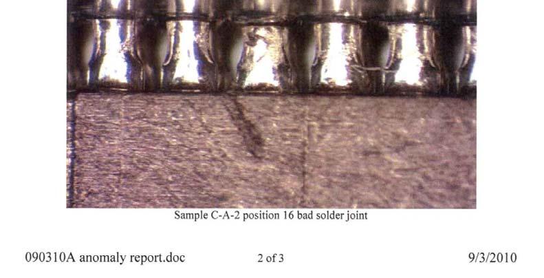
38 APPENDIX A TEST ANOMALY REPORT TR#210329, REV of 41
39 TR#210329, REV of 41


40 TR#210329, REV of 41


41 TR#210329, REV of 41
NOVEMBER 28, 2007 TEST REPORT #207493B TLSD/TMM SERIES CONNECTOR TESTING PART NUMBER TLSD L-N TMM L-D-SM-A SAMTEC, INC.
 NOVEMBER 28, 2007 TEST REPORT #207493B TLSD/TMM SERIES CONNECTOR TESTING PART NUMBER TLSD-25-00-01-L-N TMM-125-01-L-D-SM-A SAMTEC, INC. APPROVED BY: DOMINIC ARPINO PROGRAM MANAGER CONTECH RESEARCH, INC.
SEPTEMBER 28, 2009 TEST REPORT # LSHM SERIES CONNECTOR TESTING PART: LSHM L-DV-A-N MATING PART: LSHM L-DV-A-N SAMTEC, INC.
 SEPTEMBER 28, 2009 TEST REPORT #209422 LSHM SERIES CONNECTOR TESTING PART: LSHM-150-06.0-L-DV-A-N MATING PART: LSHM-150-06.0-L-DV-A-N SAMTEC, INC. APPROVED BY: ALICE HATHAWAY PROJECT ENGINEER CONTECH RESEARCH,
Product Specification
 Product Specification PR041-01 Revision A0 (Date 4-3-2017) Stewart Connector 11118 Susquehanna Trail South Glen Rock, Pa. 17327-9199 Ph: (717) 235-7512 Fax: (717) 235-4675 Product Specification PR0410-01
SAMTEC POWER CHARACTERIZATION
 Project Number: Tracking Code: TC0838--1970_ReportRev1 Requested by: Bryon Saylor Date: 1/19/2009 Product Rev: BH Part #: SSW-150-01-G-D/TSW-150-07-L-D Lot #: 6/24/2008 Tech: Tony Wagoner Eng: Dave Scopelliti
SAMTEC POWER CHARACTERIZATION
 Project Number: Tracking Code: Requested by: Bryon Saylor Date: 1/9/2009 Product Rev: P Part #: SQW-150-01-L-D/TMMH-150-01-L-DV Lot #: 8/25/2008 Tech: Tony Wagoner Eng: Dave Scopelliti Part description:
PRODUCT SPECIFCATION GS MINI-SAS HD External Cable to Board Connector System. 1 of 14 F. Roger Cheng TYPE NUMBER
 1 of 14 F TABLE OF CONTENTS 1.0 OBJECTIVE... 3 2.0 SCOPE... 3 3.0 APPLICABLE DOCUMENTS... 3 3.1 FCI SPECIFICATIONS... 3 3.2 OTHER STANDARDS AND SPECIFICATIONS... 3 3.3 FCI PRODUCT QUALIFICATION TEST REPORTS...
Mar11 Rev C
 Product Specification 108-1956 11Mar11 Rev C PC/104 and PC/104-Plus Connector Systems 1. SCOPE 1.1. Content This specification covers performance, tests and quality requirements for the TE Connectivity
PDS: Rev :A STATUS:Released Printed: Jan 04, 2012
 of 2 A.0 Objective This specification defines the performance, test, quality and reliability requirements of the USB3.0 Standard- A Receptacle. 2.0 Scope This specification is applicable to the termination
Mini PCI Express & msata Connector
 09.Mar.2012 Rev. C Mini PCI Express & msata Connector 1 Scope: 1.1 Contents This specification covers the requirements for product performance, test methods and quality assurance provisions of MINI PCI
PRODUCT SPECIFICATION
 1.0 SCOPE DDR4 DIMM SOCKET This Product Specification covers the 0.85mm centerline gold plated DDR4 DIMM edge card connector for 1.40 ± 0.10 thick memory modules..0 PRODUCT DESCRIPTION.1 PRODUCT NAME AND
PRODUCT SPECIFICATION
 RECEPTACLE 1.0 SCOPE This Product Specification covers the performance requirements of the Serial Attach SCSI / High Speed Serialized host receptacle connector. 2.0 PRODUCT DESCRIPTION 2.1 PRODUCT NAME
Feb-2016 Rev 1
 08-509-2 22-Feb-206 Rev USB Type-C Connector Scope :. Contents This specification covers the requirements for product performance, test methods and quality assurance provisions of TE Connectivity USB type
Grayhill, Inc. La Grange, IL
 Device Under Test: 62SY15045 Physical Test: Dimensional, Mechanical Vibration, Mechanical Shock Electrical Test: Contact Resistance, Thermal Shock Test Report Number: SP02-1875 Test Start Date: January
ENVIRONMENTAL TEST REPORT N REV. N/C TEST STANDARDS: MIL-STD-202G
 ENVIRONMENTAL TEST REPORT 1510-107N REV. N/C TEST STANDARDS: MIL-STD-202G For ANALOG DEVICES INC 3 TECHNOLOGY WAY NORWOOD, MA 02053 On ELECTRONICS MODULE MODEL NUMBER: NONE ; PART NUMBER: NONE ; SERIAL
zqsfp+stacked Connector and Cage Assembly
 Product Specification 108-60102 May 27, 2015 Rev A1 zqsfp+stacked Connector and Cage Assembly 1. SCOPE 1.1. Content This specification defines performance, test and quality requirements for the zqsfp+stacked
PRODUCT SPECIFICATION
 Dual SIM Card Connector, Retainer Type, 8-Pin, SMT, 3.0mm Profile Page 1 Dual SIM Card Connector, Retainer Type, 8-Pin, SMT, 3.0mm Profile Page 2 1.0 SCOPE. This specification covers performance, tests
PRODUCT SPECIFICATION
 RECEPTACLE.0 SCOPE This Product Specification covers the performance requirements of the Serial Attach SCSI / High Speed Serialized host receptacle connector. 2.0 PRODUCT DESCRIPTION 2. PRODUCT NAME AND
Product Specification AMP Connector USB Consortium, Plug & Receptacle. Lead Free Version
 Product Specification 108-60034 AMP Connector USB Consortium, Plug & Receptacle Lead Free Version 1. Scope: 1.1 Contents: This specification covers the requirements for product performance, test methods
PRODUCT SPECIFICATION
 SIM Card Connector, Hinged Type, 8 Pin, SMT, 1.50mm Profile. Page 1 SIM Card Connector, Hinged Type, 8 Pin, SMT, 1.50mm Profile. Page 2 1.0 SCOPE. This specification covers performance, tests and quality
Nano Pitch I/O Pluggable Connector
 Design Objective 108-60118 06 Aug 2017 Rev 1 Nano Pitch I/O Pluggable Connector 1. SCOPE 1.1. Content This specification covers performance, tests and quality requirements for the TE Connectivity (TE)
Product Specification. CLOUDSPLITTER Connector System
 Product Specification 01NOV2013 Rev A CLOUDSPLITTER Connector System 1. SCOPE 1.1. Content This specification covers the performance, tests and quality requirements for the CLOUDSPLITTER connector system.
Jun11 Rev A
 Product Specification MULTIGIG* Extreme 108-2072-2 28Jun11 Rev A 1. SCOPE 1.1. Content This document is specific to features, performance and testing of a metal shell and hardware kit which can be installed
Mini PCI Express Card Socket
 Mini PCI Express Card Socket Document No: Page: 1 of 4 1. Scope This specification covers the material and performance requirements for the Mini PCI Express Card Socket series. 2. Applicable documents
Jun-2012 Rev B2
 Product Specification 108-99116 11-Jun-2012 Rev B2 USB / External Serial ATA Connector, 2 in 1 Type 1. SCOPE 1.1. Contents This specification covers the performance, tests and quality requirements for
Vertical type HDMI Receptacle Connector
 Product Specification 108-60086 Vertical type HDMI Receptacle Connector 1 Scope: 11 Contents This specification covers the requirements for product performance, test methods and quality assurance provisions
PRODUCT SPECIFICATION
 SIM Card Connector, Hinged Type, 6 Pin, SMT, 1.85mm Profile. Page 1 SIM Card Connector, Hinged Type, 6 Pin, SMT, 1.85mm Profile. Page 2 1.0 SCOPE. This specification covers performance, tests and quality
Aug04 Rev D EC
 Product Specification 108-1163 18Aug04 Rev D EC 0990-1127-04 Modular Plugs, Thru-Hole and Surface Mount Jacks, Data and Telephone, PCB Mounted 1. SCOPE 1.1. Content This specification covers the performance,
USB 3.0 Plug & Receptacle
 USB 3.0 Plug & Receptacle 1. Scope: 1.1 Contents: This specification covers the requirements for product performance, test methods and quality requirements of Tyco lectronics Universal Serial Bus (USB)
PRODUCT SPECIFICATION
 PRODUCT SPECIFITION PAGE: 1 OF 7 REV: A Serial ATA Connector, (22SAPP-X-X) LIST OF REVISION REV PAGE DESCRIPTION ECN. NO. DATE A 01-07 NEW E9201035 01/24/03 PRODUCT SPECIFITION PAGE: 2 OF 7 REV: A Serial
PRODUCT SPECIFICATION CUSTOM CONFIGURABLE MODULAR POWER DOCK CONNECTOR SYSTEM
 1.0 SCOPE This Product Specification covers the custom configurable modular printed circuit board (PCB) Dock Connector System with gold plating. 2.0 PRODUCT DESCRIPTION 2.1 PRODUCT NAME AND SERIES NUMBER(S)
PRODUCT SPECIFICATION
 DC Power Jack, Thru-Hole, Horizontal, w/locating Pegs, Ø2.00mm Page 1 DC Power Jack, Thru-Hole, Horizontal, w/locating Pegs, Ø2.00mm Page 2 1.0 SCOPE. DC Power Jack, Thru-Hole, Horizontal, w/locating Pegs,
Product Specification
 USB A CONNECTOR 1 of 7 J 1.0 GENERAL This specification defines the performance, tests and quality requirements for the USB A connector. This document is composed of the following sections. 1. General
3M SlimLine 85ohm Cable Assembly
 Product Specifications May 2017 78-5102-0240-7, Rev B Scope This document summarizes test methods, test conditions, and product performance requirements for 3M SlimLine 85ohm Cable Assembly. Reference
Product Specification. Mezza-pede SMT Connector Low Profile 1.0mm Pitch
 Mezza-pede SMT Connector Low Profile 1.0mm Pitch Rev. 1 December 7, 2016 1.0 Scope This product specification applies to 1.0mm pitch Mezza-pede SMT Connectors, designed for the mating and unmating of a
TABLE OF CONTENTS 3.0 QUALITY ASSURANCE PROGRAM TEST EQUIPMENT AND INSTRUMENTATION 5 ATTACHMENTS A PHOTOGRAPHS A-1 B VIBRATION TEST DATA B-1
 Page No. 2 TABLE OF CONTENTS Page No. 1.0 INTRODUCTION 3 1.1 Scope 3 1.2 References 3 1.3 Test Specimen Description 3 1.4 Summary 3 2.0 TEST PROCEDURES AND RESULTS 4 2.1 Vibration Resonance Search Test
3M (TM) Ribbon Cable Socket and Header, 451 and 452 Series.050" x.050" (1.27 mm x 1.27 mm)
 Ribbon Cable Socket and Header, 451 and 452 Series.050 x.050 (1.27 mm x 1.27 mm)") 3M (TM) Ribbon Cable Socket and Header, 451 and 45 Series.050" x.050" (1.7 mm x 1.7 mm) Product Specification: 78-510-0091-4 Revised: 1-6-016 78-510-0091-4 Rev D of 9 Page Cover Page..... 1 Contents 1.
3M (TM) Ribbon Cable Socket and Header, 451 and 45 Series.050" x.050" (1.7 mm x 1.7 mm) Product Specification: 78-510-0091-4 Revised: 1-6-016 78-510-0091-4 Rev D of 9 Page Cover Page..... 1 Contents 1.
PRODUCT SPECIFICATION. This specification defines the detailed requirements for the Minitek Pwr3.0 wire to wire and wire to board connectors.
 s-12-1177*1.0 SCOPE 1 of 8 D This specification defines the detailed requirements for the Minitek Pwr3.0 wire to wire and wire to board connectors. 2.0 APPLICABLE DOCUMENTS The following documents, of
PRODUCT SPECIFICATION
 1.25 mm pitch SMT Wire to Board Connector 1 of 7 A 1.0 SCOPE This specification covers performance, tests and quality requirements for 1.25 mm pitch Wire to Board DIP & SMT Type of 10114826~10114831 Series.
3M 100G QSFP28 Direct Attach Copper Cable Assemblies, 9Q Series
 Product Specifications June 2017 78-5102-0262-1, Rev A 3M 100G QSFP28 Direct Attach Copper Cable Assemblies, 9Q Series Scope This document summarizes test methods, test conditions, and product performance
PRODUCT SPECIFICATION. MES3050 Rev A Date 11/06/09 T-Flash Memory Card, Push-Push + SIM Card (6-Pin), Push-Pull (2-in-1 Combo Connector).
, Push-Pull (2-in-1 Combo Connector).") Page 1 Page 2 1.0 SCOPE. This specification covers performance, tests and quality requirements for the 2-in-1 Combo Connector MES3050 (T-Flash Push-Push + SIM 6-Pin Push-Pull). 2.0 PRODUCT NAME AND PART
Page 1 Page 2 1.0 SCOPE. This specification covers performance, tests and quality requirements for the 2-in-1 Combo Connector MES3050 (T-Flash Push-Push + SIM 6-Pin Push-Pull). 2.0 PRODUCT NAME AND PART
3M Ribbon Cable Socket and Header, Series 451 & " x.050" (1.27 mm x 1.27 mm)
") 1 of 8 3M Ribbon Cable Socket and Header, Series 451 & 452.050" x.050" (1.27 mm x 1.27 mm) Product Specification: 78-5102-0091-4 Revised: 05-01-2013 2 of 8 Page Cover Page..... 1 Contents 2 1. Scope......
1 of 8 3M Ribbon Cable Socket and Header, Series 451 & 452.050" x.050" (1.27 mm x 1.27 mm) Product Specification: 78-5102-0091-4 Revised: 05-01-2013 2 of 8 Page Cover Page..... 1 Contents 2 1. Scope......
Cobham Advanced Electronic Solutions Inc Environmental Test Services
 Cobham Advanced Electronic Solutions Inc Environmental Test Services Core Systems Core Systems MLD160 Rugged HP Server has passed all Operational Shock per MIL-STD-810G, Method 516.6, procedure I, 40gs,
 Distributed by: www.jameco.com 1-800-831-4242 The content and copyrights of the attached material are the property of its owner. Power Connectors FEATURES AND SPECIFICATIONS Features and Benefits Positive
AMP-TWIST* 6S Series SL Jack
 Product Specification 108-93003 16/Mar/2011 Rev E AMP-TWIST* 6S Series SL Jack 1. SCOPE 1.1 Content This specification covers performance, tests and quality requirements for AMP NETCONNECT*, AMP- TWIST*
SPECIFICATION MARCH MULTI MEDIA MEMORY CARD CONNECTOR. Kingfont Precision Ind. Co., Ltd. 17 FL-3, NO. 738, CHUNG CHENG ROAD.
 SPECIFICATION SPEC. NO. SP0A24 REV B DATE MARCH-26-2004 PRODUCT NAME PRODUCT NO MULTI MEDIA MEMORY CARD CONNECTOR SDCMF-X07XXW1XX Kingfont Precision Ind. Co., Ltd. 738 17 3 17 FL-3, NO. 738, CHUNG CHENG
Smiths Connectors Sabritec Test Report High Speed and Durability Test Quadrax Pin Contact & SKT Contacts
 Smiths Connectors Sabritec Test Report High Speed and Durability Test Quadrax Pin Contact 019135-8019 & SKT Contacts 019235-8019 Rev. A 11-16-2011 www.smithsconnectors.com Revision Letter Page Number Paragraph
NeXLev Product Specification TB2144
 NeXLev Product Specification TB2144 Revision B Specification Revision Status Revision SCR No. Description Initial Date - S0161 New Release DM 4/5/2006 A S1357 Update copper material callout, DM 8/31/09
OCT 17 Rev A
 Product Specification 108-133085 05OCT 17 Rev A The product described in this document has not been fully tested to ensure conformance to the requirements outlined below. Therefore, TE Connectivity (TE)
PwrMAX High Power Connector System (Preliminary)
") 1 of 14 5 1.0 OBJECTIVE 2.0 SCOPE This specification defines the performance, test, quality and reliability requirements of the PwrMAX Power Connector System. 3.0 GENERAL This specification is applicable
1 of 14 5 1.0 OBJECTIVE 2.0 SCOPE This specification defines the performance, test, quality and reliability requirements of the PwrMAX Power Connector System. 3.0 GENERAL This specification is applicable
Test Report GT For SuperSeal HDMI Design Preliminary Qualification Tests ZR07-17NH ZRG6-17NH-06
 TEST REPORT No. GT-18-149 July 22, 2018 Glenair, Inc. 1211 Air Way, Glendale, California, 91201 Tel: (818) 247-6000 Fax: (818) 247-7240 July 22, 2018 Test Report GT-18-149 For SuperSeal HDMI Design Preliminary
PERFORMANCE SPECIFICATION SHEET
 INCH-POUND MIL-PRF-39016/41E 15 June 2005 SUPERSEDING MIL-PRF-39016/41D 20 July 1988 PERFORMANCE SPECIFICATION SHEET RELAYS, ELECTROMAGNETIC, ESTABLISHED RELIABILITY, DPDT, LOW LEVEL TO 1 AMPERE, TERMINALS
Amphenol Amphenol Taiwan Corporation Sheet 1 of 9
 Amphenol Amphenol Taiwan Corporation Sheet 1 of 9 Title: Part Number: Description: MINI SAS Connectors Product Specification G40 Series 0.80mm Pitch, Cable End and Board Mount Revisions Control Rev. ECN
/June/2014 Rev C
 Qualification Test Report 501-93032 18/June/2014 Rev C AMP-TWIST Series Jacks for Class EA systems 1. INTRODUCTION 1.1 Purpose Qualification testing on AMP-TWIST* Series Jacks for Class EA Systems, to
PERFORMANCE SPECIFICATION SHEET
 PERFORMANCE SPECIFICATION SHEET INCH-POUND 1 April 2005 SUPERSEDING MIL-PRF-39016/18G 20 July 1988 RELAYS, ELECTROMAGNETIC, ESTABLISHED RELIABILITY, DPDT, LOW LEVEL TO 1.0 AMPERE WITH INTERNAL DIODE FOR
PRODUCT SPECIFICATION TITLE PAGE REVISION
 1 of 14 A 1.0 OBJECTIVE This specification defines the performance, test quality and reliability requirement of the Micro Serial-ATA Host and Device connectors. 2.0 SCOPE This specification is applicable
Product Specification
 MEC8 Series Socket, Vertical Orientation Other configurations available for: Right Angle Application Edge Mount Application Press Fit Application See www.samtec.com for more information. 1.0 SCOPE 1.1
[0.057] 5.8 [0.23]
![[0.057] 5.8 [0.23]](/thumbs/86/93524652.jpg "[0.057] 5.8 [0.23]") Product Specification 7 March 13 Rev A1 SL Series Jacks, Category 6 1. SCOPE 1.1 Content This specification covers performance, tests and quality requirements for AMP NETCONNECT*, Category 6 SL Jacks used
Product Specification 7 March 13 Rev A1 SL Series Jacks, Category 6 1. SCOPE 1.1 Content This specification covers performance, tests and quality requirements for AMP NETCONNECT*, Category 6 SL Jacks used
Product Performance Specifications QuadraPaddle Connector
 Product Performance Specifications QuadraPaddle Connector 1. Scope 1.1 Content This specification covers the performance, tests and quality requirements for the QuadraPaddle Connector and connector system.
 Distributed by: www.jameco.com 1-800-831-4242 The content and copyrights of the attached material are the property of its owner. C 2.54mm (.100") Pitch FEATURES AND SPECIFICATIONS Features and Benefits
PRE-ASSEMBLY COMPONENT MATCHING PROCEDURE FOR THE HVA PWA OPTOCOUPLERS. GP-B Procedure P0716 Rev A August 21, 2000
 W. W. Hansen Experimental Physics Laboratory STANFORD UNIVERSITY STANFORD, CALIFORNIA 94305-4085 Gravity Probe B Relativity Mission PRE-ASSEMBLY COMPONENT MATCHING PROCEDURE FOR THE HVA PWA OPTOCOUPLERS
PERFORMANCE SPECIFICATION SHEET
 INCH-POUND MIL-PRF-39016/23F 15 June 2005 SUPERSEDING MIL-PRF-39016/23E 20 July 1988 PERFORMANCE SPECIFICATION SHEET RELAYS, ELECTROMAGNETIC, ESTABLISHED RELIABILITY, SPDT, LOW LEVEL TO 1.0 AMPERE WITH
PERFORMANCE SPECIFICATION SHEET
 PERFORMANCE SPECIFICATION SHEET INCH-POUND w/amendment 1 22 September 2005 SUPERSEDING MIL-PRF-39016/19G 1 April 2005 RELAYS, ELECTROMAGNETIC, ESTABLISHED RELIABILITY, DPDT, LOW LEVEL TO 1 AMPERE WITH
PRODUCT SPECIFICATION
 SINGLE ROW CONNECTOR SYSTEM 1.0 SCOPE This Product Specification covers the 3.00 mm (.118 inch) centerline (pitch) square pin headers when mated with either printed circuit board (PCB) connector or connectors
PRODUCT SPECIFICATION
 1.0 SCOPE This Product Specification covers the 3.00 mm (.118 inch) centerline (pitch) square pin headers when mated with either printed circuit board (PCB) connector or connectors terminated with 20 to
ENVIRONMENTAL REPORT: EXECUTIVE SUMMARY 6/24/09 Testing performed 6/21/09 thru 6/24/09
 a subsidiary of SL INDUSTRIES, INC. ISO 9001:2000 CERTIFIED 6050 King Dr., Bldg. A Ventura, CA 93003 TELEPHONE (805) 486-4565 FAX (858) 712-2040 www.slpower.com ENVIRONMENTAL REPORT: EXECUTIVE SUMMARY
/June/2013 Rev B
 Qualification Test Report 501-93016 14/June/2013 Rev B AMP-TWIST* 6S Series SL Jack 1. INTRODUCTION 1.1 Purpose Testing were performed on AMP-TWIST* 6S Series SL Jack, to determine its conformance to the
Vibration and Shock Testing. for the. Optima EPS Corporation Rack (70 x 19 W x 36 L, 500 lbs lbs)
") MET Laboratories, Inc. Safety Certification - EMI - Telecom Environmental Simulation 914 WEST PATAPSCO AVENUE! BALTIMORE, MARYLAND 21230-3432! PHONE (410) 354-3300! FAX (410) 354-3313 Vibration and Shock
MET Laboratories, Inc. Safety Certification - EMI - Telecom Environmental Simulation 914 WEST PATAPSCO AVENUE! BALTIMORE, MARYLAND 21230-3432! PHONE (410) 354-3300! FAX (410) 354-3313 Vibration and Shock
Product Specification
 SLH Series Socket, Vertical Orientation TLH Series Terminal, Vertical Orientation See www.samtec.com for more information. Page 1 1.0 SCOPE 1.1 This specification covers performance, testing and quality
Product Specification
 HSEC8-DV Series.062 (1,57 mm) Card Thickness Other configurations available for: Edge Mount, Right Angle, -Through, Board Lock, Guide Rails, Weld Tab, Latching, Pick & Place Pad, and ECDP Latching options
[0.057] 5.8 [0.23]
![[0.057] 5.8 [0.23]](/thumbs/92/109560281.jpg "[0.057] 5.8 [0.23]") Product Specification 7 June 13 Rev B SL Series Jacks, Category 6 1. SCOPE 1.1 Content This specification covers performance, tests and quality requirements for AMP NETCONNECT*, Category 6 SL Jacks used
Product Specification 7 June 13 Rev B SL Series Jacks, Category 6 1. SCOPE 1.1 Content This specification covers performance, tests and quality requirements for AMP NETCONNECT*, Category 6 SL Jacks used
Product Specification
 MEC6 Series Socket, Vertical Orientation Other configurations available for: Right Angle Application See www.samtec.com for more information. Page 1 1.0 SCOPE 1.1 This specification covers performance,
Product Specification
 MCX Jack, Straight Orientation, Through-hole MCX Plug, Straight Orientation, Through-hole Other configurations available for: Vertical and right angle cable-to-board applications Through-hole, surface
PRODUCT SPECIFICATION
 1 of 15 G 1.0 OBJECTIVE This specification defines the performance, test, quality, and reliability requirements of the GIG-ARRAY High Speed Mezzanine 1.00 x 0.65 mm BGA Differential Connector System. This
QUALIFICATION TEST REPORT
 QUALIFICATION TEST REPORT FOR CARLISLE IT P/N: P317GD8-1CC (CGB4PS08VL00) and P186GD8-1CC (CGC4RS08236) DATE CODE: 1541, 1542 WO: 1260651, 1261323 SSMP MALE, 8 POSITION, PCB VERTICAL MOUNT CARLISLE INTERCONNECT
REPORT OF ELECTROMAGNETIC SUSCEPTIBILITY TESTS PERFORMED ON GPS ANTENNA PART NUMBER 42G1215A-XT-1-N PREPARED FOR:
 Page 1 of 40 National 1536 East Valencia Drive Technical Fullerton, California 92831 Systems Tel: 714-879-6110 Fax: 714-879-6117 www.ntscorp.com REPORT OF ELECTROMAGNETIC SUSCEPTIBILITY TESTS PERFORMED
SSL 1.1 Series. Product Data Sheet REV. 4, 2014 JUN
 SSL 1.1 Series Product Data Sheet REV. 4, 2014 JUN General Specification Number of Positions Current Rating 2, 4, 6P 3A (Max) Voltage Rating Dielectric Withstand Voltage Durability Color Operating Temperature
BOARD-LEVEL TEST PROCEDURE FOR THE GYROSCOPE SUSPENSION SYSTEM (GSS) MUX/OSCILLATOR/CHARGE CTRL (MUX) BOARD. GP-B Procedure P0607 Rev -
 MUX/OSCILLATOR/CHARGE CTRL (MUX) BOARD. GP-B Procedure P0607 Rev -") W. W. Hansen Experimental Physics Laboratory STANFORD UNIVERSITY STANFORD, CALIFORNIA 94305-4085 Gravity Probe B Relativity Mission BOARD-LEVEL TEST PROCEDURE FOR THE GYROSCOPE SUSPENSION SYSTEM (GSS)
W. W. Hansen Experimental Physics Laboratory STANFORD UNIVERSITY STANFORD, CALIFORNIA 94305-4085 Gravity Probe B Relativity Mission BOARD-LEVEL TEST PROCEDURE FOR THE GYROSCOPE SUSPENSION SYSTEM (GSS)
OCuLink x4 Cable end
 PAGE /5 OCuLink x4 Receptacle Connector OCuLink x4 Cable end PAGE 2/5.0 SCOPE This Product Specification covers the performance requirements of the Pitch 0.5mm PCI-e OCuLink Pluggable Connectors 2.0 PRODUCT
AMPMODU* MOD I Interconnection System
 Product Specification AMPMODU* MOD I Interconnection System 03 JUN 2013 Rev E All Paragraphs Revised 1. SCOPE This specification covers performance and test requirements for the AMPMODU MOD I Interconnection
The Specialty Lab, Inc. Lab Report Page 1 of 13 NITEK. NEMA TS-2 Testing Per Version and Nitek instructions. May 21, 2013.
 The Specialty Lab, Inc. Lab Report 13-3090 Page 1 of 13 NEMA TS-2 Testing Per Version 02.06 and Nitek instructions May 21, 2013 Prepared for: 5410 Newport Drive #24 Rolling Meadows, IL 60008 Report Number
REPORT OF ELECTROMAGNETIC SUSCEPTIBILITY TESTS PERFORMED ON GPS ANTENNA PART NUMBER 42G1215A-XT-1-N PREPARED FOR:
 Page 1 of 64 National 1536 East Valencia Drive Technical Fullerton, California 92831 Systems Tel: 714-879-6110 Fax: 714-879-6117 www.ntscorp.com REPORT OF ELECTROMAGNETIC SUSCEPTIBILITY TESTS PERFORMED
FUNCTIONAL TEST PROCEDURE FOR THE GYROSCOPE SUSPENSION SYSTEM (GSS) AFT CONTROL UNIT (ACU) SUBSYSTEM. GP-B Procedure P0715 Rev September 22, 2000
 AFT CONTROL UNIT (ACU) SUBSYSTEM. GP-B Procedure P0715 Rev September 22, 2000") P0715 Rev. September 22, 2000 W. W. Hansen Experimental Physics Laboratory STANFORD UNIVERSITY STANFORD, CALIFORNIA 94305-4085 Gravity Probe B Relativity Mission FUNCTIONAL TEST PROCEDURE FOR THE GYROSCOPE
P0715 Rev. September 22, 2000 W. W. Hansen Experimental Physics Laboratory STANFORD UNIVERSITY STANFORD, CALIFORNIA 94305-4085 Gravity Probe B Relativity Mission FUNCTIONAL TEST PROCEDURE FOR THE GYROSCOPE
Amphenol Amphenol Taiwan Corporation Sheet 1 of 11
 Amphenol Amphenol Taiwan Corporation Sheet 1 of 11 Title: Part Number: Description: RJ-MAG Connector Product Specification RJMG21202XXXXXX RJmag 1 x 2-Port W/ LED Revisions Control Rev. ECN Number Originator
OSFP Connector Cage & Cable System
 PAGE /6 /5/7 UNRESTRICTED OSFP Connector Cage & Cable System PAGE /6 /5/7 UNRESTRICTED.0 SCOPE This Product Specification covers performance, test and quality requirements for the JPC Quad Small Form Factor
Amphenol Amphenol Taiwan Corporation Sheet 1 of 16
 Amphenol Amphenol Taiwan Corporation Sheet 1 of 16 Title: USB3.0 Product Specification Part Number: GSB3 Series Description: USB3.0 A&B Type Plug & Receptacle Revisions Control Rev. ECN Number Originator
PRODUCT SPECIFICATION
 1.0 SCOPE This Product Specification covers the 3.00 mm (.118 inch) centerline (pitch) square pin headers when mated with either printed circuit board (PCB) connector or connectors terminated with 20 to
ON-BOARD A/D AND D/A CONVERTER CALIBRATION PROCEDURE FOR GSS FORWARD SUSPENSION UNITS (FSU) GP-B Procedure P0892 Rev -
 GP-B Procedure P0892 Rev -") W. W. Hansen Experimental Physics Laboratory STANFORD UNIVERSITY STANFORD, CALIFORNIA 94305-4085 Gravity Probe B Relativity Mission ON-BOARD A/D AND D/A CONVERTER CALIBRATION PROCEDURE FOR GSS FORWARD
W. W. Hansen Experimental Physics Laboratory STANFORD UNIVERSITY STANFORD, CALIFORNIA 94305-4085 Gravity Probe B Relativity Mission ON-BOARD A/D AND D/A CONVERTER CALIBRATION PROCEDURE FOR GSS FORWARD
PERFORMANCE SPECIFICATION SHEET CONNECTORS, COAXIAL, RADIO FREQUENCY, SERIES C (UNCABLED-RECEPTACLE, FEMALE, JAM NUT MOUNTED, HERMETIC SEAL, CLASS 2)
") INCH-POUND MIL-PRF-39012/14C 10 August 2016 SUPERSEDING MIL-PRF-39012/14B 18 September 1977 PERFORMANCE SPECIFICATION SHEET CONNECTORS, COAXIAL, RADIO FREQUENCY, SERIES C (UNCABLED-RECEPTACLE, FEMALE,
INCH-POUND MIL-PRF-39012/14C 10 August 2016 SUPERSEDING MIL-PRF-39012/14B 18 September 1977 PERFORMANCE SPECIFICATION SHEET CONNECTORS, COAXIAL, RADIO FREQUENCY, SERIES C (UNCABLED-RECEPTACLE, FEMALE,
PERFORMANCE SPECIFICATION
 INCH-POUND MIL-PRF-6106/13F 17 November 2011 SUPERSEDING MIL-PRF-6106/13E 10 November 2000 PERFORMANCE SPECIFICATION RELAY, ELECTROMAGNETIC, 25 AMPERE, 3PST, NO, WITH 2 AMPERE 1PDT AUXILIARY CONTACTS,
 Distributed by: www.jameco.com 1-800-831-4242 The content and copyrights of the attached material are the property of its owner. 0.80mm (.031") Pitch Small Form-Factor Pluggable (SFP) Receptacle 74441
Vibration Transducer Calibration System
 0 1 Overview is designed for calibrating sensitivity, frequency response characteristic and amplitude linearity of acceleration transducer. There are three basic operation modes for the calibration system:
Specification of Analog MEMS Microphone
 Specification of Analog MEMS Microphone RoHS Compliance & Halogen Free Waterproof MEMS Microphone Model: SA04BA383-V21 Eng.No:SA1602011 Designed By: A a r o n 0 7. 0 2 Checked By: E s t e r 0 7. 0 2 Approved
BOARD-LEVEL TEST PROCEDURE FOR THE GYROSCOPE SUSPENSION SYSTEM (GSS) FORWARD BACKPLANE (FBP) BOARD. GP-B Procedure P0601 Rev
 FORWARD BACKPLANE (FBP) BOARD. GP-B Procedure P0601 Rev") P0601 Rev. May 10, 2000 W. W. Hansen Experimental Physics Laboratory STANFORD UNIVERSITY STANFORD, CALIFORNIA 94305-4085 Gravity Probe B Relativity Mission BOARD-LEVEL TEST PROCEDURE FOR THE GYROSCOPE
P0601 Rev. May 10, 2000 W. W. Hansen Experimental Physics Laboratory STANFORD UNIVERSITY STANFORD, CALIFORNIA 94305-4085 Gravity Probe B Relativity Mission BOARD-LEVEL TEST PROCEDURE FOR THE GYROSCOPE
PERFORMANCE SPECIFICATION SHEET SWITCHES, SENSITIVE, SPDT, LEAF ACTUATOR, LOW LEVEL TO 4 AMPERES, HERMETIC SEAL
 INCH-POUND MIL-PRF-8805/8H 6 December 0 SUPERSEDING MIL-PRF-8805/8G 0 April 006 PERFORMANCE SPECIFICATION SHEET SWITCHES, SENSITIVE, SPDT, LEAF ACTUATOR, LOW LEVEL TO 4 AMPERES, HERMETIC SEAL This specification
PRODUCT SPECIFICATION
 PRODUCT SPECIFICATIO LAGUAGE JAPAESE EGLISH SCOPE 1 25 9(& 2$ This specification covers the 1.25mm PITCH FFC/FPC COECTOR series. PRODUCT AME AD PART UMBER Product ame 4XÇ( X;O Housing Assembly 4XÇ( X;O
Description. Features. Continuous RA8 Series RA16 Series RA22 Series Units. ) 4 to to to 275 V DC Voltage Range (V M(DC)
 4 to to to 275 V DC Voltage Range (V M(DC)") RA Varistor Series RoHS Description The RA Series transient surge suppressors are varistors (MOVs) supplied in a low-profile box that features a precise seating plane to increase mechanical stability for
RA Varistor Series RoHS Description The RA Series transient surge suppressors are varistors (MOVs) supplied in a low-profile box that features a precise seating plane to increase mechanical stability for
STANDARD FOR ELECTRICAL CONTACTS, RETENTION CRITERIA
 INCH-POUND MSFC-STD-781 National Aeronautics and REVISION A Space Administration EFFECTIVE DATE: August 1, 2007 George C. Marshall Space Flight Center Marshall Space Flight Center, Alabama 35812 MULTIPROGRAM/PROJECT
Features wideband, 10 to 4200 MHz low insertion loss, 0.6 db typ. feed through terminal per DC port
 Coaxial Bias-Tee 50Ω Wideband 10 to 4200 MHz Maximum Ratings Operating Temperature -55 C to 100 C Storage Temperature -55 C to 100 C RF Power Voltage at DC port Input Current DC resistance from DC to RF&DC
Mar11 Rev A
 Product Specification 108-2055-1 09Mar11 Rev A Two, Three and Four Pair Z-PACK* HM-Zd Plus Connectors 1. SCOPE 1.1. Content This specification covers performance, tests and quality requirements for the
AMP-TWIST* Modular Jack, UTP, Category 6A
 Product Specification 5 July 13 Rev A AMP-TWIST* Modular Jack, UTP, Category 6A 1. SCOPE 1.1 Content This specification covers performance, tests and quality requirements for TE Connectivity*, 6A UTP AMP-