utinkerer v1.1 User s Manual
|
|
|
- Shanna Brooks
- 5 years ago
- Views:
Transcription

1 utinkerer v1.1 User s Manual Last Updated January 6, 2013
2 2
3 WARNING READ BEFORE USE!!! 1) DO NOT OVERLOAD OR SHORT POWER RAILS. out of the Box is not responsible for any damage to personal property through the use of the utinkerer development platform. Use at your own risk. ALWAYS check for power and ground connectivity on all power rails before powering the utinkerer development platform. Short circuits on any of the power rails can result in irreversible damage to the utinkerer as well as any device connected to it, this includes a personal computer(s) connected over USB. In addition to checking for short circuits the user should also consult the electrical specifications portion of this manual before interfacing any device with the utinkerer development platform. 2) DO NOT BEND THE BOARD. The utinkerer development platform should never be bent or exposed to ANY bending force. The utinkerer consists of a 6 layer PCB. Bending can cause undue strain on the copper traces of the PCB. This strain can result in unpredictable behavior and or failure of the device. 3
4 Table of Contents WARNING READ BEFORE USE!!!... 3 The Purpose of This Manual... 5 Use of This Document... 5 Not Finding the Information You Need... 5 Standard Features... 5 External Bus Interface... 6 EBI Connections... 6 Programmable Logic... 7 Analog... 8 USB Virtual Serial Port... 9 Powering the utinkerer...11 Power Source Selection Programming the utinkerer...12 Debugging Appendix...13 Electrical Specifications Glossary Device List and Relevant Documentation Calculations Sensitivity Analysis of ADC Voltage Inputs Due to 5% Resistance Tolerance V Regulator Maximum Current Calculation
5 The Purpose of This Manual This manual is intended as a guide, and serves to overview of the utinkerer development platform. It is not intended as an exhaustive reference. The schematic design files and the bill of materials are provided to the user for this reason. Use of This Document The utinkerer development platform was designed with emphasis towards educational use. In kind this document was crafted towards readers who may be unfamiliar with microprocessors, microcontrollers etc. Many technical and obscure terms encountered in this document are defined in the Glossary. Often as well links are provided to sources of greater detail. Not Finding the Information You Need If in despite our efforts to inform, a portion of the documentation is perceived as lacking please send your feedback here. Likewise any questions may be submitted to the forum here. Standard Features Standard features in this context refer to features specific the utinkerer as opposed to features of the Atxmega128A1U microcontroller. For further details on the full capabilities of the Atxmega128A1U refer to Atmel s documentation, as well as the utinkerer schematic 5

, which is a control signal bank.")
6 External Bus Interface The utinkerer development platform supports 3-port EBI. This allows for expanded capabilities of the microcontroller, via memory mapped devices and memory. This feature also serves as a valuable educational tool, since the EBI allows for a more intimate interaction with the microprocessor core. Students using the EBI are forced to learn the internal workings of the processor; And by doing so the students attain a higher understanding and appreciation of microprocessor design as well as their applications. EBI Connections The external bus interface has two main connection hubs. There is the CPU to CPLD Control header (Figure 1), which is a control signal bank. Via the use of shunts signals may be connected/disconnected from the CPLD. These signals are not inherently connected between the ICs in order to prevent bus conflicts between CPLD and the Xmega, which could result in either or both devices. The second connection hub for EBI is displayed in figure 2. This hub contains direct connections to all of the CPU control signals, the data bus, and 16 distinct address lines, eight of which are sourced though an onboard address latch (U8). This particular configuration is known as 3 port mode for details on this configuration consult the family manual. The family manual also contains relevant timing diagrams in its Appendix section A. Figure 1 CPU to CPLD Control Figure 2Address Data and CPU Control lines 6
.")
7 Programmable Logic The utinkerer development board is designed to support an Altera MAX 3000A series CPLD (complex programmable logic device) via the 44 pin PLCC The CPLD has access to all the major control signals provided by the ATxmega128A1U s EBI interface. These signals must be manually connected via shunts to the connections displayed in (Figure 1). Unallocated CPLD pins displayed in (Figure 3), are general purpose. This includes the interface of 5V CMOS logic devices via open drain i/o configurations. For details consult the Appendix of this document. Figure 3 Unallocated CLPD Connections 7

8 Analog The ATxmega128A1U and many other microcontrollers of its generation have moved to lower voltage inputs to their analog to digital converters (ADCs). Speculating, this is likely due to the desire for higher resolutions and conversion speeds. Such specifications are more easily attained at lower voltages. Regardless of reasoning for lower voltage input levels, a disparity exists in that a considerable amount of signals do not lie within the bounds of the ATxmega128A1U s default analog input level(s). The utinkerer, in an effort to reduce external circuitry size and complexity, has built in pre-amplifiers on ADC inputs AD0-7. The pre-amplifiers essentially remap the range of the ADC from V to a more flexible 0 5V. The pre-amplifiers are designed to work with the internal ADC voltage reference (VREF) of VCC/1.6V (2.0625V when VCC=3.3V). It should be noted that even though the pre-amplifier circuit increases functionality, it also is another source for analog conversion error. For details consult the included sensitivity analysis of the analog pre-amplifiers. ADC input pins AD8-11 are raw inputs. They connect directly to the ATxmega128A1U. Figure 4 Analog Input Pins 8

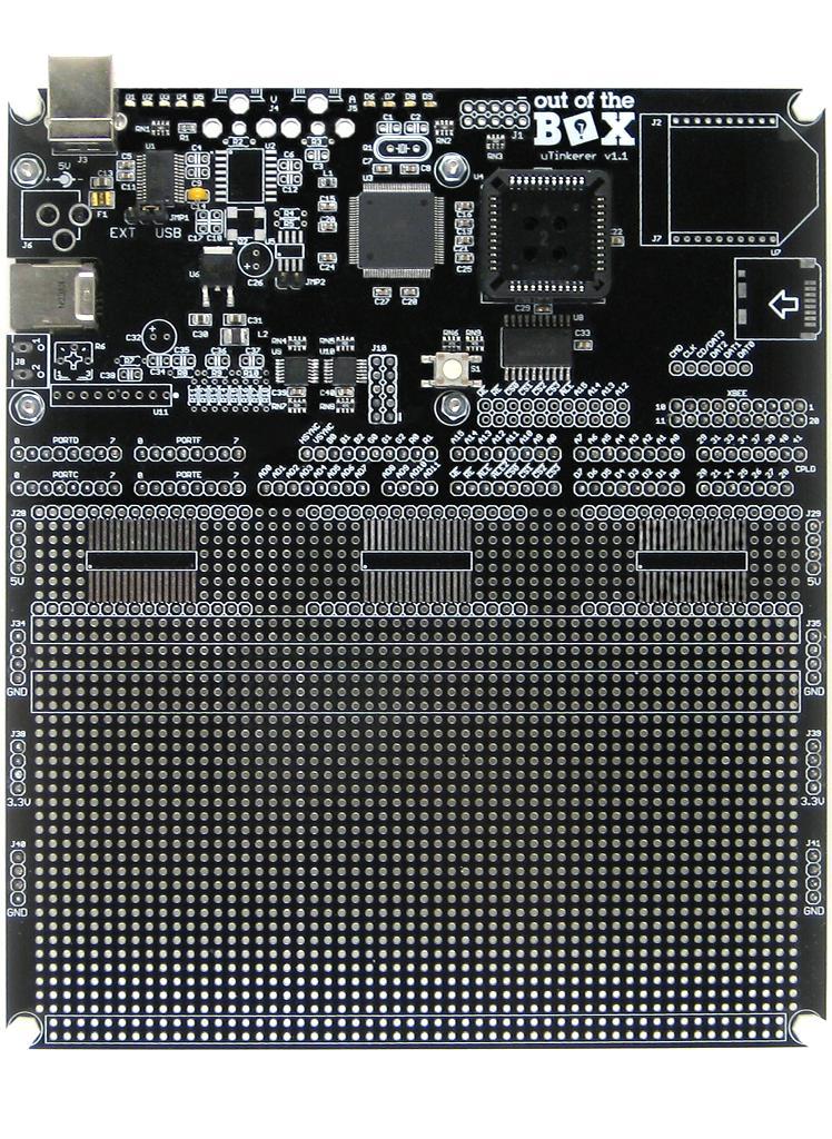
9 USB Virtual Serial Port The utinkerer development platform comes equipped with USB connectivity to your personal computer. This USB connection is recognizable by your computer as a VCP device or Virtual Com Port. This kind of connection is generally used in tandem with a serial terminal, or a custom interface program running on a personal computer. The USB connector displayed in Figure 5 dually serves as the serial port s physical connection to the user s personal computer, as well as the primary means of powering the development platform. Figure 5 USB Serial Connector 9

10 Xmega Dedicated i/o Ports Atmel s Xmega series of microcontrollers have a fairly consistent port peripheral structure for each device family such as the AU (the series found on the utinkerer). The utinkerer development platform directly exposes four ports, C, D, E, and F. These particular junctions house the majority of the Xmega s peripheral hardware connections. For details reference the Device manual under the section of Pinout and Pin Functions pg 59. Figure 6 Xmega i/o Ports 10


11 Powering the utinkerer The utinkerer must be powered by a regulated 5V source such as a computer s USB bus. The reason being, the raw voltage source will directly power select 5V circuits. Further, higher voltage inputs would decrease the 3.3V regulator s current output capacity, due to thermal limitations. The governing equations as well as limitations are detailed here. The utinkerer can accept power from one of two different inputs (both may be connected, just one is selectable at a time). The primary power connection is the USB serial port (Figure 6). By USB 2.0 spec that connection is limited to a maximum of 500mA. The secondary power input option is an optional barrel jack Utilizing connector J6 as the power input will allow for higher currents to be sourced through the 5V and 3.3V power rails. Note some add-on peripherals, due to their inherently high current consumption, can only be powered though J6, these peripherals are directly connected to J6, allowing the primary power input to still be the USB connector (figure 6). Power Source Selection Prior to powering the utinkerer, the power selection jumper, shown in figure 7, must be configured correctly. For USB power selection, a shunt should be placed across the center as well as the pin labeled USB. Similarly if the board is to be powered externally via the optional barrel jack a shunt should be placed over the center pin, as well as the pin labeled EXT. If no shunt is present at all the utinkerer will not power on at all. Also notable, if the does not light, the 3.3V rail is not powered. This happens occasionally despite correct placement of the power source selection shunt, due to a loose fitting shunt contact. Figure 7 Power Source Select 11

12 Programming the utinkerer The utinkerer was designed to be an all inclusive development platform. In following this theme, the utinkerer is intended to house and directly connect to an AVR Dragon hardware programmer. The Dragon serves as the physical interface between, compiled code, and the utinkerer. The Dragon takes compiled code (hex file) and flashes the internal program memory of the ATxmega128A1U. Simply power the utinkerer; connect to the Dragon via, its USB port, and with the help of Atmel Studio program the board. Consult the help documentation within Atmel Studio for details on programming procedures. Figure 8 AVR Dragon USB Port Debugging The AVR Dragon in addition to being a programmer serves as a real time debugging interface. The Dragon uses a JTAG interface to run code line by line, or up to points of interest known as breakpoints. Through debugging the user can view the current status of memory, peripheral registers etc. For further details on the debug interface use and capabilities, consult the help documentation within Atmel Studio. 12
13 Appendix Electrical Specifications Use the following specifications as a quick reference guide. Signals should NEVER fall beneath Minimum ratings or exceed Maximum ratings. Failure to do so may result in irreversible damage to the utinkerer development platform. For more detailed specifications consult the documentation for individual devices. Table 1 Voltage Input Ranges Input type Minimum Typical Maximum External 4.75 V 5.00 V 5.25 V AD V 5.00 V AD V 3.40 V Digital inputs 0.00 V 3.30V 3.60 V CPLD inputs 0.00 V 3.30V 3.60 V 13
14 Table 2 Current Ratings Item Minimum Typical Maximum Nominal Board Consumption* Xmega output current CPLD source current 35mA -25 ma 25 ma -25 ma 25 ma 3.3 V Current 700mA 5.0 V Current 400mA 14
15 Glossary ADC Short for Analog to Digital Converter. An ADC in the most basic sense takes in an analog signal, and outputs a number linearly interpolated from the resolution of the ADC and its respective VREF. Atmel Manufacturer of AVR microcontrollers such as the Xmega line that the utinkerer is based upon. Audio amplifier- an amplifier designed to magnify an audio signal. The magnified signal can be applied to an output device such as a speaker. AVR Dragon The AVR Dragon, also referred to in short as the Dragon, is a programming tool produced by Atmel. It can program and debug most, if not all, AVR microcontrollers. CPLD - Short for Complex Programmable Logic Device. A CPLD is a device composed of basic logic circuit components that can be manipulated to serve a given application. CPLDs are often used at the interface layer between multiple devices. DAC Short for Digital to Analog Converter. A DAC is the complete opposite of and ADC. A number is sent to the DAC, which then generates a voltage in accordance with the input resolution and voltage range of the device. Datasheet Document that describes the functionality of a device. In electronics all circuit board components even resistors have their own respective datasheet(s). Debug Or debugging in the context of this document, refers to the use of an interface tool such as the AVR Dragon to peer into the inner workings of the microcontroller. This is done at a line per line basis in the user s code, or though running to a breakpoint placed by the user. Debugging the processor allows the user to see register settings, memory location values etc. at any given instant. Debugging is nearly identical to simulating, except that a simulator does not run on the application hardware. Simulators depend on a software model of the processor architecture, and have no inherent knowledge of the processor s interaction with additional hardware. All peripheral interactions viewed in a simulator stem from direct manipulation of the programmer. Real time hardware interaction versus user insertion is the defining difference between debugging and simulation. EBI Short for External Bus Interface. This is a specific peripheral name unique to Atmel. The EBI peripheral exposes the processor s data and address buses. Through the exposure of the data and address buses the microcontroller can be interfaced directly to external hardware. IC = Short for integrated circuit. MCU Short for Micro Controller Unit Microcontroller a microprocessor that includes on-chip memory mapped peripherals. 15
16 NTSC Stands for National Television System Committee. In this context NTSC refers to the analog video input signal standard used by television systems in the United States. PCB Stands for Printed Circuit Board. Peripheral in the context of this document peripheral refers to an external or internal memory mapped system or device. Power rails Positive and negative/neutral power signals for any given power voltage level. Pre-Amplifier An amplifier used to condition a signal prior to its desired application. Secure Digital Card Also referred to as an SD Card. A type of non volatile (retains configuration after power is removed) mass storage memory device. Short Circuit - A low resistance connection between two signals, generally power rail signals. Shorts between power rail signals cause the power supply to output large currents. Shorts often result in irreversible damage to electronic devices. Shunt A component used to short two headers together. In operation shunts are generally used at the user interface level, to configure a device. In the case of the utinkerer, several signals are electronically routed to jumpers that utilize shunts to break or create connectivity. Most notable instances of this practice are at the power select JMP1, and CPU to CPLD Control VCP Stands for Virtual Serial Port. A VCP is a specific USB protocol device that functionally mimics a hardware serial port device. Video encoder A video encoder takes in video component signals and encodes them to a signal video signal. In the context of the utinkerer, the video encoder takes in RGB color components, and then outputs a single video signal of the NTSC standard. VREF Short for voltage reference. This is a widely used acronym, but in the context of this document it specifically refers to the voltage referenced of an ADC. The reference is generally the highest level signal an ADC can convert. By setting the ADC VREF you therefore set the acceptable input range of the ADC. XBee A standard of wireless radio interface devices produced by Digi International. Xmega A microcontroller line developed my Atmel. The utinkerer is based on the ATxmega128A1U. 16
17 Device List and Relevant Documentation Table 3 Device List Device Description Documentation U1 USB to serial converter. Takes USART data and translates it via VCP (Virtual Com Port) USB protocol. To use this device with your computer you must first load the drivers that are relevant to your computer and operating system configuration. Datasheet DataSheets/ICs/DS_FT232R.pdf Device Drivers U2 NTSC (Television) video controller IC. This is an optional accessory Datasheet 17
18 U3 Micro-Controller-Unit (MCU) All relevant documents can be found here A1U.aspx?tab=documents *All the MCU peripherals have application notes that further detail use and functionality. Development Procedure Consult the "family manual"(linked below) for peripheral details. Consult the device datasheet for specifics such as electrical characteristics, device errors (errata), and pinouts. Consult application notes for use case examples "Family Manual" Device family "AU" datasheet (this covers peripherals an features in detail) "Device Datasheet" (this covers specifics on the A1U chipset as opposed to the rest of the AU family chips) 18
19 U4 Complex Programmable Logic Device (CPLD). This device can be used to implement discrete logic, ordinarily unavailable without additional circuitry. Max3000A series datasheet df Note pg 21 Details how to use the CPLD to communicate to 5V devices via the MAX 3000A i/o pins via "open drain" configuration. Ordinarily the CPD operates at strictly 3.3V TTL logic U5 Used for generating line voltage level audio signals from the MCU onboard DAC. Assumes a VREF of 1.00V is selected for the DAC. Datasheet U6 3.3V voltage regulator Datasheet pdf U7 Optional micro-sd card reader Datasheet 2.pdf U8 Latch that provides the upper byte of address lines. Datasheet df 19
20 U9 The op-amps are used as voltage followers to eliminate input impedance of signals to the ADC. The output is piped through a voltage divider, that scales the signal (0-5V) to ( V**) which is the range of the ADC when the MCU internal voltage reference of "VCC/1.6" is selected Datasheet edoc/21810f.pdf Exp: 3.3/1.6 = V U11 Optional 3W audio amplifier. The device relies on a 5V power source Datasheet DA7056A.pdf U12,U13 SOIC Adapter footprints n/a **The utinkerer v1.1 was intended to have high precision 1% resistors for the ADC voltage divider. Unfortunately due to assembly error the resistors chosen were 5%. For a full analysis of how this error can affect the ADC conversion accuracy etc see note 1 20
21 Calculations Sensitivity Analysis of ADC Voltage Inputs Due to 5% Resistance Tolerance Table 4 Resistor Tol % Minimum Nominal Maximum R k 47k 49.34k R k 33k 34.65k Vout Error Calculation 5*34.65/( ) = (V) Max positive error 5*31.35/( ) = (V) Min negative error 100*.12/ = 5.82% Vin Error Calculation *(( )/34.65) = *( )/5 = 5.596% Result = Table 5 ADC Conversion Error % ±6.00 % ADC Conversion Error V ±0.28 V 21
22 3.3V Regulator Maximum Current Calculation Table 6 Constants Value Unit TJA 73 ºC/W Max Temp 125 ºC Ambient 25 ºC Max Load Capacity Calculation (125-25)/73/(5-3.3) = 0.81 A Unit Check (ºC*W/ºC)/V= I (A) 22
ootbrobotics.com Electronics and Robotics LLC
 2 Warning Before Proceeding... 4 On Board Features... 5 Smart Power Switching... 5 Indicators... 5 Power Indicators... 5 Status LED... 5 RGB Indicator... 5 External Power (EXP) Indicator... 6 USB Serial
Lab3: I/O Port Expansion
 Page 1/6 Revision 0 26-Jan-16 OBJECTIVES Explore and understand the implementation of memory-mapped I/O. Add an 8-bit input port and an 8-bit output port. REQUIRED MATERIALS EEL 3744 (upad and upad Proto
Lab3: I/O Port Expansion
 Page 1/5 Revision 2 6-Oct-15 OBJECTIVES Explore and understand the implementation of memory-mapped I/O. Add an 8-bit input port and an 8-bit output port. REQUIRED MATERIALS EEL 3744 (upad and upad Proto
µpad: Microprocessor for Academic Development
 µpad: Microprocessor for Academic Development Last Updated May 13, 2015 Figure 1: µpad Top Figure 2:µPAD Bottom Table of Contents WARNING: READ BEFORE PROCEDING!... 4 Overview... Error! Bookmark not defined.
Amarjeet Singh. January 30, 2012
 Amarjeet Singh January 30, 2012 Website updated - https://sites.google.com/a/iiitd.ac.in/emsys2012/ Lecture slides, audio from last class Assignment-2 How many of you have already finished it? Final deadline
PAC5523EVK1. Power Application Controllers. PAC5523EVK1 User s Guide. Copyright 2017 Active-Semi, Inc.
 PAC5523EVK1 Power Application Controllers PAC5523EVK1 User s Guide www.active-semi.com Copyright 2017 Active-Semi, Inc. CONTENTS Contents...2 Overview...3 PAC5523EVK1 Resources...5 Pinout and Signal Connectivity...5
7 8 9 C. PRELAB REQUIREMENTS You must adhere to the Lab Rules and Policies document for every lab.
 Page 1/ Revision 1 OBJECTIVES To understand how a keypad functions as a raster scan input device and to learn how to interface a keypad to a microprocessor. Further explore and understand the implementation
Propeller Board of Education (#32900)
") Web Site: www.parallax.com Forums: forums.parallax.com Sales: sales@parallax.com Technical: support@parallax.com Office: (916) 624-8333 Fax: (916) 624-8003 Sales: (888) 512-1024 Tech Support: (888) 997-8267
Web Site: www.parallax.com Forums: forums.parallax.com Sales: sales@parallax.com Technical: support@parallax.com Office: (916) 624-8333 Fax: (916) 624-8003 Sales: (888) 512-1024 Tech Support: (888) 997-8267
University of Florida EEL 4744 Spring 2014 Dr. Eric M. Schwartz Department of Electrical & Computer Engineering 1 April Apr-14 9:03 AM
 Page 1/15 Exam 2 Instructions: Turn off cell phones beepers and other noise making devices. BEAT UCONN! Show all work on the front of the test papers. If you need more room make a clearly indicated note
Digital Discovery Reference Manual
 Digital Discovery Reference Manual The Digilent Digital Discovery is a combined logic analyzer and pattern generator instrument that was created to be the ultimate embedded development companion. The Digital
ootbrobotics.com Electronics and Robotics LLC
 2 Table of Contents... 2 Warning: READ BEFORE PROCEDING... 4 Be Careful with PORTB... 4 External Power Considerations... 4 Always Check Backpack Orientation... 4 Overview... 5 Why Xmega?... 5 Microcontroller
ARDUINO M0 PRO Code: A000111
 ARDUINO M0 PRO Code: A000111 The Arduino M0 Pro is an Arduino M0 with a step by step debugger With the new Arduino M0 Pro board, the more creative individual will have the potential to create one s most
February 28,
 February 28, 2014 1 http://www.mattairtech.com/ Table of Contents Overview...3 Introduction...3 Features...4 Hardware...5 Main Header Pins...5 ISP Header Pins...6 Solder Jumpers...6 Onboard 3.3V, 250mA
Propeller Activity Board (#32910)
") Web Site: www.parallax.com Forums: forums.parallax.com Sales: sales@parallax.com Technical: support@parallax.com Office: (916) 624-8333 Fax: (916) 624-8003 Sales: (888) 512-1024 Tech Support: (888) 997-8267
Web Site: www.parallax.com Forums: forums.parallax.com Sales: sales@parallax.com Technical: support@parallax.com Office: (916) 624-8333 Fax: (916) 624-8003 Sales: (888) 512-1024 Tech Support: (888) 997-8267
EZ-Bv4 Datasheet v0.7
 EZ-Bv4 Datasheet v0.7 Table of Contents Introduction... 2 Electrical Characteristics... 3 Regulated and Unregulated Power Pins... 4 Low Battery Warning... 4 Hardware Features Main CPU... 5 Fuse Protection...
REQUIRED MATERIALS Epiphany-DAQ board Wire Jumpers Switch LED Resistors Breadboard Multimeter (if needed)
") Page 1/6 Lab 1: Intro to Microcontroller Development, 06-Jan-16 OBJECTIVES This lab will introduce you to the concept of developing with a microcontroller while focusing on the use of General Purpose Input/Output
Page 1/6 Lab 1: Intro to Microcontroller Development, 06-Jan-16 OBJECTIVES This lab will introduce you to the concept of developing with a microcontroller while focusing on the use of General Purpose Input/Output
MP6500 Stepper Motor Driver, Digital Current Control
 This breakout board for the MPS MP6500 micro stepping bipolar stepper motor driver is Pololu s latest stepper motor driver. The module has a pinout and interface that are very similar to that of our popular
Homework 5: Theory of Operation and Hardware Design Narrative
 ECE 477 Digital Systems Senior Design Project Rev 9/12 Homework 5: Theory of Operation and Hardware Design Narrative Team Code Name: Hackers of Catron Group No. 03 Team Member Completing This Homework:
CEIBO FE-51RD2 Development System
 CEIBO FE-51RD2 Development System Development System for Atmel AT89C51RD2 Microcontrollers FEATURES Emulates Atmel AT89C51RD2 60K Code Memory Real-Time Emulation Frequency up to 40MHz / 3V, 5V ISP and
CEIBO FE-5111 Development System
 CEIBO FE-5111 Development System Development System for Atmel W&M T89C5111 Microcontrollers FEATURES Emulates Atmel W&M T89C5111 4K Code Memory Real-Time Emulation and Trace Frequency up to 33MHz/5V ISP
Part Number: PCB-STM32-F4B1 (unpopulated PCB with Discovery module sockets, no other parts) STM32-F4B1 (assembled board, not presently available)
 STM32-F4B1 (assembled board, not presently available)") PCB-STM32-F4B1 Development baseboard for the STMicro Discovery-F4 module (STMicro part# STM32F4DISCOVERY) PCB Rev 1.00 shown. PCB Rev 1.20 has on-board RS232 drivers. Part Number: PCB-STM32-F4B1 (unpopulated
PCB-STM32-F4B1 Development baseboard for the STMicro Discovery-F4 module (STMicro part# STM32F4DISCOVERY) PCB Rev 1.00 shown. PCB Rev 1.20 has on-board RS232 drivers. Part Number: PCB-STM32-F4B1 (unpopulated
Mega128-DEVelopment Board Progressive Resources LLC 4105 Vincennes Road Indianapolis, IN (317) (317) FAX
 (317) FAX") Mega128-DEVelopment Board Progressive Resources LLC 4105 Vincennes Road Indianapolis, IN 46268 (317) 471-1577 (317) 471-1580 FAX http://www.prllc.com GENERAL The Mega128-Development board is designed for
Mega128-DEVelopment Board Progressive Resources LLC 4105 Vincennes Road Indianapolis, IN 46268 (317) 471-1577 (317) 471-1580 FAX http://www.prllc.com GENERAL The Mega128-Development board is designed for
Getting Started with STK200 Dragon
 Getting Started with STK200 Dragon Introduction This guide is designed to get you up and running with main software and hardware. As you work through it, there could be lots of details you do not understand,
Sidewinder Development Board rev 1.0
 33 Sidewinder Development Board rev 1.0 Features Altera MAX V CPLD 5M160ZT100C5 JTAG programmable USB programmable USB powered 12 On board LEDs 10 on board switches 3 RGB LEDs One 40 pin expansion headers
Group 10 Programmable Sensor Output Simulator Progress Report #2
 Department of Electrical Engineering University of Victoria ELEC 499 Design Project Group 10 Programmable Sensor Output Simulator Progress Report #2 March 5, 2005 Submitted by: Group No.: 10 Team: Exfour
2. Control Pin Functions and Applications
 IMARY CONTROL ( PIN) Module Enable / Disable. The module can be disabled by pulling the below 2.3 V with respect to the Input. This should be done with an open-collector transistor, relay, or optocoupler.
EVAL-INAMP-62RZ/82RZ/82RMZ
 Evaluation Boards for the AD620 Series and and the AD8220 Series Instrumentation Amplifiers EVAL-INAMP-62RZ/82RZ/82RMZ FEATURES 3 generic, easy-to-use PC boards Support several related in-amp products
DIGI POT 3 click. PID: MIKROE 3016 Weight: 25 g
 DIGI POT 3 click PID: MIKROE 3016 Weight: 25 g DIGI POT 3 click is a versatile and feature-rich digital potentiometer click with 1024 steps and an internal non-volatile memory (EEMEM), which can be used
BIG8051. Development system. User manual
 BIG8051 User manual All s development systems represent irreplaceable tools for programming and developing microcontroller-based devices. Carefully chosen components and the use of machines of the last
EE4380 Microprocessor Design Project
 EE4380 Microprocessor Design Project Fall 2002 Class 1 Pari vallal Kannan Center for Integrated Circuits and Systems University of Texas at Dallas Introduction What is a Microcontroller? Microcontroller
Propeller Project Board USB (#32810)
") Web Site: www.parallax.com Forums: forums.parallax.com Sales: sales@parallax.com Technical: support@parallax.com Office: (916) 624-8333 Fax: (916) 624-8003 Sales: (888) 512-1024 Tech Support: (888) 997-8267
Web Site: www.parallax.com Forums: forums.parallax.com Sales: sales@parallax.com Technical: support@parallax.com Office: (916) 624-8333 Fax: (916) 624-8003 Sales: (888) 512-1024 Tech Support: (888) 997-8267
MAXPROLOGIC FPGA DEVELOPMENT SYSTEM Data Sheet
 MAXPROLOGIC FPGA DEVELOPMENT SYSTEM Data Sheet The MaxProLogic is an FPGA development board that is designed to be user friendly and a great introduction into digital design for anyone. The MaxProLogic
Wireless Sensor Networks. FireFly 2.2 Datasheet
 2.2 Datasheet July 6, 2010 This page intentionally left blank. Contents 1. INTRODUCTION...1 Features...1 Applications...2 2. BLOCK DIAGRAM...3 3. HARDWARE CONNECTIONS...4 Power...5 Header 1 ( UARTS, I2C,
Figure 1. A test controller communicates with User I/O, the DUT, a DMM, and a PC (for program development).
.") Build a microcontroller-based functional tester Save money by embedding test capabilities into fixtures, enclosures, or larger systems. Overton Claborne, Overton Instruments A typical PC-based test system
Build a microcontroller-based functional tester Save money by embedding test capabilities into fixtures, enclosures, or larger systems. Overton Claborne, Overton Instruments A typical PC-based test system
TECHNICAL PRODUCT DATASHEET
 FORM-ENG-0018 REV A 06-02-03 ISO 9001 CERTIFIED Phone: (352) 629-5020 or 800-533-3569 Fax: (352)-629-2902 SUITABLE FOR EXTERNAL DISTRIBUTION TECHNICAL PRODUCT DATASHEET ES-Key Climate Control Module P/N
Arduino Uno. Arduino Uno R3 Front. Arduino Uno R2 Front
 Arduino Uno Arduino Uno R3 Front Arduino Uno R2 Front Arduino Uno SMD Arduino Uno R3 Back Arduino Uno Front Arduino Uno Back Overview The Arduino Uno is a microcontroller board based on the ATmega328 (datasheet).
3.3V regulator. JA H-bridge. Doc: page 1 of 7
 Digilent Cerebot Board Reference Manual Revision: 11/17/2005 www.digilentinc.com 215 E Main Suite D Pullman, WA 99163 (509) 334 6306 Voice and Fax Overview The Digilent Cerebot Board is a useful tool for
Dual Serial Shield User Manual
 Dual Serial Shield User Manual PN: 2050 Berkshire Products, Inc. Phone: 770-271-0088 http://www.bkp-store.com/ Rev: 1.00 Copyright 2013 Table of Contents 1 Introduction... 2 1.1 XB compatibility... 2 2
DEMO9S08SH8/SG8 Demonstration Board for Freescale MC9S08SH8/SG8
 DOC-0398-010, REV A DEMO9S08SH8/SG8 Demonstration Board for Freescale MC9S08SH8/SG8 Axiom Manufacturing 2813 Industrial Lane Garland, TX 75041 Email: Sales@axman.com Web: http://www.axman.com CONTENTS
Freescale Semiconductor Inc. Microcontroller Solutions Group. FRDM-KL46Z User s Manual FRDM-KL46Z-UM Rev. 1.0
 Freescale Semiconductor Inc. Microcontroller Solutions Group FRDM-KL46Z User s Manual FRDM-KL46Z-UM Rev. 1.0 Table of Contents 1 FRDM-KL46Z Overview... 3 2 References documents... 3 3 Getting started...
ARDUINO LEONARDO ETH Code: A000022
 ARDUINO LEONARDO ETH Code: A000022 All the fun of a Leonardo, plus an Ethernet port to extend your project to the IoT world. You can control sensors and actuators via the internet as a client or server.
PWR Meter click. PID: MIKROE 3169 Weight: 31 g
 PWR Meter click PID: MIKROE 3169 Weight: 31 g PWR Meter click is a power measurement Click board, capable of measuring voltage and current through the load, connected to either AC or DC power source. PWR
UNIVERSITY OF HONG KONG DEPARTMENT OF ELECTRICAL AND ELECTRONIC ENGINEERING
 UNIVERSITY OF HONG KONG DEPARTMENT OF ELECTRICAL AND ELECTRONIC ENGINEERING Experiment PCO: Principles of Computer Operation Location: Part I Lab., CYC 102. Objective: The objective is to learn the basic
Easy Kit Board Manual
 User s Manual, V1.0, June2008 Easy Kit Board Manual Easy Kit - XC88x Microcontrollers Edition 2008-06 Published by Infineon Technologies AG, 81726 München, Germany Infineon Technologies AG 2008. All Rights
keyestudio Keyestudio MEGA 2560 R3 Board
 Keyestudio MEGA 2560 R3 Board Introduction: Keyestudio Mega 2560 R3 is a microcontroller board based on the ATMEGA2560-16AU, fully compatible with ARDUINO MEGA 2560 REV3. It has 54 digital input/output
Pridgen Vermeer Robotics Xmega128 Manual
 Features: 12x PWM signals with 5V supply 8x A/D Inputs with 3.3V supply 2x RS 232 Terminals 1x SPI Interface 4x 8-bit Digital IO ports 3.3V Power Bus LCD Header (4-bit mode) Smart Power Connecter Power
KNJN I2C bus development boards
 KNJN I2C bus development boards 2005, 2006, 2007, 2008 fpga4fun.com & KNJN LLC http://www.knjn.com/ Document last revision on January 1, 2008 R12 KNJN I2C bus development boards Page 1 Table of Contents
Basic Express, BasicX, BX-01, BX-24 and BX-35 are trademarks of NetMedia, Inc.
 1997-2002 by NetMedia, Inc. All rights reserved. Basic Express, BasicX, BX-01, BX-24 and BX-35 are trademarks of NetMedia, Inc. Microsoft, Windows and Visual Basic are either registered trademarks or trademarks
PAC5532EVK1 User s Guide
 PAC5532EVK1 User s Guide Power Application Controllers www.active-semi.com Copyright 2018 Active-Semi, Inc. CONTENTS Contents...2 Overview...3 PAC5532EVK1 Resources...5 Pinout and Signal Connectivity...5
Module 3B: Arduino as Power Supply
 Name/NetID: Teammate/NetID: Module 3B: Laboratory Outline As you work on through the labs during the semester and some of the modules you may want to continue experimenting at home. Luckily the microprocessor
SENSYLINK Microelectronics Co., LTD. (CT1820S) Single-Wire Digital Temperature Sensor
 Single-Wire Digital Temperature Sensor") SENSYLINK Microelectronics (CT1820S) Single-Wire Digital Temperature Sensor CT1820S is a Digital Temperature Sensor with±0.5 C Accuracy over -10 C to 80 C. Single-Wire Digital interface is Compatible with
SENSYLINK Microelectronics (CT1820S) Single-Wire Digital Temperature Sensor CT1820S is a Digital Temperature Sensor with±0.5 C Accuracy over -10 C to 80 C. Single-Wire Digital interface is Compatible with
ARDUINO LEONARDO WITH HEADERS Code: A000057
 ARDUINO LEONARDO WITH HEADERS Code: A000057 Similar to an Arduino UNO, can be recognized by computer as a mouse or keyboard. The Arduino Leonardo is a microcontroller board based on the ATmega32u4 (datasheet).
DEMO9S08SH32/SG32 Demonstration Board for Freescale MC9S08SH32/SG32
 DOC-0421-010, REV A DEMO9S08SH32/SG32 Demonstration Board for Freescale MC9S08SH32/SG32 Axiom Manufacturing 2813 Industrial Lane Garland, TX 75041 Email: Sales@axman.com Web: http://www.axman.com CONTENTS
Figure 1. JTAGAVRU1 application The JTAGAVRU1 is supported by AVR Studio. Updated versions of AVR Studio is found on
 JTAG AVR Emulator through USB Main Features AVR Studio Compatible Supports AVR Devices with JTAG Interface Emulates Digital and Analog On-Chip Functions Data and Program Memory Breakpoints Supports Assembler
ARDUINO YÚN MINI Code: A000108
 ARDUINO YÚN MINI Code: A000108 The Arduino Yún Mini is a compact version of the Arduino YUN OVERVIEW: Arduino Yún Mini is a breadboard PCB developed with ATmega 32u4 MCU and QCA MIPS 24K SoC CPU operating
XNUCLEO-F030R8, Improved STM32 NUCLEO Board
 XNUCLEO-F030R8, Improved STM32 NUCLEO Board STM32 Development Board, Supports Arduino, Compatible with NUCLEO-F030R8 XNUCLEO-F030R8 Features Compatible with NUCLEO-F030R8, onboard Cortex-M0 microcontroller
Web Site: Forums: forums.parallax.com Sales: Technical:
 Web Site: www.parallax.com Forums: forums.parallax.com Sales: sales@parallax.com Technical: support@parallax.com Office: (916) 624-8333 Fax: (916) 624-8003 Sales: (888) 512-1024 Tech Support: (888) 997-8267
ONYX-MM-XT PC/104 Format Counter/Timer & Digital I/O Module
 ONYX-MM-XT PC/104 Format Counter/Timer & Digital I/O Module User Manual V1.4 Copyright 2009 Diamond Systems Corporation 1255 Terra Bella Avenue Mountain View, CA 94043 USA Tel (650) 810-2500 Fax (650)
ProductionLine Testers, Inc. P#: SMU-410 USER GUIDE
 ProductionLine Testers, Inc. www.pltesters.com P#: 209.830.9150 SMU-410 USER GUIDE Introduction The SMU-410 board forces and senses both voltages and currents. The interface is the PXI bus and the board
Atmel AVR1924: XMEGA-A1 Xplained Hardware User's Guide. 8-bit Atmel Microcontrollers. Application Note. Preliminary. Features.
 Atmel AVR1924: XMEGA-A1 Xplained Hardware User's Guide Features Atmel ATxmega128A1 microcontroller External memory - 8MB SDRAM Atmel AT32UC3B1256 - Communication gateway - Programmer for Atmel AVR XMEGA
DEV-1 HamStack Development Board
 Sierra Radio Systems DEV-1 HamStack Development Board Reference Manual Version 1.0 Contents Introduction Hardware Compiler overview Program structure Code examples Sample projects For more information,
ARDUINO UNO REV3 Code: A000066
 ARDUINO UNO REV3 Code: A000066 The UNO is the best board to get started with electronics and coding. If this is your first experience tinkering with the platform, the UNO is the most robust board you can
Goal: We want to build an autonomous vehicle (robot)
") Goal: We want to build an autonomous vehicle (robot) This means it will have to think for itself, its going to need a brain Our robot s brain will be a tiny computer called a microcontroller Specifically
Goal: We want to build an autonomous vehicle (robot) This means it will have to think for itself, its going to need a brain Our robot s brain will be a tiny computer called a microcontroller Specifically
User Manual For CP-JR ARM7 USB-LPC2148 / EXP
 CP-JR ARM7 USB-LPC2148 / EXP 38 CR-JR ARM7 USB-LPC2148 which is a Board Microcontroller ARM7TDMI-S Core uses Microcontroller 16/32-Bit 64 Pin as Low Power type to be a permanent MCU on board and uses MCU
VLSI AppNote: VSx053 Simple DSP Board
 : VSx053 Simple DSP Board Description This document describes the VS1053 / VS8053 Simple DPS Board and the VSx053 Simple DSP Host Board. Schematics, layouts and pinouts of both cards are included. The
Prototyping Module Datasheet
 Prototyping Module Datasheet Part Numbers: MPROTO100 rev 002 Zenseio LLC Updated: September 2016 Table of Contents Table of Contents Functional description PROTOTYPING MODULE OVERVIEW FEATURES BLOCK DIAGRAM
ACU6. Technical Reference Manual. Specifications Interfacing Dimensions. Document topics. ANSARI Controller Unit Type 6 technical reference manual
 ACU6 Technical Reference Manual ANSARI Controller Unit Type 6 technical reference manual Document topics Specifications Interfacing Dimensions Document Version: 1.03 13. January 2013 By ANSARI GmbH Friedrich-Ebert-Damm
PropIO V2 User Guide. Wayne Warthen RetroBrew Computers
 PropIO V2 User Guide Wayne Warthen RetroBrew Computers August 25, 2017 Contents Summary... 2 Architecture... 3 Compatibility... 5 Construction... 5 Configuration... 8 Connectors... 8 Testing... 8 Usage...
LPC1788 Mio Board. The functional details of the board are as follows-
 INTRODUCTION : The LPC1788 Mio is based on Cortex M3 Core, running at up to 120MHz. The Mio lets you quickly start with your development on LPC1788 based designs. The functional details of the board are
Bill of Materials: Handheld Game System PART NO
 Handheld Game System PART NO. 2245108 Build your own Handheld Game System with graphics and sound! This game kit includes a custom designed circuit board along with custom built tools and programming to
User s Guide IoT Microcontroller Development Kit
 User s Guide IoT Microcontroller Development Kit 1.0 Introduction 2 1.1 Features 2 1.2 Board Pictures 3 2.0 Hardware 4 2.1 Bill of Materials 4 2.2 Pin Map Diagram 5 2.3 Block Diagram 6 2.4 Board Revisions
2 Channel in 4 Channel out ADAU1701 Sigma DSP Pre-Amplifier with Bluetooth Plug-in Module
 2 Channel in 4 Channel out ADAU1701 Sigma DSP Pre-Amplifier with Bluetooth Plug-in Module Disclaimer All products, product specifications and data are subject to change without notice to improve reliability,
Mega128-Net Mega128-Net Mega128 AVR Boot Loader Mega128-Net
 Mega128-Net Development Board Progressive Resources LLC 4105 Vincennes Road Indianapolis, IN 46268 (317) 471-1577 (317) 471-1580 FAX http://www.prllc.com GENERAL The Mega128-Net development board is designed
ECE 189A Senior Capstone December 16, 2014 Team Leader: Will Miller Charles Crain, Isaac Flores, Brian Phan, Sarah Pilkington
 ECE 189A Senior Capstone December 16, 2014 Team Leader: Will Miller Charles Crain, Isaac Flores, Brian Phan, Sarah Pilkington Agenda Project Overview Parts Power Distribution Schematic and Bill of Materials
PB-MC-AVR28 28 Pin AVR Full Size Development Board
 PB-MC-AVR28 28 Pin AVR Full Size Development Board PB-MC-AVR28-UG TABLE OF CONTENTS 1. OVERVIEW... 1 1.1. Introduction... 1 1.2. References... 1 1.2.1. Referenced Documents... 1 1.2.2. Acronyms and Abbreviations...
Keywords Digital IC tester, Microcontroller AT89S52
 Volume 6, Issue 1, January 2016 ISSN: 2277 128X International Journal of Advanced Research in Computer Science and Software Engineering Research Paper Available online at: www.ijarcsse.com Digital Integrated
ECE 480 Team 5 Introduction to MAVRK module
 ECE 480 Team 5 Introduction to MAVRK module Team Members Jordan Bennett Kyle Schultz Min Jae Lee Kevin Yeh Definition of MAVRK Component of MAVRK starter Kit Component of umavrk Module design procedure
CONTENTS BIGAVR2 KEY FEATURES 4 CONNECTING THE SYSTEM 5 INTRODUCTION 6
 CONTENTS BIGAVR2 KEY FEATURES 4 CONNECTING THE SYSTEM 5 INTRODUCTION 6 Switches 7 Jumpers 8 MCU Sockets 9 Power Supply 11 On-board USB 2.0 Programmer 12 Oscillator 14 LEDs 15 Reset Circuit 17 Push-buttons
Blobo Clone Angry Birds Toy Upgrade. Requirement and implementation specification and test plan
 Blobo Clone Angry Birds Toy Upgrade Requirement and implementation specification and test plan DOCUMENT INFORMATION Subject: Authors:, Keywords: Comments: Creation date: 10 December 2012 Revision date:
GROUP 14: ESSENCE OF MUSIC. Joshua Garber EE Baron Dolletski-Lazar CpE Nelson Tan - CpE
 GROUP 14: ESSENCE OF MUSIC Joshua Garber EE Baron Dolletski-Lazar CpE Nelson Tan - CpE Motivation Gain experience working with Audio Signals Implementing multiple systems to operate simultaneously (Audio
The Atmel ATmega328P Microcontroller
 Ming Hsieh Department of Electrical Engineering EE 459Lx - Embedded Systems Design Laboratory 1 Introduction The Atmel ATmega328P Microcontroller by Allan G. Weber This document is a short introduction
ARDUINO INDUSTRIAL 1 01 Code: A000126
 ARDUINO INDUSTRIAL 1 01 Code: A000126 The Industrial 101 is a small form-factor YUN designed for product integration. OVERVIEW: Arduino Industrial 101 is an Evaluation board for Arduino 101 LGA module.
UNIVERSITY OF HONG KONG DEPARTMENT OF ELECTRICAL AND ELECTRONIC ENGINEERING. Principles of Computer Operation
 UNIVERSITY OF HONG KONG DEPARTMENT OF ELECTRICAL AND ELECTRONIC ENGINEERING Experiment PCO: Principles of Computer Operation Location: Part I Lab., CYC 102. Objective: The objective is to learn the basic
Atmel AVR datasheet. Matrix Multimedia Atmel AVR Board EB Contents
 Atmel AVR datasheet Contents 1. About this document 2. General information 3. Board overview 4. Getting Started 5. Block schematic and description Appendix A. Circuit diagram B. Compatible AVR device C.
User Manual Rev. 0. Freescale Semiconductor Inc. FRDMKL02ZUM
 FRDM-KL02Z User Manual Rev. 0 Freescale Semiconductor Inc. FRDMKL02ZUM 1. Overview The Freescale Freedom development platform is an evaluation and development tool ideal for rapid prototyping of microcontroller-based
USB-B1 v2 User Manual V1.3 23/01/2018
 USB-B1 v2 User Manual V1.3 23/01/2018 Table of Contents 1. Introduction...2 1.1 Device Overview... 2 1.2 System Overview... 3 1.3 Features... 3 1.4 Connectors... 4 1.4.1 USB Connector (J1)... 4 1.4.2 External
LED Matrix Scrolling using ATmega32 microcontroller
 LED Matrix Scrolling using ATmega32 microcontroller Deepti Rawat 1, Gunjan Aggarwal 2, Dinesh Kumar Yadav 3, S.K. Mahajan 4 Department of Electronics and Communication Engineering IIMT college of Engineering,
Typical applications where a CPLD may be the best design approach:
 By: Carlos Barberis, dba Bartek Technologies Description of Bartek s CPLD1 development board. For some of us CPLD s are familiar devices and for others just another acronym in the electronic device industry.
MegaAVR-DEVelopment Board Progressive Resources LLC 4105 Vincennes Road Indianapolis, IN (317) (317) FAX
 (317) FAX") MegaAVR-DEVelopment Board Progressive Resources LLC 4105 Vincennes Road Indianapolis, IN 46268 (317) 471-1577 (317) 471-1580 FAX http://www.prllc.com GENERAL The MegaAVR-Development board is designed for
MegaAVR-DEVelopment Board Progressive Resources LLC 4105 Vincennes Road Indianapolis, IN 46268 (317) 471-1577 (317) 471-1580 FAX http://www.prllc.com GENERAL The MegaAVR-Development board is designed for
Pressure 4 click. PID: MIKROE 3020 Weight: 24 g
 Pressure 4 click PID: MIKROE 3020 Weight: 24 g Pressure 4 click is an absolute barometric pressure measurement Click board, which features a low power consumption, high precision barometric pressure sensor.
QUICK START GUIDE FOR DEMONSTRATION CIRCUIT DC BIT MICROPOWER NO LATENCY DELTA SIGMA ADC LTC2400 DESCRIPTION
 LTC2400 DESCRIPTION This demonstration board features the LTC2400, a 24 bit high performance Σ analog-to-digital converter (ADC). The LTC2400 combines exemplary DC accuracy (INL +/-2ppm, 2.5µV offset,
eip-24/100 Embedded TCP/IP 10/100-BaseT Network Module Features Description Applications
 Embedded TCP/IP 10/100-BaseT Network Module Features 16-bit Microcontroller with Enhanced Flash program memory and static RAM data memory On board 10/100Mbps Ethernet controller, and RJ45 jack for network
LPC2148 DEV BOARD. User Manual.
 LPC2148 DEV BOARD User Manual www.coineltech.com www.coineltech.com Designed by CoiNel Technology Solutions LLP No-816, 2 nd Floor, 4 th B Cross, 9 th A Main, RPC Layout, Vijaynagar, Bangalore-560040 State:
USB Stamp Adapter Board
 User Manual Engineering» Design» Product Blue Wolf, Inc. 9179 W. State Street Garden City, ID 83714 Revision History Version # Release Date Revision/Release Comments 1.0 3/7/2011 Initial draft for release.
Clear code memory to all ones. The successful operation of this function is not automatically verified. Program from File
 Microcontroller Using a Personal Computer to Program the AT89C51/C52/LV51/LV52/C1051/C2051 Introduction This application note describes a personal computer-based programmer for the AT89C51/C52/LV51/LV52/C1051/C20
ARDUINO UNO REV3 SMD Code: A The board everybody gets started with, based on the ATmega328 (SMD).
.") ARDUINO UNO REV3 SMD Code: A000073 The board everybody gets started with, based on the ATmega328 (SMD). The Arduino Uno SMD R3 is a microcontroller board based on the ATmega328. It has 14 digital input/output
ARDUINO UNO REV3 SMD Code: A000073 The board everybody gets started with, based on the ATmega328 (SMD). The Arduino Uno SMD R3 is a microcontroller board based on the ATmega328. It has 14 digital input/output
CPT-DA Texas Instruments TMS320F28377D controlcard compatible. DA Series Interface Card. Technical Brief
 CPT-DA28377 Texas Instruments TMS320F28377D controlcard compatible DA Series Interface Card Technical Brief May 2015 Manual Release 1 Card Version 1.0 Copyright 2015 Creative Power Technologies P/L P.O.
2011 Pearson Higher Education, Mazidi, Naimi, and Naimi Pearson Higher Education, 2011 Pearson Higher Education,
 Objectives Students should be able to: The AVR microcontroller and embedded systems using assembly and c Introduction to AVR Chapter 1 Compare and contrast microprocessors and microcontrollers Describe
DSP-BASED MOTOR CONTROLLER FOR THREE-PHASE BRUSHLESS DC MOTORS
 DSP-BASED MOTOR CONTROLLER FOR THREE-PHASE BRUSHLESS DC MOTORS FEATURES / BENEFITS Embedded Motor Control DSP (ADMCF328) improves higher level system integration and flexibility 7A phase current (cycle-by-cycle
ARDUINO YÚN Code: A000008
 ARDUINO YÚN Code: A000008 Arduino YÚN is the perfect board to use when designing connected devices and, more in general, Internet of Things projects. It combines the power of Linux with the ease of use