FULL- SPECTRUM SENSOR
|
|
|
- Julianna Farmer
- 5 years ago
- Views:
Transcription


 NEW")
")
1 NEW Self-Contained Full-Spectrum Sensor LR-W Series FULL- SPECTRUM SENSOR Stable Detection of Changes in Appearance Long Range Model LR-W500(C) NEW Small/Dual Spot Model LR-W70(C) NEW Fibre Extension Model LR-WF10(C) LR-W Series


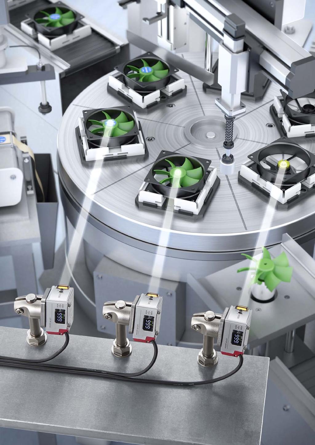
2 PRESENCE AND ABSENCE Part detection in a mould or die Rounded target detection on a moving conveyor WHAT IS A FULL-SPECTRUM SENSOR? A Full-Spectrum sensor features unmatched detecting capabilities that allow it to complete the simplest to the most complex applications with ease. The LR-W Series is one such sensor that can truly handle the Full-Spectrum of applications. Product differentiation based on appearance Product treatment/coating verification PRODUCT DIFFERENTIATION 2


3 REGISTRATION MARKS Registration mark detection on film Registration mark detection on a rounded surface White LED NEW Self-Contained Full-Spectrum Sensor LR-W Series Adjustable Beam Spot Range Up To 500 mm Confirming proper colour shade Differentiating very similar colour COLOUR VERIFICATION 3
4 4


5 UNMATCHED DETECTION CAPABILITIES Superior Full-Spectrum Detecting Capabilities 500 mm Range with Adjustable Beam Spot Automatic Light Power Control for Stable Detection EASE-OF-USE One Touch Calibration User-Friendly Display Easy Integration into Any Setup DURABILITY Robust Metal Housing Water Resistant Dustproof 5


6 UNMATCHED DETECTING CAPABILITIES Full-Spectrum Detection WHITE LED RED LED Unlike conventional sensors which only use a Red LED, the LR-W utilises a White LED and the full colour spectrum. By doing this, the LR-W can reliably and stably differentiate a much wider range of targets. Spectrum of Light Examples of targets the LR-W can stably detect Targets with Slight Colour Changes Metal Targets Tilted Targets High Power White LED and Automatic Power Control By utilising a High Powered White LED, the LR-W ensures detection of dark targets. For glossy targets, the LR-W features an Automatic Power Control function that optimises the sensor's power and sensitivity to ensure stable detection. Detecting Dark Targets Detecting Glossy Targets *10 ms or slower response time is required for Automatic Power Control 500,000 High Dynamic Range 6


7 Superior Detecting Distance with Adjustable Spot Minimum spot 3.5 mm 9 mm 18 mm 30 mm 100 mm 250 mm 500 mm Easy Spot Adjustment 500 mm Detecting Range With an impressive 500 mm range, the LR-W is able to solve applications that were once considered out of reach. The LR-W also features an easy to adjust spot that can be widened or focused to provide the best detection based on the target. These two features combine to make the LR-W a truly all-purpose solution. Auto Tuning Ensures Best Detection Method AUTO TUNING Colour Brightness COLOUR COLOUR + INTENSITY Surface Finish By using the Auto Tuning function, the LR-W accounts for a target's colour, brightness, and surface finish to determine which detection method is best suited for the given application. This helps to ensure stable detection regardless of target variations. 7
, Two Point (2-P), and Master Calibration.")
 Calibration.")

8 EASE-OF-USE Simplified Calibration The LR-W can easily perform three different types of calibration. Users can choose from One-Point (1-P), Two Point (2-P), and Master Calibration. Product Differentiation Registration Mark Detection Varying Colour Detection 1-P Calibration AUTO TUNING 2-P Calibration Master Calibration One simple press is all that is needed to stably match a specific product. Detect difficult registration marks with a simple Two-Point (2-P) Calibration. Innovative tuning option to set clear thresholds for target variation. Products fluttering on conveyor belts Colour variances within products Master Calibration/ Master Addition Calibration Colour inconsistencies, vibration, worn surfaces, and tilting or angling of targets can all lead to unstable detection. Master Calibration allows user's to teach the sensor these variations in advance. Master Addition Calibration enables conditions to be easily added as they arise. 8
9 Intuitive Display and Indicators Clear Display Highly Visible Indicator The LR-W features a highly visible 7-segment display that provides constant feedback, as well as indicators to show detection mode and stability. The highly visible indicator is bright and can clearly be seen from long distances. Seamless Integration Bipolar Outputs NPN PNP M12 Quick Disconnect Same model NPN/PNP switching output The LR-W has selectable NPN or PNP outputs in the same unit, making it easy to standardise on different machine types. The LR-W Series offers a standard M12 4-pin quick disconnect option for easy wiring. Standard Mounting Holes Adjustable Brackets 25.4 mm The LR-W features a standard mounting pitch of 25.4 mm, allowing it to easily mount on existing brackets. If flexible mounting is required, an adjustable mounting bracket is also available. 9


10 DURABILITY High Environmental Resistance Washdown Resistant Dust and Dirt Resistant The LR-W Series meets the requirements of IP65 and IP67 for areas requiring washdown. These IP Ratings also allow the LR-W to perform in dusty or dirty environments. Robust Housing Die Cast Metal Housing Secure Mounting The die cast metal housing can withstand impact from products, tools, or workers. The rigid metal housing of the LR-W allows for secure mounting without the fear of damage to the unit. 10


11 Additional Lineup LR-W70(C) : LR-W Series Small/Dual Spot Model When precise detection is necessary: Small Targets Complex Reg. Marks P.12 Difficult Assemblies LR-WF10(C) : LR-W Series Fibre Extension Model When unique mounting is required: Limited Space Harsh Environment P.14 Versatile Options MU-N Series : Multi-Sensor Controller When additional functionality is needed: Multiple Outputs Analogue P.16 Networking LR-Z & LR-T Series: Position Based Sensor Series When colour/ contrast needs to be ignored: Position Based Long Range P.17 Unaffected by Appearance 11


12 LR-W70(C) LR-W Series Small/Dual Spot Model When precise detection is necessary: The small spot and dual spot options allow for versatile and stable detection. Detection Range 30 to 70 mm Small Spot Size: mm One Spot Mode Small Spot Detection By utilising the one spot detection mode, it is possible to easily detect/confirm the appearance of smaller targets. Confirmation of proper chip orientation Weld seam detection on metal coil stock 12


 - Correct part OK NG NG Difficult Marks: Ignore design variables No Marks:")
13 Dual Spot Detection The innovative usage of dual spot technology provides a level of precise appearance detection that has never been seen before. The LR-W70(C) also offers two unique sensing styles when using Dual Spot Detection. Difference Monitoring Detect target variations by monitoring the difference in appearance between the two spots without the need for calibration. OFF ON No Tuning OFF ON Immediately detect registration marks without calibrating No calibration necessary even when switching targets 2-Point Matching Complex or precise appearance detection is now possible by matching not one, but two spots. Complex Registration Marks Correct Combination Detection ( Silver Pin ) - Correct Part ( Gold Washer ) - Correct part OK NG NG Difficult Marks: Ignore design variables No Marks: Identify repeating patterns Ensure proper combination of two components by referencing two spots individually. 13


14 LR-WF10(C) LR-W Series Fibre Extension Model Compatible Fibre Units P When unique mounting is required: The versatile fibreoptic lineup ensures detection in any situation. Benefits of Fibre Extension Small Size Heads Fibreoptics enable detection in locations that are too tight for conventional sensors. Accessible Controls Simple and accessible remote programming is possible when using fibreoptic heads. Versatile Options High temperature, high flex, and numerous mounting options are all available in the extensive fibreoptic lineup. 14


 Mounting on machines with continuous motion is no")
 Innovative head")
15 Mounting Constraints Require a Small Spot and Small Head Through the use of built-in or attachable lenses, certain fibre heads are able to achieve exceedingly small spots for detection. APPLICABLE HEADS FU-20: Spot Diameter: 0.1 mm, Focal Distance: 5 mm FU-10: Spot Diameter: 0.9 to 3.5 mm, Focal Distance: 10 to 30 mm FU-35FZ w/ F-2HA Lens: Spot Diameter: 0.4 mm, Focal Distance: 7±2 mm Environmental Concerns Guarded (FU-40G, FU-35FG) Stainless steel guarding prevents damage due to crushing or pinching. High Temp (FU-83C) Operate stably in environments of up to 300ºC. High Flex (FU-49U) Mounting on machines with continuous motion is no longer a concern. Unique Application Needs Side View (FU-31, FU-35TZ) Innovative head designs allow for unobtrusive mounting in tight spaces. Area Beam (CZ-12) Monitoring an area provides stable detection of non-repeatable targets. Definite Reflective (FU-40S) Ignore any appearance changes that do not occur within a designated window. 15

 4 to 20 ma or 0 to 10 V Value at ON Peak during ON The MU-N Series controller offers customisable I/O.")


16 MU-N Series Multi-Sensor Controller When additional functionality is needed: Increased I/O, network compatibility, and more, further expand the sensor's capabilities. The LR-W Series can be connected to the MU-N to allow for increased functionality. Various Output Options Rich OLED Display Selectable I/O Analogue 1 Output (16 banks) Parallel 4 Outputs (2 banks) Binary 15 Outputs (No bank) 4 to 20 ma or 0 to 10 V Value at ON Peak during ON The MU-N Series controller offers customisable I/O. This includes both control outputs and a voltage/current analogue output. The combination of an OLED and 7-Segment Display allows users to quickly view data in real time. The MU-N also has the ability to display live graphs for easy machine monitoring. Network Compatibility Settings Back-Up Function Backs up setting information Sensor Replacement Enable copying and writing of data via wide varieties of communication protocols. Copies the setting to a new sensor By pairing the MU-N Series with the KEYENCE NU Series, users can transmit data over a standard industrial network. Compatible networks include EtherNet/IP, EtherCAT, and PROFINET. The Settings Back-Up Function allows users to save sensor settings on the MU-N and quickly transfer them to new sensors that are attached. 16


17 LR-Z & LR-T Series Position Based Sensor Series When colour/ contrast needs to be ignored: Distance-based measuring principles enable stable presence detection of any object. LR-Z Series Part presence regardless of varying colours LR-T Series Welding cell target detection LR-T Series Metal level detection LR-Z SERIES CMOS Laser Sensors LR-Z Detecting Distance (35 to 250 mm) Best in class detecting ability Transparent object detection Stainless steel body with IP69K rating LR-T SERIES TOF Laser Sensors LR-T Detecting Distance (0.06 to 5 m) Max. 5 m detecting distance Custom IC for superior detecting capabilities Metal body with IP65/IP67 enclosure rating 17
18 Lineup Type Detecting distance Min. spot diameter Light source Model Weight Cable (2 m) LR-W g Adjustable spot Standard Type 30 to 500 mm ø3.5 mm (at detecting distance of 100 mm) ø9 mm (at detecting distance of 250 mm) ø18 mm (at detecting distance of 500 mm) White LED M12 connector (Cable sold separately) LR-W500C 110 g Cable (2 m) LR-W g Small/Dual Spot Type 30 to 70 mm mm at 50 mm White LED M12 connector (Cable sold separately) LR-W70C 75 g Cable (2 m) LR-WF g Fibre Type Detecting Distance and Min. Spot Diameter Based on Attached Fibre Head (See Pages 21 & 22 for details) White LED M12 connector (Cable sold separately) LR-WF10C 95 g 18
 LR-WA1 *1*2, PMMA, etc.")
19 Mounting bracket Attachment Type Applicable Sensors Model Material/weight Type Applicable Sensors Model Material/weight Standard mounting bracket (M3 screw 2 supplied) LR-W500/ W70/ WF10 OP *1 110 g Lustre canceling attachment LR-W500(C) LR-WA1 *1*2, PMMA, etc. 5 g Small mounting bracket (M3 screw 2 supplied) LR-W70/ WF10 OP *1 50 g Lustre canceling attachment LR-W70(C) LR-WA2 *1*2, PMMA, etc. 7 g Adjustable bracket (M3 screw 2 supplied) LR-W500(C)/ W70(C)/ WF10(C) OP Zinc nickel plating, etc. 110 g *1 When using LR-WA1 or LR-WA2, detecting range may decrease on targets with low reflectance. Perform sufficient checks in the actual installation environment. *2 When using the LR-WA1 or LR-WA2, the enclosure rating (IP65/IP67) is not met. Adjustable bracket locking screw (105 mm) OP Iron nickel plating 140 g *1 The 4-pin M12 connector type may not be mounted in the orientation shown in the picture (connector downward). Confirm the dimensions and surroundings carefully. Cable Appearance Cable material Sensor side Cable end Length Model Weight 2 m OP g Cable: PVC (Polyvinyl chloride) 5 m OP g M12 4-pin straight 10 m OP g Cable: PUR (Polyurethane) 2 m OP g 10 m OP g Loose wires 2 m OP g Cable: PVC (Polyvinyl chloride) 5 m OP g M12 4-pin L-shape 10 m OP g Cable: PUR (Polyurethane) 2 m OP g 10 m OP g 19
 5 inputs max.* Expansion unit MU-N12 70 g *Six I/O wires available, see instruction manual for applicable wire allocations.")
20 Controller Type Control output External input Analogue output Model Weight Main unit 1 output max.* MU-N11 70 g 4 standard outputs max.* (15 signal combinations available using binary logic) 5 inputs max.* Expansion unit MU-N12 70 g *Six I/O wires available, see instruction manual for applicable wire allocations. Power supply cable for MU-N Series Cable is not included with the controller. Must be purchased separately. Appearance Applicable unit Cable material Cable end Controller side Length Model Weight 8-core loose wires MU-CB8 150 g Main unit 4-core loose wires MU-CB4 120 g 2 m 6-core loose wires MU-CB6 130 g Expansion unit 2-core loose wires MU-CB2 100 g PVC (Polyvinyl chloride) Connector Main unit M12 4-pin straight 0.3 m MU-CC4 30 g Sensor-to-controller cable (for 4-pin M12 connector type) Appearance Cable material Sensor side Controller side Length Model Weight PVC (Polyvinyl chloride) M12 4-pin straight M12 4-pin L-shape Connector 2 m OP g 10 m OP *1 280 g 2 m OP g 10 m OP *1 280 g *1 The 10 m cable includes one spare connector for the controller side. Connector set for sensor-to-controller connection This set is required when the sensor cable end is loose wires or when the sensor-to-controller cable is cut. Appearance Type Applicable model Model Weight For PVC (Polyvinyl chloride) cable LR-W500, LR-W70, LR-WF10 OP-75721/87272/85502 OP-75722/87273/87274 OP g For PUR (Polyurethane) cable OP-87636/87637 OP-87640/87641 OP g Controller mounting options Appearance Type Description Model Weight Mounting adapter (for main unit) Allows the main unit to be mounted without a DIN rail. OP g End unit (for expansion) Used to secure the main and expansion units to DIN rail from both ends. End units must be used when an expansion unit is connected. (2 pieces included) OP g 20
 -40 to +50 C 1 m Free-cut (ø1.3 2) -40 to +50 C 18.")

 -40 to +50 C Thickness: 5.")
21 Fibre unit specification when using LR-WF10(C) Unit: mm Feature Type Fibre unit length (Diameter) Ambient temperature Appearance Minimum bend radius Detecting distance Model Weight Threaded and Hex-shaped Fibres M3 Hex-shaped Coaxial M3 Threaded Coaxial 1 m Free-cut (ø1.3 2) -40 to +50 C 1 m Free-cut (ø1.3 2) -40 to +50 C 18.5 M3 17 M3 R2 ToughFlex 500 ms: ms: ms: 12 1 ms: μs: 5 FU-35TZ 7 g FU-35FZ 6 g Cylinder (Set Screw Installation) Diameter ø2 1 m Free-cut ø to +50 C 10 ø2 R2 ToughFlex High-flex 500 ms: ms: ms: 9 1 ms: μs: 3 FU-49U 4 g Beam spot diameter ø0.9 to 3.5 Focal distance 10 to 30 2 m Free-cut (ø1.3 2) -40 to +70 C M to to 30 FU-10 5 g Small Spot Reflective Beam spot diameter ø0.1 Focal distance 5 50 cm cut not allowed. -40 to +70 C Tip: ø3 18 R25 5 ± 1 *1 FU-20 2 g Focused Beam/ High-power Aperture angle: 8 2 m Free-cut (ø2.2 2) -40 to +50 C Thickness: R2 ToughFlex 500 ms: 26 to ms: 27 to ms: 33 to ms: 250 μs: FU g Definite-reflective Thin, Small 2 m Free-cut (ø2.2 2) -40 to +70 C 7.4 R ms: 2 to ms: 3 to ms: 10 to 93 1 ms: 12 to μs: 13 to 68 FU-40S 25 g Sleeve Side view detection 2 m Free-cut (ø1.0 2) ø2.8 ø2-40 to +70 C 15 R ms: ms: ms: 7 1 ms: μs: 2 FU-31 5 g Do not bend sleeve. Heat Resistant Heat resistant temperature *2 : 300ºC 1 m cut not allowed. -40 to +300 C ø M4 10 R ms: ms: ms: 40 1 ms: μs: 16 FU-83C 23 g *1 Cannot be used with the response time of 250 μs and 1 ms. *2 Use the fibre sensor under dry conditions. Allow some margin for the temperature upper limit when selecting a heat-resistant fibre unit. 21
22 Lens + Fibre Unit Type Beam spot diameter Focal distance Unit: mm Lens Fibre units Model Appearance Weight Minimum bend radius Appearance Model -30 to +70 C R2 ToughFlex FU-35FZ Small spot ø0.4 7 ±2 F-2HA Tip: ø g R2 ToughFlex -30 to +70 C R2 ToughFlex FU-35TZ FU-35FZ ø ±2 F-4HA Tip: ø g R2 ToughFlex FU-35TZ Side-view adjustable spot ø0.5 to ø3 8 to 30 F-5HA -30 to +70 C 8.7 R2 ToughFlex FU-35FZ 2 g CZ Series unit Unit: mm Type Smallest spot diameter Detection range Model Appearance Minimum bend radius Enclosure rating Weight 2 m Free-cut -40 to +70 C Small size adjustable spot ø0.9 to ø to 30 CZ-10 5 g Small size, side-view adjustable spot ø0.9 to ø1.5 3 to 15 CZ-11 1 m -40 to +70 C IP40 13 g Long detection distance, small beam spot ø2 35 ±3 CZ-13 1 m -40 to +70 C R25 20 g 2 m Free-cut -40 to +70 C Long detection distance ø6 70 ±20 CZ-40 Small beam spot ø1 16 ±4 CZ-41 2 m Free-cut -40 to +70 C R15 IP67 27 g 2 m Free-cut -40 to +70 C Area beam spot, reflective 5 to 20 CZ g Transparent object differentiation, retro-reflective Reflector R-2: 40 to 1000 R-3: 40 to 500 R-5: 40 to 300 CZ-60 2 m Free-cut -20 to +55 C R25 23 g 22
23 Sensor specifications Type Standard Type Small/Dual Spot Type Fibre Type 2 m cable type LR-W500 LR-W70 LR-WF10 Model M12 connector 4-pin type LR-W500C LR-W70C LR-WF10C Detecting distance 30 to 500 mm 30 to 70 mm Min. spot diameter Response time *1 Light source Mutual interference reduction function Timer Power voltage Power supply Current consumption *3 Adjustable spot ø3.5 mm at 100 mm ø9 mm at 250 mm ø18 mm at 500 mm 200 μs/1 ms/10 ms/100 ms/500 ms selectable 65 ma or less (without load) at 24 VDC; 120 ma or less (without load) at 12 VDC mm at 50 mm 1-Spot Mode: 200 μs, 1 ms, 10 ms, 100 ms, 500 ms selectable 2-Spot Mode, Difference Monitoring: 500 μs, 2.5 ms, 20 ms, 200 ms, 999 ms selectable 2-Spot Mode, 2-Point Matching: 400 μs, 2 ms, 20 ms, 200 ms, 999 ms selectable White LED Up to 2 units when alternate frequencies set OFF/ON delay/off delay/one-shot 10 to 30 VDC, including 10% ripple (P-P), Class 2 or LPS 60 ma or less (without load) at 24 VDC; 110 ma or less (without load) at 12 VDC Detecting Distance and Min. Spot Diameter Based on Attached Fibre Head (See Pages 21 & 22 for details) 250 μs, 1 ms, 10 ms, 100 ms, 500 ms Selectable * 2 50 ma or less (without load) at 24 VDC; 90 ma or less (without load) at 12 VDC I/O *4 External input Tuning /laser emission stop selectable, Short circuit current: 1 ma or less for NPN/2 ma or less for PNP For the applied voltage, see the wiring diagrams in the instruction manual. For the input times, see the time charts in the instruction manual. Control output NPN open collector/pnp open collector selectable, 30 VDC or less, 50 ma or less, remaining voltage: 2 V or less, N.O./N.C. selectable Protection circuit Protection against reverse power connection, power supply surge, output overcurrent, output surge, and reverse output connection Enclosure rating IP65/IP67 (IEC60529) IP65 (IEC60529) *5*6 Ambient light Incandescent lamp: lux or less, Sunlight: lux or less Environmental Ambient temperature -20 to +50 C (no freezing) -20 to +45 C (no freezing) resistance Ambient humidity 35 to 85%RH (no condensation) Shock resistance 1000 m/s 2 in X, Y, Z axis directions respectively 6 times Vibration resistance 10 to 55 Hz Double amplitude 1.5 mm in the X, Y, Z axis directions respectively, 2 hours Case: Zinc die cast (Nickel chrome plating), Indicator cover: PPSU, s: PES, Lens cover (except for Fibre type) and display: PMMA (scratch-resistant coating), Cable bushing: PBT Material Cable (2 m cable type only): PVC, Spot adjustment dial(standard type only): Iron (triiron tetraoxide coated), Connector ring (4-pin M12 connector type only): PMP, Connector socket (4-pin M12 connector type only) : PEI, Fibre locking mount (Fibre type only): PBT, NBR, Silicone rubber,, SUSXM7 Adapter (Fibre type only): PBT Weight 2 m cable type 170 g (including cable) 130 g (including cable) 150 g (including cable) M12 connector 4-pin type 110 g 75 g 95 g *1 When alternate frequencies are set, the response time increases by approximately 20%. *2 When using the IO-Link communication, if the response time is set in 1ms or more, it becomes approximately 10% slower. *3 Standard type: 195 ma or less (at 10 V, with load), Small/Dual Spot type: 180 ma or less (at 10 V, with load), Fibre type: 160 ma or less (at 10 V, with load) *4 IO-Link : Specification v.1.1/com2 (38.4 kbps) is supported. The setup file can be downloaded from KEYENCE website ( you are using the product in an environment in which you cannot download files over the Internet, contact your nearest KEYENCE office. *5 When the following small-diameter fibre units (the diameter of the cable is ø1.3 mm or ø1.0 mm) are used, the IP65 rating cannot be satisfied (FU-4F/66/91/93/43/63/63T etc.). When any small-diameter fibre units except for the above are used, IP65 is applied. *6 In any of the following cases, the IP65 enclosure rating cannot be satisfied. When the waterproof adapter A/B are not used at the time of installation of a small-diameter fibre unit. LR-W500(C) Reference data of distance vs. spot diameter (Typical) Focused at 100 mm Focused at 200 mm Focused at 300 mm Focused at 400 mm Focused at 500 mm Reference for minimum spot diameter Spot diameter 50 (mm) Distance (mm) I/O circuit Diagrams Control output circuit Input circuit When NPN is selected When NPN is selected ➀Brown 10 to 30 VDC ➀Brown 10 to 30 VDC Main circuit Overcurrent protection circuit ➃Black ➂Blue Load 0 V Main circuit ➁White ➂Blue PLC, etc. 0 V When PNP is selected ➀Brown 10 to 30 VDC When PNP is selected ➀Brown 10 to 30 VDC M12 Connector pin layout Main circuit Overcurrent protection circuit ➃Black ➂Blue Load 0 V Main circuit ➁White ➂Blue PLC, etc. 0 V
24 Controller specifications MU-N11 MU-N12 Model Main unit Expansion unit Connected sensor LR-W500(C) LR-W70(C) LR-WF10(C) LR-W500(C) LR-W70(C) LR-WF10(C) Response time Mutual interference reduction function Timer Power voltage Power supply I/O Current consumption Control output External input Single output: 300 μs/1.1 ms/11 ms/ 100 ms/500 ms selectable Multiple output: 2 ms/3 ms/11 ms/ 100 ms/500 ms selectable 135 ma or less (without load) 335 ma or less (when 4 outputs are used, with load) 1-Spot Mode Single output: 300 μs/1.1 ms/11 ms/ 100 ms/500 ms selectable 2-Spot Mode Difference Monitoring: 600 μs/2.6 ms/21 ms/ 200 ms/1 s selectable 2-Spot Mode 2-Point Matching: 500 μs/2.1 ms/21 ms/ 200 ms/1s selectable 1-Spot Mode Multiple outputs: 2 ms/3 ms/11 ms/100 ms/ 500ms selectable 2-Spot Mode Multiple outputs: 2 ms/4 ms/21 ms/200 ms /1 s selectable 130 ma or less (without load) 330 ma or less (when 4 outputs are used, with load) Single output: 350 μs/1.2 ms/13 ms/ 120 ms/600 ms selectable Multiple output: 3 ms/4 ms/14 ms/ 120 ms/600 ms selectable Single output: 300 μs/1.1 ms/11 ms/ 100 ms/500 ms selectable Multiple output: 2 ms/3 ms/11 ms/ 100 ms/500 ms selectable Up to 2 units with alternate frequencies set OFF/OFF delay/on delay/one-shot 24 VDC, ripple (P-P) 10% or less, Class 2 or LPS 120 ma or less (without load) 320 ma or less (when 4 outputs are used, with load) 120 ma or less (without load) 200 ma or less (when 4 outputs are used, with load) 4 outputs max. NPN open collector/pnp open collector selectable 24 VDC or less, main unit: 50 ma or less *1, expansion unit: 20 ma or less Remaining voltage: 2 V or less N.O./N.C. selectable 5 inputs max. Short circuit current: 1 ma or less for NPN/2 ma or less for PNP For the applied voltage, see the wiring diagrams in the instruction manual. 1-Spot Mode Single output: 300 μs/1.1 ms/11 ms/ 100 ms/500 ms selectable 2-Spot Mode Difference Monitoring: 600 μs/2.6 ms/21 ms/ 200 ms/1 s selectable 2-Spot Mode 2-Point Matching: 500 μs/2.1 ms/21 ms/ 200 ms/1s selectable 1-Spot Mode Multiple outputs: 2 ms/3 ms/11 ms/100 ms/ 500 ms selectable 2-Spot Mode Multiple outputs: 2 ms/4 ms/21 ms/200 ms /1 s selectable 115 ma or less (without load) 195 ma or less (when 4 outputs are used, with load) Analogue output 1 output max. Current output/voltage output selectable Current output: 4 to 20 ma Maximum load resistance: 450 Ω Voltage output: 0 to 10 V External load resistance: 5 kω or more Protection circuit Protection against reverse power connection, power supply surge, output overcurrent, output surge, and reverse output connection Unit expansion Up to 4 units per main unit *2 Ambient temperature -20 to +50 C (no freezing) Environmental Ambient humidity 35 to 85%RH (no condensation) resistance Shock resistance 1000 m/s 2 in X, Y, Z axis directions respectively 6 times Vibration resistance 10 to 55 Hz Double amplitude 1.5 mm in the X, Y, Z axis directions respectively, 2 hours Material Case and dust cover: Polycarbonate, : Polyacetal, Display panel: Acrylic Weight 70 g *1 20 ma or less when an expansion unit is connected. *2 Up to 5 N-bus devices, including the main unit (or network unit), can be linked together. Single output: 350 μs/1.2 ms/13 ms/ 120 ms/600 ms selectable Multiple output: 3 ms/4 ms/14 ms/ 120 ms/600 ms selectable 105 ma or less (without load) 185 ma or less (when 4 outputs are used, with load) I/O circuit diagrams Control output circuit When NPN is selected Brown*(➀) 24 VDC Input circuit Analogue output circuit * Pin layout When NPN is selected when the M12 connector (4-pin) Brown*(➀) Brown(➀) 24 VDC 24 VDC cable is used Main circuit Overcurrent protection circuit Black(➃)/White(➁)/ Orange/Grey (When control output is selected) Blue*(➂) Load 0 V Main circuit White (➁)/Orange/ Grey/ Pink/Violet (When external input is selected) Blue*(➂) PLC, etc. 0 V Main circuit Analogue current / voltage output circuit White (➁) (When analog output is selected) Analogue input device Blue(➂) 0 V When PNP is selected Main circuit Overcurrent protection circuit * MU-N11 only Brown*(➀) 24 VDC Black(➃)/White(➁)/ Orange/Grey (When control output is selected) Blue*(➂) Load 0 V When PNP is selected Main circuit Brown*(➀) 24 VDC White (➁)/Orange/ Grey/Pink/Violet (When external input is selected) Blue*(➂) PLC, etc. 0 V Power Cable wire colours MU-N11 (main unit) Wire colour Details Brown (1*) 24 V Blue (3*) 0 V Black (4*) Output 1 White (2*) Orange Output 2/ Input 1/ Analogue Output 3/ Input 2 Power cable model/type MU-CB4 4-core cable for main unit (MU-CC4:M12 connector type)* MU-CB8 8-core cable for main unit Grey Output 4/ Input 3 Pink Input 4 Violet Input 5 * Pin numbers when using an M12 connector cable MU-N12 (expansion unit) Wire colour Details Power cable model/type Black Output 1 MU-CB2 White Output 2/ 2-core cable Input 1 for expansion unit MU-CB6 Orange Input 2 cable for Output 4/ Grey expansion Input 3 unit Output 3/ 6-core Pink Input 4 Violet Input 5 24
25 Dimensions Unit: mm LR-W500 Dial LR-W500C Dial Indicator 13 Indicator emitted light received light Reference surface for detecting distance 2 ø ø4.0, 4-core Brown/ Blue/Black/White 0.20 mm2 Cable length: 2 m STB C I Display emitted light received light Reference surface for detecting distance 2 ø STB C I Pin layout Display M12 connector OP OP LR-W500 Angle non-adjustable area when OP is used ø (6-R2.25) 42 2-R Plate thickness: 3 ø R2 (4-R1.75) (33.4) R4 Plate thickness: 3 2-M3 0.5 emitted light Reference surface for detecting distance emitted light received light Non-adjustable area Rotational centre of main body Non-adjustable area (50 ) (50 ) Nonadjustable area Nonadjustable area OP OP LR-W500 OP OP LR-W500 Hexagon socket head cap screw (M5, Length: 15, Across flats: 4, Iron nickel plating) ø ø22 4 M3 P= ø20.1, ø24 spot facing depth: Reference surface for detecting distance emitted light Reference surface for detecting distance Nut (M5, Iron nickel plating) emitted light received light received light Zinc nickel plating
26 Dimensions OP LR-WA1 + LR-W500 When OP OP LR-W500C + L-shape type M12 connector are used Warning for when an M12 connector type is used 2 ø24, thickness: 2.5 (40) M12 P (24.6) Reference surface for detecting distance Rotational centre of main body R23.5 When mounting the unit as shown in the figure below (connector downward), carefully check the surroundings for any objects that might interfere with the connector cable. ø12 emitted light received light 105 Across flats: 18, thickness: 10 Iron nickel plating (48.1) (38.1) 33.7 (R73.9) R23.5 LR-W70 LR-W70C Indicator 13 Indicator emitted light 1 emitted light 2 received light Reference surface for detecting distance 2 ø ø4.0, 4-core Brown/ Blue/Black/White 0.20 mm 2 Cable length: 2 m STB C I 5.35 Display emitted light 1 emitted light received light 12.5 Reference surface for detecting distance 2 ø STB C I 5.35 Display 10.9 M12 connector OP OP LR-W70 Angle non-adjustable area when OP is used ø (6-R2.25) 42 2-R Plate thickness: 3 ø R2 (4-R1.75) (33.4) R4 Plate thickness: 3 2-M emitted light 1 received light emitted light 2 Reference surface for detecting distance Non-adjustable area Rotational centre of main body Non-adjustable area (50 ) (50 ) Nonadjustable area Nonadjustable area 26
27 Unit: mm OP OP LR-W70 Angle non-adjustable area when OP is used (4) 11 2-R emitted light 1 received light emitted light R8 emitted light 2 emitted light 1 Reference surface for detecting distance (62 ) (62 ) (33.4) R4 2-M3 0.5 received light Non-adjustable area Non-adjustable area (62 ) (62 ) Non-adjustable area Non-adjustable area t = 2.0 t = 3.0 OP OP LR-W70 OP OP LR-W70 Hexagon socket head cap screw (M5, Length: 15, Across flats: 4, Iron nickel plating) 4 M3 P= ø20.1, ø24 spot facing depth: ø ø22 Nut (M5, Iron nickel plating) Reference surface for detecting distance emitted light 1 emitted light Reference surface for detecting distance emitted light 1 emitted light received light received light Zinc nickel plating OP LR-WA2 + LR-W70 When OP OP LR-WF70C + L-shape type M12 connector are used 2 ø24, thickness: 2.5 ø Across flats: 18, thickness: 10 (40) Iron nickel plating M12 P Indicator Reference surface for detecting distance emitted light 1 emitted light received light (32.3) (19.9) 29 (R73.9) Rotational centre of main body R Warning for when an M12 connector type is used When mounting the unit as shown in the figure below (connector downward), carefully check the surroundings for any objects that might interfere with the connector cable R
28 Dimensions LR-WF10 LR-WF10C Indicator 13 Indicator (14) (14) T R ø ø4.0, 4-core Brown/ Blue/Black/White 0.20 mm2 Cable length: 2 m STB C I 45 Display T R ø STB C I Display M12 connector OP OP LR-WF ø (6-R2.25) 2-R ø R (4-R1.75) 67 (33.4) R T R M Plate thickness: 3 Plate thickness: 3 OP OP LR-WF (4) 2-R R (33.4) R T R t = t = M
29 Unit: mm FU-10 Free-cut FU-20 Two-sided Chamfering ø6 A M6, P=0.75 mounting part M6 nut, M6 washer, tooth locked washer provided. Transmitter ø2.75 lens ø3 ø1.6 Transmitter 5.2 A ø5.5 lens A-A * 2.6 cross L section view L: lens unit length * Adjustable part 4.2 to ø1.3 2 (Adaptor A) * * Set-screw tightening area FU-31 Free-cut FU-35FZ Free-cut ø2 ø2.8 ø1.0 2 (Adaptor B) ø0.5 core fibre Across-flats: 5.4, t=2 M3, P=0.5 SUS303 ø1.3 2 (Adaptor A) ø0.265 core fibre 12 5 ø FU-35TZ Free-cut 8.1 M3, P=0.5 Effective screw length: 12 Nickel-plated brass ø0.5 core fibre ø1.3 2 (Adaptor A) FU-40 Free-cut ø3.7 2 ø2.2 2 lens 8 ø0.265 core fibre (M3 nut and washer included) 7 FU-40S Free-cut ø ø3.5, ø6 spot facing FU-49U Free-cut ø0.5 2 core fibre ø2 SUS303 ø1.0 2 (20)* * Do not bend this part. ø * * Do not bend this part FU-83C Across-flats: 7, t=2 ø1.45 ø2.6 core fibre M4, P=0.7 SUS303 ø4.2 Hexagonal clasp ø (-40 to +300 C)* 480 (-40 to +200 C)* 20 (-40 to +70 C)* * Maximum temperature resistance for each part is shown in ( ). F-2HA ø F-2HA + FU-35FZ ø5 Housing: Aluminium Lens: Plastic F-2HA + FU-35TZ F-4HA F-4HA + FU-35FZ ø7.4 ø Housing: Aluminium Lens: Glass F-4HA + FU-35TZ F-5HA 15 ø3.7 lens F-5HA + FU-35FZ ø Housing: Aluminium Lens: Glass L 5 L=2.6 to
30 Dimensions CZ-10 Two-sided Chamfering ø6 A M6, P ø1.3 mounting part Transmitter CZ ø L 5.0 ø4.5 SUS303 ø3.5 ø4.5 SUS A _ A cross section view ø5.5 lens 2.6 A * 3 L 2000 L: Lens unit length *Adjustable part 4.2 to ø3.7 lens M3, P= L: 2.6 to 5.0 Housing: Aluminium (black anodic oxide coating) CZ Slot (Note) ø3.3 ø2.2 2 mounting hole CZ ø3.3 ø2.2 2 mounting hole (Free-cut) (Free-cut) (Note) Detail of slot Mounting bracket (attached to CZ-40/41) When mounting bracket is attached to CZ-40 Slot (Note) (Note) Detail of slot 2-M3 screw t= t=1.2 (32) 45 The sensor head angle can be changed by a maximum of 45 degrees upward and downward. CZ-12 transmitted light beam 2-ø3.3 2-ø2.2 CZ-13 M8 P1.0 ø4.5 SUS303 2 ø (4) ø10.6 Chamfered (2) ø4.5 SUS303 (3.5) ø CZ-60 Beam axis centre ø3.2 Mounting hole C ø2.2 R-2 reflector (attached to CZ-60) Mounting bracket (attached to CZ-60) Flat nut (attached to CZ-60) 2-ø (21.5) M3, P=0.5 6 t=1.5 t=
31 Unit: mm MU-N11 (Main unit) MU-N12 (Expansion unit) Maximum when cover is open: 108 MAX. 135 Maximum when cover is open: 108 MAX. 135 (41.9) (41.9) PVC: 8.9 min. PVC: 8.9 min. PUR: 28.2 min. PUR: 28.2 min min min. When mounting adapter is attached (OP-76877, optional, sold separately) When the communication unit is connected without using a power supply cable ø3.4 Maximum when cover is open: 108 MAX ( ) (41.9) Back of mounting adapter PVC: 8.9 min. PUR: 28.2 min. When expansion units are connected End unit (OP-26751, optional, sold separately) 6 End unit End unit *1 When mounted on a DIN rail (22.6) L 6 *1 End units must be used when an expansion unit is connected. (Optional) No. of expansion units L
32 Dimensions Unit: mm M12 connector cable for sensor OP-75721/87272/85502 OP-75722/87273/87274 M12 43 OP-75721:2000/OP-87272:5000/OP-85502: OP-75722:2000/OP-87273:5000/OP-87274:10000 ø14 M12 ø ø4.0 ( mm 2 ) ø4.0 ( mm 2 ) OP-87636/87637 OP-87640/87641 M12 44 OP-87636:2000/OP-87637:10000 ø14.8 M12 8 OP-87640:2000/OP-87641:10000 ø ø4.7 ( mm 2 ) 34.5 ø4.7 ( mm 2 ) Pin layout No. ➀ ➁ ➂ ➃ Colour Brown White Blue Black Power supply cable for MU-N MU-CB8/CB4/CB6/CB2 MU-CC ø14 MU-CB8 :ø5.5 ( mm 2 ) MU-CB4:ø5.5 ( mm 2 ) MU-CB6:ø5.5 ( mm 2 ) MU-CB2:ø5.5 ( mm 2 ) ø5.5 ( mm 2 ) M12 M12 Connector pin layout No. ➀ ➁ ➂ ➃ Colour Brown White Blue Black Sensor-to-controller cable (4-pin M12 connector type) OP-88025/88026 OP-88027/88028 M12 43 OP-88025:2000OP-88026:10000 ø OP-88027:2000/ OP-88028:10000 M12 ø ø4.0 ( mm 2 ) ø4.0 ( mm2) X M12 Connector pin layout X ➀ ➁ ➂ ➃ Y ➀ ➁ ➂ ➃ Colour Brown White Blue Black Y Connector pin layout ➀ ➁ ➂ ➃ X M12 Connector pin layout X ➀ ➁ ➂ ➃ Y ➀ ➁ ➂ ➃ Colour Brown White Blue Black Y Connector pin layout ➀ ➁ ➂ ➃ Warning for when an L-shape type M12 connector is used When the L-shape type M12 connector is used, the cable is fixed in the direction shown in the right figure. The connector base cannot be rotated. CAD DATA DOWNLOAD 32
 cable 0.")
33 Network communication unit NU Series Open field network unit Options Type Appearance Network Model Model Type OP STP (Shielded twisted-pair) cable 0.2 m EtherNet/IP TM NU-EP1 OP STP (Shielded twisted-pair) cable 0.5 m Communication unit EtherCAT NU-EC1 OP OP STP (Shielded twisted-pair) cable 1 m STP (Shielded twisted-pair) cable 3 m OP STP (Shielded twisted-pair) cable 5 m PROFINET NU-PN1 OP STP (Shielded twisted-pair) cable 10 m The NU Series models also have the following communication units: CC-Link-compatible NU-CL1 and DeviceNet TM -compatible NU-DN1. EtherNet/IP TM compatible communication unit: NU-EP1 Model Ethernet specifications EtherNet/IP TM specifications Sensor connection specifications Power voltage Compliant standards Transmission rate Transmission media Maximum cable length Maximum number of connectable hubs*2 NU-EP1 IEEE802.3 (10BASE-T) IEEE802.3u (100BASE-TX) IEEE802.3af (Power over Ethernet, Class3) 10 Mbps (10BASE-T) 100 Mbps (100BASE-TX) STP or Category3 or higher UTP (10BASE-T)*1 STP or Category5 or higher UTP (100BASE-TX) 100 m (between this unit and Ethernet switch) 4 (10BASE-T) 2 (100BASE-TX) Supported functions Cyclic communication Message communication (Explicit message communication) supporting UCMM and Class 3 Number of connections 64 RPI (communication cycle) 0.5 to ms (Unit: 0.5 ms) Tolerable communication bandwidth for cyclic 6000 pps communication Conformance test Version A7 supported Connectable sensor N-bus sensor amplifier*3 Number of connectable sensors 16 units max.*4 Power supply Supplied from this unit via the sensor amplifier connector Allowable passing current* ma or less total PoE power supply*6 Supplied voltage: 24 V±10%, supplied current: 360 ma or less*7 24 VDC±10%, ripple (p-p) 10% or less (when the power supply connector is used) 48 VDC (57 VDC max.) (when PoE power supply is used) 1500 mw or less (60 ma or less at 24 V)*8 80 g Power consumption Weight (including connector) Accessories Instruction manual, power supply connector, end unit 2 * The following KEYENCE PoE power supply units cannot be connected: [DT-100A] [DT-500] [NE-V08] *1 Use an STP cable or a Category5 or higher UTP cable for the connection using PoE power supply function. *2 When a switch is used, there is no limit to the number of connectable units. *3 N-bus is the name of KEYENCE's simplified wiring system for sensor amplifiers. *4 Varies depending on the sensor amplifier to be connected. *5 This is the current value that can be supplied to this unit or the sensor amplifier connected to this unit. *6 This is the power that can be supplied to the sensor amplifier when the PoE power supply function is used. *7 Varies depending on the ambient temperature. (-20 to +45 C: 360 ma or less, +45 to +50 C: 260 ma or less, +50 to +55 C: 140 ma or less) *8 Excluding the current supplied to the connected sensor amplifier. 33
34 EtherCAT compatible communication unit: NU-EC1 Model NU-EC1 Compliant standards IEEE802.3u (100BASE-TX) Transmission rate 100 Mbps (100BASE-TX) Ethernet specifications Transmission media Category5e or higher STP Distance between nodes 100 m Communication port RJ-45 2 EtherCAT communication Process data object communication (cyclic communication) Supported functions specifications Mailbox communication (message communication) CoE compatible Connectable sensor N-bus sensor amplifier*1 Sensor connection Number of connectable sensors 16 units max.*2 specifications Power supply Supplied from the unit via a wiring-saving connector Allowable passing current* ma or less total Power voltage 24 VDC ±10%, ripple (p-p) 10% or less Power consumption 1700 mw or less (70 ma max. at 24 V)*4 Weight (including connector) 80 g Accessories Instruction manual, power supply connector, end unit 2 * EtherCAT is a registered trade name of BECKHOFF. *1 N-bus is the name of KEYENCE's simplified wiring system for sensor amplifiers. *2 Varies depending on the sensor amplifier to be connected. *3 This is the current value that can be supplied to this unit or the sensor amplifier connected to this unit. *4 Excluding the current supplied to the connected sensor amplifier. PROFINET compatible communication unit: NU-PN1 Model Ethernet specifications PROFINET specifications Sensor connection specifications Power voltage Compliant Standards Transmission rate Transmission media Maximum cable length NU-PN1 IEEE802.3u (100BASE-TX) 100 Mbps (100BASE-TX) STP or Category5 or higher UTP 100 m Maximum number of connectable hubs 2 Supported functions Cyclic communication (Data I/O communication) Acyclic communication (Record data communication) Number of connectable controllers 1 Update Time 2 to 512 ms Version of GSDML Version 2.3 Conformance class Class A supported Conformance test V2.2.4 supported Applicable protocols LLDP, DCP Connectable sensors N-bus sensor amplifier*1 Number of connectable sensors 16 units max.*2 Power supply Supplied from this unit via the sensor amplifier connector Allowable passing current* ma or less total PoE power supply*3 Supplied voltage: 24 V±10%, supplied current: 360 ma or less*4 24 VDC±10%, ripple (p-p) 10% or less (when the power supply connector is used) 48 VDC (57 VDC max.) (when PoE power supply is used) 1500 mw or less (60 ma or less at 24 V)*5 80 g Power consumption Weight Accessories Instruction manual, power supply connector, end unit 2 *1 N-bus is the name of KEYENCE's simplified wiring system for sensor amplifiers. *2 Varies depending on the sensor amplifier to be connected. *3 Indicates the current that can be supplied to the NU-PN1 and to the sensor units linked to the NU-PN1. *4 This is the power that can be supplied to the sensor amplifier when the PoE power supply function is used. *5 Varies depending on the ambient temperature. (-20 to +45 C: 360 ma or less, +45 to +50 C: 260 ma or less, +50 to +55 C: 140 ma or less) *6 Excluding the current supplied to the connected sensor amplifier. 34
35 Dimensions Unit: mm NU-EP1/PN (42.5) (0.2) NU-EC (38.5) 170 max Maximum when the cover is opened 73.6 (0.2) CAD DATA DOWNLOAD 35
 2016 KEYENCE CORPORATION. All rights reserved.")
36 LR-W SERIES Self-Contained Full-Spectrum Sensor Copyright (c) 2016 KEYENCE CORPORATION. All rights reserved. LRW_EU-WW-C2-GB I20
New Standard! All-Purpose Laser Sensor. Multi-Sensor Controller MU-N Series. NEW All-Purpose Laser Sensor LR-T SERIES
 New Standard! All-Purpose Laser Sensor Multi-Sensor Controller MU-N Series NEW All-Purpose Laser Sensor LR-T SERIES All-Purpose Laser Sensor LR-T SERIES 2 A NEW DIMENSION TO ALL-PURPOSE LASER SENSORS The
NEW Self-contained. Photoelectric Sensor PR-M/F SERIES. New Standard! General-Purpose Metal Photoeye. New Standard for Photoelectric Sensors
 New Standard! General-Purpose Metal Photoeye NEW Self-contained Photoelectric Sensor PR-G SERIES New Standard for Photoelectric Sensors 01 02 03 PR-G SERIES PR-M/F SERIES LR-Z SERIES Self-contained Photoelectric
New Standard! All-Purpose Laser Photoeye. NEW Self-contained. CMOS Laser Sensor LR-Z SERIES
 New Standard! All-Purpose Laser Photoeye NEW Self-contained CMOS Laser Sensor LR-Z SERIES S e l f - c o n t a i n e d CMOS Laser Sensor LR-Z SERIES 2 Introducing a more versatile Laser Sensor Detection
NEW Self-contained CMOS Laser Sensor. LR-Z Series ALL-PURPOSE LASER SENSOR. Position, Contrast, & Transparency Detection
 NEW Self-contained CMOS Laser Sensor LR-Z Series ALL-PURPOSE LASER SENSOR Position, Contrast, & Transparency Detection LR-Z Series TRUE DO-IT-ALL SENSOR SIMPLE SET UP UNIVERSAL CHANGE DETECTION (U.C.D.
E3S-A. Built-in Amplifier Photoelectric Sensor (Medium Size) Ordering Information. Built-in Amplifier Photoelectric Sensors. Horizontal. 7 m.
 Ordering Information. Built-in Amplifier Photoelectric Sensors. Horizontal. 7 m.") Built-in Amplifier (Medium Size) ES-A CSM_ES-A_DS_E Be sure to read Safety Precautions on page 0. Ordering Information Built-in Amplifier s Red light Infrared light Sensing method Appearance Connection
Built-in Amplifier (Medium Size) ES-A CSM_ES-A_DS_E Be sure to read Safety Precautions on page 0. Ordering Information Built-in Amplifier s Red light Infrared light Sensing method Appearance Connection
Unaffected by Angle, Colour, or Dirt
 Cat No. PZ-C2 Unaffected by Angle, Colour, or Dirt Introducing Multi-reflective Photoelectric Sensors PZ-V Provide Solutions to All the Problems Experienced with Conventional Reflective Types. Conventional
DFP Series Fiber Photoelectric Amplifiers
 DFP Series Fiber electric Amplifiers Part Number Compact rectangular plastic DIN-rail mount- DC models available DIN-rail mounting 12-turn potentiometer sensitivity setting with illuminated scale NPN or
Self-contained Photoelectric Sensors. PZ-V/M Series
 Self-contained Photoelectric Sensors PZ-V/M Series Unaffected by Angle, Colour, or Dirt Introducing Multi-reflective Photoelectric Sensors PZ-V Provide Solutions to All the Problems Experienced with Conventional
Optimum sensing capability for LCD manufacturing
 SENSORS FOR Glass Substrate Detection Sensor Amplifier-separated FX-301-F FT-F9 FD-F7 EX-F70/F60 HD-T1 M FD-L3 Reliable detection of glass substrates Its unique optical system enables detection of transparent
New Standard! Metal Mini-Photoeye NEW. Self-contained Miniature Photoelectric Sensor PR-M/F SERIES. New Standard for Photoelectric Sensors
 New Standard! Metal Mini-Photoeye NEW Self-contained Miniature Photoelectric Sensor PR-M/F SERIES New Standard for Photoelectric Sensors 01 02 LR-Z SERIES PR-M/F SERIES NEW Self-contained Miniature Photoelectric
Mini Photoelectric Sensor
 Mini Photoelectric Sensor High cost-performance Mini Photoelectric Sensor Saves Installation Space and Wiring Effort and Detects Minute Sensing Objects Pin-point beam (1 to 2-mm dia.) makes it possible
NEW All-Purpose Laser Sensor. LR-Z Series ALL-PURPOSE LASER SENSOR. Position, Contrast, & Transparency Detection
 NEW All-Purpose Laser Sensor LR-Z Series ALL-PURPOSE LASER SENSOR Position, Contrast, & Transparency Detection LR-Z Series TRUE DO-IT-ALL SENSOR SIMPLE SET UP UNIVERSAL CHANGE DETECTION (U.C.D. Function)
The World s in Compactness. * Among photoelectric sensors with built-in amplifier, as of June 2015 (survey by our company)
") Amplifier Built-in Ultra-minute Photoelectric Sensor EX-Z SERIES Conforming to EMC Directive Recognition No. 1 The World s in Compactness * Among photoelectric sensors with built-in amplifier, as of June
Amplifier Built-in Ultra-minute Photoelectric Sensor EX-Z SERIES Conforming to EMC Directive Recognition No. 1 The World s in Compactness * Among photoelectric sensors with built-in amplifier, as of June
C5 Series Stainless Steel Photoelectric
 C5 Series Stainless Steel Photoelectric Part Number Sensing Range M5 (5 mm) stainless steel - DC 14 models available Diffuse and through-beam styles Long operating distances Compact stainless steel housing
More Stability, Less Trouble. Can your sensor detect these targets? Intelligent Reflective. Photoelectric Sensor
 More Stability, Intelligent Reflective Less Trouble Photoelectric Sensor Can your sensor detect these targets? Self-contained Photoelectric Sensors Unstable Detection Is Unavoidable with Conventional Photoelectric
No. 1. The World s in Compactness. Amplifier Built-in Ultra-minute Photoelectric Sensor EX-Z SERIES panasonic.net/id/pidsx/global
 Ultra-minute Photoelectric Sensor EX-Z SERIES Conforming to EMC Directive No. 1 The World s in Compactness * Among photoelectric sensors with built-in amplifier, as of June 215 (survey by our company)
A NEW HIGH PRECISION MICROMETER SYSTEM
 High-speed optical micrometer LS-9000 Series Fastest in its class 16,000 Hz sampling rate A NEW HIGH PRECISION MICROMETER SYSTEM AUTOMATICALLY CORRECTS FOR TARGET MISALIGNMENT AND VIBRATION LS-9000 Series
Cylindrical Compact Inductive Proximity Sensor Amplifier Built-in. panasonic.net/id/pidsx/global
 8 PHOTO PHOTO MEASURE Cylindrical Compact Inductive Proximity SERIES Related Information General terms and conditions... F- Glossary of terms... P.576~ panasonic.net/id/pidsx/global guide... P.78~ General
GX SERIES. Cylindrical Compact Inductive Proximity Sensor Amplifier Built-in. Robust enclosure and flexible cable types are also available
 8 Cylindrical Compact Inductive Proximity SERIES Related Information General terms and conditions... F-7 Glossary of terms... P.86~ selection guide... P.757~ General precautions... P.05 PHOTO PHOTO Conforming
E3X-NA. Adjuster type standard that is the culmination of true ease and simplicity. Super Manual Fiber Amplifier. Features
 Super Manual Fiber Amplifier Adjuster type standard that is the culmination of true ease and simplicity Features Self-explanatory LED bar displays of light levels The previous manual type used the stability
Product Types. Cable / QD. Output NPN PNP NPN PNP. Cable / QD. Output NPN PNP NPN PNP. Output. Cable / QD NPN PNP NPN PNP. Cable / QD.
 Laser Sensor series M8 Q type Cable type CMOS Image Sensor + igital isplay for easy setting. R-Q series, transparent detection with AGC (Automatic Gain Control) function. BGS-L series, the leading edge
Ultra-compact long-distance detection sensor
 364 New model TOF long-range type series Ultra-compact long-distance detection sensor Max. sensing distance of 4.5 m *With white paper (9%) The world s smallest TOF sensor Capable of stable detection even
DC 2-wire Cylindrical Inductive Proximity Sensor
 SERIES DC -wire Cylindrical Inductive Proximity -wire type available Oil resistant Metal embedding possible Amplifier Built-in GX G-6 High performance & ease of use G-8/8U GA-/GH GX GX-N G-8H/8H G-N Robust
NPN output PNP output Cord connection Cord length: 2 m Through-beam 7 m Light-ON. 2 m. (selectable by wiring) Diffuse reflective 0.
 Diffuse reflective 0.") Built-in Amplifier Photoelectric Sensor E3V3 Easy-to-use, Low-cost Photoelectric Sensor Incorporating s that can be clearly seen from a distance. A series of models with an M8 metal junction connector
Built-in Amplifier Photoelectric Sensor E3V3 Easy-to-use, Low-cost Photoelectric Sensor Incorporating s that can be clearly seen from a distance. A series of models with an M8 metal junction connector
GX-5SU(B) is just 5.4 mm 0.213in in diameter, the smallest in existing DC two-wire sensors. It saves you space.
 is just 5.4 mm 0.213in in diameter, the smallest in existing DC two-wire sensors. It saves you space.") DC 2-wire Cylindrical Inductive Proximity SERIES Amplifier Built-in High performance & ease of use Robust in tightening The tightening torque has been improved to approx. four times greater than that of
DC 2-wire Cylindrical Inductive Proximity SERIES Amplifier Built-in High performance & ease of use Robust in tightening The tightening torque has been improved to approx. four times greater than that of
E3S-A. Built-in Amplifier Photoelectric Sensor (Medium Size) Ordering Information. Built-in Amplifier Photoelectric Sensors. Horizontal. 7 m.
 Ordering Information. Built-in Amplifier Photoelectric Sensors. Horizontal. 7 m.") Built-in Amplifier (Medium Size) ES-A Be sure to read Safety Precautions on page 0. Ordering Information Built-in Amplifier s Red light Infrared light Sensing method Appearance Connection method Sensing
Built-in Amplifier (Medium Size) ES-A Be sure to read Safety Precautions on page 0. Ordering Information Built-in Amplifier s Red light Infrared light Sensing method Appearance Connection method Sensing
The World s Smallest TOF Sensor lineup with analog output type
 7 New model TOF type with built-in digital panel series The World s Smallest TOF Sensor lineup with analog output type Analog output type and -control-output type The world s smallest TOF sensor Built-in
FE Series Photoelectric Sensors
 FE Series Photoelectric Mini-rectangular plastic - DC 2 models available Diffuse, polarized reflective, and through-beam models Plastic housing Axial cable or M8 quick-disconnect models NPN or PNP, Light-on/Dark-on
Thread length (overall length) material
 material") Cylindrical Proximity Sensor for Mobile Usage Designed and tested to keep your machines moving IP69k tested and certified for highest water resistance e1 type approval (according to automotive directive
Cylindrical Proximity Sensor for Mobile Usage Designed and tested to keep your machines moving IP69k tested and certified for highest water resistance e1 type approval (according to automotive directive
Photoelectric Sensors E3F2
 Photoelectric Sensors E3F2 Threaded Cylindrical Photoelectric Sensors with Built-in Amplifier for Use as an Optical Proximity Switch M18 DIN-sized cylindrical housing Housing materials: plastic, nickel
Compact Inductive Proximity Sensor
 SERIES Compact Inductive Proximity Sensor Amplifier Built-in High functionality together with robust housing and flexible cable Miniature is an amplifier built-in inductive proximity sensor having a diameter
GA-311 GH SERIES. Compact Inductive Proximity Sensor Amplifier-separated. High-speed response and excellent workability
 82 PHOTO PHOTO Compact Inductive Proximity Sensor -separated GA- SERIES General terms and conditions... F-7 Related Information Glossary of terms... P.86~ Sensor selection guide... P.757~ General precautions...
Long-distance Photoelectric Sensor with Built-in Amplifier. Connection method Sensing distance. --- Retro-reflective. (500 mm) Terminal block ---
 Terminal block ---") Long-distance Photoelectric Sensor with Built-in Amplifier EG CSM_EG_DS_E_ _ Line of Long-distance Photoelectric Sensors for Large Workpieces Includes Retroreflective Models with Sensing Distance of m
Long-distance Photoelectric Sensor with Built-in Amplifier EG CSM_EG_DS_E_ _ Line of Long-distance Photoelectric Sensors for Large Workpieces Includes Retroreflective Models with Sensing Distance of m
Oil-resistive, Long-range Photoelectric Sensor with Metal Housing
 Oil-resistive, Long-range with Metal Housing ES-C Water- and Oil-resistive with Metal Housing Used for Long-range Sensing Satisfies the water- and oil-resistive requirements and safe enough for use in
Adjustable Range Reflective Photoelectric Sensor Amplifier Built-in
 36 FIBER PHOTO MICRO PHOTO AREA LIGHT CURTAINS PRESSURE / FLOW INUCTIVE PROXIMITY PARTICULAR USE SENSOR SIMPLE UNITS MEASUREMENT STATIC CONTROL EVICES ENOSCOPE MARKERS Adjustable Range Reflective Photoelectric
Aluminum-detecting Proximity Sensor (Separate Amplifier Type)
") Aluminum-detecting Proximity Sensor (Separate Amplifier Type) ECY Simple Teaching Function for Simple Adjustment. Easy-to-see Excess Gain Level Indicators. Detects aluminum, copper, and other non-ferrous
Aluminum-detecting Proximity Sensor (Separate Amplifier Type) ECY Simple Teaching Function for Simple Adjustment. Easy-to-see Excess Gain Level Indicators. Detects aluminum, copper, and other non-ferrous
OPEN FIELD NETWORK UNIT. NU Series
 Network Communication Unit NU Series OPEN FIELD NETWORK UNIT NU Series CC-Link Compatible Reduced Wiring DeviceNet Compatible EtherNet/IP Compatible EtherCAT Compatible Dramatic reduction in wiring and
sensors Miniature Sensors - S100 The universal miniature photoelectric sensor
 Miniature Sensors - S1 The universal miniature photoelectric sensor Two threaded front mounting holes Two slotted rear mounting holes Anti-tampering sensor (no adjustment) Standard optic functions and
GA-311 GH SERIES. Compact Inductive Proximity Sensor Amplifier-separated. High-speed response and excellent workability. IP67G sensor head variations
 875 PHOTO PHOTO IT FOW PARTICUAR Compact Inductive Proximity Sensor -separated GA- SERIES General terms and conditions... F-7 Related Information Glossary of terms... P.482~ Sensor selection guide... P.80~
EF-S1 SERIES. Continuously check invisible static electricity in lines. Constantly check static in lines!
 1215 PHOTO PHOTO SAFETY USE SERIES Related Information General terms and conditions... F- General precautions... P.1595 guide... P.1155~ MEASUREMENT panasonic.net/id/pidsx/global Continuously check invisible
MV Series AC Powered Photoelectric Sensors
 MV Series AC Powered Photoelectric M18 (18 mm) plastic- AC 12 models available Diffuse, polarized reflective, and through-beam models Plastic housing Axial cable or M12 quick-disconnect models Operates
LS-500 SERIES. Digital Laser Sensor Amplifier-separated. Industry s smallest* Industry s smallest* + Stainless steel (SUS) enclosure
 enclosure") PHOTO PHOTO MEASURE ITY separated Digital Laser Sensor -separated SERIES Related Information General terms and conditions... F-7 SC-GU... P.985~ About laser beam... P.99~ Industry s smallest* panasonic.net/id/pidsx/global
PHOTO PHOTO MEASURE ITY separated Digital Laser Sensor -separated SERIES Related Information General terms and conditions... F-7 SC-GU... P.985~ About laser beam... P.99~ Industry s smallest* panasonic.net/id/pidsx/global
DC 3-wire Cylindrical Inductive Proximity Sensor. Long sensing range
 INDUCTIVE SERIES DC 3-wire Cylindrical Inductive Proximity Oil resistant Metal embedding possible Amplifier Built-in GX G-6 High performance and environmental resistance at low price G-8/8U GA-/GH GX GX-U/FU
12 m 8 m 6 m 3 m 300 mm 500 mm 70 mm mm Power supply Vdc Vdc
 Miniature Sensors - S1 The universal miniature photoelectric sensor Two threaded front mounting holes Two slotted rear mounting holes Anti-tampering sensor (no adjustment) Standard optic functions and
Outside. A pair of E32-T10V A combination of
 Vacuum Sensor The Ideal Vacuum Sensor with an Easy-to-use Multi-channel Flange for High-vacuum Applications. Achieves the Industry s First Snap-on Fiber Mounting. Vacuum Sensor Suitable for Object Detection
4 mm. 8 mm. Proximity Sensor. Sensing head Sensing distance Output configuration Part Number M18 Shielded 4 mm DC 3-wire PNP-NO E2EZ-X4B1 M30
 Sensing distance Supply voltage Output 4 mm 8 mm 12 to 24 VDC 100 to 220 VAC 200 ma max. 100 ma max. Proximity Sensor Detects Objects without Being Influenced by Aluminum and Cast Iron Cut Chips Sense
Thread length. 27 (40) mm. 27 (44) mm. 27 (40) mm. 34 (50) mm. 34 (49) mm. 39 (60) mm. 39 (54) mm. 44 (65) mm. 44 (59) mm
 mm. 27 (44) mm. 27 (40) mm. 34 (50) mm. 34 (49) mm. 39 (60) mm. 39 (54) mm. 44 (65) mm. 44 (59) mm") Long Distance Cylindrical. Extra long for increased protection and sensing performance triple proximity sensors for flush mounting requirements. designed and tested for extra long life. Ordering Information
Long Distance Cylindrical. Extra long for increased protection and sensing performance triple proximity sensors for flush mounting requirements. designed and tested for extra long life. Ordering Information
Photoelectric Sensor with Built-in Amplifier with New Connector Options E3Z
 Photoelectric Sensor with Built-in Amplifier with New Connector Options E3Z Compact Sensor Offers Long Sensing Distance and Superior Noise-Immunity D Photo-IC provides long sensing distance: 15 m and 10
E3G. Photoelectric switch with built-in amplifier (long distance) in plastic housing. Features
 in plastic housing. Features") Photoelectric switch with built-in amplifier (long distance) in plastic housing Retroreflective Models Sensing Distance of 10 m, with polarized light to detect shiny objects. stability monitored ba the
Photoelectric switch with built-in amplifier (long distance) in plastic housing Retroreflective Models Sensing Distance of 10 m, with polarized light to detect shiny objects. stability monitored ba the
APS4 Inductive Proximity Sensors
 APS4 Inductive APS4-S-E-D APS4-S-E2-D APS4-M-E-D APS4-M-E2-D Compact x27 mm plastic DC 4 models available Compact polycarbonate housing; comes with mounting plate High-frequency oscillation type DC 3-wire,
BGS (at min. setting) BGS (at max. setting)
 BGS (at max. setting)") Compact Photoelectric Sensor with Built-in Amplifier EZ-LS CSM_EZ-LS_DS_E_7_ Distance-settable Sensor Unaffected by Workpiece Color and Background Distance-settable triangulation model unaffected by color.
Compact Photoelectric Sensor with Built-in Amplifier EZ-LS CSM_EZ-LS_DS_E_7_ Distance-settable Sensor Unaffected by Workpiece Color and Background Distance-settable triangulation model unaffected by color.
2 m cable, 4 wires Connection connector. M8 conn., 4-pole Approximate dimensions (mm)
") Miniature Sensors - S1 The universal miniature photoelectric sensor Two threaded front mounting holes Two slotted rear mounting holes Anti-tampering sensor (no adjustment) Standard optic functions and
Miniature Sensors - S1 The universal miniature photoelectric sensor Two threaded front mounting holes Two slotted rear mounting holes Anti-tampering sensor (no adjustment) Standard optic functions and
Switches and Indicators 84
 Switches and Indicators 84 84 Switches and Indicators Index Series 84 Description Page 177 Product Assembly Page 178 Mounting Instruction Page 179 Product Range - pushbuttons for flush mounting - accessories
DIGITAL LASER SENSOR. User friendly, high precision Digital Laser Sensor SERIES mm in. Easy 1 Installation.
 LS SERIES DIGITAL LASER SENSOR Multi-voltage User friendly, high precision Digital Laser Sensor Conforming to EMC Directive Conforming to FDA regulations Easy Installation We designed types of sensor heads
Head-separated Dual Display Digital Pressure Sensor DPC-L100 SERIES DPH-L100 SERIES. High-precision detection of fluid and air pressure
 689 PHOTO PHOTO Dual Display Digital Pressure Sensor DPC-L100 SERIES SERIES General terms and conditions... F-17 Sensor selection guide... P.661~ Related Information Glossary of terms... P.1373~ General
The dual display means that the current value and the threshold value, it makes direct setting of threshold value
 735 Dual Display Digital Pressure Sensor DPC-L100 SERIES SERIES General terms and conditions... F-3 guide... P.699~ Related Information Glossary of terms... P.1563~ General precautions... P.1566 For Liquid
Installation Sensing distance Connection Output configuration Operation mode NO Operation mode NC
 Standard (thin shape) Inductive Proximity Sensor Thin shape for space saving surface mounting Direct side wall mounting for bracket-less installation Ordering Information DC 3-wire Models Installation
High-speed sampling and high resolution. The new choice for even more variegated data collection and processing.
 1105 PHOTO PHOTO High Speed High Accuracy Eddy Current Type Digital Sensor SERIES Related Information General terms and conditions... F-7 Glossary of terms... P.1493 Sensor selection guide... P.1055~ General
High-speed sampling and high resolution. The new choice for even more variegated data collection and processing.
 1105 High Speed High Accuracy Eddy Current Type Digital Sensor SERIES Related Information General terms and conditions... F-7 Glossary of terms... P.1493 Sensor selection guide... P.1055~ General precautions...
One step ahead in performance and mounting ease
 95 Micro Photoelectric Amplifier Built-in PM-5 SERIES PM-45 SERIES PM-5 SERIES General terms and conditions... F- guide... P.9~ Related Information Glossary of terms / General precautions...p.1549~ / P.155~
Middle-GSeries Embedded Amplifier Photo Sensors
 Series Embedded Amplifier Photo Sensors IP 6 water resistance Detects mirror-like materials (mirrors, glossy objects) (polarization reflector type) Switch selectable operation mode Sensitivity adjustment
DC 3-wire Cylindrical Inductive Proximity Sensor. Long sensing range
 INDUCTIVE SERIES DC 3-wire Cylindrical Inductive Proximity Oil resistant Metal embedding possible Amplifier Built-in GX G-6 High performance and environmental resistance at low price GA-/GH GX GX-U/FU
High-speed sampling and high resolution. The new choice for even more variegated data collection and processing.
 1023 PHOTO PHOTO High Speed High Accuracy Eddy Current Type Digital Sensor SERIES Related Information General terms and conditions... F- Glossary of terms... P.1397 Sensor selection guide... P.967~ General
Ultra-small U-shaped Micro Photoelectric Sensor. Extremely small size enables space saving!! 12 mm in
 1 Ultra-small Micro Photoelectric PM- SERIES Related Information General terms and conditions... F-17 Glossary of terms / General precautions... P.19~ / P.10 Amplifier Built-in selection guide... P.1~
PM-24 SERIES. Ultra-small U-shaped Micro Photoelectric Sensor. Extremely small size enables space saving!! ( ) Equipped with two independent outputs
 Equipped with two independent outputs") 19 Ultra-small Micro Photoelectric Sensor PM- SERIES Related Information General terms and conditions...p.1 Glossary of terms / General precautions...p.98~ / P.98~ Amplifier Built-in Sensor selection guide...p.11~
19 Ultra-small Micro Photoelectric Sensor PM- SERIES Related Information General terms and conditions...p.1 Glossary of terms / General precautions...p.98~ / P.98~ Amplifier Built-in Sensor selection guide...p.11~
Photoelectric Sensor
 Sensing Supply Voltage Output 3m 1.cm,2m 10cm 2 to 20 VAC, 0/60 Hz to200ma, 20 VAC 100 ma, 2 VDC Photoelectric Sensor Threaded Cylindrical M1 Size Sensors with Built-in Amplifier Chemical resistant, ABS
LS-500 SERIES. Digital Laser Sensor Amplifier-separated. Industry s smallest* Industry s smallest* + Stainless steel (SUS) enclosure
 enclosure") 0 PHOTO PHOTO MEASURE separated Digital Laser Sensor -separated SERIES Related Information General terms and conditions... F- SC-GU... P.97~ About laser beam... P.59~ Industry s smallest* panasonic.net/id/pidsx/global
0 PHOTO PHOTO MEASURE separated Digital Laser Sensor -separated SERIES Related Information General terms and conditions... F- SC-GU... P.97~ About laser beam... P.59~ Industry s smallest* panasonic.net/id/pidsx/global
NA1-5. Ultra-slim Body 25mm Beam Pitch Area Sensor. Even a Slim Hand Is Detected by the 25mm Pitch Beam Curtain AREA SENSORS.
 Ultra-slim Body 2mm Pitch Area Sensor mm Thick: /2 of Conventional Model It fits into a small space, without obstructing normal operation. Clearly Visible Job Indicator Both the emitter and the receiver
Ordering Information. Smart Sensors (Inductive Displacement Type) ZX Series. Sensors
 ZX Series. Sensors") Smart Sensors (Inductive Displacement Type) ZX Series Smart Sensors that use the eddy current method are now available. Develop new applications with sub-micron sensing technology.. Ordering Information
Smart Sensors (Inductive Displacement Type) ZX Series Smart Sensors that use the eddy current method are now available. Develop new applications with sub-micron sensing technology.. Ordering Information
EX-30SERIES. Threaded Miniature Photoelectric Sensor. The next-generation New Form series. A new alternative to fiber sensors. M4(Reflective type: M6)
") EX-3SERIES Threaded Miniature Photoelectric The next-generation New Form series. A new alternative to fiber sensors. Marked Conforming to EMC Directive The EX-3 series have a radically new form which has
EX-3SERIES Threaded Miniature Photoelectric The next-generation New Form series. A new alternative to fiber sensors. Marked Conforming to EMC Directive The EX-3 series have a radically new form which has
Amplifi er-separated. A line width of approx. 240 mm in (typical) at a 1,000 mm in sensing distance
 at a 1,000 mm in sensing distance") Digital Laser Sensor SERIES Related Information Amplifi er-separated General terms and conditions... P. Sensor selection guide...p.~ / P.~ Glossary of terms / General precautions... P.98 ~ / P.986 ~ About
Digital Laser Sensor SERIES Related Information Amplifi er-separated General terms and conditions... P. Sensor selection guide...p.~ / P.~ Glossary of terms / General precautions... P.98 ~ / P.986 ~ About
FA Series Laser Photoelectric Sensors
 FA Series Laser electric M8 (8 mm) plastic - DC 4 models available Diffuse, polarized reflective, and through-beam models with long sensing distances Plastic housing Axial cable or M2 quick-disconnect
The New Industry-standard Sensor
 Photoelectric with Built-in Amplifier Z3 Series * FASTUS is a product brand of Optex FA. Through-beam type Z3T- Retro-reflective type Z3R-4 Diffuse-reflective type Z3D- Limited-reflective type Z3D-L9 Transparent
Long-distance Photoelectric Sensor
 Long-distance Photoelectric Sensor Advanced Design with Automatic Teach Function Retroreflective models have a sensing distance of 10 m Teach function up to 2 m diffuse Zone mode for precise sensing M12
Aluminum Excellent Performance, with Aluminum Chip Immunity! The indicator is visible from any direction.
 All Metals and Long- Types CSM DS_E and Both Detectable from Long Distances times the aluminum detection of previous models Twice the max. Equipped with a function to prevent the detection of aluminum
Suitable for detecting transparent films or transparent bottles
 Ultrasonic Sensor Suitable for detecting transparent films or transparent bottles Reliable detection of transparent objects The sensor reliably detects transparent films or transparent objects. Only 16
panasonic.net/id/pidsx/global CCD The sensor can be used for various applications with its binary data output with four different sensing modes.
 1123 PHOTO PHOTO PARTICUR Type Edge Sensor SERIES Related Information General terms and conditions... F-3 About laser beam... P.1593~ guide... P.1021~ General precautions... P.1595 Conforming to FDA regulations
PM2 SERIES. Convergent Reflective Micro Photoelectric Sensor. Convergent reflection sensing ensures stable detection
 3 Micro Photoelectric PM SERIES Related Information General terms and conditions... F-3 Glossary of terms... P.~ Amplifier Built-in selection guide... P.7~ General precautions... P.8~ PHOTO PHOTO Conforming
Operation mode. Output configuration. Relay DC SSR. Light-ON Dark-ON (switch selectable) Relay DC SSR. Relay DC SSR
 Relay DC SSR. Relay DC SSR") Built-in Power Supply Photoelectric Sensor CSM DS_E_12_3 Model Contribute to Overall Cost Reduction erminal Block Models Easy to wire and adjust. For the most recent information on models that have been
Built-in Power Supply Photoelectric Sensor CSM DS_E_12_3 Model Contribute to Overall Cost Reduction erminal Block Models Easy to wire and adjust. For the most recent information on models that have been
Chemical Resistant Inductive Prox
 Chemical Resistant Inductive Prox Fluoroplastic Housing Sensor Performs Accurately Under Harsh Environmental Conditions Full body resin housing and nuts resist weld spatter Rugged watertight fluoroplastic
3RG7 Opto-BERO Photoelectric Proximity Switches
 K 80 Sensing range 2 m (energetic sensor) Diffuse sensors Modulated infrared light DC or AC/DC M 12 plug or moulded plastic joint IP 67 ON-delay, OFF-delay, pulse shaping Timer 0.01 s to 10 s Enabling
Color Detection Fiber Sensor FZ-10 SERIES. Reliable and precise color discrimination. Red, green and blue LEDs. Easy set up
 79 Color Sensor FZ- SERIES FIBER PHOTO MICRO PHOTO AREA LIGHT CURTAINS Related Information General terms and conditions... F-17 Glossary of terms... P.1359~ Sensor selection guide...p.31~ General precautions
Basic Series 18 mm Diameter Cylindrical Sensors
 Diffuse Mode See pages 384-385 Features: Light on/dark on mode determined by wiring Adjustable sensitivity Sensing Ranges: 2 mm, 5 mm Outputs: NPN, PNP Thru-Beam Mode See pages 387-388 Features: Laser
E3Z. The New Standard for Compact, Long-range Photoelectric Sensors Conserves Energy and Natural Resources, One Million Sold Yearly
 Compact Photoelectric Sensor with Built-in Amplifier EZ The New Standard for Compact, Long-range Photoelectric Sensors Conserves Energy and Natural Resources, One Million Sold Yearly Long sensing distance
Sensors. Compact: S60 Series. Compact: S60 Series. Multifunction Optoelectronic Sensors
 Multifunction Optoelectronic Long operating distance Sensitivity adjustment Independent NO-NC outputs M12 connection with standard NPN or PNP configuration The S60 sensors have a sensitivity adjustment
SERIES Amplifier Built-in Miniature-size Photoelectric Sensor
 PHOTOEECTRIC SENSORS SERIES Amplifier Built-in Miniature-size Photoelectric EQ- Amplifier Built-in Micro-size Type RX -4 EQ- Marked Conforming to EMC Directive (Excluding -DS/DM) RX-S Remarkable Sensing
SERIES. Ultra-compact Photoelectric Sensor. Long sensing range
 EX- SERIES Ultra-compact Photoelectric Amplifier Built-in Miniature-sized and still mountable with M3 screws Conforming to EMC Directive U Recognition (Excluding m cable length type) Miniaturization by
Connector Built-in U-shaped Micro Photoelectric Sensor. Approximately 60 % of previous model Detachable
 44 Connector Built-in Micro Photoelectric SERIES Related Information General terms and conditions... F-1 Glossary of terms... P.1~ selection guide... P.441~ General precautions... P.140 Amplifier Built-in
Slim Body Analog Fiber Sensor. Analog output type for diverse applications. Slim size. Analog voltage output. Various uses. Saturation indicator
 13 ASER Slim Body Analog Sensor selection guide...p.11~ / P.1~ Related Information General terms and conditions... P.1 Glossary of terms... P.93 ~ General precautions... P.9 ~ PHOTOEECTRIC PHOTOEECTRIC
Plug-in unit extension block One sensor extension block allows four plug-in units to be added. Power cable for sensors. Snap-connector inputs
 1 Sensor Block for SC Quick connection of 16 sensors Set of 16 inputs directly hooked up to PLC Up to 16 sensors can be connected on one main block followed by three extension blocks (or one snapconnector
Product Discontinuation Notices. Discontinuation Notice of Safety Laser Scanner Type OS3101 series
 PRODUCT NEWS Product Discontinuation Notices July 4, 2011 Presence Detection Sensors No. 2011195E Discontinuation Notice of Safety Laser Scanner Product Discontinuation Safety laser scanner Accessories
Special-Purpose Proximity Sensor E2C
 Special-Purpose Proximity Sensor E2C Cylindrical Inductive Sensors with Separate Amplifiers Provide Variable Detecting Capabilities Separate amplifier allows sensor to fit in space-confined sites, providing
Low Price Rectangular-shaped Inductive Proximity Sensor. The GL-N12 series is recommended to large volume users for cost reduction.
 SERIES ow Price Rectangular-shaped Inductive Proximity PNP output Different freq. type available type available mplifier Built-in Wide variety with total cost reduction! G-10/GH GX GX-N GX-U/FU G-18H/18H
LASER. Laser Displacement Transducer. Series LAH-G1. Key-Features:
 LASER Laser Displacement Transducer Series LAH-G1 Key-Features: Content: Technical Data...2 Technical Drawing...3 Electrical Connection...4 Order Code...5 ranges up to 300 mm Resolution up to 0.5 μm Protection
Long sensing range. 2 m ft. Retroreflective type. 200 mm in. Diffuse reflective type. 160 mm in
 PHOTOEECTRIC SENSORS EX- SERIES Ultra-compact Photoelectric PNP output ight intensity type available monitor CX-4 EX-3 Miniature-sized and still mountable with M3 screws EX- EX- Conforming to EMC Directive
From ultra-thin lead frames to iron sheets... Double feed detection of various metal sheets
 1147 Detector SERIES Related Information General terms and conditions... F-7 General precautions...p.151 PHOTO PHOTO MEASURE ITY From ultra-thin lead frames to iron sheets... Double feed detection of various
JUMO MIDAS C08. OEM Pressure Transmitter Basic. Applications. Brief description. Special features. Customer benefits
 sales@jumo.co.uk info.us@jumo.net Page /0 JUMO MIDAS C08 OEM Pressure Transmitter Basic Applications compressors machinery and plant engineering industrial pneumatics commercial vehicles building technology
Inductive Proximity Sensor
 Inductive Proximity Sensor Miniature, Slim-styled Proximity Sensor Space-saving Sensor ideal for timing cam and dog detection. Four mounting holes provided: two each mounting from side or rear of the housing.
From ultra-thin lead frames to iron sheets... Double feed detection of various metal sheets
 1135 Detector SERIES Related Information General terms and conditions... F-3 General precautions...p.1595 PHOTO PHOTO MEASURE From ultra-thin lead frames to iron sheets... Double feed detection of various
PM2 SERIES. Convergent Reflective Micro Photoelectric Sensor. Convergent reflection sensing ensures stable detection
 PHOTO PHOTO Micro Photoelectric PM SERIES Related Information General terms and conditions... F-3 Glossary of terms... P.9~ Amplifier Built-in guide... P.393~ General precautions... P.~ Certified MEASURE