CONTENTS. Application Guide ADA Auto Raster TM Pen Configuration Guide for EGX- 400/600. October 19, 2015
|
|
|
- Janice Elliott
- 6 years ago
- Views:
Transcription


1 ADA Auto Raster TM Pen Configuration Guide for EGX- 400/600 October 19, 2015 CONTENTS OVERVIEW GLOSSARY REQUIRED EQUIPMENT & ACCESSORIES o EGX-400/600 CONTENTS o AUTO RASTER TM ADA KIT CONTENTS o OTHER SETTING UP BRAILLE & CHARACTER CUTTER INSTALLING ZAD-600 VACUUM ADAPTER INSTALLING AUTO RASTER PEN o OLD PEN o NEW PEN INSTALLING & SETTING UP ENGRAVELAB EXPERT V9 o INSTALLATION o CREATING DRIVER COPIES Character Cutter Braille Drill Braille Pen PRODUCING ADA SIGNS Roland DGA Corporation Barranca Parkway Irvine, CA Certified ISO 9001:2008

2 OVERVIEW The EGX-400/600 series of engravers combined with the Auto Raster - Pen from Accent Signage and EngraveLab Expert V9 software gives you a powerful tool set to begin creating ADA compliant Braille signage for use in all types of commercial properties. This document is designed to provide you with a speedy set of instructions to get your EGX-400/600 engraver producing as soon as possible. 2
3 GLOSSARY ADA-BUNDLE-MAN: Is the part number for the accessory kit that is included with the EGX- 350 ADA system. This kit includes the Accent manual insertion pen. ADA-BUNDLE-AUTO: Is the part number for the accessary kit that is included with the EGX- 400/600 ADA system. This kit includes the Accent manual insertion pen and the Accent auto insertion pen. Accent Raster Braille Method: A sign making system that is compliant with the ADA laws. It includes a process of drilling holes and then back filling the holes with raster beads that form raised braille characters for the visually impaired. Accent Raster Pen License Kit: This kit contains the license agreement between Accent Signage Systems and the sign maker. This license authorizes the sign make to use the Raster Braille Method. Accent Signage Systems: Owner of the Raster Braille Method and manufacturer of the Auto Raster pen ADA: American Disabilities Act Braille Drill: Also known as the braille dot cutter. The tool that is used to drill the holes that the raster beads press fit into. Character cutter: Also known as a.01 engraving tool, profile cutter. This tool is used for cutting around the pictogram and text that are raised components on the ADA compliant sign. EngraveLab Expert V9: Software that includes automatic conversion of text to grade II Braille. Used in the ADA sign production workflow. Engraving tool starter kit: A kit of engraving tools that includes.01,.015,.03 engraving tools, and DGK diamond scribe. Kit also includes a tool holder stand for organizing and storing said tools. Raised text, pictogram, and Braille. These are characters that are raised above the sign substrate surface by 1/32nd of an inch. US-CHIPSYS-C: Dust and chip collection vacuum that comes with the ADA-BUNDLE-MAN and ADA-BUNDLE-AUTO. It is used to collect cutting particulate during the engraving process. 3
4 REQUIRED EQUIPMENT & ACCESSORIES EGX-400/600 CONTENTS EGX-400/600 unit Operation panel (handy panel) Depth regulator nose unit (nose cone) 17mm spanner wrench 10mm spanner wrench 2mm hexagonal screw driver 3mm Allen wrench 11/64th th in solid collet AUTO RASTER TM ADA KIT CONTENTS CADLink Engravelab Expert Software V9 Accent Signage Auto Raster Pen Kit Rowmark Material Kit Aluminum spacer (acrylic in older kit) Plastic extenders (for use in older kit) US-CHIPSYS-C Chip Removal System ZAD-600 Vacuum Adapter Kit o Cable ties o 1.5mm Allen key o 5mm set screw AS-10 Adhesive Sheet 10 pack Bottom load, burnishing guide for EGX-400/600 11/64" character cutter with brass knob holder (requires spline wrench) 11/64" Raster Braille cutter with brass knob holder (requires spline wrench) Spline wrench for brass knobs on character and braille dot cutters OTHER Philips head screw driver (not included) Small zip ties (not included) Scrubbing brush (not included) 4


5 SETTING UP RASTER BRAILLE & CHARACTER CUTTER Turn the power switch located on the back panel of the unit to the on position. Turn the Emergency Stop (secondary power) switch clock-wise to power the unit on. The control panel will power on and display the model and boot version. Once completed the display will read HIT ENTER KEY. 5


.")
 in the lower left")


6 Press the ENTER key to initialize the unit. Once the initialization is completed, the carriage will be located to the View position (Left rear). Place the adhesive sheet (AS-10) in the lower left corner of the table and place your ADA signage materials. Press the MENU key several times to make sure you are at the main screen where your current xyz coordinates are given. 6


7 Using the arrow keys on the control panel move the carriage so that the spindle unit is over the lower left corner of the material. Once the spindle is over the lower left corner of the material, press the XY ORIGIN SET button and press the ENTER key to set that as your origin point. Open the cover of the spindle unit to access the spindle assembly. 7
 and install the cutter knob on the top")


8 Remove the Raster Braille cutter tool from the cutter knob (brass knob) and install the cutter knob on the top of the spindle assembly. The brass knobs are counter-threaded, so tighten them using a counter clock-wise motion. Loosen the set screw on the cutter knob using a 3mm Allen key if needed. Install the solid 11/64 collet to the bottom of the spindle assembly and tighten it with the supplied spanner wrenches; 17mm on the bottom of spindle and 10mm on the collet. o NOTE: Do not use the spanner wrench on the Top Spindle Nut as you will damage the bearings if you loosen or tighten it. Install/tighten the nosecone onto the spindle assembly using a counter-clockwise motion until it stops. Then turn the nosecone clockwise 2 full turns (each full rotation consists of 25 clicks 8
 and set this as your zero position (you may need to mark the nosecone to indicate the 0 position later on).")

. Each tick mark indicates a 0.001in change in height, so this will adjust the tool 0.")

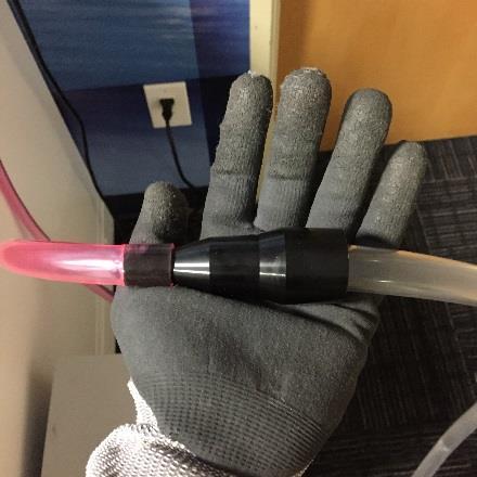
9 or.025 inches in z height, each click is the equivalent of.001 inch) and set this as your zero position (you may need to mark the nosecone to indicate the 0 position later on). o NOTE: Be careful not to cross thread the nosecone to the spindle threads. Doing so will damage the spindle unit. Turn the nosecone clockwise an additional 42 clicks. Use your zero position mark to speed up this process (1 full rotation based on the zero mark is 25 clicks, then an additional 17 clicks). Each tick mark indicates a 0.001in change in height, so this will adjust the tool 0.042in, which is the depth for the Raster Braille cutter. Loosen the Z screw lock nut. This will allow the Z Axis to float. Using the arrow keys on the handy panel to move the nosecone over a flat area of the material. Place a flat plate under the nosecone and insert the Raster Braille cutter until it touches the plate. (bad picture, black glove and shadows blend, can t see the plate you are referring to) 9


 under the nosecone and insert the character cutter until it")
10 Tighten the set screw in the brass knob to lock the cutting tool in position. This will zero the cutter to the proper cut depth for Braille production. Remove the brass cutter knob and Raster Braille cutter from the spindle as one piece using a clock-wise motion. Do not loosen the braille cutter from the brass knob. Rotate the nosecone counter clockwise 9 clicks which will adjust the depth to for the character cutter. Using the same procedure to mechanically calibrate the Raster Braille cutter, remove the brass knob from the character cutter and tighten the brass knob onto the spindle. Again place a flat plate (or spanner wrench) under the nosecone and insert the character cutter until it touches the plate. Tighten the character cutter to the brass knob using the set screw. This will zero the cutter for the proper cut depth for cutting the pictograms and raised text. 10
11 Turn the nose cone counter-clockwise back 33 clicks to the original zero position. Both cutters are now configured for the proper depth and can be easily switched out by tightening/loosening the brass knobs to the spindle assembly. The Raster Braille cutter is set to.042 inch and the character cutter is set to.033 inch. 11


12 INSTALLING ZAD-600 VACUUM ADAPTER Detach the rubber caps at three locations and attach provided cable clips in their place. Install the vacuum ring attachment around nose cone making sure the ring is set level against the nose cone using upwards pressure. Orient ring so that set screw hole is facing forward. 12


13 Using provided 1.5mm Allen key, insert 5mm set screw into hole and tighten until set screw gives resistance. At this point the set screw should be just shy of flush with the vacuum ring attachment surface. o NOTE: Some older ADA kits will use a thumbscrew to secure the ZAD-600 vacuum ring. Arrange the hose and secure it in place with the previously installed cable clips. o NOTE: When you do this, move the spindle head over the entire work area to make sure the hose does not become bent, pulled, or snagged. Connect the duct adapter to the provided US-CHIPSYS-C vacuum. o NOTE: If the duct adapter does not mate flush with the vacuum then take steps such a wrapping the male hose component with PTFE (plumbers) tape or other material to obtain a close fit. 13
14 14

15 INSTALLING AUTO RASTER PEN ATTACHMENT OLD PEN (Shipments before January 2015) Make sure that you have inserted sufficient Raster beads into the pen attachment either through using the included bead funnel or through some other means. 15


16 Using the Z+ key on the Control Panel, raise the Z Axis to its maximum clearance. Ensure that the cutout on the Auto Raster Pen mounting block is on the right Align the index pin on the Raster Pen with the opening located down the center of the spindle unit housing and ensure that the top of the Raster Pen block is flush with the spindle housing. Tighten the set screws using the provided 2mm hexagonal screw driver to attach the Raster Pen attachment to the spindle housing. Tighten the screws in an alternating fashion. 16


17 Make sure that the set screws on the left hand side of the Raster Pen mounting block are flush with the mounting block surface. Otherwise the spindle assembly might not be able to move freely in the z-axis due to tight clearances with the carriage. Use Phillips head screwdriver to remove the 2 screws that hold the cover latch plate to the housing. Remove the lower cable tie that holds the wiring harness to the carriage housing. 17

18 Rotate cable tie mount 180 degrees upwards and install new cable tie. This will allow for extra range of motion in the wiring harness. Install provided acrylic spacer between the latch plate and the motor. Use 3mm Allen key with provided screws to re-attach the latch plate. 18

19 To use the Raster Pen attachment, tighten the Z Axis screw. ss the MENU key multiple times until the OTHERS menu is displayed. Select the OTHER menu and press the ENTER key. Press the MENU key multiple times until the AUTO Z Control Menu is displayed. se the left/right arrow keys to select AUTO Z CONTROL - OFF and press the ENTER key. 19


20 Press the MENU key multiple times to get back to the default screen. Loosen the knob on the Raster pen and lower the knob to the bottom channel lock, then tighten the knob to lock the pen in place. Press the Z- key to lower the Raster Pen to the surface of the ADA sign substrate (the material into which raster beads will be inserted) so the spring compresses about 1/16 1/8 and set this as the Z Origin. 20

21 Remove the spindle housing cover and install plastic spacers at hinge points. This will allow you to close the spindle cover during engraving. 21

22 NEW PEN (Shipments on or after January 2015) Make sure that you have inserted sufficient Raster beads into the pen attachment either through using the included bead funnel or through some other means. Using the Z+ key on the Control Panel, raise the Z Axis to its maximum clearance. Ensure that the cutout on the Auto Raster Pen mounting block is on the right. 22


23 Before attaching the pen to the spindle assembly, check that the set screws on the left hand side of the pen are initially set flush with the interior surface of the mounting block. This will ensure that maximum clearance between the mounting block and the spindle assembly carriage is created allowing for unobstructed motion of the spindle along the z-axis. Tighten the set screws using the provided 2mm hexagonal screw driver to attach the Raster Pen attachment to the spindle housing. Tighten the screws in an alternating fashion. Double check that the set screws on the left hand side of the Raster Pen mounting block are flush with the mounting block surface. 23

24 Use Phillips head screwdriver to remove the 2 screws that hold the cover latch plate to the housing. Remove the lower cable tie that holds the wiring harness to the carriage housing. Rotate cable tie mount 180 degrees upwards and install new cable tie. This will allow for extra range of motion in the wiring harness. 24


25 Install provided aluminum spacer between the latch plate and the motor. Use 3mm Allen key with provided screws to re-attach the latch plate. To use the Raster Pen attachment, tighten the Z Axis screw. 25
26 Press the MENU key multiple times until the I/O, OTHERS, TEACHING, SELF menu is displayed. Select the OTHER menu and press the ENTER key. Press the MENU key multiple times until the AUTO Z Control Menu is displayed. Use the left/right arrow keys to select AUTO Z CONTROL - OFF and press the ENTER key. Press the MENU key multiple times until the REVOLUTION - Control Menu is displayed and press the ENTER key. Press the MENU key multiple times to get back to the default screen. 26
27 Loosen the knob on the Raster pen and lower the knob to the bottom channel lock, then tighten the knob to lock the pen in place. Press the Z- key to lower the Raster Pen to the surface of the ADA sign substrate (the material into which raster beads will be inserted) so the spring compresses about 1/16 1/8 and set this as the Z Origin. Once you are finished calibrating the z-axis for Raster Braille insertion, return the Raster Pen to the neutral position. 27
28 28

29 INSTALLING & SETTING UP ENGRAVELAB EXPERT V9 INSTALLATION Begin a standard installation of EngraveLab Expert V9. Follow directions as prompted by Window s InstallShield Wizard. When you reach the Setup Type screen, choose the Complete EngraveLab Expert Installation. Choose I accept the terms of the license agreement on the next screen. On the Select Features screen, click on the Full Install button and continue as prompted. 29
 in the Manufacturer: field and choose the EGX- 400/600 option in the")
30 When you reach the Cutting Devices screen, select the Yes, I would like to upgrade or install new cutting devices option and click Next. When you reach the Select the cutting devices you wish to update: screen, click on the Roland option (without checking the box) in the Manufacturer: field and choose the EGX- 400/600 option in the Output Device: field. Do not choose the EGX-400/600 Raster Braille options. o NOTE: Checking the Roland box first will prompt the InstallShield Wizard to select all Roland devices. For the purpose of this document we will choose the EGX-600 driver only. 30


31 Choose Continue when asked to install true type fonts on the next screen and continue with installation as prompted. Choose the EngraveLab Installer DVD as the location to install EngraveLab fonts and clipart from. Choose to copy your fonts and clipart to your hard drive for increased performance on the next screen and click OK. As indicated this may take some time. After navigating through a few more screens you will reach the InstallShield Wizard Complete screen. After clicking the Finish button you will now be done with installing EngraveLab Expert V9. 31
32 32


33 CREATING DRIVER COPIES Creating separate drivers for the three different tools you will use (Raster Braille cutter, Auto Raster Pen, character cutter) for the ADA Raster Braille sign making process is a crucial step. This procedure will only have to be performed once for each tool. This procedure will make the ADA workflow simple to learn and simple to teach to new operators of the system. Open EngraveLab V9 and find the Engrave menu in the upper left hand ribbon on the home screen and choose Engraving Defaults from the drop down menu. Click on Setup in the Output dialogue box that pops up. Select the Roland EGX-400 or 600 driver from the Installed Drivers field in the Engraver Setup Window. 33


34 Select the Port tab and double check that the port location for the main driver matches the designated port in the EGX-400/600 driver found under Devices and Printers on your computer. This will ensure that all tool drivers created from this main driver will have the correct port setup. Click Apply once you have selected the correct port. Return to the Engraver tab and make sure that the Roland EGX-600 driver is still selected and click the Create custom copy of selected driver button beneath the Installed Drivers field. 34

35 Character Cutter A new window titled Create custom version of driver will prompt you to name your new driver. Type Character Cutter into the entry field and click OK. Click OK when you arrive back at the Engraver Setup window to return to the Output dialogue window. o In the Options field make sure that Sort and Output Tool Paths are checked. o In the Tool field, select Auto Z Enabled. o Under Smoothing make sure that High is selected. o Under Engrave make sure that Sign Plate and Selected are chosen. 35

36 Once all of the above parameters are set click Apply to confirm your changes. Now click on the Tool Options button at the bottom left hand corner of the Output window. A window with the name Character Cutter will appear. o Under the Tool field, make sure that Auto Z Enabled is again selected. o Set the Cut Velocity to 1.5 o Set the Plunge Velocity to 1 Click OK to return to the Output window. Once you are there click Apply to confirm all of your changes. Braille Drill 36

37 Click on the Setup button to return to the Engraver Setup window. Once again select the Roland EGX-400 or 600 driver and then click the Create custom copy of selected driver button. In the Create Custom Driver pop up window type Braille Drill into the entry field and click OK to return to Engraver Setup. Once you are back in Engraver Setup make sure that your new Braille Drill driver is selected in the Installed Drivers field and click OK to return to the Output window. Once you are in the Output window begin setting up parameters for the Braille Drill (these parameters will differ from those of the Character Cutter, though the process will be similar): o In the Options field make sure that Sort is selected. Do not select Output Tool Paths. o In the Tool field select Braille from the drop down menu. 37
38 o In the Smoothing field make sure that High is selected. o In the Engrave field select Sign Plate and Selected. o Under Object Start Point, select Current. Once all of the above parameters are set click Apply to confirm all of your changes. Now click on the Tool Options button at the bottom left hand corner of the Output window. A dialogue window with the name Braille Cutter will appear. o Under the Tool field, make sure that Braille is selected. o Set the Cut Velocity to 1.5 o Set the Braille Depth to o Set the Plunge Velocity to 1.5 Click OK to return to the Output window. Once you are there click Apply to confirm all of your changes. 38

39 Braille Pen Click on the Setup button to return to the Engraver Setup window. Once again select the Roland EGX-400 or 600 driver and then click the Create custom copy of selected driver button. In the Create Custom Driver pop up window type Braille Pen into the entry field and click OK to return to Engraver Setup. Once you are back in Engraver Setup make sure that your new Braille Drill driver is selected in the Installed Drivers field and click OK to return to the Output window. Once you are in the Output window begin setting up parameters for the Braille Pen (these parameters will differ from those of the Braille Pen, though the process will be similar): 39


40 o In the Options field make sure that Sort is selected. Do not select Output Tool Paths. o In the Tool field select Braille from the drop down menu. o In the Smoothing field make sure that High is selected. o In the Engrave field select Sign Plate and Selected. o Under Object Start Point, select Current. o Under Move, set your x and y offsets for your Auto Raster Braille Pen. These coordinates will be based on the distance between the insertion tip of the Braille pen and the center axis of rotation of the spindle unit as measured from the tip of the nose cone. Standard values for these parameters are the following: X move = -0.3 Y move = o NOTE: Due to differences between manufactured pens and the manual installation process the above measurements will not necessarily work for your setup. It is best to enter these values and then improve upon them through trial and error when actively inserting raster beads into pre-cut holes (this will be covered later). Once all of the above parameters are set click Apply to confirm all of your changes. 40

41 Now click on the Tool Options button at the bottom left hand corner of the Output window. A dialogue window with the name Braille Cutter will appear. o Under the Tool field, make sure that Braille is selected. o Set the Cut Velocity to 1.5 o Set the Braille Depth to o Set the Plunge Velocity to 1.5 Click OK to return to the Output window. Once you are there click Apply to confirm all of your changes and then click the Close button. You are now finished with creating your tool drivers. 41


42 PRODUCING ADA SIGNS Launch EngraveLab Expert V9. You will be prompted with the Plate Size dialogue box where you will be able to setup the desired parameters for your sign. In this case we will use standard settings for an 8in x 8in sign. Click OK to continue. Import the file for the ADA sign that you wish to create. o NOTE: Setup Braille job in accordance with ADA Laws, guidelines and regulations. Please refer to software documentation for generating Braille data. A compliance reference guide also comes with the Accent Signage Raster Braille Kit, (three ring binder) 42


43 Once you have imported your file, EngraveLab will give you a notification in the bottom-left hand corner of the program window that says Seeking Place For Import. You will also notice that your mouse has turned into a bracket. Click and drag this bracket over the black 8in x 8in square and then release to locate your file in the square. Resize and locate the vector image as needed. Once you vector image is correctly placed, click and drag your mouse over the image again to make sure that it is selected (you will know that your vector images are correctly selected when they show as a blue outline). 43


44 Go to Engrave > Create Tool Path and select Male to create all tool paths for your sign. Click OK when the Male dialogue box appears to continue. Go to Engraving Defaults and select the Braille Drill from the Selected Driver dropdown menu. Click Apply and Close to continue. 44


45 Install the Raster Braille cutter into the spindle assembly. Turn on the attached vacuum unit in preparation for cutting. Select the Braille portion of your vector image and create a tool path for it by navigating through Engrave > Create Tool Path > Drill Center. Go to Engrave > Output or use the hot key combo Alt + P to bring up the Cut Toolbox ribbon. Click on the Engrave button on the far right side of the ribbon to output your tool path to the engraver. o NOTE: Close the cover to the spindle assembly before cutting. Otherwise the machine might not let you continue. 45


46 Once the Braille cutter has created holes for the Raster beads, turn off the vacuum unit. Begin configuring the Raster Pen attachment. Adjust the pen to full lowered position. Put the z-axis into locked position. 46
47 Once again visit Engraving Defaults and make sure that the Braille Pen driver has been selected and applied. Navigate to the OTHERS menu on the handy panel and set both REVOLUTION and AUTO Z CONTROL to OFF. Hit Alt + P to bring up the Cut Toolbox ribbon and click the engrave button. The engraver will attempt to insert the Raster Braille beads into the pre-drilled holes using the pen attachment, but it is likely that you will have to adjust the x and y offsets for your Braille Pen driver in the Output window under Engraving Defaults several times before you are successful in doing this. o NOTE: A positive increment in the x move field will adjust the pen s position to the right. Similarly, a positive increment in the y move field will adjusts the pen s position upward. Try correcting for one axis at a time through repeated output cycles. In some instances the pen may jam up with beads while attempting to insert them during the x and y adjustment process. To correct this problem try manually discharging beads through the pen until the any jams are removed. 47

. Put the z-axis into floating position.")
48 Once you have seen the engraver successfully insert beads into the Braille substrate, run your fingers over them to make sure that the fit is secure. If any beads come loose try to adjust the x and y offsets again until the pen inserts beads with a snug fit on the first try. Now configure the engraver for the character cutter (physical tool). Put the z-axis into floating position. Remove the Raster Braille cutter from the spindle assembly and install the character cutter. Return the Braille Pen to the neutral position. 48


49 Navigate to the OTHERS menu in the handy panel and set REVOLUTION and AUTO Z CONTROL to ON. Turn on the vacuum unit that is attached to the ZAD-600 vacuum ring in preparation for cutting. Go into Engraving Defaults and select the Character Cutter driver from the drop down menu in the Output window. Click Apply and Close to continue. Select all vector images that will be cut out with the character cutter and make sure that a tool path is created using the Male option in the Create Tool Path drop down menu. Hit Alt+P to bring up the Cut Toolbox ribbon and hit the Engrave button at the far right to output your latest toolpath. Once the engraver has finished running the toolpath for the character cutter, turn off the vacuum unit. Carefully peel back the top layer of unwanted material on your sign. 49


50 Use a course brush to clean away any excess cuttings not cleared away during the cutting process by the vacuum adapter. Remove the character cutter from the spindle assembly and use the tip of the tool to pry out any remaining pieces of unwanted material (other prying tools can be used for this process). Your sign is now complete! Carefully peal the sign away from AS-10 sheets on the engraving bed and prepare your machine for its next job. 50

51 51
52 52
EGX-400/600 ADA Hardware and Software Setup Guide v1.0
 EGX-400/600 ADA Hardware and Software Setup Guide v1.0 EGX-400/600 ADA Hardware and Software Setup Guide This guide covers configuration of the Raster TM Braille Dot cutter and Character cutter. NOTES:
Diamond Scribing on MDX-40 & JWX-10
 Diamond Scribing on MDX-40 & JWX-0 This document covers diamond scribing using the MDX- 40 and JWX-0 as well as the required accessories. Materials Required: BT-EGX-5, High Precision Spring Loaded Burnishing
Setting up the Roland EGX-300 and EngraveLab to cut IkonicsMetal
 Setting up the Roland EGX-300 and EngraveLab to cut IkonicsMetal Setting Up the Roland EGX-300: 1. Power unit off 2. Remove any existing tools and install the 11/64 solid collet to the bottom of the spindle
Roland PNC-2300A/EGX-300 Bed-Leveling Kit
 Roland PNC-2300A/EGX-300 Bed-Leveling Kit Thank you for purchasing Roland s EGX-300 Bed-leveling Kit. Enclosed is a list of the accessories and the instructions of how to best use the included items. Accessories
G12/G12x USER S MANUAL
 G12/G12x USER S MANUAL TABLE OF CONTENTS SECTION 1 SLIDE CONFIGURATION SECTION 2 SLIDE CONFIGURATION ACCESSORIES SECTION 3 TABLETOP CONFIGURATION SECTION 4 TABLETOP CONFIGURATION ACCESSORIES SECTION 5
Cutter Option Installation Instructions
 This kit includes the parts and documentation necessary to install the cutter option on the Zebra XiII, XiIII, and XiIIIPlus-Series printers. NOTE: The Cutter Option is not available for the 96XiIII. Adding
3D SYSTEMS University CubeX 3D Printer
 3D SYSTEMS University CubeX 3D Printer Lesson Leveling the Print Pad and Print Tips, Setting the Z-Gap Revision date: 10/22/13 1 1 2016 年 6 月 14 日 Objectives After completing this lesson you will: Be able
INSTALLATION INSTRUCTIONS
 INSTALLATION INSTRUCTIONS 19 20 21 01 07 22 23 13 10 12 08 17 18 11 02 14 15 04 03 16 WELCOME PARTS LIST Thank you for purchasing this HealthPoint Technology Cabinet from Humanscale! Before you begin installing
Upgrade Instructions. P/N Revision A. October Printer Terminal Holder * *
 Upgrade Instructions P/N 96-08-0 Revision A October 000 480 Printer Terminal Holder P/N 96-08-0 Revision A *96080* Instructions This terminal holder connects the INTERMEC R 600 Series and 700 Series Computers
EPILOG LASER Table Mountain Parkway Golden, Colorado Phone FAX
 EPILOG LASER 16371 Table Mountain Parkway Golden, Colorado 80403 Phone 303-277-1188 - FAX 303-277-9669 www.epiloglaser.com Procedure Title: Replacing the Optics in your FiberMark Laser Engraver Tools Needed:
TABLE OF CONTENTS SECTION 1 TABLETOP CONFIGURATION SECTION 2 TABLETOP CONFIGURATION ACCESSORIES SECTION 3 SLIDE CONFIGURATION
 S6 USER S MANUAL TABLE OF CONTENTS SECTION 1 TABLETOP CONFIGURATION SECTION 2 TABLETOP CONFIGURATION ACCESSORIES SECTION 3 SLIDE CONFIGURATION SECTION 4 SLIDE CONFIGURATION ACCESSORIES SECTION 5 RACK MOUNT
Unpacking and Installing the Flora 2512 UV Printer. Steps 1: Unscrew the 10mm bolts holding the top. Then remove the top and put in a safe place.
 Unpacking and Installing the Flora 2512 UV Printer Steps 1: Unscrew the 10mm bolts holding the top. Then remove the top and put in a safe place. Step 2: Unscrew 10mm bolts holding the end panels. On the
DIGITAL OBSERVATION GUARD LOW PROFILE PAN TILT KIT USER MANUAL
 DIGITAL OBSERVATION GUARD LOW PROFILE PAN TILT KIT USER MANUAL Version 2.1 June 4, 2013 0 Table of Contents Low Profile Pan Tilt Kit Description... 3 Low Profile Pan Tilt Unit Basic Operation... 4 Mounting
3 Indexer Installation For PRSalpha Tools
 888-680-4466 ShopBotTools.com 3 Indexer Installation For PRSalpha Tools Copyright 2016 ShopBot Tools, Inc. page 1 Copyright 2016 ShopBot Tools, Inc. page 2 Table of Contents General Safety and Precautions...5
Removal and Installation8
 8 Screw Types 8-4 Top Cover Assembly 8-5 Left Hand Cover 8-6 Right Hand Cover 8-10 Front Panel Assembly 8-14 Left Rear Cover 8-15 Right Rear Cover 8-16 Extension Cover (60" Model only) 8-17 Media Lever
Triax A/T QUICK START GUIDE
 Triax A/T QUICK GUIDE Please read all instructions carefully before operating your Triax A/T Key Machine. 1. Preparation A. First remove the Triax A/T machine from its cardboard box and pallet. The machine
Tutorial 1 Engraved Brass Plate R
 Getting Started With Tutorial 1 Engraved Brass Plate R4-090123 Table of Contents What is V-Carving?... 2 What the software allows you to do... 3 What file formats can be used?... 3 Getting Help... 3 Overview
Nov. 07, 2013 p. 5 - changed the B axis unit value to from Changed by Randy per Frank s request.
 Correction notes Nov. 07, 2013 p. 5 - changed the B axis unit value to 45.1389 from 40.0000. Changed by Randy per Frank s request. Jan. 22, 2018 p. 5 - changed the B axis unit value and corresponding picture
Peel/Rewind Upgrade Kit
 Peel/Rewind Upgrade Kit Installation Instructions This kit includes the parts and documentation necessary to install the Peel/Rewind upgrade kit on the following printers: ZM400 ZM600 Read these instructions
BD Laser User Guide * IMPORTANT * PLEASE READ THE FOLLOWING INSTRUCTIONS CAREFULLY AS IMPROPER USE MAY DAMAGE THE MACHINE AND VOID THE WARRANTY.
 BD Laser User Guide * IMPORTANT * PLEASE READ THE FOLLOWING INSTRUCTIONS CAREFULLY AS IMPROPER USE MAY DAMAGE THE MACHINE AND VOID THE WARRANTY. BD Laser arrives ready to use with jaws and cutters preinstalled.
CAMERA ASSEMBLY. Removal/Replacement of the Camera Box Assembly APR-CA. Install Camera Assembly. Remove Camera Assembly
 CAMERA ASSEMBLY Removal/Replacement of the Camera Box Assembly APR-CA REQUIRED TOOLS: 9/64 hex key Small flat-tip screwdriver Remove Camera Assembly camera 1. Locate the camera assembly underneath the
Description: Detailed procedure on removing old bushing and installing new Brake Bushing Replacement Kit 10447
 Procedure: BRAKE BUSHING REPLACEMENT PROCEDURE Product: Document #: Rev: Page: MODEL 7000, 7000A, & 8000 GYRO 078 1 1 of 14 Description: Detailed procedure on removing old bushing and installing new Brake
994 LASER QUICK GUIDE
 994 LASER Quick-Start Guide CONTENTS Machine set-up & password entry Jaw calibration Cut by code & decode How to replace the cutter & change the tracer Short form instructions Replacemente parts list IMPORTANT
think big, print huge
 think big, print huge quick start guide Table of Contents a Receiving and uncrating 5 b bed level & z home 11 c Loading filament 19 d SOFTWARE 23 e Setup 23 f preparing a print 26 g printing on gigabot
When you are ready to build your computer you will have the following materials to work with.
 Copyright 2009 BOSMA Enterprises Chapter 3 Putting the Computer Together When you are ready to build your computer you will have the following materials to work with. 1. One motherboard. 2. One ribbon
Removal and Installation 8
 Removal and Installation 8 8 Introduction 8-2 Service Calibration Guide to Removal and Installation 8-4 Window 8-8 Covers and Trims 8-12 Rear Tray 8-31 Rear Cover 8-32 Media Lever 8-33 Media Lever Position
Ioline CrystalPress. Quick Start Guide
 Ioline CrystalPress Quick Start Guide The Quick Start Guide is intended to help a new user of the Ioline CrystalPress get everything setup and running quickly. Please note that there are important notices,
Installing 6 Indexer: PRS Standard Tools
 888-680-4466 ShopBotTools.com Installing 6 Indexer: PRS Standard Tools Copyright 2016 ShopBot Tools, Inc. page 1 Copyright 2016 ShopBot Tools, Inc. page 2 Table of Contents Overview...5 Installing the
Z Spindle. Revision 1.2. Copyright Newing-Hall, Inc Monroe Street. Toledo, Ohio, NH Part # Last Update July 2003
 Z Spindle Revision 1.2 Copyright 1998-1999 Newing-Hall, Inc. 2019 Monroe Street Toledo, Ohio, 43624 NH Part #2511013 Last Update July 2003 This manual is subject to change without notice. Table Of Contents
Upgrading LVDS Cables Instruction Sheet
 Upgrading LVDS Cables Instruction Sheet INTRODUCTION Use the following instructions to replace the LVDS cables in CP2000-M/MR projectors. The new cables are slightly longer in length and allow for better
Mac Mini Mid 2011 SSD Dual Drive Installation
 Mac Mini Mid 2011 SSD Dual Drive Installation Install a second hard drive in your mid 2011 Mac Mini. Written By: Dozuki System 2017 guides.crucial.com Page 1 of 19 INTRODUCTION Use this guide to install
Mac Mini Mid 2010 SSD Installation
 Mac Mini Mid 2010 SSD Installation Replace your Mac Mini Mid 2010's hard drive for more storage space and an increase in speed. Written By: Dozuki System 2017 guides.crucial.com Page 1 of 15 INTRODUCTION
LANCER / LANCER EVOLUTION (2008 ) REAR VIEW CAMERA MZ380462EX INSTALLATION AND HANDLING INSTRUCTIONS
 REAR VIEW CAMERA MZ380462EX INSTALLATION AND HANDLING INSTRUCTIONS") LANCER / LANCER EVOLUTION (2008 ) REAR VIEW CAMERA MZ380462EX INSTALLATION AND HANDLING INSTRUCTIONS Navigation (MMCS) unit Camera Thank you for purchasing the Mitsubishi Genuine Accessory. To install
LANCER / LANCER EVOLUTION (2008 ) REAR VIEW CAMERA MZ380462EX INSTALLATION AND HANDLING INSTRUCTIONS Navigation (MMCS) unit Camera Thank you for purchasing the Mitsubishi Genuine Accessory. To install
A-dec 570L Dental Light on a DCS System INSTALLATION GUIDE
 A-dec 570L Dental Light on a DCS System INSTALLATION GUIDE C ONTENTS Choose an Installation Guide...... Before You Begin.............. 3 Disconnect the Light Cable........ 3 Cut the Light Cable............
Assembly Instructions for #5630 Medication PalWOW
 Assembly Instructions for #5630 Medication PalWOW Before assembling, please familiarize yourself with all the parts and check to make sure you have all the parts as listed below. A B A & B - The box in
Installation Instructions
 Model: Page: 1 of 6 EEOS130A Sun Machine 450 EL Unit Setup Installation Instructions INSTALLATION MUST BE PERFORMED BY QUALIFIED EQUISERV PERSONNEL ONLY INSTALLATION OVERVIEW: The Installation Instructions
Zebra XiII-Series Printer Quick Reference Guide
 Zebra XiII-Series Printer Quick Reference Guide Contents Media and Ribbon Loading...67 Media Loading...67 Ribbon Loading...70 Operator Controls...72 Front Panel Keys...72 Front Panel Lights...72 Calibration...74
imac Intel 21.5" Retina 4K Display (2017) RAM
 RAM") imac Intel 21.5" Retina 4K Display (2017) RAM Replacement Learn how to replace or upgrade the RAM in your 2017 Retina 4K imac. Written By: Evan Noronha ifixit CC BY-NC-SA www.ifixit.com Page 1 of 38 INTRODUCTION
imac Intel 21.5" Retina 4K Display (2017) RAM Replacement Learn how to replace or upgrade the RAM in your 2017 Retina 4K imac. Written By: Evan Noronha ifixit CC BY-NC-SA www.ifixit.com Page 1 of 38 INTRODUCTION
Q2 XBee Handheld Controller Assembly Guide
 Q2 XBee Handheld Controller Assembly Guide Copyright Quantum Robotics Inc. Q2 Controller V1.0 1 Parts List: The kit comes with 14 individual bags. 1. Case Top and Bottom 2. Case Screw Package containing:
Running a Job on the Large Mill
 Running a Job on the Large Mill Digital Media Tutorial Written by Trevor Williams Turning On the Machine Flip the breaker switch on the front right of the lower part of the controller box to the ON position.
Print Head Replacement and Adjustment Guide for the CD Printer Revision C
 Print Head Replacement and Adjustment Guide for the CD Printer 110488-001 Revision C Rimage is the trademark of the Rimage Corporation. Perfect Image is a registered trademark of the Rimage Corporation.
C764i Integrated LCD Screen Option. Cardio Theater Integrated Bracket Assembly Instructions
 C764i Integrated LCD Screen Option Cardio Theater Integrated Bracket Assembly Instructions Table of Contents 1 2 3 4 5 6 7 Before You Begin... 3 Obtaining Service... 3 Unpacking the Equipment... 3 Important
Written By: senordingdong
 Installation of the UniMac V4 adapter into the Apple imac Intel 17". This enables the usage of non OEM LCD panels, and offers an otherwise unavailable Full HD upgrade. This used for repair of the common
EVOLVE1-M MONITOR ARM
 EVOLVE1-M MONITOR ARM EVOLVE1-M Rev A 2/17 Model EVOLVE1-M-SLV Model EVOLVE1-M-BLK Model EVOLVE1-M-WHT ASSEMBLY AND ADJUSTMENT EVOLVE1-M MONITOR ARM PARTS AND TOOLS PLEASE REVIEW these instructions before
MacBook Pro 15" Core 2 Duo Models A1226 and A1260 SSD Installation
 MacBook Pro 15" Core 2 Duo Models A1226 and A1260 SSD Installation Written By: Dozuki System 2017 guides.crucial.com Page 1 of 10 INTRODUCTION You can install hard drives up to 9.5mm thick. Some drive
Sonnet AV/HPV Card Video Adapter Kit
 Installation Instructions for Power Macintosh 7100 and 8100 Adapter Kit Inventory Before installing the AV/HPV Card Video Adapter, you will require the following items (Figure 1): Included with adapter
Further Information can be found at
 Below is a step by step guide to assembling the Hurricane-Rig. Remember that this is a precision optical instrument. Excessive force can bend critical parts. If treated well it should give many years of
Installation Guide. Retrofit Kit for USB Ready Intraoral Systems
 Installation Guide Retrofit Kit for USB Ready Intraoral Systems Table of Contents Wall-Mount Retrofit Kit... 2 Introduction... 2 Connecting the Articulating and Horizontal Arm Cables... 2 Installing the
Assembly Manual for Mobile X-ray
 Suitable for Kodak 2000, Kodak 2100, Kodak 2200 and Trophy Elytis - 12 th January 2011 William Green Page 1 of 8 Printed 12/01/2011, 2:07:42 PM Mobile X-ray Parts List 1. 6 x M10 x 65mm UNB CAP Bolts 2.
ColorMaxLP Label Roll Rewinder
 ColorMaxLP Label Roll Rewinder 5/2017 INSTALLATION/OPERATOR MANUAL Included: Rewinder Base plate Power supply Power Cord Thumb screws Assembly instructions 1. Install base plate Lift front of printer and
Danalock V3 BT HK EU Mounting guide
 Danalock V3 BT HK EU Mounting guide Page 2 Table of contents Tools needed page 6 Parts involved page 6 Contents of the Danalock box page 7 1. Remove the old cylinder page 8 2. Pull out the old cylinder
Cycles Integrated LCD Screen Option. Cardio Theater Integrated Bracket Assembly Instructions
 Recumbent Upright Cycles Integrated LCD Screen Option Cardio Theater Integrated Bracket Assembly Instructions Table of Contents 1 2 3 4 5 6 7 Before You Begin... 4 Obtaining Service... 4 Unpacking the
Zebra XiIII-Series Printer Safety and Quick Reference Guide
 Zebra XiIII-Series Printer Safety and Quick Reference Guide GB Contents Specifications...75 Electrical...75 Environmental Range...75 Fuses...75 Warnings...76 Installation...76 Use of Shielded Data Cables...76
JLTX Lever and Joystick Replacement Instructions
 JLTX Lever and Joystick Replacement Instructions WARNING THE INCORRECT INSTALLATION OF A LEVER OR JOYSTICK CAN CAUSE AN EQUIPMENT MALFUNCTION FAILURE TO FOLLOW THIS PROCEDURE CAREFULLY COULD RESULT IN
Ioline 300/350HF System
 Quick Start Guide Ioline 300/350HF System User Notice Trademarks Ioline is a trademark of Ioline Corporation. Other product names, logos, designs, titles, words or phrases mentioned within this publication
Ultra short throw lens installation
 Ultra short throw lens installation The ultra short throw lens 0.36 UST GS (P/N: 140-133108-XX) allows you to position your projector as close as possible to your screen or display. Unless otherwise indicated,
Replacement Instructions
 imac G5 Inverter, 20-inch Replacement Instructions Follow the instructions in this document carefully. Failure to follow these instructions could damage your equipment and void its warranty. Note: Online
Eaton LCD Lift Flat Panel Display System. Installation Guide
 Eaton LCD Lift Flat Panel Display System Eaton LCD Lift Flat Panel Display System Installation Guide Copyright 2011 Eaton Corporation, Worcester, MA, USA. All rights reserved. Information in this document
Toshiba Satellite L305-S5946 Power Jack Replacement
 Toshiba Satellite L305-S5946 Power Jack Replacement Replace the power jack in your Toshiba Satellite L305-S5946. Written By: Michael Erberich ifixit CC BY-NC-SA www.ifixit.com Page 1 of 16 INTRODUCTION
Royal RVV-500 (B) Retrofit Kit
 Retrofit Kit") Optipay BV/RC/CC into a Non-Fascia Vending Machine This document contains information for installing and configuring the JCM Optipay DBV-01 Bill Validator, RC-10 Bill Recycler and A-66 Coin Changer into
Optipay BV/RC/CC into a Non-Fascia Vending Machine This document contains information for installing and configuring the JCM Optipay DBV-01 Bill Validator, RC-10 Bill Recycler and A-66 Coin Changer into
CARD PRINTER PRINTHEAD REPLACEMENT INSTRUCTIONS
 CARD PRINTER PRINTHEAD REPLACEMENT INSTRUCTIONS CAUTION: The discharge of electrostatic energy that accumulates on the surface of the human body or other surfaces can damage or destroy the printhead. Please
INSTALLATION INSTRUCTIONS
 2015 F-150 8 MyTouch factory display 360º Vision System (Kit # AVMS-3618) DUE TO THE COMPLEXITY OF THIS KIT PROFESSIONAL INSTALLATION IS REQUIRED CALIBRATION KIT IS REQUIRED FOR FINAL PROGRAMMING -Must
LumaRail Free Stand Bed Assist Rail with IntelliBrite LED Night Light
 LumaRail Free Stand Bed Assist Rail with IntelliBrite LED Night Light Assembly and Operation Instructions Thank you for investing in this premium Platinum Health product. Please carefully follow the assembly
UCIT LIVE HD 4 Camera DVR. Installation Manual. 1/18 Version 1.0
 UCIT LIVE HD 4 Camera DVR Installation Manual 1/18 Version 1.0 This is a step by step guide that will walk you through installing the UCIT LIVE HD 4 Channel Camera System. Basic wiring experience and knowledge
Toucan LT board printer
 Toucan LT board printer Setup and Operating instructions Unpack the Toucan LT board printer as you would any Toucan LT. Follow all cautions associated with installing a standard Toucan LT. Change in wash
SSD Dual Drive Installation
 SSD Dual Drive Installation Replace the optical drive in your imac Intel 21.5". Written By: Dozuki System 2017 guides.crucial.com Page 1 of 18 INTRODUCTION imac won't read disks? Use this guide to replace
Mac Mini Mid 2011 SSD Installation
 Mac Mini Mid 2011 SSD Installation Replace your Mac Mini Mid 2011's hard drive for more storage space and an increase in speed. Written By: Dozuki System 2017 guides.crucial.com Page 1 of 14 INTRODUCTION
Replacing the Galaxy II CRT Monitor with a Flat Screen Monitor Kit # 42638
 Replacing the Galaxy II CRT Monitor with a Flat Screen Monitor Kit # 42638 This kit contains detailed instructions on removing a Galaxy II Daewoo monitor and replacing it with a 19 wide flat screen monitor.
* IMPORTANT * REGISTERING YOUR MACHINE
 * IMPORTANT * REGISTERING YOUR MACHINE Thank you for your purchase of the Keyline 994 Laser. Before continuing with machine setup and use, please complete the following; COMPLETE PRODUCT REGISTRATION FORM
The following forms are included. Computer files are contained in the directory v:\aqg_ops\improve\field_information\mailaudt. 1point.
 TI 201B Forms for Flow Audits by Site Operators The following forms are included. Computer files are contained in the directory v:\aqg_ops\improve\field_information\mailaudt date initials 1point.doc 10/20/95
UCIT LIVE HD 4 Camera DVR. Installation Manual. 10/17 Version 2.0
 UCIT LIVE HD 4 Camera DVR Installation Manual 10/17 Version 2.0 This is a step by step guide that will walk you through installing the UCIT LIVE HD 4 Channel Camera System. Basic wiring experience and
imac Intel 21.5" EMC 2389 SSD Dual Drive
 imac Intel 21.5" EMC 2389 SSD Dual Drive Installation Use this guide to install a second SSD in place of the optical drive. Written By: Dozuki System 2017 guides.crucial.com Page 1 of 17 INTRODUCTION There
TECHKNOW, INC. Kiosk Order Confirmation System INSTALLATION MANUAL. Revision Date: July 11, 2012 Part # Version 3.2
 document Page 1 of 18 TECHKNOW, INC Kiosk Order Confirmation System INSTALLATION MANUAL Revision Date: July 11, 2012 Part # Version 3.2 Techknow, Inc. 393 Mayfield Road Duncan, SC 29334 www.gotechknow.com
FlashCut CNC / Precix Router User s Guide v1.2 Brett Ian Balogh 31.October, Ensure the computer is plugged in. Do not plug the spindle in yet.
 FlashCut CNC / Precix Router User s Guide v1.2 Brett Ian Balogh 31.October, 2011 1. Ensure the computer is plugged in. Do not plug the spindle in yet. 2. Start the computer by pressing the on/off button
Z-Truck (Vertical Moving) Z-truck Flag. Y-Truck (Horizontal Moving) FIGURE 1: VIEW OF THE Z-TRUCK. Flexshaft Assembly
 Z-truck Flag. Y-Truck (Horizontal Moving) FIGURE 1: VIEW OF THE Z-TRUCK. Flexshaft Assembly") Replacing the LCD Cable To remove and replace the LCD Cable you will need the following tools: #2 Phillips screwdriver (magnetic tip preferred) Socket wrench with 10mm socket Removing the Side Panel 1.
Replacing the LCD Cable To remove and replace the LCD Cable you will need the following tools: #2 Phillips screwdriver (magnetic tip preferred) Socket wrench with 10mm socket Removing the Side Panel 1.
Removing and Replacing Parts
 Removing and Replacing Parts Preparing to Work Inside the Computer Recommended Tools Screw Identification System Components Hard Drive Fixed Optical Drive Media Bay Devices Memory Modules Mini PCI Card
Peel & Present Option Rev.C
 Peel & Present Option 92-2479-01 Rev.C Contents of the Peel & Present Kit This kit contains the following items: Peel and Present Mechanism Assist Roller Bushing Follow the steps below to install these
HP Pavilion dv7-6c90us Cooling fan Replacement
 HP Pavilion dv7-6c90us Cooling fan Replacement This guide will walk you through the process of replacing the cooling fan in an HP Pavilion dv7 laptop. Written By: Angelina Clayton ifixit CC BY-NC-SA www.ifixit.com
Treadmill Integrated LCD Screen Option. Cardio Theater Integrated Bracket Assembly Instructions
 Treadmill Integrated LCD Screen Option Cardio Theater Integrated Bracket Assembly Instructions Table of Contents 1 2 3 4 5 6 Before You Begin... 4 Obtaining Service... 4 Unpacking the Equipment... 4 Important
Encore XT Manual Gun Upgrade Kit
 Instruction Sheet P/N 1600823-01 Encore XT Manual Gun Upgrade Kit 1600834 Introduction Follow these instructions to upgrade your Encore manual spray gun to the improved design of the Encore XT spray gun.
APES-14 HD-6500 & HD-7000 Version Operator s Training Manual
 APES-14 HD-6500 & HD-7000 Version Operator s Training Manual Issue A1 09/03 PDI Part # 900600 Performance Design Inc. 2350 East Braniff St. Boise Idaho 83716 This manual contains very important safety
SKYLEVEL INSTALLATION Manual
 SKLEVEL INSTALLATION Manual Southwest Windpower, Inc. 80 West Route 66 Flagstaff, Arizona 8600 USA Phone: 928-779-9463 Fax: 928-779-485 www.skystreamenergy.com June 2009 Southwest Windpower, Inc. All Rights
Contents. Communications, Modular (excludes 17B, 17C, MK 21 and KMB BandMasks ) 1.1 Daily Maintenance. 1.2 Monthly Maintenance (or
 1.1 Daily Maintenance. 1.2 Monthly Maintenance (or") Communications, Modular (excludes 17B, 17C, MK 21 and KMB BandMasks ) Daily Maintenance Communications, Modular (excludes 17B, 17C, MK 21 and KMB BandMasks ) Contents COM-1 COM-1 1.1 Daily Maintenance
Communications, Modular (excludes 17B, 17C, MK 21 and KMB BandMasks ) Daily Maintenance Communications, Modular (excludes 17B, 17C, MK 21 and KMB BandMasks ) Contents COM-1 COM-1 1.1 Daily Maintenance
OnePlus 5 Screen and Digitizer Assembly Replacement
 OnePlus 5 Screen and Digitizer Assembly Replacement Follow this guide to replace the screen and digitizer for the OnePlus 5. This replaces the screen as well as the frame it is attached to. Written By:
2M IR Mini Dome Quick Installation Guide
 1 2M IR Mini Dome Quick Installation Guide Please follow the installation steps below to set up 2M IR Mini Dome IP Camera. Check the package contents against the list below. See P.1 Physical overview.
PDC / ECIS. Display Update update with conversion kit Display Update. Contents. General information. Important notes.
 US Toll Free: 800.BODE.TEC BodeTechnicalServices.com Display Update PDC / ECIS Display Update update with conversion kit 535268 Contents General information Important notes Requirements Conversion instructions
The Nureva Span ideation system. Installation guide. Single panoramic system
 The Nureva Span ideation system Installation guide Single panoramic system Important SAFETY WARNINGS Prior to the installation of this product, the installation instructions should be completely read and
Power Supply, 17-inch
 apple imac G5 Power Supply, 17-inch Replacement Instructions Follow the instructions in this sheet carefully. Failure to follow these instructions could damage your equipment and void its warranty. Note:
Written By: Walter Galan
 imac Intel 17" Power Supply Replacement Written By: Walter Galan ifixit CC BY-NC-SA www.ifixit.com Page 1 of 18 INTRODUCTION Power hungry? Keep those electrons flowing by replacing your power supply. TOOLS:
Dremel Idea Builder 3D40. Various infill options are available from Simplify 3D software. Varies dependent on the infill and size of your object.
 Guide for Dremel Printing General information The Dremel Idea Builder 3D printer extrudes PLA plastic along a tool path to create layers much like our higher end Dimension. The Dremel however does not
CHAPTER 5 UNIT MAINTENANCE INSTRUCTIONS
 FPU SYSTEMS OPERATION MANUAL (INCLUDING REPAIR PARTS & SPECIAL TOOL LIST) STANDARD AND SPECIALIZED FPU MODULES BOH FPU Field Pack-up Units CHAPTER 5 UNIT MAINTENANCE INSTRUCTIONS BOH-PM-0-5 06 BOH Environmental
MacBook Pro 15" Core 2 Duo Models A1226 and A1260 SSD Dual Drive Installation
 MacBook Pro 15" Core 2 Duo Models A1226 and A1260 SSD Dual Drive Installation Use this guide to install a second hard drive in place of the optical drive. Written By: Dozuki System 2017 guides.crucial.com
Dell Inspiron XPS and Inspiron 9100 Service Manual
 Dell Inspiron XPS and Inspiron 9100 Service Manual Dell Inspiron XPS and Inspiron 9100 Service Manual Before You Begin Memory Module, Mini PCI Card, and Devices System Components Subwoofer Bluetooth Card
641G-001A PRINTER KIT INSTRUCTIONS
 641G-001A PRINTER KIT INSTRUCTIONS P-11351 5/05/98 SAFETY The installer of this equipment must assume the responsibility for his own safety, and that of those working around him. He must also make sure
xr Fiber Platform User Guide
 FOR USE WITH THE XR FIBER APPLICATION xr Fiber Platform User Guide The most current version of this User Guide can be found at: www.xrapid-environment.com/resources/ Important: This Guide describes how
HQ Pro-Stitcher Hardware Upgrade Installation Instructions 01/15/13
 Getting Started Monitor Styles HQ Pro-Stitcher Hardware Upgrade Installation Instructions 01/15/13 1. Identify the monitor style on your HQ Pro-Stitcher by comparing to the photos at the right. 2. Find
To connect the AC adapter:
 Replacing the AC Adapter Replacing the AC Adapter 3 Plug the power cord into a wall outlet. The power indicator turns on. To connect the AC adapter: Connect the power cord to the AC adapter. Power indicator
QUICK START GUIDE. Android or Windows Tablet. 1 Tower PC. Mount the RazorGage to your Own Table. Assembling the RazorGage ST with RazorGage Table
 QUICK START GUIDE Android or Windows Tablet If you have a Tablet Style Interface (PC or Android) then skip this step. 1 Mount monitor and attach legs to control tower using hardware provided and place
ENJOY Introduction. Software Installation* Hardware. Calibration Settings. Print test. Appendex. Install print S/W Driver Install
 Quick Start Manual 1 ENJOY Introduction C O N T E N T S 6 5 Appendex 4 Print test 3 2 Hardware Calibration Settings Software Installation* Install print S/W Driver Install Hardware Intro Cable installation
DIGITAL Server Rackmount Installation Guide
 DIGITAL Server Rackmount Installation Guide Part Number: ER-PCSRA-IA. E01 Digital Equipment Corporation December 1997 The information in this document is subject to change without notice and should not